

Page 1

SPECIFICATIONS
Model Number: ADHB
Electrical Rating: 9 volt alkaline battery
U.L. temperature rating: 135°F (58°C) fixed temperature
U.L. Maximum ambient
temperature at unit: 100°F
Operating temperature: -10°F to 158°F (-23°C to 70°C)
U.L. Recommended coverage: 2500 square feet (see Note A)
U.L. Recommended spacing: 50 feet
Maximum distance from wall: 25 feet (see Note B)
HEAT ALARM FEATURES
•
This heat alarm is powered by a 9-volt alkaline battery.
•
Optional tamper-resist feature.
•
Unique “battery missing” lockout – heat alarm will not attach to
the mounting bracket if a battery is not in the battery pocket.
•
Improperly connected or weak battery signal – heat alarm will
sound a short beep once a minute if the battery is weak or
improperly connected.
•
Red LED indicates that the heat alarm is receiving power from the
battery and is working under normal operation, or in alarm.
•
Loud alarm horn—85 decibels at 10 feet—sounds to alert you
to an emergency.
•
Test button checks heat alarm operation.
IMPORTANT SAFETY INFORMATION
PLEASE READ AND SAVE
THESE INSTRUCTIONS
WARNING
•
This heat alarm requires a working 9-volt battery to operate
properly. This heat alarm WILL NOT work if the battery is
removed, drained or improperly connected. DO NOT use any
other kind of battery except as specified in this manual.
•
The Push-to-Test button accurately tests all heat alarm
functions. For temperatures that are below -10°F use a hand
held hair dryer and blow hot air into heat alarm to test. DO
NOT use any other test method. Test heat alarm weekly to
ensure proper operation.
•
This heat alarm should be installed only by a licensed,
qualified electrician. Observe and follow all local and national
electrical and building codes for installation.
!
1
Heat Alarm
with 9V
Alkaline
Battery
110-1146B
135°F (58°C) FIXED TEMPERATURE
MODEL ADHB
PLEASE READ AND SAVE
THIS MANUAL
Installer: Please leave this
manual with the product.
WARNING! Heat alarms are not life safety devices and are not designed to
detect smoke or fire. Heat alarms detect temperatures of 135°F or greater,
and are intended to be used as supplements to smoke alarms by providing early warning. See the IMPORTANT SAFETY INFORMATION section of
this manual.
NOTE A: Maximum alarm coverage has been determined by UL to provide detection
time equal to sprinkler devices spaced at 10-ft intervals (100 square foot area) on a
smooth ceiling 15 ft 9 in. high. Higher ceilings can adversely affect detection time. In
some instances, earlier detection may be obtained by reducing the distance between
detectors. See the latest edition of the NFPA 72E, Automatic Fire Detectors.
NOTE B: Maximum distance is measured from any wall partition or ceiling projection
extending down more than 12 inches.
110-1146B.qxd 12/12/06 3:16 PM Page 1
Page 2

•
This heat alarm is designed to be used inside a single family
building only. In multi-family buildings, each individual living
unit should have its own heat alarm. Do not install in nonresidential buildings or places which house many people like hotels,
motels, dormitories, hospitals, nursing homes, or group homes.
This heat alarm is not a substitute for a complete alarm system.
•
Heat alarms should be used in conjunction with smoke alarms
in order to provide early warning of heat, smoke or fire. In addi-
tion, smoke alarms should be installed in every bedroom and on
every level of the home.
•
Heat alarms may not alert every household member every
time. There may be limiting circumstances where a household
member may not hear the alarm (e.g., outdoor or indoor noise,
sound sleepers, drug or alcohol usage, the hard of hearing,
etc.). If you suspect that this smoke alarm may not alert a
household member, install and maintain specialty smoke
alarms. Current studies have shown smoke alarms may not
awaken all sleeping individuals, and that it is the responsibility
of individuals in the household that are capable of assisting
others to provide assistance to those who may not be awakened by the alarm sound, or to those who may be incapable of
safely evacuating the area unassisted.
•
This heat alarm can only sound its alarm when it detects
temperatures of 135°F or greater. Heat alarms do not detect
smoke, flame, or gas. In some fires, hazardous levels of toxic
chemicals and smoke can build up before a heat alarm will operate. Temperatures may not reach 135°F to activate the heat
alarm QUICKLY ENOUGH to ensure safe escape.
•
Heat alarms should be used to supplement smoke alarms.
This alarm may not always detect slow, smoldering, low heat producing fires, and fires that are in a different room than the heat
alarm. In addition, heat from a nearby fire may bypass the heat
alarm.
•
Heat alarms have limitations. This heat alarm is not foolproof
and is not warranted to protect lives or property from fire. Heat
alarms are not a substitute for insurance. Homeowners and renters
should insure their life and property. In addition, it is possible for
the heat alarm to fail at any time.
HEAT ALARM PLACEMENT
Heat alarms give an audible warning when the temperature at the
alarm reaches 135°F. Heat alarms are ideal for kitchens, garages,
basements, boilers rooms, attics, and other areas where there are
normally high levels of fumes, smoke, or dust which are also areas
where smoke alarms should not be installed due to risk of false
nuisance alarms.
The National Fire
Protection Association’s
(NFPA) minimum requirement, as stated in
Standard 72, Chapter 2,
reads as follows:
“2-2.1.1.1 Smoke detectors shall be installed outside of each separate
sleeping area in the immediate vicinity of the bedrooms and on each
additional story of the family living unit including
basements and excluding
crawl spaces and unfinished attics. In new construction a heat detector
also shall be installed in
each sleeping room.”
2
BEDROOM BEDROOM
FINISHED ATTIC
UNFINISHED ATTIC
BASEMENT
UTILITY
ROOM
LIVING
ROOM
KITCHEN
GARAGE
HALL
SINGLE STORY RESIDENCE/ APARTMENT/ MOBILE HOME
BEDROOMKITCHENDINING ROOM
LIVING ROOM
GARAGE
BEDROOM
BEDROOM
EXISTING
HOMES
TWO STORY RESIDENCE
110-1146B.qxd 12/12/06 3:16 PM Page 2
Page 3
In addition, the California State Fire Marshal states: “Early
warning fire detection is best achieved by the installation of fire
detection equipment in all rooms and areas of the household
as follows: A heat detector installed in each separate sleeping
area (in the vicinity, but outside the bedrooms) and heat or
smoke alarms in the living rooms, dining rooms, bedrooms,
kitchens, hallways, attics, furnace rooms, closets, utility and
storage rooms, basements and attached garages.”
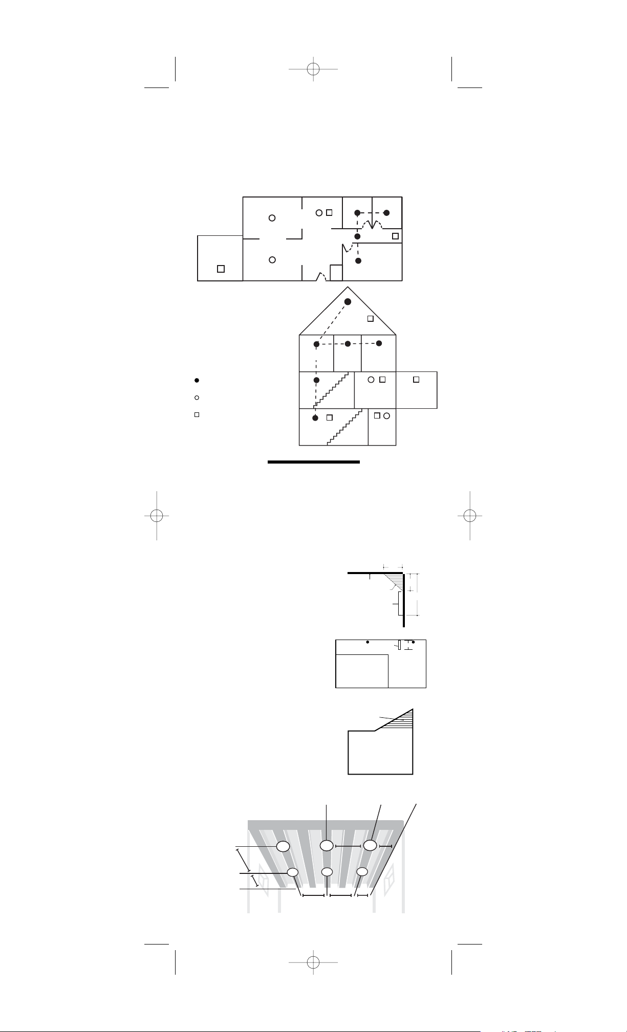
HEAT ALARM LOCATIONS
•
Install a heat alarm as close to the center of the ceiling as
possible. If this is not practical, mount no closer than 4 inches
from a wall or corner.
•
If ceiling mounting is not practical or the mounting surface
becomes considerably warmer or cooler than the room (such
as a poorly insulated ceiling, below an unfinished attic or an
exterior wall) and if local codes allow, install heat alarms on
walls, between 4 and 12 inches from ceiling/wall intersections.
•
Install heat alarms on peaked, cathedral,
or gabled ceilings 3 feet from the highest
point (measured horizontally).
•
In a room with open joists or beams, all
ceiling mounted heat alarms shall be
located on the bottom of joists or
beams – not in joist channels.
•
Heat alarms installed on an openjoisted ceiling shall have their
smooth ceiling spacing reduced to
no more than half of the listed
spacing when measured at right
angles to solid joist.
3
KEY:
NFPA minimum REQUIRED smoke
alarm locations
NFPA RECOMMENDED additional
smoke alarm locations
Recommended heat alarm locations
NEW
CONSTRUCTION
HOMES
BEDROOM BEDROOM
FINISHED
ATTIC
UNFINISHED
ATTIC
BASEMENT
UTILITY
ROOM
LIVING
ROOM
KITCHEN
GARAGE
HALL
SINGLE STORY RESIDENCE/ APARTMENT/ MOBILE HOME
BEDROOMKITCHENDINING ROOM
LIVING ROOM
BEDROOM
BEDROOM
TWO STORY RESIDENCE
GARAGE
110-1146B.qxd 12/12/06 3:16 PM Page 3
CEILING
ACCEPTABLE HERE
STUB WALL
ACCEPTABLE IN
THIS AREA
NEVER HERE
TOP OF DETECTOR
ACCEPTABLE HERE
SOFFIT
PEAKED CEILING
4 IN
(0.1m )
4 IN
(0.1m )
MINIMUM
12 IN
(0.3 m )
MAXIMUM
SIDE
WALL
24"
1/2 ft.
121/2 ft.
(3.8 m)
50 ft. (15 m)
25 ft. (7.6 m)
25 ft.
(7.6 m)
25 ft.
(7.6 m)
25 ft.
(7.6 m)
12
(3.8 m)
Page 4

HOW TO INSTALL
THIS HEAT ALARM
WARNING: This heat alarm is shipped with the bat-
tery disconnected. You MUST properly
connect the battery before mounting the
heat alarm to the wall or ceiling. The
heat alarm will not operate without the
battery first being properly connected.
WARNING: This heat alarm should be installed only
by a qualified electrician. Heat alarm
wiring to be used shall be in accordance
with the provisions of Article 210 and
760 of the National Electrical Code,
ANSI/NFPA 70, and any local codes that
may apply. Interconnect wire location
shall be in accordance with NEC Article
300.3b.
THIS HEAT ALARM SHOULD BE INSTALLED IN ACCORDANCE
WITH THE NATIONAL FIRE PROTECTION ASSOCIATION’S
STANDARD 72 (National Fire Protection Association,
Batterymarch Park, Quincy, MA 02269).
1. From back of heat alarm, remove mounting plate. (To deter a
person from tampering with or removing the unit from the trim
ring once installed, you may wish to later engage tamperresist feature. To do this, twist out and set aside one of the
pins molded into plate. Both pins are exactly the same.)
2. Place mounting bracket against ceiling or wall where you
wish to mount the smoke alarm. Use a pencil to trace the
inside of the two mounting hole locations.
3. Drill two holes, using a 3/16 in. (5 mm) drill bit in the centers
of the hole locations and insert anchors into holes.
4. Use mounting screws to secure mounting bracket to ceiling
or wall.
5. Lift open battery pocket door.
6. Connect new 9-volt battery to
battery connector inside battery
pocket. BE SURE BATTERY IS
SECURELY CONNECTED. Heat
alarm may beep briefly when
battery is installed.
7. Close battery pocket door,
snapping it into place. (For tamper-resist, use long-nosed pliers
to remove thin plastic from
notch on heat alarm edge.)
8. Position heat alarm to
mounting plate and turn
clockwise to lock into
place. To engage tamperresist feature, insert pin into
notch on edge of heat alarm after alarm is properly positioned
in base. See instruction #7 on the previous page. NOTE: The
tamper-resist pin must be removed to change the batteries
and replaced when done.
NOTE: Heat alarm will not mount to plate if battery is not installed.
9. Test heat alarm. See TESTING THE HEAT ALARM.
WARNING:
DO NOT connect this heat alarm to any
other detector or electrical device. Doing
so will cause the heat alarm to operate
improperly or fail to operate.
DO NOT install heat alarms:
•
In areas with high humidity, like bathrooms or areas near dishwashers or washing machines. Install at least 10 feet (3 meters)
away from these areas, if possible.
•
Near air returns, heating and cooling supply vents, fans, decorative objects, window molding etc. that may prevent heat from
entering the unit thus interrupting its alarm.
•
In rooms where temperatures may fall below -10°F (23°C) or
rise above 100°F (38°C).
•
Near fluorescent lights - electrical noise and flickering may
affect the alarm’s operations.
!
4
Remove thin plastic
from notch
Mobile home installation
For mobile homes built after 1978, install heat alarms as directed
above. For mobile homes built before 1978, install heat alarms on
an inside wall between 4 and 12 inches from the ceiling. (Older
mobile homes have little or no insulation in the ceiling which may
affect the heat alarm’s ability to detect heat properly.) This is
especially important if the ceiling is unusually hot or cold.
Insert pin here
!
!
110-1146B.qxd 12/12/06 3:16 PM Page 4
Page 5

RED LED INDICATOR
This heat alarm features a red LED indicator. The LED indicates
the following:
Blinks once a minute — indicates presence of a working battery.
Blinks once a second — heat alarm senses heat and simultane-
ously sounds an audible alarm.
OFF — DC power is not present.
TESTING THE HEAT ALARM
WARNING
•
Test each heat alarm and smoke alarm in your home to be sure
it is installed correctly and operating properly.
•
Stand at arm’s length from the heat alarm when testing. The
alarm horn is loud to alert you to an emergency and can be
harmful to hearing.
•
Test heat alarms weekly and upon returning from vacation or
when no one has been in the household for several days.
Test all heat alarms weekly by doing the following:
1. Observe the red LED. If it blinks once per minute, it indicates
the heat alarm is receiving power from the battery.
2. Firmly depress the Push-to-Test button for at least five (5) sec-
onds. The heat alarm will sound a loud beep about 4 times a
second. The alarm may sound for up to 10 seconds after
releasing the Push-to-Test button.
3. If heat alarm does not sound check to make sure the battery is
properly installed. Retest heat alarm.
DANGER: If alarm horn sounds, and heat alarm is not
being tested, the heat alarm is sensing 135°
F or greater temperature. THE SOUND OF
THE ALARM HORN REQUIRES YOUR IMMEDIATE ATTENTION AND ACTION.
MAINTENANCE AND CLEANING
In addition to weekly testing, this heat alarm requires yearly battery
replacement and periodic cleaning to remove dust, dirt, and debris.
BATTERY REPLACEMENT
Replace battery at least once a year or immediately when the low
battery signal sounds once a minute. Batteries should be
replaced regularly.
Use only the following batteries as replacements in this heat alarm:
Energizer 522 or 1222, or Duracell MN 1604.
WARNING: DO NOT USE ANY OTHER TYPE OF
BATTERY, EXCEPT AS SPECIFIED IN
THIS MANUAL. DO NOT USE RECHARGEABLE BATTERIES.
1. Turn heat alarm counterclockwise to detach from mounting plate.
2. Gently pull down heat alarm.
3. From back of heat alarm, lift tab to open battery pocket door.
4. Remove battery from pocket. Disconnect and discard drained
battery from battery connector.
5. Connect a fresh, 9-volt battery to connector. The battery will
fit only one way. Be sure battery connector is securely
attached to battery terminals.
6. Place battery into battery pocket.
7. Close battery pocket door. Push down until it snaps into
place.
8. Reattach heat alarm to mounting plate by turning heat alarm
clockwise until it snaps into plate.
9. Test heat alarm using Push-to-Test button.
CLEANING
Clean the heat alarm at least once a month to remove dust,
dirt, or debris.
•
Using the soft brush or wand attachment to a vacuum cleaner,
vacuum all sides and cover of heat alarm. Be sure all the vents
are free of debris.
•
If necessary, use a damp cloth to clean heat alarm cover.
IMPORTANT: Do not attempt to remove the cover or clean inside
the heat alarm. THIS WILL VOID YOUR WARRANTY.
5
!
!
!
110-1146B.qxd 12/12/06 3:16 PM Page 5
Page 6

REPAIR
CAUTION: Do not attempt to repair this heat alarm.
Doing so will void your warranty.
If heat alarm is not operating properly, see TROUBLESHOOTING.
If necessary, and if still under warranty, return heat alarm to
Invensys Controls Americas. Pack it in a well-padded carton, shipping prepaid with a note describing the nature of the problem and
proof of purchase date, to:
Invensys Controls Americas
Product Service Department
28C Leigh Fisher Blvd.
El Paso, TX 79906
If the heat alarm is no longer under warranty, replace the heat
alarm immediately with a comparable Firex brand heat alarm.
PRACTICE FIRE SAFETY
If the heat alarm sounds its alarm horn, and you have not pushed
the test button, it is warning of a dangerous situation.
Your immediate response is necessary. To prepare for such
occurrences, develop family escape plans, discuss them with
ALL household members, and practice them regularly.
•
Expose everyone to the sound of the smoke alarm and heat
alarm and explain what the sounds means.
•
Determine TWO exits from each room and an escape route to
the outside from each exit.
•
Teach all household members to touch the door and use an
alternate exit if the door is hot. INSTRUCT THEM NOT TO
OPEN THE DOOR IF THE DOOR IS HOT.
•
Teach household members to crawl along the floor to stay
below dangerous smoke, fumes, and gases.
•
Determine a safe meeting place for all members outside the
building.
WHAT TO DO IN CASE OF A FIRE
1. Don’t panic; stay calm.
2. Leave the building as quickly as possible. Touch doors to
feel if they are hot before opening them. Use an alternate
exit if necessary. Crawl along the floor, and DO NOT stop
to collect anything.
3. Meet at a prearranged meeting place outside the building.
4. Call the fire department from OUTSIDE the building.
5. DO NOT GO BACK INSIDE A BURNING BUILDING. Wait for
the fire department to arrive.
These guidelines will assist you in the event of a fire. However, to
reduce the chance that fires will start, practice fire safety rules
and prevent hazardous situations.
!
6
110-1146B.qxd 12/12/06 3:16 PM Page 6
Page 7

TROUBLESHOOTING
WARNING: DO NOT disconnect battery to quiet
an unwanted alarm. This will remove
your protection. Fan the air or open
a window to remove heat or dust.
PROBLEM SOLUTION
Heat alarm does not
1. Check that battery is
sound when tested. properly attached to
connector.
2. Clean heat alarm.
Heat alarm beeps about Replace battery. See
once a minute. Battery Replacement
in the MAINTENANCE
AND CLEANING section.
Heat alarm sounds 1. Clean heat alarm.
unwanted alarms. See Cleaning in the
MAINTENANCE AND
CLEANING section.
2. Hire an electrician to
move heat alarm to
a new location. See
HEAT ALARM
PLACEMENT.
NOTE: Push test button for
at least five (5) seconds
while testing!
!
7
WARRANTY INFORMATION
Invensys Controls Americas warrants to the original consumer purchaser each new
heat alarm, excluding battery, to be free from defects in material and workmanship under
normal use and service for a period of five (5) years from the date of purchase. Invensys
Controls Americas agrees to repair or replace, at its option, any defective heat alarm pro-
vided that it is returned with postage prepaid and with proof of purchase date to Invensys
Controls Americas. This warranty does not cover damage resulting from accident, mis-
use or abuse, or lack of reasonable care of the product. This warranty is in lieu of all other
express warranties, obligations or liabilities. THE IMPLIED WARRANTIES OF MER-
CHANTABILITY AND FITNESS FOR A PARTICULAR PURPOSE ARE LIMITED TO A PERIOD
OF FIVE (5) YEARS FROM PURCHASE DATE. Some states do not allow limitations on how
long an implied warranty lasts, so the above limitations may not apply to you. IN NO CASE
SHALL INVENSYS CONTROLS AMERICAS BE LIABLE FOR ANY INCIDENTAL OR CONSE-
QUENTIAL DAMAGES FOR BREACH OF THIS OR ANY OTHER WARRANTY, EXPRESS OR
IMPLIED, WHATSOEVER, EVEN IF THE LOSS OR DAMAGE IS CAUSED BY ITS NEGLI-
GENCE OR FAULT. Some states do not allow the exclusion or limitation of incidental or con-
sequential damages, so the above limitation or exclusion may not apply to you. This
warranty gives you specific legal rights, and you may also have other legal rights which
vary from state to state.
110-1146B.qxd 12/12/06 3:16 PM Page 7
Page 8

8
NOTES
191 E. North Avenue
Carol Stream, Illinois 60188 USA
www.invensyscontrols.com
©2006 Invensys Controls 110-1146B
110-1146B.qxd 12/12/06 3:16 PM Page 8
 Loading...