

Page 1
®
Clipsal Lifesaver
Heat Alarm
Installation / Operating Instructions and Warranty
755H Heat Alarm
240V~, 50Hz, heat alarm with 9V d.c. battery backup
Suitable for interconnection with up to 39 smoke and
heat alarms.
WARNING. Heat alarms alone are not suffi cient for
life safety as they are not designed to detect smoke.
They are intended to detect a temperature of 73°C
to comply within the range of 58°C to 88°C per AS
1603.3-1996,to provide additional source of information
that is supplementary to that provided by
smoke alarms to increase the probability
that an early warning will be provided
and so enhance life safety and property
protection. See “Heat Alarms Have
Limitations” in the IMPORTANT SAFETY
INFORMATION section of this manual.
IMPORTANT: Please leave this manual with the owner.
110-656C
HEAT ALARM DESCRIPTION:
Model 755H Heat Alarm, 240V~, 50Hz, with 9V d.c.
battery backup.
Thank you for purchasing a quality Clipsal Lifesaver
®
755H Heat Alarm. The 755H Heat Alarm is a mains
powered device, with a battery backup that will operate
in the event of mains power failure. The alarm will sound
when it detects a temperature of 73° to comply within the
range of 58°C to 88°C per AS1603.3-1996. Please read the
following instructions carefully to ensure correct installation
and maintenance.
These units are not designed to detect fl ame. A 5-year
warranty (excluding batteries) is included. A licensed
electrician or similarly qualifi ed person to SAA Wiring Rules
(AS3000) and relevant Building Codes must carry out
installation of the Clipsal Lifesaver® 755H Heat Alarm.
HEAT ALARMS HAVE LIMITATIONS
The Clipsal Lifesaver® Series Heat Alarm is not foolproof
and is not warranted to protect lives or property from fi re.
Heat alarms are not a substitute for insurance. In addition,
it is possible for the heat alarm to fail at any time. For this
reason you must test the heat alarm weekly and replaced
every ten years.
HEAT ALARM FEATURES
•
The heat alarm is powered from a 240V~ supply, and
has a 9V d.c. battery back-up source. Mains powered
heat alarms with battery back up offer added protection
in the event of a power failure or a fl at battery.
•
This model 755H Heat Alarm may be interconnected
with as many as 39 other heat alarms of the same
model, or 39 off any of the Clipsal Lifesaver®, 755
series, 240V~ smoke alarms, connected to the
same phase.
•
Optional tamper resistant feature serves as a safeguard
against tampering.
•
Unique “battery missing” device. The heat alarm will not
attach to the mounting bracket if a battery is not in the
battery compartment.
•
The heat alarm will sound a short beep about once a
minute if the battery is low or improperly connected.
•
Multi-purpose green and red LEDs indicate that the
heat alarm is connected to the a.c. supply, is working
normally, or is in alarm.
•
Loud alarm sounder, 85 decibels [dB(A)] at 3 metres,
will sound to alert you in an emergency.
•
Test button checks heat alarm operation.
2
SPECIFICATIONS
Model Number 755H
Electrical Rating 240V~, 9V d.c. battery
back up
Interconnecting Up to 39 other Clipsal
Lifesaver® series Smoke or
Heat Alarms.
Temperature Rating The alarm point of this heat
alarm is 73°C to comply
within the range of 58° to
88°C per AS1603.3-1996
Recommended Coverage 50m
2
Recommended Spacing 5.3m
Maximum Distance from Wall 7.7m
Maximum Ceiling Height 6.0m
Compatible Isolation Unit Catalogue No. 756
IMPORTANT SAFETY INFORMATION
Please read and save these instructions
•
This heat alarm requires constant 240V~ power and a
healthy 9V d.c. battery to operate properly. This heat
alarm will not work if a.c. supply is not connected, or
has failed or been interrupted for any reason, and the
batteries have been removed or are fl at or improperly
connected. Do not use any other kind of battery except
as specifi ed in this manual. Do not interconnect this
heat alarm to any other type of smoke alarm or
heat alarm or auxiliary device, except those listed in
this manual.
•
The Push-to-Test button accurately tests all heat
alarm functions. Do not use any other test method for
routine testing. Test heat alarm weekly to ensure
proper operation.
•
Higher ceilings will increase the time needed by the
heat alarm to detect a fi re. In most dwellings the
ceiling height will keep this reaction time within
acceptable limits. However, ceilings with a height of
over 6 metres may delay the reaction time of the heat
alarm signifi cantly.
•
Advice from your local distributor or Fire Brigade should
be obtained when installing a heat alarm on a ceiling
higher than 6m.
•
Only a qualifi ed electrician or similarly qualifi ed
person should install this heat alarm. The installation
should comply with all prevailing local, regional and
national codes.
•
This heat alarm is designed to be used only as part of
the protection of a single-family dwelling or a house in
multiple occupation of no more than two storeys. It may
also be used in conjunction with smoke alarms within
individual fl ats or apartments in larger houses in
3
multiple occupation, to provide an early warning to
occupants of a fi re in a room within the dwelling but a
communal fi re alarm system should also be provided
in such cases.
•
Heat alarms should only be used in conjunction with
smoke alarms, with which the heat alarms should be
interconnected, in order to provide early warning of
heat, smoke, or fi re. Smoke alarms should be installed
on every level of the dwelling.
•
Interconnected heat alarms and smoke alarms offer
maximum protection. By interconnecting heat alarms
and smoke alarms, when one unit senses heat, smoke,
or fi re, and sounds its alarm, all others will sound as
well. Do not connect this heat alarm to any other type
of alarm (except those stated in this manual) or
approved auxiliary device.
•
Heat alarms interconnected with smoke alarms may
not alert every household member in time. The alarm
sounder of the heat alarm is loud in order to alert
individuals of a potential danger. However, there may
be limiting circumstances where an occupant may not
hear the alarm (eg. outdoor or indoor noise, sounder
sleepers, drug or alcohol usage, impaired hearing, etc.)
Household members must hear the alarm’s warning
sound and quickly respond to it to reduce the risk of
damage, injury, or death that may result from fi re.
•
Check carefully that, when any one device operates,
the alarm signal given by interconnected devices is
clearly audible throughout the building, particularly in
bedrooms, where it is essential that the alarm signal
will wake sleeping occupants.
•
This heat alarm can only sound an alarm when
it detects temperatures of 73°C to comply within
the range of 58°C to 88°C per AS1603.3-1996.
Heat alarms do not sense smoke or gas. In some fi res,
hazardous levels of toxic chemicals and smoke can
build up before a heat alarm will operate. Temperatures
may not reach the alarm point to activate the heat
alarm quickly enough to ensure safe escape.
•
Some fi res are slow smouldering, low heat-producing,
or are in a different room to that in which the heat
alarm is located, or the heat from the fi re may bypass
the alarm, the heat alarm may not give a warning under
these circumstances.
•
Heat alarms have limitations. This heat alarm is not
guaranteed to protect lives or property. Heat alarms are
not a substitute for insurance. Householders should
insure their lives and property in addition, as with any
electronic device, it is possible for the heat alarm to fail
at any time.
•
Never paint this heat alarm.
4
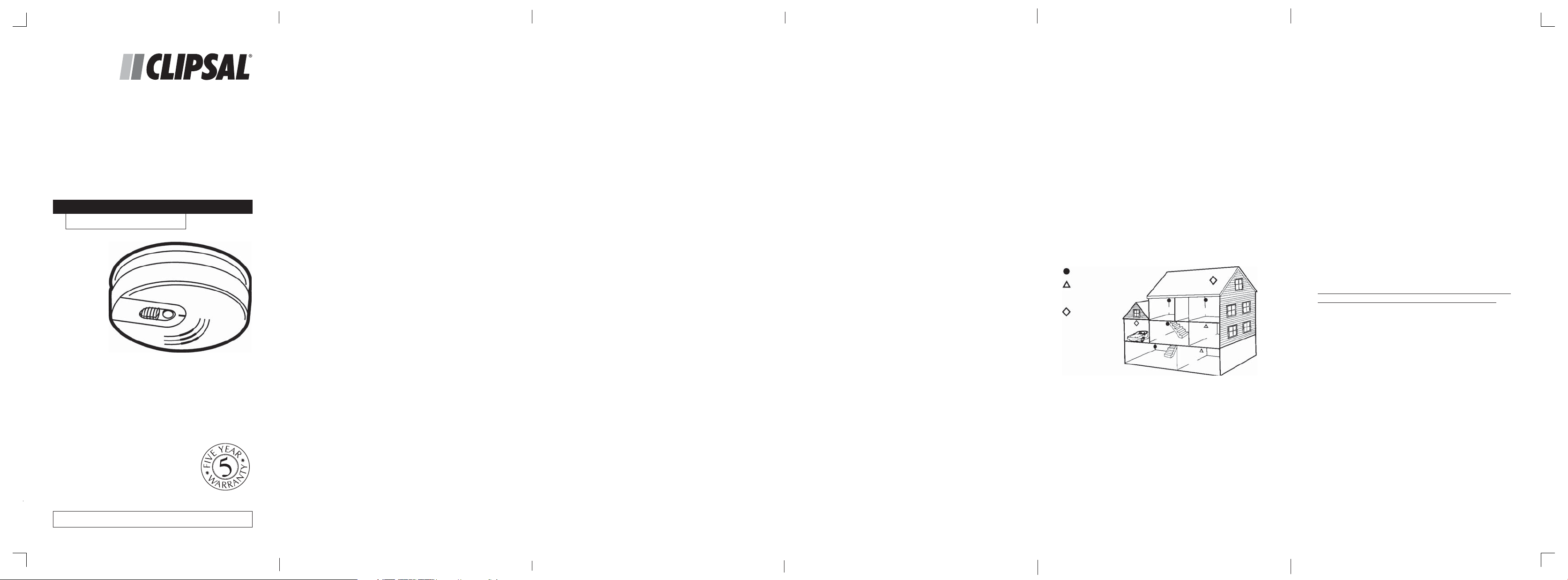
HEAT ALARM LOCATION
Heat alarms are ideal for kitchens, garages, cellars, boiler
rooms, attics and other areas where there are normally high
levels of fumes, smoke or dust which preclude the use of
smoke alarms due to the risk of false alarms. For normalsized houses, two-story houses, fl ats and maisonettes, it is
recommended that the minimum level of protection should
comprise smoke alarms in the hallways and staircases.
This minimum standard necessitates one smoke alarm in
the hallway of a typical bungalow or one smoke alarm on
each level of a two-story house. Heat alarms should not be
used in these circulation areas. If there are, for example,
long hallways, the standard necessitates additional
interconnected smoke alarms.
If, however, the design of the dwelling does not comply
with modern fi re safety standards, or if factors such as the
presence of several young children, of elderly occupants or
disabled people, or of smokers, the use of portable heaters
or solid fuel fi res during the night, or the use of electric
blankets, it is advised that additional detection devices,
installed within rooms, may be necessary.
smoke alarm
photoelectric
smoke alarm
BEDROOM
BATH
heat alarm
GARAGE
LIVING AREA
BASEMENT
BEDROOM
KITCHEN
BOILER ROOM
For best protection, it is recommended that you install
a smoke or heat alarm in every room. In addition, it is
recommended that all smoke and heat alarms should
be interconnected.
Note: Smoke alarms should be installed per AS1670.6
Standard.
Install heat alarm as close to the centre of the ceiling
as possible. If the centre is not practical, mount the heat
alarm no closer than 300mm away from a wall or corner.
In rooms with open joists or beams, all ceiling-mounted
alarms should be located on the bottom of such joists or
beams and not up in joist channels. On sloped, peaked or
5
gabled ceilings, install Heat alarm 300mm from highest
point. If only wall placement is possible, install no further
than 300mm from ceiling.
DO NOT INSTALL HEAT ALARMS
•
Directly over the cooker, stove or oven.
•
In areas with high humidity, like bathrooms or shower
rooms, or areas near dishwashers or washing
machines. Install heat alarms at least 3m away from
these areas if possible.
•
Adjacent to, or directly above, heaters, air-conditioning
vents or ceiling fans.
•
In an area where the temperature may fall below +5°C
or rise above +45°C.
•
Near fl uorescent lights. Electrical “noise” and fl ickering
may affect the operation of the heat alarm.
•
Closer than 300mm to light fi ttings.
•
In such a position that it is diffi cult or dangerous to
reach for testing, maintenance or battery replacement.
HOW TO INSTALL THIS HEAT ALARM
DANGER: electric shock hazards. Turn off power to the
heat alarm circuit at the main distribution board by removing
the fuse or switching the circuit breaker to the off position
and securing it.
WARNING, only a qualifi ed electrician in accordance with
AS/NZS3000 guidelines should install this heat alarm.
Heat alarms should be connected on a single independent,
dedicated circuit at the main distribution board. No
other electrical equipment, except compatible smoke
alarms, should be connected to this circuit. If your home
has residual current device protection on the electrical
installation or on individual circuits, check with a qualifi ed
electrician to make sure that faults on circuits serving
socket outlets or portable appliances cannot cause
interruption to the supply to the heat alarms.
Heat alarms may also be connected to a separate
electrically protected, regularly used local lighting circuit.
However, this will mean that, unless a separate means of
isolation is provided for the heat alarms, it will be necessary
to isolate the lighting circuit every time that there is a need
to isolate the supply to the heat alarms; this may cause
inconvenience or hazards.
6
Page 2
1. Connect the heat alarm as per the fi gure below;
To
fuse or
circuit
breaker
←
A
N
Terminals
Brown
Orange
I
Blue
HEAT
ALARM
755H
2. Close the cover over the terminal block supplied and fi x
the junction box in place.
3. Open the battery compartment door. Connect a
healthy 9V d.c. battery to the battery connector inside
the battery compartment. Be sure the battery is securely
connected. The heat alarm may beep briefl y when the
battery is installed.
4. Close the battery compartment door, snapping it
into place.
5. Attach the connector plug to the pins on the back of the
heat alarm. The plug will only fi t one way, and will snap
into place.
6. Gently tug the connector to be sure it is
attached securely.
7. Position the heat alarm on the mounting plate and turn
it clockwise to lock it into place.
8. Test the heat alarm to verify the 9V d.c., battery
back-up. See “TESTING THE HEAT ALARM”.
NOTE: The heat alarm will not mount the plate if the
battery is not in place.
10. Turn on the power to the heat alarm circuit at the main
distribution board.
11. Test the heat alarm for mains supply operation. See
“TESTING THE HEAT ALARM”.
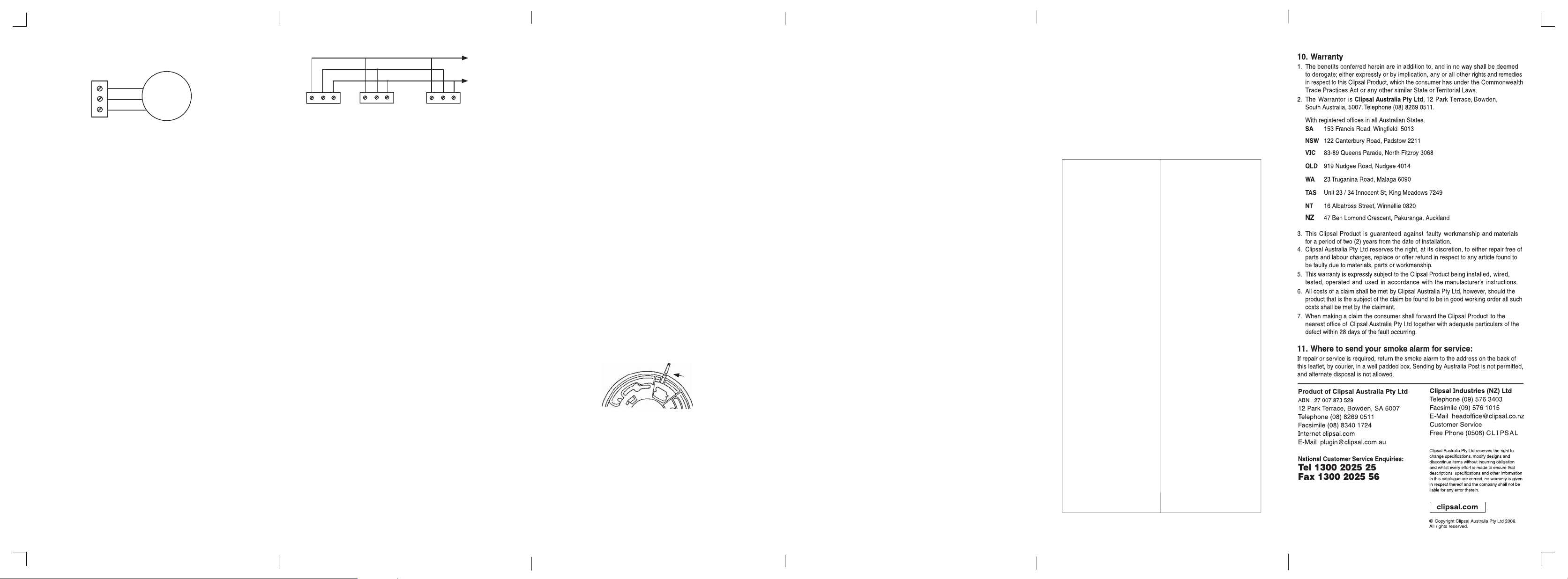
INTERCONNECTING HEAT ALARMS
Use 1.5mm2 minimum solid or stranded cable with a rating
of 240V. When interconnecting heat alarms and / or Smoke
Alarms, the maximum cable length between any two should
be 450m for 1.5mm2 cable (20 ohm loop resistance.)
This Heat alarm may be interconnected with as many as 39
other Clipsal Lifesaver 755 Series Heat and Smoke Alarms.
Do not connect to any other type of model of Heat alarm or
Smoke Alarm. Connect all interconnected Heat and Smoke
Alarms to a single fi nal circuit.
Connecting the switch wire terminal in any other way to that
shown in this instruction may result in damage to the Heat
alarm, failure to operate or an electrical shock hazard. It
also voids the warranty.
7
FUSE OR
Brown
AI
Blue
N
•
•
•
A
N
I
Active
•
CIRCUIT
BREAKER
Neutral
•
A
N
I
RED AND GREEN LED INDICATORS
This heat alarm features a red and green LED indicator
that can be seen through the clear light pipe on the top of
alarm. The LEDs indicate the following:
GREEN ON - a.c. power is present.
OFF- a.c. power is not present.
RED BLINKS ONCE A MINUTE - d.c. power
is present indicating normal operation.
OFF- d.c. power is not present.
BLINKS ONCE A SECOND and unit is
sounding alarm - senses temperature of
73° to comply within the range of 58°C to
88°C per AS1603.3-1996.
OFF and unit is sounding alarm - Another
interconnected smoke/heat alarm in the
network has alarmed.
TESTING THE HEAT ALARM
WARNING, Test each heat alarm and smoke alarm to
be sure that each is installed correctly and is operating
properly. Stand at arm’s length from the heat alarm when
testing. The alarm sounder is loud to alert you to an
emergency and can be harmful to hearing. Test the heat
alarm weekly and upon returning from holiday, or when the
house has been unoccupied for several days.
Test all heat alarms weekly by doing the following:
1. Check the Test push-button. A constant ON green light
indicates the Heat alarm is receiving a.c. power.
2. Firmly depress the Test push-button for at least fi ve (5)
seconds. The Heat alarm will sound a loud beep. The
alarm may sound for up to ten (10) seconds after the
Push-to-Test button is released.
NOTE: If heat alarms are interconnected, all heat
alarms should sound an alarm within three (3) seconds
after any Test button is pushed and the tested heat
alarm sounds.
3. If the heat alarm does not sound, turn off the power to
the heat alarm circuit at the main distribution board
and check the wiring. Retest the heat alarm.
4. Do not apply excessive force to the Test push-button.
Doing so may damage the unit and void the warranty.
5. Never use an open fl ame of any type to test the alarm.
You may damage the alarm or set fi re to your home.
Operating the Test push-button will check for
correct functioning.
8
WARNING, If the heat alarm sounds, and the heat alarm is
not being tested, the heat alarm is activated and requires
your immediate attention and action.
MAINTENANCE AND CLEANING
1. If a zinc oxide or alkaline battery is used, the battery
should be renewed at least once a year.
2. Heat alarms are virtually maintenance free. However,
vacuuming the unit at least once every six months will
remove dust.
3. Wipe the enclosure clean with a water moistened
cloth. Do not immerse this unit or use household
cleaners. Do not apply paint or spray with any liquid.
4. All Clipsal heat alarms are manufactured and tested
to rigorous quality standards and have a minimum life
expectancy of 10 years. However, for your safety we
recommend replacing your Heat alarm with a new
Clipsal unit after 10 years. This will ensure that you are
always protected by a heat alarm that is operating
within the limits of its life expectancy.
DANGER, electric shock hazard. Turn off the a.c., supply to
the heat alarm at the main distribution board by removing
the fuse or switching the appropriate circuit breaker to the
OFF position before replacing the battery or cleaning the
heat alarm.
FITTING TAMPER PIN
A tamper resistant feature on the heat alarm may be used
to precent unauthorised removal of the heat alarm from the
mounting plate.
•
From the back of the heat alarm remove the mounting
plate. Twist out and remove one of the pins moulded
into the plate. (Both pins are exactly the same).
•
Position heat alarm to mounting plate and turn
clockwise to lock into place. To engage tamper resist
feature, insert pin into notch on edge of heat alarm.
Insert pin here
BATTERY REPLACEMENT
Always turn off the a.c., supply to the heat alarm before
replacing the battery. Replace the battery at least once
annually, or immediately when the low battery signal
sounds once a minute, even though the heat alarm is
receiving a.c. power. Use only the following batteries as
replacements in this heat alarm: Eveready 216, 522, 1222,
Duracell MN 1604 or Ultralife U9VL - J.
The battery should only be relaced by a qualifi ed electrician
or similarly qualifi ed person.
9
Warning. Do not use any other type of battery except as
specifi ed in this manual. Do not use rechargeable batteries.
1. Turn off the a.c. power supply to the heat alarm at the
main distribution board.
2. Turn the heat alarm counterclockwise to detach the
alarm. (Remove tamper pin if fi tted.)
3. Gently pull down the heat alarm. Be careful not to
separate any wire connections.
4. Pull out the connector plug from the back of the
heat alarm.
5. Remove the battery from the compartment. Disconnect
the drained battery from the battery compartment
and discard.
6. Connect a new, healthy 9V d.c. battery to the connector.
The battery will only fi t one way. Be sure the battery
connector is securely attached to the battery terminals.
7. Place the battery into the battery compartment
8. Close the battery compartment door. Push down until it
snaps into place.
9. Using the Push-to-Test button, test the heat alarm to
verify 9V d.c. battery back-up. See “TESTING THE
HEAT ALARM”.
10. Replace the connector plug. The connector will “snap”
into place. Gently tug the connector to be sure it is
attached properly.
11. Reattach the heat alarm to the mounting plate by
turning the heat alarm clockwise until it snaps
into place.
12. Turn on the a.c. power and test the heat alarm using
the Push-to-Test button. See “TESTING THE
heat alarm”.
REPAIRS AND SERVICE
This heat alarm has no user serviceable parts. Dangerous
voltages are contained within, so do not attempt to repair
this unit yourself. Instead, this heat alarm should be
returned to the supplier for service.
WHAT TO DO IF THE ALARM SOUNDS
1. Leave immediately, following your family’s escape plan.
2. As you leave, don’t open any inside doors without fi rst
feeling its surface. If the door is hot, or if you see smoke
coming through the cracks, do not open the door. Use
an alternative exit.
3. If the inside of the door is cool, place your shoulder
against it, open it slightly and be ready to slam it shut
if heat and smoke rush in.
4. If the air is smokey, stay as close to the fl oor
as possible.
5. Breathe shallowly through a cloth, which if possible
should be wet.
10
6. Once outside, go to your pre-selected assembly area
and make sure everyone else is there.
7. Call the Fire Service from a neighbour’s home - never
from your own.
8. Do not return to your home until fi re offi cials give you
permission to do so.
For further information on fi re safety, contact your local Fire Service.
TROUBLESHOOTING
To be carried out by a licensed electrician or similarly
qualifi ed person.
PROBLEM
Heat alarm does not
sound when tested.
Push test button for at
least fi ve (5) seconds
while testing!
Heat alarm beeps
about once a minute.
See “Battery
Replacement”
Heat alarm sounds
unwanted alarms.
Interconnected heat
alarms do not sound
when system
is tested.
SOLUTION
1. Check that a.c. power
is turned on.
2. Turn off power Remove
heat alarm from
mounting
plate and:
a. Check that connector
plug is securely
attached.
b. Check that battery is
properly attached
to connector.
c. Vacuum heat alarm.
Turn off a.c. power and
replace battery
in the “MAINTENANCE
AND CLEANING” section.
Hire an electrician to
move heat alarm to a new
location. See the “HEAT
ALARM LOCATION” and
“DO NOT INSTALL HEAT
ALARMS” sections
of this manual.
1. Press and hold button
for at least three
seconds after the fi rst
unit sounds.
2. Turn off a.c. power or
circuit breaker and
check the interconnect
wiring.
See "INTERCONNECTING
HEAT ALARMS" section
of this manual.
11
F1516/ 02
2547 7 25
12
 Loading...