

Page 1
1
Use this manual to install your Firex Multi-Function Relay Module (MFRM). This module can be used only with the following Firex Smoke, Smoke/CO,
and CO alarm models (and item number series): G-6 (406 series), G-18 (418 series), PG (484 series), FADC (4618 and 5000 series), AD (4418 series),
ADC (4518 series), ADH (5700 series), GC (4121 series), PAD (4480 series), FPAD (4580 series), FADCM (12000 series), GCM (12400 series), COE (10000
series), or COEA (10400 series). These are low-voltage interconnect alarms with a YELLOW interconnect wire.
WARNING: A qualified licensed electrician should make all connections following the National Electrical Code and any
other local building codes.
CAUTION: Do not use with any other type of Firex alarm or any other manufacturer’s alarms. Doing so will
permanently damage the MFRM. Firex smoke alarms with ORANGE interconnect wires ARE NOT
COMPATIBLE with this module.
SPECIFICATIONS
The MFRM has a single-pole double-throw (SPDT) relay with contacts rated at 120 Volts AC, 5 Amps. The normally-closed (NC) contact (RED wire)
opens upon alarm. The normally-open (NO) contact (BLUE wire) closes upon alarm. The GRAY wire is the relay’s common wire.
The MFRM current consumption is 0.005 Amps AC maximum.
The MFRM can interconnect with up to 18 compatible devices (maximum of twelve (12) Firex smoke alarms and six (6) Firex CO and/or heat alarms).
More than the NFPA and UL maximum interconnections may cause problems.
NOTE: The total number of alarms in an interconnected circuit depends on the specific Firex alarm model used.
CAUTION: The MFRM should NOT be used to increase the maximum number of Firex alarms permitted in multiple
station operation (refer to the Firex alarm manual).
CAUTION: The MFRM will not operate without AC power.
INSTALLATION INSTRUCTIONS
Install the MFRM in its own separate junction box. A four-inch square by two-inch deep box is typically used.
A qualified licensed electrician should
make all connections following the National Electrical Code and any other local building codes.
1. Turn off main power at the circuit breaker or fuse box to the branch alarm circuit.
2. Install and wire your Firex AC alarms as shown in their owners’ manuals.
3. Connect the WHITE wire of the MFRM to the WHITE (neutral) wire of the AC line.
4. Connect the BLACK wire of the MFRM to the BLACK (hot) wire of the AC line.
5. Connect the YELLOW wire of the MFRM to the interconnect line.
6. Connect the GRAY (common) wire of the MFRM to the BLACK (hot) wire of the controlled AC circuit, if you are using line voltage to control the
secondary device.
7. Connect the RED (NC) wire of the MFRM to the load of the controlled AC circuit.
OR
Connect the BLUE (NO) wire of the MFRM to the load of the controlled AC circuit.
8. Connect the ORANGE (select) wire of the MFRM as follows:
• To the WHITE (neutral) wire of the AC line if the MFRM should respond to both CO and smoke alarms.
• To the BLACK (hot) wire of the AC line if the MFRM should respond to only CO alarms.
• Cap, tape off, or attach a wire nut to the ORANGE (select) wire if the MFRM should respond to smoke alarms only.
9. Install the MFRM in the junction box.
10. If you are connecting this relay with models FADCM, GCM, COE, or COEA (refer to item number series at the beginning of these instructions),
you must perform an INTERCONNECT TEST at the alarm in order to verify the correct operation of the relay throughout the
interconnected system.
NOTES:
1. Cap each unused wire with a wire nut.
2. The controlled branch circuit is typically a separate circuit from the alarm branch circuit.
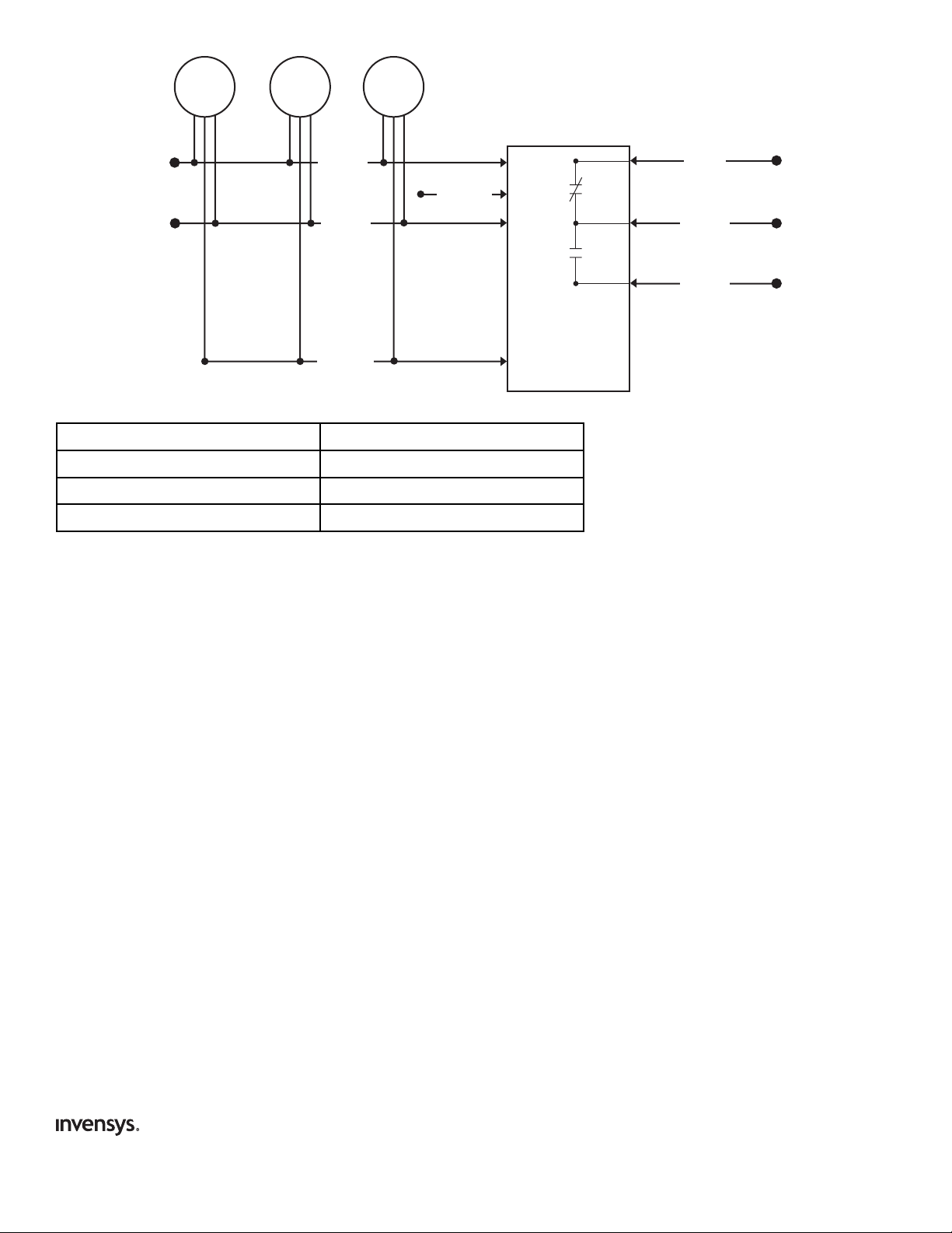
3. The wiring diagram on page 2 is an example showing how to connect the MFRM into the alarm interconnect circuit.
MULTI-FUNCTION
RELAY MODULE No. 501
READ THESE INSTRUCTIONS CAREFULLY BEFORE
INSTALLING THIS MODULE!
Page 2
2
Select (Orange Wire) Connection Chart
INVENSYS CONTROLS AMERICAS LIMITED WARRANTY
Invensys Controls Americas warrants to the original consumer purchaser each new Firex Multi-Function Relay Module to be free from defects in
material and workmanship under normal use and service for a period of one (1) year from date of purchase. Invensys Controls Americas agrees to
repair or replace, at its option, any Firex Multi-Function Relay Module found defective provided that it is returned with postage prepaid and with
proof of purchase date, to Invensys Controls Americas. This Warranty does not cover damage resulting from accident, misuse or abuse or lack of
reasonable care of the product. This Warranty is in lieu of all other express warranties, obligations or liabilities.
THE IMPLIED WARRANTIES OF MERCHANTABILITY AND FITNESS FOR A PARTICULAR PURPOSE ARE LIMITED TO A PERIOD OF ONE (1) YEAR FROM
PURCHASE DATE.
Some states do not allow limitations on how long an implied warranty lasts, so the above limitation may not apply to you. In no case shall Invensys
Controls Americas be liable for any consequential damages for breach of this or any other warranty, express or implied, whatsoever. Some states do
not allow the exclusion of consequential damages, so the above exclusion may not apply to you. This Warranty gives you specific legal rights, and
you may also have other legal rights which vary from state to state.
Instructions for product return:
Describe the problem with the MFRM on your letterhead and place the letter together with the MFRM in a padded carton with return postage
prepaid. Send these items to:
IN THE U.S.: IN CANADA:
Invensys Controls Americas Invensys Controls Americas
Product Service Department Product Service Department
28C Leigh Fisher Blvd 3505 Laird Road – Unit #14
El Paso, TX 79906 Mississauga, Ontario L5L 5Y7
Firex
110-1176B
Responds to: Connected to:
CO Alarm Only Hot (Black Wire)
Smoke Alarm Only Not connected (cap, tape, or wire nut)
Both CO and Smoke Alarm Neutral (White Wire)
Controls Americas
191 E. North Avenue
Carol Stream, IL 60188
Technical Service Telephone +1 800 445 8299
Technical Service Facsimile +1 630 260 7243
technicalservice@invensys.com
www.icca.invensys.com
©2006 Invensys Controls Americas
Alarm
Firex
Alarm
HOT
(BLACK WIRE)
NEUTRAL
(WHITE WIRE)
INTERCONNECT
(YELLOW WIRE)
Firex
Alarm
SELECT
(ORANGE WIRE)
MULTI-FUNCTION
RELAY MODULE
MODEL 501
NORMALLY CLOSED
(RED WIRE)
COMMON
(GRAY WIRE)
NORMALLY OPEN
(BLUE WIRE)
Page 3

3
Utilisez ce manuel pour installer votre module de relais multifonctions Firex (MFRM). Ce module est uniquement destiné aux modèles (et numéros de
série) de détecteurs de fumée et/ou de monoxyde de carbone Firex suivants : G-6 (série 406), G-18 (série 418) , PG (série 484), FADC (séries 4618 et
5000), AD (série 4418), ADC (série 4518), ADH (série 5700), GC (série 4121), PAD (série 4480), FPAD (série 4580), FADCM (série 12000), GCM (série
12400), COE (série 10000), ou COEA (série 10400). Ce sont des alarmes d’interconnexion sous basse tension avec un fil d'interconnexion JAUNE.
MISE EN GARDE : Toutes les connexions devraient être faites par un électricien agréé qualifié en suivant le Code
national de l'électricité et tout autre code du bâtiment en vigueur.
ATTENTION : N’utilisez avec aucun autre type d’alarme Firex ni avec aucune alarme d'un autre fabricant. Cela détruirait le
MFRM. Les détecteurs de fumée munis d’un fil d’interconnexion ORANGE NE SONT PAS COMPATIBLES
avec ce module.
CARACTÉRISTIQUES
Le MFRM est muni d'un relais unipolaire bidirectionnel dont les contacts sont prévus pour un courant nominal de 120 Volts en courant alternatif, 5
Ampères. Le contact normalement fermé (NC) (fil ROUGE) s’ouvre dès l’alarme. Le contact normalement ouvert (NO) (fil BLEU) se ferme dès l’alarme.
Le fil GRIS est le fil commun du relais.
La consommation de courant du MFRM est de 0,005 Ampères maximum.
Le MFRM peut s’interconnecter avec un maximum de 18 appareils compatibles (un maximum de douze (12) détecteurs de fumée Firex et six (6)
détecteurs Firex de monoxyde de carbone et/ou de chaleur). Un nombre d’interconnexions supérieur au maximum de la NFPA et du UL peut créer
des problèmes.
REMARQUE : Le nombre total d’alarmes dans un circuit interconnecté dépend du modèle spécifique de l’alarme Firex utilisée.
ATTENTION : Le MFRM ne doit pas s’utiliser pour dépasser le maximum d’alarmes Firex autorisé pour un
fonctionnement en multiposte (voir le manuel d’alarme Firex).
ATTENTION : Le MFRM ne fonctionne pas en l’absence de courant alternatif.
INSTRUCTIONS D'INSTALLATION
Installez le MFRM dans son propre boîtier de raccordement. De manière typique, on utilise un boîtier carré de 10 cm avec 5 cm de profondeur.
Toutes les connexions devraient être faites par un électricien agréé qualifié en suivant le Code national de l'électricité et tout autre code du bâtiment en vigueur.
1. Coupez l’alimentation électrique principale du circuit de dérivation de l’alarme au niveau du disjoncteur ou du coffret à fusibles.
2. Installez et branchez vos alarmes Firex à courant alternatif en suivant les instructions fournies dans leur guide d'entretien.
3. Connectez le fil BLANC du MFRM au fil BLANC (neutre) de la ligne de courant alternatif.
4. Connectez le fil NOIR du MFRM au fil NOIR (chargé) de la ligne de courant alternatif.
5. Connectez le fil JAUNE du MFRM au fil JAUNE de la ligne d'interconnexion.
6. Connectez le fil GRIS (commun) du MFRM au fil NOIR (chargé) du circuit de courant alternatif contrôlé si vous utilisez la tension du secteur
pour contrôler le dispositif secondaire.
7. Connectez le fil ROUGE (normalement fermé) du MFRM à la charge du circuit de courant alternatif contrôlé.
OU
Connectez le fil BLEU (normalement ouvert) du MFRM à la charge du circuit de courant alternatif contrôlé.
8. Connectez le fil ORANGE (sélection) du MFRM de la manière suivante :
• Au fil BLANC (neutre) du secteur si le MFRM doit répondre à la fois aux alarmes de monoxyde de carbone et de fumée.
• Au fil NOIR (chargé) du secteur si le MFRM ne doit répondre qu’aux alarmes de monoxyde de carbone.
• Mettez un capuchon ou isolez avec du ruban adhésif le fil ORANGE (sélection) si le MFRM ne doit répondre qu’aux alarmes de fumée.
9. Installez le MFRM dans le boîtier de raccordement.
10. Si vous raccordez ce relais aux modèles FADCM, GCM, COE, ou COEA (référez-vous aux numéros de série donnés au début de ces
instructions), vous devez effectuer un TEST D’INTERCONNEXION de l’alarme afin de vérifier le bon fonctionnement du relais à travers tout le
système interconnecté.
REMARQUES :
1. Recouvrez tout fil non utilisé avec un capuchon.
2. Le circuit de dérivation contrôlé est généralement un circuit séparé de celui du circuit de dérivation de l’alarme.
3. Le schéma de câblage de la page 2 donne un exemple de la façon de connecter le MFRM dans le circuit d’alarme interconnecté.
MODULE DE RELAIS
MULTIFONCTIONS N° 501
VEUILLEZ LIRE ATTENTIVEMENT L’ENSEMBLE DU
MANUEL AVANT D’INSTALLER CE RELAIS!
Page 4

4
Sélection (fil orange) : diagramme de connexion
GARANTIE LIMITÉE DE INVENSYS CONTROLS AMERICAS
Invensys Controls Americas garantit au consommateur acheteur d’origine que chaque nouveau module de relais multifonctions FIREX est dépourvu
de tout défaut de matériau et de main d’oeuvre dans des conditions normales d’utilisation et d’entretien pendant une période de un (1) an à compter
de la date d’achat. Invensys Controls Americas accepte de réparer ou de remplacer, à sa discrétion, tout module de relais multifonctions FIREX qui
s’avère défectueux à condition que celui-ci soit retourné franco de port à Invensys Controls Americas avec un justificatif de la date d’achat. Cette
garantie ne prend pas en charge les dégâts résultants de tout accident, mauvaise utilisation ou utilisation abusive ou manque de soin raisonnable du
produit. Cette garantie annule et remplace toutes les autres garanties expresses, obligations ou responsabilités.
LES GARANTIES IMPLICITES DE QUALITÉ MARCHANDE ET D’ADAPTATION À UNE UTILISATION PARTICULIÈRE SONT LIMITÉES À UNE DURÉE DE
UN (1) AN À COMPTER DE LA DATE D’ACHAT.
Certaines provinces ne permettant pas de restriction sur la durée d’une garantie implicite, il est possible que les restrictions ci-dessus ne
s’appliquent pas dans votre cas. Invensys Controls Americas ne pourra en aucun cas être tenue responsable en cas de dommages indirects en cas
d’infraction de cette garantie ou de toute autre garantie, expresse ou implicite, quelle qu’elle soit. Certaines provinces ne permettant pas l’exclusion
des dommages indirects, il est possible que l’exclusion ci-dessus ne s’applique pas dans votre cas. La présente garantie vous confère des droits
juridiques particuliers et vous pouvez également jouir d’autres droits qui varient d’une province à l’autre.
Instructions pour le retour du produit :
Décrivez le problème associé au MFRM sur du papier portant votre en-tête et placez la lettre avec le MFRM dans un carton matelassé avec le port
de retour payé. Envoyez ces articles à :
AUX ÉTATS-UNIS : AU CANADA :
Invensys Controls Americas Invensys Controls Americas
Product Service Department Product Service Department
28C Leigh Fisher Blvd 3505 Laird Road – Unit #14
El Paso, TX 79906 Mississauga, Ontario L5L 5Y7
Alarme
110-1176B
Répond à : Connecté à :
Alarme CO seulement Charge (fil noir)
Alarme de fumée seulement Non connecté (capuchon ou ruban isolant)
À la fois alarmes de CO et de fumée Neutre (fil blanc)
Controls Americas
191 E. North Avenue
Carol Stream, IL 60188
Service technique : Téléphone +1 800 445 8299
Service technique : Téléfax +1 630 260 7243
technicalservice@invensys.com
www.icca.invensys.com
©2006 Invensys Controls Americas
Firex
Alarme
Firex
INTERCONNEXION
CHARGE
(FIL NOIR)
NEUTRE
(FIL BLANC)
(FIL JAUNE)
Alarme
Firex
SÉLECTION
(FIL ORANGE)
MODULE DE RELAIS
MULTIFONCTIONS
MODÈLE 501
NORMALEMENT FERMÉ
(FIL ROUGE)
COMMUN
(FIL GRIS)
NORMALEMENT OUVERT
(FIL BLEU)
Page 5

5
Use este manual para instalar el módulo relé multifunción Firex (Multi-Function Relay Module, MFRM). Este módulo sólo puede utilizarse con los
siguientes modelos de alarma de humo Firex, alarma de humo/monóxido de carbono (CO) y alarma de CO (y el número de serie): G-6 (serie 406), G-18
(serie 418), PG (serie 484), FADC (serie 4618 y 5000), AD (serie 4418), ADC (serie 4518), ADH (serie 5700), GC (serie 4121), PAD (serie 4480), FPAD (serie
4580), FADCM (serie 12000), GCM (serie 12400), COE (serie 10000) o COEA (serie 10400). Éstas son alarmas de interconexión de bajo voltaje con un
cable AMARILLO.
ADVERTENCIA: Todas las conexiones deben ser realizadas por un electricista calificado autorizado, de acuerdo con el
Código Eléctrico Nacional y con los códigos de construcción locales.
PRECAUCIÓN: No utilice este módulo con ningún otro tipo de alarma Firex ni con ninguna alarma de otro fabricante.
Si lo hace, dañará el MFRM de forma permanente. Las alarmas de humo Firex con cable de interconexión
ANARANJADO NO SON COMPATIBLES con este módulo.
ESPECIFICACIONES
El MFRM tiene un relé de polo simple y doble tiro (Single-pole Double-throw, SPDT) con contactos de 120 Voltios AC, 5 Amp. El contacto (cable
ROJO) normalmente cerrado (NC) se abre cuando se dispara la alarma. El contacto (cable AZUL) normalmente abierto (NO) se cierra con la alarma.
El cable GRIS es el cable común del relé.
El consumo de corriente del MFRM es de 0.005 Amp AC máximo.
El MFRM puede interconectarse hasta con 18 dispositivos compatibles (máximo doce [12] alarmas de humo Firex y seis [6] alarmas de CO y/o de
calor Firex). Si se hacen más interconexiones que las permitidas por la Asociación Nacional de Protección contra Incendios (National Fire
Protection Association, NFPA) y Underwriters Laboratories (UL) pueden ocurrir problemas.
NOTA: El número total de alarmas en un circuito interconectado depende del modelo específico de alarma Firex utilizado.
PRECAUCIÓN: El MFRM NO debe utilizarse para aumentar la cantidad máxima de alarmas Firex permitidas para la
operación de estaciones múltiples (consulte el manual de alarmas Firex).
PRECAUCIÓN: El MFRM no funcionará sin corriente AC.
INSTRUCCIONES DE INSTALACIÓN
Instale el MFRM en su propia caja de conexiones independiente. Generalmente se utiliza una caja de cuatro pulgadas cuadradas por dos pulgadas
de profundidad.
Todas las conexiones deben ser realizadas por un electricista calificado autorizado, de acuerdo con el Código Eléctrico Nacional
y con los códigos de construcción locales.
1. Desactive la corriente principal al circuito de alarma derivado en el disyuntor o en la caja de fusibles.
2. Instale y conecte las alarmas AC Firex como se muestra en los manuales del propietario.
3. Conecte el cable BLANCO del MFRM con el cable BLANCO (neutro) de la línea AC.
4. Conecte el cable NEGRO del MFRM con el cable NEGRO (vivo) de la línea AC.
5. Conecte el cable AMARILLO del MFRM a la línea de interconexión.
6. Conecte el cable GRIS (común) del MFRM al cable NEGRO (vivo) del circuito AC controlado, si está utilizando voltaje de línea para controlar el
dispositivo secundario.
7. Conecte el cable ROJO (NC) del MFRM a la carga del circuito AC controlado.
O BIEN
Conecte el cable AZUL (NO) del MFRM a la carga del circuito AC controlado.
8. Conecte el cable ANARANJADO (selección) del MFRM del siguiente modo:
• Al cable BLANCO (neutro) de la línea AC si el MFRM debe responder tanto a las alarmas de CO como a las alarmas de humo.
• Al cable NEGRO (vivo) de la línea AC si el MFRM debe responder sólo a las alarmas de CO.
• Remate, encinte o sujete una tuerca al cable ANARANJADO (selección) si el MFRM debe responder sólo a las alarmas de humo.
9. Instale el MFRM en la caja de conexiones.
10. Si conecta este relé con los modelos FADCM, GCM, COE o COEA (remítase a los números de serie al comienzo de estas instrucciones), debe
realizar una PRUEBA DE INTERCONEXIÓN en la alarma para verificar la correcta operación del relé en todo el sistema interconectado.
NOTAS:
1. Remate todos los cables que no utilizan tuercas de cable.
2. El circuito derivado controlado generalmente es un circuito distinto del circuito de alarma derivado.
3. El diagrama de cableado de la página 2 muestra cómo conectar el MFRM con el circuito de interconexión de la alarma.
MÓDULO RELÉ
MULTIFUNCIÓN No. 501
¡LEA ESTAS INSTRUCCIONES CON ATENCIÓN
ANTES DE INSTALAR EL MÓDULO!
Page 6

6
Cuadro de conexión de selección (cable anaranjado)
GARANTÍA LIMITADA DE INVENSYS CONTROLS AMERICAS
Invensys Controls Americas garantiza al comprador consumidor original que todos los módulos relé multifunción Firex no tendrán defectos de
materiales ni en su fabricación bajo condiciones normales de uso y servicio por un período de un (1) año a partir de la fecha de compra. Invensys
Controls Americas acuerda reparar o reemplazar, a su elección, cualquier módulo relé multifunción Firex defectuoso siempre que se realice la
devolución con los gastos de correo prepagados con anticipación y enviando la fecha del comprobante de compra a Invensys Controls Americas.
Esta garantía no cubre los daños ocasionados por accidentes, mal uso, abuso o falta de cuidado razonable del producto. Esta garantía prevalece
sobre todas las otras garantías, obligaciones o responsabilidades legales explícitas.
LAS GARANTÍAS IMPLÍCITAS DE COMERCIABILIDAD Y APTITUD PARA UN PROPÓSITO PARTICULAR ESTÁN LIMITADAS A UN PERÍODO DE UN (1)
AÑO A PARTIR DE LA FECHA DE COMPRA.
Algunos estados no permiten las limitaciones en lo que respecta a la duración de la garantía implícita, por lo que posiblemente la limitación
mencionada anteriormente no aplique en su caso. Bajo ninguna circunstancia Invensys Controls Americas será responsable de ningún daño directo
provocado por la violación de ésta o cualquier otra garantía, explícita o implícita, en absoluto. Algunos estados no permiten la exclusión de daños
directos, por lo que posiblemente la exclusión mencionada anteriormente no aplique en su caso. Esta garantía le otorga derechos legales
específicos y es posible que también le otorgue otros derechos legales que varían de estado a estado.
Instrucciones para la devolución del producto:
Describa el problema del MFRM en el asunto de su carta y envíela junto con el MFRM en una caja con material de protección y el porte de ida y
vuelta prepagado. Envíe el producto a:
IN THE U.S.: IN CANADA:
Invensys Controls Americas Invensys Controls Americas
Product Service Department Product Service Department
28C Leigh Fisher Blvd 3505 Laird Road – Unit #14
El Paso, TX 79906 Mississauga, Ontario L5L 5Y7
Alarma
110-1176B
Responde a: Conectado a:
Sólo alarma de CO Vivo (cable negro)
Sólo alarma de humo No conectado (remate, encinte o coloque una tuerca de cable)
Alarma de CO y alarma de humo Neutro (cable blanco)
Controls Americas
191 E. North Avenue
Carol Stream, IL 60188
Número de teléfono del servicio técnico +1 800 445 8299
Número de fax del servicio técnico +1 630 260 7243
technicalservice@invensys.com
www.icca.invensys.com
©2006 Invensys Controls Americas
Firex
Alarma
Firex
(CABLE NEGRO)
(CABLE BLANCO)
INTERCONECCIÓN
(CABLE AMARILLO)
VIVO
NEUTRO
Alarma
Firex
SELECCIÓN
(CABLE ANARANJADO)
MÓDULO RELÉ
MULTIFUNCIÓN
MODELO 501
NORMALMENTE CERRADO
(CABLE ROJO)
COMÚN
(CABLE GRIS)
NORMALMENTE ABIERTO
(CABLE AZUL)
 Loading...