

Kidco G3001 User Manual [en, es, fr]
USER GUIDE
GUIDE D'UTILISATION
GUÍA DEL USUARIO
G3001G3000
®
1013 Technology Way, Libertyville, IL 60048
800.553.5529
www.kidco.com
®
Auto Close Conf igureGate
CUSTOM FIT INSTALLATION
Fits openings 84” • Optional 9” and 24” extensions available for larger areas
Barrière adaptée à des ouvertures de 213 cm • Rallonges de 22,8 et 60,9 cm
disponibles en option pour les grandes surfaces
Para aberturas de 84" • Hay disponibles extensiones opcionales de 9” y 24" para áreas más grandes
™
USER GUIDE
G3000/G3001
Auto Close Conf igureGate
™
G3000/G3001
Auto Close Conf igureGate
™
LISTA DE PIEZAS Y MÉTODO DE PAGO
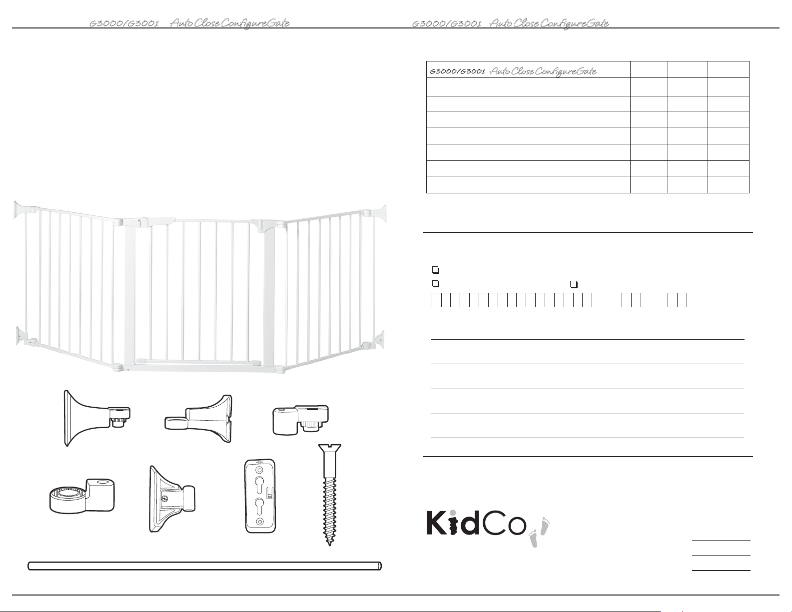
Parts list
A 24” Section (2)
B 30” Walk-Through Door Section
C Upper Post Wall Bracket
D Upper Receiver Wall Bracket
E Lower Post Wall Bracket
F Lower Receiver Wall Bracket
G Sliding Wall Bracket Assembly (2)
H Wall Plate (4-assembled to parts C, D, and G)
I Wood Screw (8) (1 3/8”)
J Wall Mount Bar (2)
B
G3000/G3001
Auto Close Conf igureGate
C Soporte superior del poste de montaje en la pared
D Soporte receptor superior de montaje en la pared
E Soporte inferior del poste de montaje en la pared
F Soporte receptor inferior de montaje en la pared
G Conjunto de soportes deslizantes de montaje en la pared
H Placa para la pared
J Barra de montaje en la pared
AA
MÉTODO DE PAGO Por favor no envíe dinero en efectivo
™
Precio G3000 G3001
$5.00
$5.00
$5.00
$5.00
$5.00
$2.00
$7.00
Cheque/Giro postal adjunto (pagadero a: KidCo, Inc.)
VISA (13 ó 16 dígitos) Mastercard (16 dígitos)
Mes Año
Número de la tarjeta de crédito Fecha de vencimiento (requerida)
Firma del portador de la tarjeta
Fecha
Por favor escriba en letras de molde el nombre del portador de la tarjeta
C D E
Nombre
Domicilio residencial
Ciudad
Estado
N.º telefónico diurno
Unidad
Código postal
F G H I
CARGOS POR ENVÍO Y MANEJO
Si el pedido incluye tubos de extensión,
®
J
1013 Technology Way
Libertyville, IL 60048-5349
2
barras o pivotes, añada $8.00.
Para todos los demás pedidos, añada $5.00.
Cantidad del pedido
Envío y manejo
Total
$
$
$
23
USER GUIDE
Assembly
G3000/G3001
Auto Close Conf igureGate
™
G3000/G3001
Auto Close Conf igureGate
™
PARTS PRICE LIST AND METHOD OF PAYMENT
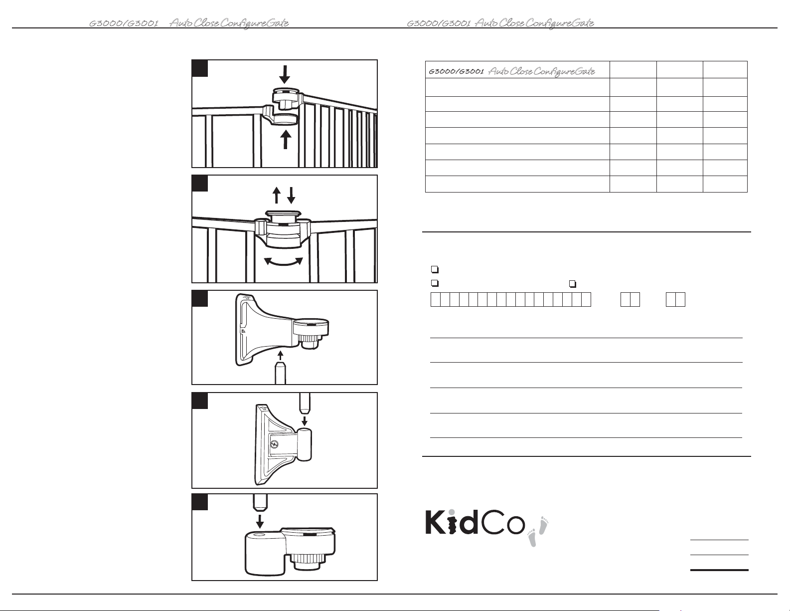
1 To connect two sections, place hinge
posts over the center of the next section’s
hinge receivers and press down until a click is
heard. Continue adding more sections the
same way. Optional 9” and 24” sections are
available for purchase for larger areas or to
construct a free standing enclosure.
NOTE: The walk through door section can be
positioned anywhere within the layout of the
gate. For the auto close door feature to work
properly the entire gate must be on a level
surface, otherwise the door may have to be
manually pushed shut.
2 Once all sections have been assembled
lift all locking caps into the raised unlocked
position (a) and adjust the angle of each
section until desired configuration is achieved
(b). Push down on all locking caps (c). If
locking cap is difficult to lift, gently rotate
sections to relieve pressure and/or carefully
insert a coin or slotted screwdriver in notch
(d) between cap and housing, and push up.
3 Insert wall mount bar into upper
post bar bracket. The wall plate is already
attached to the upper post bar bracket.
4 Insert bar into sliding wall bracket
assembly with locking tabs lined up on right
side and arrows facing up.
1
G3000/G3001
Auto Close Conf igureGate
C Upper Post Wall Bracket
D Upper Receiver Wall Bracket
E Lower Post Wall Bracket
F Lower Receiver Wall Bracket
G Sliding Wall Bracket Assembly
H Wall Plate
2
(a) (c)
(d)
J Wall Mount Bar
™
Price G3000 G3001
$5.00
$5.00
$5.00
$5.00
$5.00
$2.00
$7.00
METHOD OF PAYMENT Please do not send cash
(b)
3
Check/Money Order enclosed (payable to: KidCo, Inc.)
VISA (13 or 16 digits) Mastercard (16 digits)
Mo Yr
Credit card account number Expiration date (required)
Signature of cardholder
Please print name of cardholder
Name
Date
Daytime phone number
4
Street address
City
State
Unit
Zip
5 Insert bar into lower post bar housing.
4
SHIPPING AND HANDLING CHARGES
5
®
1013 Technology Way
Libertyville, IL 60048-5349
If order includes extension tubes,
bars or spindles add $8.00
All others add $5.00
Order amount
Shipping & handling
Total
$
$
$
21
USER GUIDE
G3000/G3001
Auto Close Conf igureGate
™
G3000/G3001
Auto Close Conf igureGate
™
GUÍA DEL USUARIO
Installation
NOTE: Move ConfigureGate to desired
location. Sections may need to be adjusted
again for proper fit.
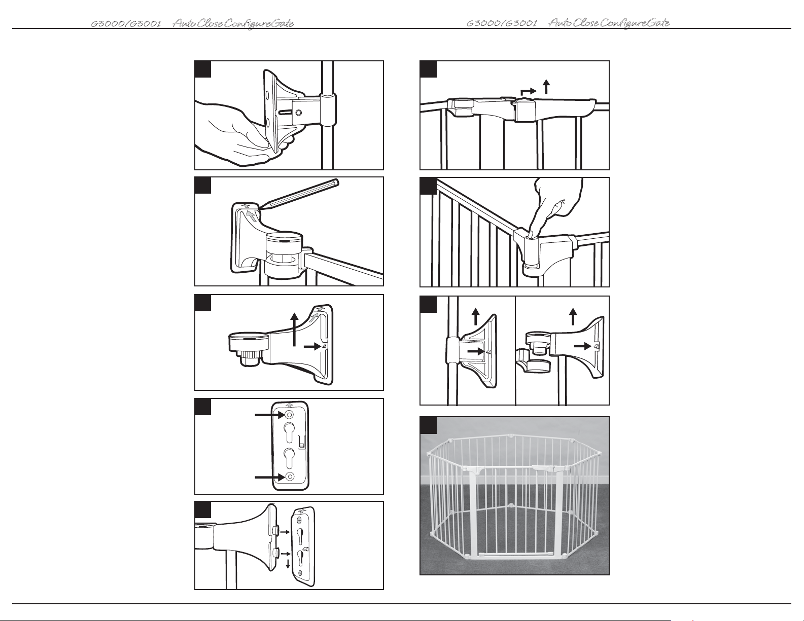
12 Lift locking caps and rotate upper and
lower wall brackets until flush against
mounting surface and lower bar housing is
aligned with the upper bracket assembly.
NOTE: Sliding wall bracket assembly is
adjustable for uneven walls and should be
installed as low as possible.
13 With a pencil, lightly outline brackets on
mounting surface.
14 Remove wall plates from brackets by
pressing locking tabs and sliding up.
15 Hold one wall plate with arrow facing up
inside pencil outline and install using two
wood screws. Repeat for all other wall
plates. NOTE: Screws provided are for
mounting directly into wood. If mounting into
brick, drywall or other surfaces, use
appropriate hardware.
16 Attach gate to wall plates by aligning
arrows and inserting round tabs into wall
plates (a). Slide down to lock (b). Tighten bolts
on sliding wall brackets. Gate should now be
properly installed.
12
13
14
15
16
(a)
(b)
17
10
18
19
20
(b)
(a)
(a) (b)
Uso
17 Deslice hacia atrás el botón de bloqueo
y levante la puerta para abrirla hacia
cualquier dirección. La puerta se cerrará
automáticamente y el pestillo se reactivará
cuando se escucha un “clic”. NOTA: La
sección de la puerta se debe colocar sobre
una superficie nivelada para que el cierre
automático funcione apropiadamente; de otra
manera, será necesario cerrar manualmente
la puerta. Pruebe la característica de cierre
automático antes de usar la reja.
18 Botón para mantener la reja abierta: Este
botón se encuentra en el centro de la parte
superior de la bisagra. Al presionarlo
mientras la puerta se encuentra en posición
totalmente abierta, la puerta se mantendrá
abierta hasta que se presione para cerrarla.
Para quitar la reja
19 Para quitar la reja, presione la ceja de
bloqueo que se encuentra en el conjunto
inferior del soporte de montaje en la pared,
deslícela hacia arriba y sepárela de la placa
de pared. Repita el procedimiento con el
conjunto superior del soporte de montaje en
la pared y separe toda la reja de la pared.
Repita el procedimiento en el otro lado.
Instalación de un área
de juego cerrada
20 Para formar un área de juego cerrada
independiente con la reja ConfigureGate, será
necesario comprar secciones adicionales.
Después de montar todas las secciones
conecte entre sí los dos extremos. Una vez
montadas todas las secciones, ajústelas
hasta lograr la forma deseada.
6
19
 Loading...