

Kidco G22a User Manual

User Guide
Angle MountTMSafeway®Gate Model G22a
for openings 28” - 421/2”
Optional 10” extension Model G22-10 for openings 42” - 63” wide
Rallonge facultative de 25 cm Modèle G22-10 pour les embrasures de 107 à 160 cm
Extensión opcional de 10” modelo G22-10 para aberturas de 42” a 63” de ancho
Only two extension kits recommended per gate
Barrière Angle MountTMSafeway®Modèle G22a
pour les embrasures de 71 à 108 cm
Maximum de deux rallonges recommandées par barrière
TM
Reja Angle-Mount
para aberturas de 28
Se recomiendan sólo dos juegos de extensión por reja
Safeway®Modelo G22a
” - 42
1
2
/
”
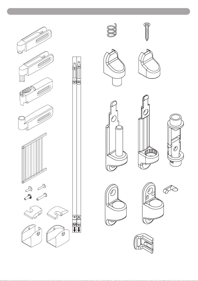
Parts Check List / Liste des Pièces / Verificación de piezas
ux1
u x 1
hx1
h x 1
ab
ix1
i x 1
kx1
k x 1
ab
vx1
v x 1
ox8
o x 8
q x 1
qx2
jx1
j x 1
cx2
c x 2
gx4
g x 4
ex4
dx4
mx4
m x 4
e1 x 2
d1 x 2
lx4
l x 4
fx4
f x 4
e2 x 2
d2 x 2
n x 1
nx1
px1
p x 1
w x 1
r x 1
rx1
y x 1
sx1
s x 1
tx1
t x 1
2

Important Notes
!
ENG
FOLLOW THESE
INSTRUCTIONS
CAREFULLY AND
KEEP THEM FOR
FUTURE REFERENCE
WARNING
• Intended for use with children from 6 months
through 24 months.
• Check the stability of the gate and tighten all
hardware and mountings regularly.
• To prevent serious injury or death, securely
install gate or enclosure and use according to
manufacturer’s instructions.
• Never use with a child able to climb over or
dislodge/open the gate or enclosure.
• Do not use if any part of gate is broken or
missing.
3
• Never use if gate is less than
height.
• Discontinue use if any part of gate is damaged.
/4of child’s
• When installed as instructed, between two
clean structurally sound surfaces, this gate
conforms to:
ASTM F-1004-04 United States Standards
EN 1930:2000 European Standards
This gate is designed for children from 6
months to 24 months. Since each child’s skills
develop at different ages, these age parameters should be monitored against your child’s
own development.
• This product will not necessarily prevent all
accidents. Never leave child unattended.
• Use only spare parts available from KidCo.
• Never allow child to climb or swing on gate.
• Use only with the locking/latching mechanism
securely engaged.
• Closely supervise child when gate is installed
at the top of stairs.
• Never climb over the gate.
• Never hang or tie toys etc. to any part of the
gate.
Maintenance
• No part of the gate requires lubrication.
• Clean using warm soapy water, or a damp
cloth.
• Do not use abrasive cleaners or bleach.
3

Gate Installation
1. Important-Gate must be installed in a
structurally sound opening. The gate must be
mounted to a rigid surface. Ensure mounting
surface (wall, door frame, stairposts, etc.) is
strong, rigid and has an even surface.
2. If using gate on a stairway, it must be placed
either on top stair or on lowest stair at the
bottom. (Figs. 1 & 2)
3. When assembling the gate, it is important
that the sections fit without any distance
between rails or bars. (Fig 3).
FINDING APPROPRIATE WIDTH OF GATE
4.
With the two sections aligned against each
other, place gate against one side of opening
where it is to be installed. The distance between
the opposite side of gate and wall/doorframe
must be between 2” – 4
5. Once proper gate width is achieved, place
assembly parts (d1) and (e1) on top gate rail, and
place assembly parts (d2) and (e2) on bottom rail.
Insert screws (f) and screw sockets (g) into all four
assembly fittings according to (Fig 4).
6. Place handle and hinge parts (h), (i), (j) and (k)
onto the gate.
Insert the screws (l) and the screw sockets (m)
into all four parts according to picture. Do not
fully tighten yet. (Fig. 5)
7. HINGE SIDE MOUNTING
Screws provided are for mounting directly
into wood. If mounting into brick, drywall or
other surfaces, use appropriate hardware. If
installing into hardwood (i.e. oak), drilling a
pilot hole may be necessary.
Cut out templates along all dotted lines,
separating template (a) from (b).
Hold template (a) vertically and completely outstreched against mounting surface with the end
marked " " even with the floor. Mark screw hole
positions. Remove the template. (Fig. 6)
8. Using 2 wood screws (o) mount upper hinge
bracket (n) with the hole and the post pointing
up, in top 2 screw hole positions. Using 2 wood
screws (o) mount lower hinge bracket (p) with
angled side facing down, in bottom 2 screw
hole positions. (Fig. 7)
3
/4”. (Fig.3)
9. LOCKING SIDE MOUNTING
Screws provided are for mounting directly
into wood. If mounting into brick, drywall or
other surfaces, use appropriate hardware. If
installing into hardwood (i.e. oak), drilling a
pilot hole may be necessary.
Hold template (b) vertically and completely outstreched against mounting surface with the end
marked " " even with the floor. Mark screw hole
positions. Remove the template. (Fig. 8)
10. Determine which direction the gate should
open. For the top of stairways, gate should
never open out over the stairs. Insert stop pin
(t) into holes of lower locking bracket (s). Insert
stop clip (y) into upper latch (r). (Fig. 9) The
longer portion of the stop pin and the outer
edge of the stop clip should both be on the
same side. Important – The gate cannot open
to the stop pin/stop clip side. Using 2 wood
screws (o) mount lower locking bracket (s) with
hole facing up, in bottom 2 screw hole
positions. Using 2 wood screws (o) install upper
locking bracket (w). Place part (r) onto upper
locking bracket (w). (Fig. 10).
11. Place gate onto hinge parts. Next, place
spring (u) and hinge cap (v) onto upper hinge
bracket post. (Fig 11)
12. IMPORTANT: ENSURE HINGE CAP CANNOT BE PUSHED UP AND IS LOCKED IN
PLACE (Fig. 12)
Center gate in the opening. Loosen screws on
parts (h), (i), (j), and (k) and adjust so they rest
securely into hinge and locking side brackets.
The distance between gate and wall/doorframe
must be between 1” – 2
If gate is installed on an angle, part (r) will need
to be rotated so that the gate handle rests
securely inside upper locking bracket. (Fig.14)
Once the gate handle rests securely inside
locking bracket, slide locking cap (q) onto upper
locking bracket (w).
IMPORTANT: ENSURE LOCKING CAP
CANNOT BE PUSHED UP AND IS LOCKED IN
PLACE.
Be certain to tighten all gate screws (h), (i), (j)
and (k).
3
/8”. (Fig 13)
4

Operation
13. To open gate, pull top locking latch back-
wards with your thumb and lift gate up and out
of hinge. (Fig. 15).
Window Barrier Installation
Gate must be installed in one of two ways:
either inside window casing (Fig. 16) or directly
onto face of window casing (Fig. 17).
Follow ’gate’ installation instructions through #6.
After cutting out templates (a) and (b), hold template (a) vertically and completely outstreched
against mounting surface with the end marked
" " even with bottom of window or resting on
window sill. Do this for both templates and continue following ’gate’ installation instructions until
#12.
If mounting directly to face of window casing,
stop pin (t) will not be needed. If mounting inside
window casing, continue following ’gate’ instructions exactly from #12 through completion.
IIMMPPOORRTTAANNTT
If gate is outside mounted to a wall or window
(instead of a doorframe), it is very important that
the wall hardware is flush with the edge.
When the gate is in place make sure that:
(Fig. 18)
a) The distance between the wall/door frame
and the 1st bar is between 1” – 2
sides.
b) The distance between the floor and the
lowest part of the gate frame is between
3
/4” – 21/2”.
3
/8” on both
14. When closing gate, be sure that both upper
and lower locking side parts are resting securely
in brackets and the upper latch is locked.
c) The spring is placed on top of hinge part on
gate. It must not be underneath.
d) The stop pin is placed so that the gate can
not open out over the stairs - if any.
e) The catch on the handle can move freely
(back and forth) and that it fits properly into the
slot on the upper locking bracket.
f) All screws are tightened.
NOTE. GATE SHOULD ALWAYS BE IN THE
LOCKED POSITION. IF GATE IS OPEN AND
EXCESSIVE PRESSURE IS APPLIED, (SUCH
AS STANDING OR SWINGING ON THE GATE)
STRUCTURAL DAMAGE MAY OCCUR.
15. Temporary Removal
The gate may be removed by pressing back on
the locking tab on top of upper hinge while sliding the hinge cap up. Remove spring and lift
gate off top and bottom hinges. FOR SAFETY
REASONS, RETURN SPRING AND HINGE
CAP ONTO HINGE POST, MAKE SURE CAP
IS LOCKED IN PLACE.
5

Warranty
KIDCO LIMITED WARRANTY
Your KidCo product is warranted to be free from manufacturing defects for a period of one
year from date of purchase under normal non commercial use and in compliance with the
operating instructions. This warranty extends only to the original retail purchaser and is only
valid when supplied with proof of purchase.
KidCo will either repair, or at our option replace, free of charge, any parts necessary to
correct defects in material or workmanship during the warranty period. This warranty is
complete and exclusive. The warranty expressly disclaims liability for incidental, special and
consequential damages of any nature. Any implied warranty arising by operation of law
shall be limited in operation to the terms of this warranty. Some states do not allow the
exclusion or limitation of incidental or consequential damages or limitations on how long an
implied warranty lasts, so the above may not apply to you. This warranty gives you specific
legal rights, and you may have other rights which vary from state to state.
SHOULD REPAIR OR PARTS BE NECESSARY
Should a repair be needed during the warranty period, ship the gate in the original carton or
similar protective container (check any retail store or purchase from UPS) and send freight
prepaid (we suggest UPS) to:
KidCo, Inc., 1013 Technology Way, Libertyville, IL 60048-5349.
Include a note with your return address, day-time telephone number, and specify what is
wrong with the product. Repairs can normally be made within 48 hours after receipt at
KidCo. For additional information CALL our customer service department at (800) 553-5529.
6
 Loading...