

Page 1

User Guid e
Patents
Pending
SAFEWAY® Gate Model G20d-C
for openings 243/4” to 431/2” wide
pour ouvertures de 63 à 110 cm de largeur
para aberturas de 243/4” a 431/2” de ancho
Optional 24” extension Model G24 for openings 431/2” to 66” wide
Rallonge de 62,9 cm en option modèle G24 pour ouvertures de 110 à 167,5 cm de largeur
Extensión opcional de 24”, Modelo G24, para aberturas de 431/2” a 66” de ancho
Only one extension recommended per gate
Une seule rallonge recommandée par barrière
Se recomienda sólo una extensión por reja
Page 2
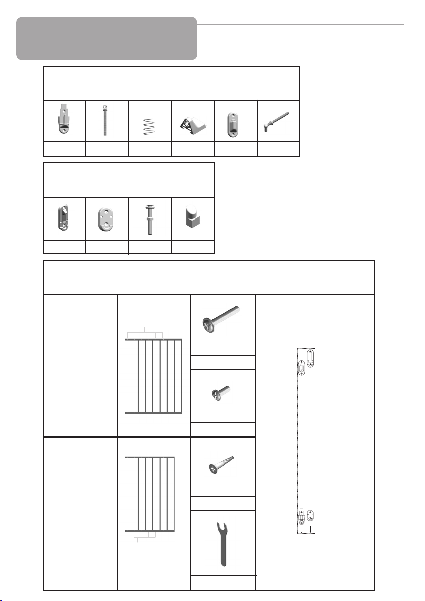
Parts Check List
Liste de contrôle des pièces
Lista de verificación de piezas
Hinge Side Hardware
Quincaillerie côté charnières
Herraje del lado de la bisagra
(c) - 1 (d) - 1 (e) - 1 (f) - 1 (g) - 1 (h) - 1
Locking Side Hardware
Quincaillerie côté verrouillage
Herraje del lado del mecanismo de cierre
(l) - 1 (m) - 1 (n) - 2 (o) - 2
General Hardware
Quincaillerie générale
Herraje general
Adjustment holes
Trous de réglage
Orificios de ajuste
1 Gate section
with 7 bars
1 Section de
barrière à 7
barres
1 Sección de la
reja con 7
barras
(i) - 4
(j) - 4
1 Gate section
with 6 bars
1 Section de
barrière à 6
barres
1 Sección de la
reja con 6
barras
Adjustment holes
Trous de réglage
Orificios de ajuste
2
(k) - 8
(p) - 1
1 Hinge side template (a)
1 Pochoir côté charnières (a)
1 Plantilla para el lado de la
bisagra (a)
b
a
1 Locking side template (b)
1 Pochoir côté verrouillage (b)
1 Plantilla para el lado del
mechanismo de cierre (b)
Page 3

INDEX
ENG
FRE
SPA
User Guide
Parts Check List . . . . . . . . . . . . . . . . . . . . . . . . . . . . . . . 2
Safeway® Gate Model G20d . . . . . . . . . . . . . . . . . . . . . 4-6
Warranty. . . . . . . . . . . . . . . . . . . . . . . . . . . . . . . . . . . . . 6
Parts Price List . . . . . . . . . . . . . . . . . . . . . . . . . . . . . . . . 15
Method of Payment . . . . . . . . . . . . . . . . . . . . . . . . . . . . 16
Illustrations . . . . . . . . . . . . . . . . . . . . . . . . . . . . . . . . . . . 19-21
Guide d’utilisation
Liste de Contrôle des Pièces. . . . . . . . . . . . . . . . . . . . . 2
Barrière Safeway® Modèle G20d. . . . . . . . . . . . . . . . . . 7-9
Garantie . . . . . . . . . . . . . . . . . . . . . . . . . . . . . . . . . . . . . 10
Liste des prix des piéces. . . . . . . . . . . . . . . . . . . . . . . . 15
Mode de Paiement . . . . . . . . . . . . . . . . . . . . . . . . . . . . . 17
Figures . . . . . . . . . . . . . . . . . . . . . . . . . . . . . . . . . . . . . . 19-21
Guía del usuario
Lista de Verificación de Piezas . . . . . . . . . . . . . . . . . . . 3
Reja Safeway® Modelo G20d . . . . . . . . . . . . . . . . . . . . 11-13
Garantía . . . . . . . . . . . . . . . . . . . . . . . . . . . . . . . . . . . . . 14
Lista de precious de las piezas . . . . . . . . . . . . . . . . . . . 15
Metodo de Pago. . . . . . . . . . . . . . . . . . . . . . . . . . . . . . . 18
Ilustraciones . . . . . . . . . . . . . . . . . . . . . . . . . . . . . . . . . . 19-21
3
Page 4

Important Information
ENG
IMPORTANT KEEP FOR FUTURE REFERENCE
• Please take a few minutes to read the instructions thoroughly. Failure to do so may result in
damage to the gate or in worst case injury to
your child.
• When unpacking the gate, carefully check all
parts. Do not use this gate if parts are broken or
missing.
WARNING
• Intended for use with children
from 6 months through 24
months.
• Check the stability of the gate
and tighten all hardware and
mountings regularly.
• To prevent serious injury or death,
securely install gate or enclosure
and use according to manufac-
turer’s instructions.
• Never use with a child able to
climb over or dislodge/open the
gate or enclosure.
• Do not use if any part of gate is
broken or missing.
• Never use if gate is less than 3/4
of child’s height.
• When installed as instructed, between two clean
structurally sound surfaces, this gate conforms to:
ASTM F-1004-09 United States Standards
EN 1930:2000 European Standard
This gate is designed for children from 6 months
to 24 months. Since each child’s skills develop at
different ages, these age parameters should be
monitored against your child’s own development.
• Discontinue use if any part of gate
is damaged.
• This product will not necessaily
prevent all accidents. Never leave
child unattended.
• Use only spare parts available
from KidCo.
• Never allow child to climb or
swing on gate.
• Use only with the locking/latching
mechanism securely engaged.
• Closely supervise child when gate
is installed at the top of stairs.
• Never climb over the gate.
• Never hang or tie toys etc. to any
part of the gate.
Maintenance
• No part of this gate requires lubrication.
• Clean using warm soapy water, or a damp
cloth.
4
• Do not use abrasive cleaners or bleach.
• If using outdoors, and to help prevent rust,
treat metal parts with a rust inhibitor.
Some rusting may still occur.
Page 5

Installation
For further clarification, please see back of
user guide for corresponding drawings.
1. IMPORTANT
Gate must be installed in a structurally sound
opening. The hinge side of gate must be
mounted to a rigid surface.
Ensure mounting surface (wall, door frame,
stairpost, etc.) is strong, rigid and has an
even surface.
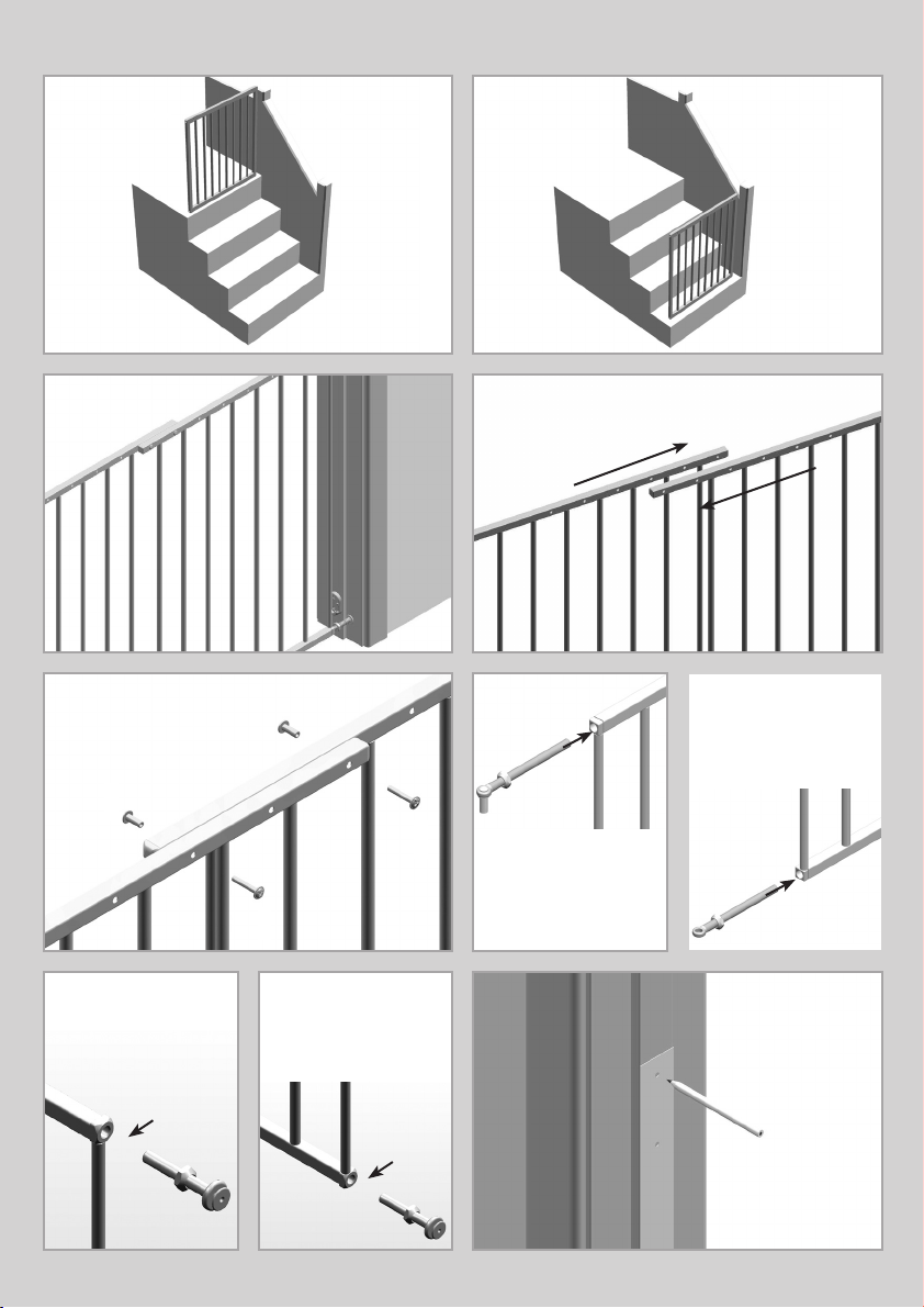
2. If using gate on a stairway, it must be placed
either on top stair or on lowest stair at the
bottom.
3. The correct width will be achieved by
adjusting gate sections and all four corner
spindles. Each spindle adjusts individually and
may be extended varying lengths to allow for
molding, uneven walls, etc. Spindles may be
extended a minimum of 11/4” (hinge side) or 1”
(on locking side) and a maximum of 3”.
4. Adjust sections until gate is approximately
the correct width and adjustment holes are
aligned and overlap in two places on both the
top and bottom rail (maximum overlap is 5
bars).
Sections should fit without any distance
between rails or bars.
5. Place screws (i) and screw sockets (j) in top
and bottom sets of overlapping adjustment
holes nearest hinge and locking sides of gate.
Do not fully tighten yet.
6. Screw upper hinge spindle (h) into top rail of
one gate section.
Screw lower hinge spindle (d) into bottom rail of
same side.
Extend spindles equally.
7. Screw locking latch spindles (n) into top and
bottom rails of second gate section.
Extend spindles equally.
Final spindle adjustments will be made later.
8. Hinge Side Mounting
Screws provided are for mounting directly
into wood. If mounting into brick, drywall or
other surfaces, use appropriate hardware. If
installing into hardwood, (i.e. oak), drilling a
pilot hole may be necessary.
Cut out templates along all dotted lines,
separating template (a) from (b).
Hold template (a) vertically and completely outstretched against mounting surface with the end
marked “ ” even with the floor.
➤
Mark 4 screw hole positions.
Remove template.
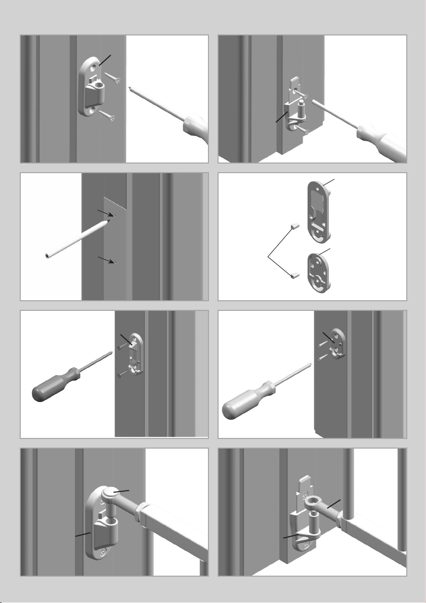
9. Using 2 wood screws (k), mount upper hinge
(g) (with hole pointing up) in top 2 screw hole
positions.
10. Using 2 wood screws, (k) mount lower hinge
bottom (c) (with post pointing up) in bottom 2
screw hole positions.
11. Locking Side Mounting
Screws provided are for mounting directly
into wood. If mounting into brick, drywall or
other surfaces, use appropriate hardware. If
installing into hardwood, (i.e. oak), drilling a
pilot hole may be necessary.
Hold template (b) vertically and completely outstretched against mounting surface with the end
marked “ ” even with the floor.
Mark 4 screw hole positions.
Remove template.
➤
12. Determine which direction the gate should
open. For the top of stairways, gate should
never open out over the stairs.
Insert stop pins (o) from behind in holes of
locking latch bracket (l) and lower latch bracket
(m) opposite desired opening direction.
Important: The gate cannot open to the stop
pin side.
13. Using 2 wood screws (k) mount locking latch
bracket (l) in top 2 screw hole positions.
14. Using 2 wood screws (k), mount lower latch
bracket (m) in bottom 2 screw hole positions.
15. Center gate in opening. Adjust upper hinge
spindle (h) so post fits into upper hinge hole (g).
16. Adjust lower hinge spindle (d) so end fits
over lower hinge post (c).
Space between end of gate and mounting
surface on hinge side may be no less than
11/4” and not more than 3”.
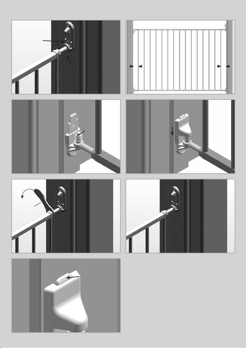
17. Adjust locking latch spindles (n) until they fit
securely into both latch brackets. Top spindle
must click under locking latch when in the
closed position. Space between end of gate and
mounting surface on locking side may be no
less than 1” and not more than 3”.
18. If adjusting the spindles does not achieve
the correct length, it may be necessary to lift
gate off hinges and readjust the sections (see
step 3). Check that gate can be smoothly
opened and closed.
5
Page 6

Installation
19. Place spring (e) on lower hinge post.
20. Place lower hinge cap (f) on lower hinge and
push down until it clicks into locked position.
IMPORTANT. ENSURE HINGE CAP
CANNOT BE PUSHED UP AND IS LOCKED IN
PLACE.
21. Using Phillips head screwdriver, tighten all
screws and screw sockets.
With wrench (p), securely tighten all 4 lock nuts
toward the gate.
22. Operation
To open gate, press down on locking latch with
thumb and lift gate out of upper and lower
brackets.
To lock gate, top locking latch spindle must
click under locking latch and bottom latch
spindle must rest in bottom bracket as shown in
figure 17.
NOTE. GATE SHOULD ALWAYS BE IN THE
LOCKED POSITION. IF GATE IS OPEN AND
EXCESSIVE PRESSURE IS APPLIED, (SUCH
AS STANDING OR SWINGING ON THE GATE)
STRUCTURAL DAMAGE MAY OCCUR.
23. Temporary Removal
The gate may be removed by pressing back on
the locking tab on top of lower hinge bottom
while sliding the hinge cap up. Remove spring
and lift gate off top and bottom hinges.
FOR SAFETY REASONS, RETURN SPRING
AND HINGE CAP ONTO HINGE POST,
MAKING SURE CAP IS LOCKED IN PLACE.
Warranty
KIDCO LIMITED WARRANTY
Your KidCo product is warranted to be free from manufacturing defects for a period of one year
from date of purchase under normal non commercial use and in compliance with the operating
instructions. This warranty extends only to the original retail purchaser and is only valid when
supplied with proof of purchase.
KidCo will either repair, or at our option replace, free of charge, any parts necessary to
correct defects in material or workmanship during the warranty period. This warranty is
complete and exclusive. The warranty expressly disclaims liability for incidental, special and
consequential damages of any nature. Any implied warranty arising by operation of law
shall be limited in operation to the terms of this warranty. Some states do not allow the
exclusion or limitation of incidental or consequential damages or limitations on how long an
implied warranty lasts, so the above may not apply to you. This warranty gives you specific
legal rights, and you may have other rights which vary from state to state.
SHOULD REPAIR OR PARTS BE NECESSARY
Should a repair be needed during the warranty period, ship the gate in the original carton or
similar protective container (check any retail store or purchase from UPS) and send freight
prepaid (we suggest UPS) to:
KidCo Inc., 1013 Technology Way, Libertyville, IL 60048-5349.
Include a note with your return address, day-time telephone number, and specify what is
wrong with the product. Repairs can normally be made within 48 hours after receipt at KidCo.
For additional information CALL our customer service department at (800) 553-5529.
6
Page 7

Remarques importantes
FRE
LIRE ATTENTIVEMENT CES
INSTRUCTIONS ET
LES CONSERVER
POUR POUVOIR
S’Y RÉFÉRER
ULTÉRIEUREMENT.
ATTENTION
• Utilisation prévue: enfants âgés de
6 à 24 mois.
• Vérifier la stabilité de la barrière et
resserrer régulièrement toute la
quincaillerie et les supports.
• Pour écarter tout risque de bles-
sure grave, voire mortelle, installer
solidement la barrière ou la fer-
meture et utiliser conformément
aux instructions du fabricant.
• Ne jamais utiliser pour un enfant
capable de grimper par-dessus la
barrière ou la fermeture ou de la
retirer.
• Ne pas utiliser si une pièce de la
barrière est cassée ou manquante.
• Ne jamais utiliser si la barrière ne
mesure pas au moins les trois
quarts de la taille de l’enfant.
• Cesser l’utilisation si un com-
posant quel conque de la barrière
est endommagé.
Cette barrière de sécurité a été conçue pour les
enfants âgés de 6 à 24 mois. Comme les
capacités de chaque enfant se développent à
des âges différents, le facteur « âge » doit être
ajusté en fonction du propre développement de
l’enfant.
La barrière standard s’adapte à des ouverture de
62,9 à 110,5 cm de largeur.
La barrière à extension en option s’adapte à des
ouverture de 110,5 à 167,5 cm de largeur.
Quand elle est installée conformément au mode
d'emploi, entre deux surfaces solides et stables,
cette barrière est conforme aux normes:
ASTM F-1004-09 United States Standards
EN 1930:2000 Normes européennes
• Ce produit n’empêchera pas
nécessairement tous les acci-
dents. Ne jamais laisser un enfant
sans surveillance.
• Utiliser uniquement des pièces
détachées KidCo.
• Ne jamais laisser un enfant
grimper sur la barrière ni la
secouer.
• Utiliser uniquement avec le
mécanisme de verrouillage/
blocage solidement enclenché.
• Surveiller de près l’enfant si la
barrière est installée en haut d’un
escalier.
• Ne jamais grimper sur la barrière.
• Ne jamais suspendre ni attacher
de jouets, etc. sur une partie
quelconque de la barrière.
7
Page 8

Entretien
• Aucune partie de la barrière n’exige de
lubrification.
• Nettoyer à l’aide d’une éponge avec de
l’eau chaude et un détergent doux.
Installation
• Ne pas utiliser de nettoyants abrasifs ou un
agent blanchissant.
• Dans le cas d´une utilisation extérieure et
pour empêcher la formation de rouille,
traiter les pièces métalliques avec un
antirouille.
L´apparition de rouille est toujours possible.
Pour plus de précisions, voir les dessins correspondants au dos de ce guide d'utilisation.
1. IMPORTANT.
La barrière doit être installée dans une
ouverture dont la structure est solide. Le
côté charnières doit être fixé sur une surface
rigide.
S’assurer que la surface de fixation (mur, embrasure de porte, montants d’escaliers, etc.) est
solide, rigide et plane.
2. Si la barrière est utilisée dans un escalier, elle
devra être placée en haut de l’escalier ou en
bas, sur la première marche.
3. La largeur correcte sera obtenue en ajustant
les sections de barrière et les quatre axes de
coin. Chaque axe se règle individuellement et
peut être allongé à des longueurs diverses pour
s’adapter aux moulures, murs irréguliers, etc.
Les axes peuvent être allongés de 6 mm
minimum (côté charnières) ou 2,5 cm (côté
verrouillage), mais pas au-delà de 7,5 cm.
4. Ajustez les sections jusqu’à ce que la bar-
rière soit approximativement à la largeur cor-
recte et que les trous de réglage soient alignés
et se chevauchent en deux endroits sur les rails
inférieur et supérieur (chevauchement maximal:
5 barres).
Les sections doivent s’ajuster sans espace entre
les rails ou les barres.
5. Placer les vis (i) et les cuvettes à vis (j) dans
les jeux supérieurs et inférieurs des trous de
réglage superposés les plus proches des côtés
charnières et verrouillage de la barrière.
Pour l’instant, ne pas serrer à fond.
6. Visser l’axe de charnière supérieure (h) dans
le rail supérieur d’une section de barrière.
Visser l’axe de charnière inférieure (d) dans le rail
inférieur du même côté.
Allonger les axes uniformément.
7. Visser les axes des loquets (n) dans les rails
supérieur et inférieur de la seconde section de
barrière. Allonger les axes uniformément.
Les derniers réglages des axes auront lieu
ultérieurement.
8. Fixation côté charnières
Les vis fournies permettent une fixation
directe sur bois. S’il s’agit d’une fixation sur
de la brique, une cloison sèche ou d’autres
surfaces, utiliser la quincaillerie appropriée.
En cas d’installation sur bois dur (chêne, par
ex.), percer au besoin un avant-trou.
Découper les gabarits le long de tous les
pointillés pour séparer le gabarit (a) du (b).
Maintenir le pochoir (a) à la verticale et
complètement tendu contre la surface de
fixation en plaçant l’extrémité portant la flèche
“ ” au niveau du sol.
Marquer les quatre positions des trous de vis.
Retirer le pochoir.
9. En utilisant les deux vis à bois (k), fixer la
charnière supérieure (g) (le trou pointant vers le
haut) dans les deux positions de trous
supérieurs.
10. En utilisant les deux vis à bois (k), fixer la
partie inférieure de la charnière inférieure (c)
(le trou pointant vers le haut) dans les deux
positions de trous inférieurs.
11. Fixation côté verrouillage
Les vis fournies permettent une fixation
directe sur bois. S’il s’agit d’une fixation sur
de la brique, une cloison sèche ou d’autres
surfaces, utiliser la quincaillerie appropriée.
En cas d’installation sur bois dur (chêne, par
ex.), percer au besoin un avant-trou.
Maintenir le pochoir (b) à la verticale et
complètement tendu contre la surface de
fixation en plaçant l’extrémité portant la flèche
➤➤
“ ” au niveau du sol.
Marquer les quatre positions des trous de vis.
Retirer le pochoir.
8
Page 9

Installation
12. Déterminer la direction d’ouverture de la
barrière. Pour une installation en haut d’un
escalier, la barrière ne doit jamais s’ouvrir
vers l’escalier.
Insérer les goupilles d’arrêt (o) par derrière dans
les trous du support de loquet (l) et du support
de loquet inférieur (m), à l’opposé de la direction
d’ouverture souhaitée.
Important: La barrière ne peut pas s’ouvrir côté
goupilles d’arrêt.
13. En utilisant les deux vis à bois (k), fixer le
support du loquet (l) dans les deux positions de
trous de vis.
14. En utilisant les deux vis à bois (k), fixer le
support du loquet inférieur (m) dans les deux
positions de trous de vis inférieurs.
15. Centrer la barrière dans l’ouverture. Ajuster
l’axe de la charnière supérieure (h) pour que le
montant s’insère dans le trou de la charnière
supérieure (g).
16. Ajuster l’axe de charnière inférieure (d) pour
insérer son extrémité dans le montant de
charnière inférieure (c).
L’espace entre l’extrémité de la barrière et la
surface de fixation côté charnières ne peut pas
être inférieur à 3,1 cm et supérieur à 7,5 cm.
17. Ajuster les axes de loquets (n) jusqu’à ce
qu’ils s’insèrent dans les deux supports. Un
déclic de l’axe supérieur sous le loquet indique
la position fermée.
L’espace entre l’extrémité de la barrière et la
surface de fixation côté verrouillage ne peut pas
être inférieur à 2,5 cm et supérieur à 7,5 cm.
18. Si le réglage des axes ne suffit pas à obtenir
la longueur correcte, il sera peut-être nécessaire
de soulever la barrière des charnières et de
rajuster les sections (voir étape 3).
S’assurer que la barrière s’ouvre et se ferme sans
à-coups.
19. Placer le ressort (e) sur le montant de
charnière inférieure.
20. Placer le capuchon de charnière inférieure (f)
sur la charnière inférieure et pousser jusqu’à ce
qu’il s’enclenche en position verrouillée.
IMPORTANT. S’ASSURER QUE LE CAPUCHON
DE CHARNIÈRE NE PEUT PAS ÊTRE
REMONTÉ ET QU’IL EST BLOQUÉ EN
POSITION.
21. À l’aide d’un tournevis cruciforme, serrer
toutes les vis et cuvettes à vis.
Avec la clé (p), bien serrer les quatre contre-
écrous vers la barrière.
22. Mode d’emploi
Pour ouvrir la barrière, appuyer sur le loquet avec
le pouce et soulever la barrière des
supports supérieur et inférieur.
Pour verrouiller la barrière, l’axe du loquet
supérieur doit s’enclencher sous le loquet avec
un déclic et l’axe du loquet inférieur devra être en
appui dans le support inférieur, comme
illustré à la figure 17.
REMARQUE. LA BARRIÈRE DOIT TOUJOURS
ÊTRE EN POSITION VERROUILLÉE. SI LA
BARRIÈRE EST OUVERTE ET QU’UNE
PRESSION EXCESSIVE LUI EST APPLIQUÉE
(ENFANT MONTÉ OU SE BASCULANT SUR
LA BARRIÈRE NOTAMMENT), DES DÉGTS
STRUCTURELS SONT À CRAINDRE.
23. Retrait temporaire
La barrière peut être retirée en rétractant la patte
de blocage sur le dessus de la partie inférieure
de la charnière inférieure tout en remontant le
capuchon de charnière vers le haut. Retirer le
ressort et soulever la barrière en la dégageant
des charnières supérieure et inférieure.
POUR DES RAISONS DE SÉCURITÉ,
REMETTRE LE RESSORT ET LE CAPUCHON
DE CHARNIÈRE SUR LE MONTANT DE
CHARNIÈRE ET S’ASSURER QUE LE
CAPUCHON EST BIEN EN PLACE.
9
Page 10

Garantie
GARANTIE LIMITÉE KIDCO
Votre produit KidCo est garantit contre tout défaut de fabrication pendant une période d’un
an à partir de la date d’achat dans des conditions normales d’utilisation non commerciale
et conforme au mode d’emploi. Cette garantie est uniquement accordée à l’acheteur
d’origine chez un revendeur et elle est uniquement valable pour toute réclamation
accompagnée d’un justificatif d’achat.
KidCo réparera ou, à sa discrétion, remplacera gratuitement toute pièce nécessaire pour
corriger les vices de matériel ou de fabrication durant la période de garantie. Cette garantie
est complète et exclusive. Par cette garantie, KidCo rejette expressément toute
responsabilité vis-à-vis de dommages accessoires, spéciaux et indirects, quelle qu’en soit
la nature. Toute garantie tacite par effet de la loi se limitera aux termes de cette garantie.
Certaines provinces n’autorisant pas l’exclusion ou la limitation de dommages
accessoires ou indirects en rapport avec la durée d’une garantie tacite, il est possible que
ce qui précède ne vous concerne pas. Cette garantie vous accorde des droits légaux
spécifiques et il est possible que vous ayez d’autres droits, variables d’une province à
l’autre.
POUR TOUTE RÉPARATION OU PIÈCE NÉCESSAIRE
Si une réparation s’avère nécessaire durant la période de garantie, expédiez la barrière de
sécurité dans son carton d’origine ou une boîte de protection similaire (disponible auprès
d’un revendeur ou vendue par UPS) et envoyez en fret payé d’avance (UPS suggéré) à:
KidCo Inc., 1013 Technology Way, Libertyville, IL 60048-5349.
Incluez une note mentionnant vos adresse de retour et numéro de téléphone, et décrivez
la nature du problème. Les réparations sont normalement effectuées sous 48 heures après
réception par KidCo. Pour plus d’informations, REJOIGNEZ notre service clientèle au
(800) 553-5529.
10
Page 11

Notas importantes
SPA
SIGA CUIDADOSAMENTE ESTAS
INSTRUCCIONES
Y CONSÉRVELAS
PARA SU REFERENCIA FUTURA
ADVERTENCIA
• Diseñada para usarse con niños
de 6 a 24 meses de edad.
• Revise la estabilidad de la reja y
apriete regularmente todo el her-
raje y los accesorios de montaje.
• Para evitar una lesión grave o la
muerte, instale la reja o el corral
con seguridad y úselo de acuerdo
con las instrucciones del fabri-
cante.
• Nunca use estos productos para
un niño que se pueda subir a
ellos o abrir la reja o el corral.
• No use la reja si alguna de sus
partes falta o está rota.
• Nunca use la reja si su altura es
menor que 3/4 partes de la esta-
tura del niño.
La reja está diseñada para niños de 6 a 24
meses de edad. Debido a que cada niño
desarrolla destrezas a diferentes edades, estos
límites de edad se deben ajustar al desarrollo
particular de su hijo.
La reja básica cabe en aberturas de 243/4” a
431/2”.
La reja con extensión opcional cabe en
aberturas de 431/2” a 66”.
Si se monta siguiendo las instrucciones, entre
dos superficies limpias y estructuralmente
sólidas, esta barrera cumple con la norma:
ASTM Normas F-1004-09 de Estados Unidos
EN Normas europeas 1930:2000
• Este producto no necesariamente
evitará todos los accidentes.
Nunca deje desaten dido al niño.
• Use sólo piezas de repuesto de
KidCo.
• Nunca permita que el niño se
suba o se columpie en la reja.
• Use sólo con el mecanismo de
cierre fijamente asegurado.
• Supervise muy de cerca al niño
cuando se instale la reja en la
parte superior de las escaleras.
• Nunca se pase sobre la reja.
• Nunca cuelgue ni amarre juguetes
u otros objetos a ninguna parte
de la reja.
• No use la reja si alguna de sus
partes está dañada.
11
Page 12

Cuidado
• Ninguna pieza de la reja requiere lubricación.
• Límpiela con una esponja y con agua
caliente y un detergente suave.
Instalación
• No use limpiadores abrasivos ni
blanqueador.
• Si se va a usar en el exterior, y para evitar la
oxidación, trate las partes metálicas con un
inhibidor de corrosión.
Aún así puede ocurrir algo de corrosión.
Para aclaración adicional, consulte los
diagramas correspondientes en la parte de
atrás de la guía del usuario.
1. IMPORTANTE.
La reja se debe instalar en una abertura
estructuralmente sólida. El lado de la bisagra
de la reja debe estar montado en una
superficie rígida.
Asegúrese de que la superficie de montaje
(paredes, marco de la puerta, postes de la
escalera, etc.) sea resistente, rígida y esté
uniforme.
2. Si va a usar la reja en una escalera, debe
colocarla ya sea en el escalón superior o en el
último escalón de la parte inferior.
3. La anchura correcta se logrará ajustando las
secciones de la reja y los cuatro pivotes de las
esquinas. Cada pivote se ajusta individualmente
y se puede extender varios tramos para conformarse a molduras, paredes irregulares, etc. Los
pivotes se pueden extender un mínimo de
11/4” del lado de la bisagra o 1” del lado del
mecanismo de cierre, y un máximo de 3”.
4. Ajuste las secciones hasta que la reja esté
aproximadamente a la anchura correcta y los
orificios de ajuste estén alineados y se
traslapen en dos lugares tanto en el barandal
inferior como en el superior (el traslape máximo
es de 5 barras).
Las secciones deben caber sin que haya
distancia entre barandales o barras.
5. Coloque los tornillos (i) y los manguitos
roscados (j) en las series superior e inferior de
los orificios de ajuste traslapados que se
encuentren más cerca de los lados de la
bisagra y del mecanismo de cierre de la reja.
Todavía no los apriete completamente.
6. Atornille el pivote de la bisagra superior (h) en
el barandal superior de una sección de la reja.
Atornille el pivote de la bisagra inferior (d) en el
barandal inferior del mismo lado.
Extienda los pivotes en igual medida.
7. Atornille los pivotes de fijación (n) en los
barandales superior e inferior de la segunda
sección de la reja.
Extienda los pivotes en igual medida.
El ajuste final de los pivotes se hará posteriormente.
8. Montaje del lado de la bisagra
Los tornillos que se proporcionan son para
montarse directamente en la madera. Si el
montaje se va a hacer en ladrillo, muro seco
u otras superficies, use el herraje adecuado.
Si se va a hacer en madera dura (por
ejemplo, roble), es posible que se necesite
hacer un agujero piloto.
Découper les gabarits le long de tous les
pointillés pour séparer le gabarit (a) du (b).
Recorte las plantillas a lo largo de las líneas
punteadas separando la plantilla (a) de la
plantilla (b).
Sujete la plantilla (a) vertical y completamente
extendida contra la superficie de montaje, con el
extremo marcado “ ” al ras del piso.
Marque la posición de los 4 orificios para los
tornillos.
Retire la plantilla.
➤
9. Con dos tornillos para madera (k), monte la
bisagra superior (g) (con el orificio hacia arriba)
en los dos orificios para tornillos superiores.
10. Con dos tornillos para madera (k), monte la
parte de abajo de la bisagra inferior (c) (con el
poste hacia arriba) en los dos orificios para
tornillos inferiores.
11. Montaje en el lado del mecanismo de
cierre
Los tornillos que se proporcionan son para
montarse directamente en la madera. Si el
12
Page 13

Instalación
montaje se va a hacer en ladrillo, muro seco
u otras superficies, use el herraje adecuado.
Si se va a hacer en madera dura (por
ejemplo, roble), es posible que se necesite
hacer un agujero piloto.
Sujete la plantilla (b) vertical y completamente
extendida contra la superficie de montaje, con el
extremo marcado “ ” al ras del piso.
Marque la posición de los 4 orificios para los
tornillos.
Retire la plantilla.
➤
12. Determine la dirección hacia la cual se va
a abrir la reja. Cuando se instale en la parte
superior de las escaleras, la reja nunca se
debe abrir sobre las escaleras.
Introduzca los pivotes de tope (o) desde la parte
posterior de los orificios del soporte del
mecanismo de cierre (l) y el soporte de fijación
inferior (m) que se encuentran en posición
opuesta a la dirección hacia donde desea que
se abra la reja.
Importante: La reja no se puede abrir hacia el
lado del pivote de tope.
13. Con dos tornillos para madera (k) monte el
soporte del mecanismo de cierre (l) en los dos
orificios para tornillos superiores.
14. Con dos tornillos para madera (k) monte el
soporte de fijación inferior (m) en los dos
orificios para tornillos inferiores.
15. Centre la reja en la abertura. Ajuste el
pivote de la bisagra superior (h) de manera que
el poste quepa en el orificio de la bisagra
superior (g).
16. Ajuste el pivote de la bisagra inferior (d) de
manera que quepa sobre el poste de la bisagra
inferior (c).
La separación entre el extremo de la reja y la
superficie de montaje del lado de la bisagra no
puede ser menor que 11/4” ni mayor que 3”.
17. Ajuste los pivotes de fijación (n) hasta que
quepan seguramente en ambos soportes de
fijación. El pivote superior debe conectarse
debajo del mecanismo de cierre en la posición
cerrada.
La separación entre el extremo de la reja y la
superficie de montaje del lado del mecanismo
de cierre no puede ser menor que 1” ni mayor
que 3”.
18. Si mediante el ajuste de los pivotes no se
logra la longitud correcta, es posible que sea
necesario levantar la reja de las bisagras y
reajustar las secciones (vea el paso 3).
Revise que la reja se abra y se cierre suavemente.
19. Coloque el resorte (e) en el poste de la
bisagra inferior.
20. Coloque la tapa de la bisagra inferior (f) en
la bisagra inferior y empújela hasta que escuche
un clic y se fije en su posición.
IMPORTANTE. ASEGÚRESE DE QUE LA
TAPA DE LA BISAGRA NO SE PUEDA
EMPUJAR HACIA ARRIBA Y QUE ESTÉ FIJA
EN SU LUGAR.
21. Con un destornillador de cabeza en cruz
apriete todos los tornillos y los manguitos
roscados.
Con la llave de tuercas (p) apriete seguramente
las cuatro contratuercas hacia la reja.
22. Operación
Para abrir la reja, presione el mecanismo de
cierre con el pulgar y levante la reja para
quitarla de los soportes superior e inferior.
Para cerrar la reja, el pivote superior de fijación
debe conectarse debajo del mecanismo de
cierre y el pivote de fijación inferior debe
descansar sobre el soporte inferior como se
muestra en la figura 17.
NOTA. LA REJA SIEMPRE DEBE ESTAR EN
POSICIÓN CERRADA. SI LA REJA ESTÁ
ABIERTA Y SE APLICA EXCESIVA PRESIÓN
(COMO AL PARARSE O COLUMPIARSE
SOBRE LA REJA) SE PUEDEN CAUSAR
DAÑOS ESTRUCTURALES.
23. Remoción temporal
La reja se puede quitar presionando la lengüeta
de cierre que se encuentra en la sección
superior de la parte inferior de la bisagra inferior
a la vez que se desliza hacia arriba la tapa de la
bisagra. Quite el resorte y levante la reja de las
bisagras superior e inferior.
POR RAZONES DE SEGURIDAD, VUELVA A
COLOCAR EL RESORTE Y LA TAPA DE LA
BISAGRA EN EL POSTE DE LA BISAGRA, Y
ASEGÚRESE DE QUE LA TAPA ESTÉ FIJA EN
SU LUGAR.
13
Page 14

Garantía
GARANTÍA LIMITADA DE KIDCO
Se garantiza que su producto KidCo estará libre de defectos de fabricación por un período
de un año a partir de la fecha de compra bajo condiciones de uso normales y no
comerciales y si se cumple con las instrucciones de operación. Esta garantía se extiende
sólo al comprador minorista original y sólo es válida cuando se proporciona con un
comprobante de compra.
KidCo gratuitamente reparará o reemplazará, a su opción, cualquier pieza necesaria
para corregir los defectos en los materiales o la mano de obra durante el período de la
garantía. Esta garantía es completa y exclusiva. La garantía expresamente renuncia a la
responsabilidad por daños incidentales, especiales y resultantes de cualquier naturaleza.
Cualquier garantía implícita que surja del ministerio de la ley estará limitada en aplicación a
los términos de esta garantía. Algunos estados no permiten la exclusión ni la limitación de
daños incidentales o resultantes ni las limitaciones en la duración de una garantía implícita,
de manera que lo antedicho puede no aplicar a usted. Esta garantía le confiere derechos
legales específicos, y usted puede tener otros derechos dependiendo del estado en donde
resida.
SI SE REQUIERE REPARACIÓN O PIEZAS
Si se requiere la reparación de la reja durante el período de la garantía, empáquela en su
caja original o en un recipiente protector similar (puede conseguir uno en alguna tienda
minorista o cómprelo en UPS) y envíela con porte prepagado (sugerimos UPS) a:
KidCo Inc., 1013 Technology Way, Libertyville, IL 60048-5349.
Incluya una nota que contenga la dirección de devolución, un número telefónico de
contacto durante el día y especifique cuál es el problema con el producto. Normalmente
las reparaciones se hacen en el transcurso de 48 horas después de que el producto se
recibe en KidCo. Si desea información adicional LLAME a nuestro Departamento de
Servicio al Cliente al teléfono (800) 553-5529.
14
Page 15
1.
9.
3.
2.
4.
5.
7.
j
h
j
i
d
i
8.
6.
n
n
a
19
Page 16
9.
g
10.
c
9.
11.
15.
12.
o
b
14.13.
l
l
m
m
16.
h
g
c
d
20
Page 17
17. 18.
19.
21.
Min: 1 1/4”
Max: 3”
n
A
Min: 1”
Max: 3”
B
20.
e
22.
p
23.
21
Page 18

KidCo is a member of:
KidCo est un membre de:
KidCo es miembro de:
Made in China for:
®
KidCo
1013 Technology Way
Libertyville, IL 60048-5349
www.kidco.com
Phone 1-800-553-5529
Fax 1-800-553-0221
Bl. 3001-380f-C • G20d-C-0935
 Loading...