

Page 1
SafewayTM Gate Model
G20 for
openings
24 3/4”
to
43 1/2"
wide
Optional 24” extension Model G24 for opening
Only one extension recommended per
User Guide
43 1/2"
gate
to
66”
wide
Page 2

FOLLOW THESE
INSTRUCTIONS
CAREFULLY AND
KEEP THEM FOR
FUTURE
REFERENCE
This gate is designed for children from 6
months to 36 months. Since each child’s
skills develop at different ages, these age
parameters should be monitored against your
child’s own development.
Gate may be used as a window barrier using
the hardware provided.
l Intended for use with children
from 6 months through 36
months.
l Check and tighten all hardware
and mountings regularly.
l To prevent serious injury or
death, securely install gate or
enclosure and use according
to manufacturer’s instructions.
l Never use with a child able to
climb over or dislodge/open the
gate or enclosure.
l Never use if gate is 3/4 of
child’s height.
l Do not use if any part of the
gate is broken or missing.
2
l This product will not necessarily
prevent all accidents. Never
leave child unattended.
l Use only spare parts available
from
KidCo.
l Never allow child to climb or
swing on gate.
l Use only with the locking
/latching mechanism securely
engaged.
l Closely supervise child when
gate is installed at the top of
stairs.
Page 3
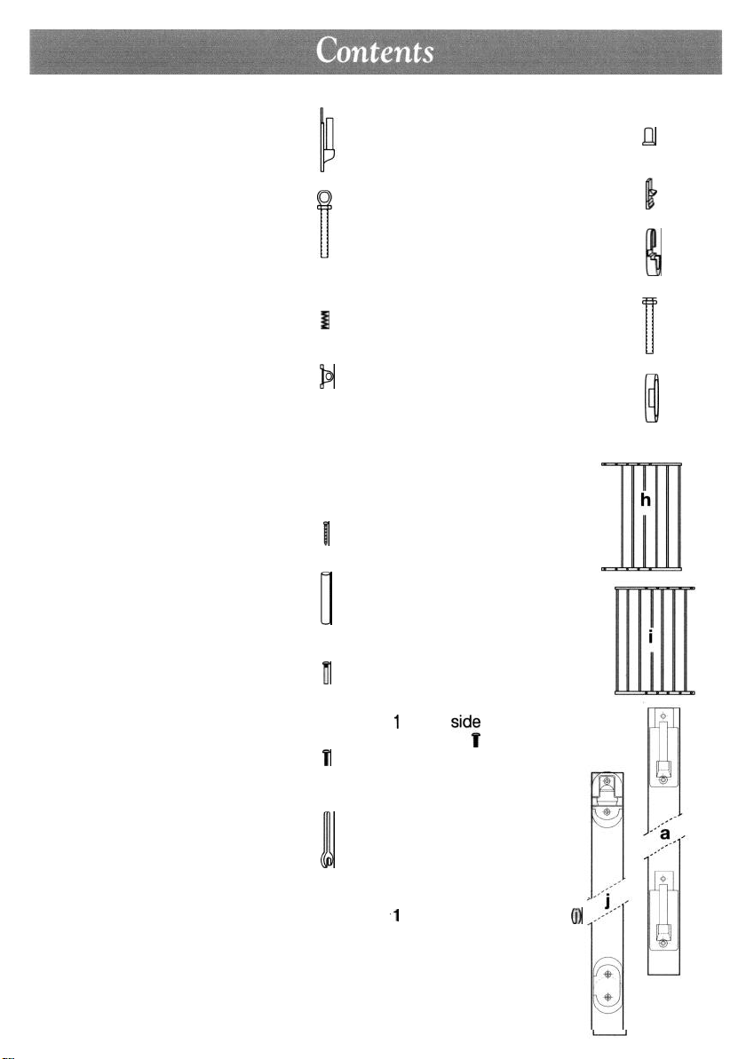
Hinge Side Hardware
Locking Side Hardware
2 Hinge bottoms (b)
2 Hinge spindles with locknuts (c)
1
2 Springs (d)
2 Hinge caps (e)
General Hardware
8 Wood screws (q)
1 Protective plastic cover (r)
4 Expansion screw sockets
(f)
0
I
b
I
u
u
1 Stop pin (s)
1 Locking latch (k)
1 Locking latch bracket (I)
2 Latch spindles with locknut (m)
1 Botton locking bracket (p)
1 Gate section
with 6 bars (h)
1 Gate section
with 7 bars (i)
L4
II
w
v
l!l
4 Expansion screws (g)
1 Wrench (n)
1
Hinge sid; template (a)
f
Templates are precise. Due to size
they are not intemet reproducible.
Please contact customer service
for replacement templates.
I!!
‘1
Locking side template
(i)
Page 4

Important. Gate must be installed in a
structurally sound opening. Hinge side of
gate must be mounted to a rigid surface.
Ensure mounting surface (wall, door frame,
stairpost etc.) is strong, rigid and has an even
surface.
If using gate on a stairway, it must be placed
either on top stair or on lowest stair at the
bottom.
Mounting Hinge Side
Screws provided are for mounting directly
into wood. If mounting into brick, drywall
or other surfaces, use appropriate hardware. If installing into hardwood
(i.e. oak), drilling a pilot hole may be
necessary.
Hold template (a) against mounting surface,
“1”
making sure end marked
floor.
Mark 4 screw hole positions.
Remove template.
is even with
Using 2 wood screws (q) and only lower
screw holes, mount hinge bottoms (b) with
posts pointing up. Top screw holes will be
used later.
Page 5

Screw hinge spindles (c) into top and bottom
rails of gate section (h) until they are extended equally. These will be adjusted to the
correct length at a later stage so do not
tighten.
Repeat process on gate section (i) using latch
spindles (m).
Mounting Locking Side
Screws provided are
into wood. If mounting into brick, drywall
or other surfaces, use appropriate hardware. If installing into hardwood (i.e. oak),
drilling a pilot hole may be necessary.
Hold template
line with opposite hinges, making sure end
marked
Mark 4 screw hole positions.
Remove template.
Determine which direction the gate should
open. For stairways, gate should never
open out over stairs.
Using 2 screws (q), screw bottom locking
bracket (p) into lower set of screw holes with
opening side facing direction gate will open.
(j)
against mounting surface
“1”
is even with floor.
for
mounting directly
in
Fit locking latch (k) into locking latch bracket
(l).
5
Page 6

As an added safety measure, a stop pin has
been provided. Insert stop pin (s) from behind
locking latch bracket into hole oppo-site ope-
ning direction. Using 2 screws, screw into
upper set of screw holes.
Correct width will be reached by adjusting
gate sections and all four corner spindles.
Each spindle adjusts individually and may be
extended to varying lengths to allow for molding, uneven walls, etc. Spindles may be
extended a minimum of 1” but not more than
3”
on each side.
Adjust gate sections, until gate is approximat-
ely right width and adjustment holes are aligned on top and bottom. Sections should fit
without any distance between bars.
Gate sections must not be extended any
further than 4 adjustment holes from spind-
le ends of gate and holes must overlap at
two places on both top and bottom railing.
Place one set of expansion screws and screw
sockets (f & g) in top and bottom set of overlapping adjustment holes nearest hinge side
of gate and second set of expansion screws
and screw sockets in overlapping holes nearest locking side of gate. Tighten with a
screwdriver.
6
Page 7

Min: 1”
Max:
3”
Center gate in opening. Gaps on each side
should be equal.
Place hinge spindles (c) over hinge bottom
posts (b), dropping them into place. Adjust
latch spindles (m) out until they fit securely
into two locking brackets. Latch spindle at
top must be adjusted so it clicks under
locking latch when in closed position.
Space between end of gate and mounting
surface should be no less than 1” and not
more 3” on each side.
Check that gate can be easily opened and
closed without catching.
Place a spring (d) and hinge cap (e) on each
hinge post. This may require some manipulation to ensure hinge posts fit and holes line
up. Insert remaining 2 screws and tighten.
With wrench (n) tighten lock nuts on all
spindles towards gate.
WARNING. Spring must be placed OVER
hinge spindle and hinge cap must be
installed as directed.
7
Page 8

1
I I
I I
A protective plastic cover (r) is provided for
top latch spindle. Cut cover, remove latch
spindle and put cover on. Return spindle and
adjust to correct length.
I I
I I
8
Page 9

To open gate, press down on locking latch
with thumb, lift gate and slide out of upper
and lower locking brackets.
Note. Gate should always be in locked
position. If gate is open and excessive
pressure is applied, hinge posts are designed to break to prevent structural dama-
ge.
To lock gate, latch spindle at top must click
* No part of this gate requires lubrication.
l Clean by sponging with warm water and
mild detergent.
l
Do not use abrasive cleaners or bleach.
l
If using outdoors, and to help prevent rust,
treat all exposed metal with a rust inhibitor. Some rusting may still occur.
under locking latch when in closed position.
Bottom latch spindle must rest in bottom
bracket.
9
Page 10

KIDCO LIMITED WARRANTY
Your KidCo product is warranted to be free from manufacturing defects for a period of one
year from date of purchase under normal use and in compliance with the operating instructions. This warranty extends only to the original retail purchaser and is only valid when sup-
plied with proof of purchase.
KidCo will either repair, or at our option replace, free of charge, any parts necessary to correct
defects in material or workmanship during the warranty period. This warranty is complete and
exclusive. The warranty expressly disclaims liability for incidental, special and consequential
damages of any nature. Any implied warranty arising by operation of law shall be limited in
operation to the terms of this warranty. Some states do not allow the exclusion or limitation of
incidental or consequential damages or limitations on how long an implied warranty lasts, so
the above may not apply to you. This warranty gives you specific legal rights, and you may
have other rights which vary from state to state.
SHOULD REPAIR OR PARTS BE NECESSARY
Should a repair be needed during the warranty period, ship the gate in the original carton or
similar protective container (check any retail store or purchase from UPS) and send freight
prepaid (we suggest UPS) to: KidCo, Inc., 1013 Technology Way, Libertyville, IL 60048.
include a note with your return address, day-time telephone number, and specify what is
wrong with the product. Repairs can normally be made within 48 hours after receipt at KidCo.
For additional information CALL our customer service department at (800) 553-5529.
.
10
 Loading...