

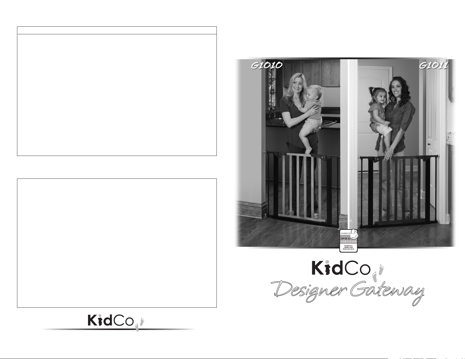
Kidco G1011 User Manual [en, es, fr]
Extension Placement Guide/Guía de colocación de las extensiones
G4101 and G4111 Extension Guide for Gateway Models G1010 and G1011
Note: Each G4101 kit contains two extensions
•
Each G4110/G4111 kit contains one extension
Width Opening Extensions What You Need Placement
29”– 31 ½” Basic Gate No extensions
31 ½” – 34 ½” Included with Gate Gate + 1 extension -1 on one end
34 ½” – 37” Gate + 2 extensions -1 on each end
37” – 40” 1-G4101 Gate + 3 extensions -2 on one end; 1 on other end
40” – 42 ½” Gate + 4 extensions -3 on one end; 1 on other end
42 ½” – 45” 2-G4101 Gate + 5 extensions -3 on one end; 2 on other end
45” – 47 ½” Gate + 6 extensions -3 on each end
47 ½”-49 ½” 1-G4111 Gate + 3 extensions -G4111 on either end;
1 extension on each end
49 ½”-52” 1-G4111 Gate + 4 extensions -1-G4111 + 2 extensions on
+ 1-G4101 one end; 1 extension on other end
52”-55” Gate + 5 extensions -1 G4111 + 2 extensions on
one end; 2 extensions on other end
55”-57” 2-G4111 Gate + 2 extensions -1 G4111 on each end
57”-60” Gate + 3 extensions -1 G4111 on each end;
1 extension on one end
60”-62” Gate + 4 extensions -1 G4111 + 1 extension on each end
62”-65” 2-G4111 Gate + 5 extensions -1-G4111 + 1 extension on
+ 1-G4101 each end; 1 extension on one end
65”-68” Gate + 6 extensions -1 G4111 + 2 extensions on each end
68”-70” 2-G4111 Gate + 7 extensions -1-G4111 + 2 extensions on
+ 2-G4101 each end; 1 extension on one end
70”-73 ½” Gate + 8 extensions -1-G4111 + 3 extensions on each end
Guide de positionnement des rallonges
Guides de rallonge G4101 et G4111 pour Gateway modèles G1010 et G1011
Remarque : Chaque ensemble G4101 contient deux rallonges
Largeur d'ouverture Rallonges Matériel requis Positionnement
73,6 à 80 cm Barrière de base Sans rallonges
80 à 87,6 cm Inclus avec la barrière Barrière + 1 rallonge -1 à une extrémité
87,6 à 93,9 cm Barrière + 2 rallonges -1 à chaque eextrémité
93,9 à 101,6 cm 1-G4101 Barrière + 3 rallonges -2 à une extrémité; 1 à l'autre extrémité
101,6 à 107,9 cm Barrière + 4 rallonges -3 à une extrémité; 1 à l’autre extrémité
107,9 à 114,3 cm 2-G4101 Barrière + 5 rallonges -3 à une extrémité; 2 à l'autre extrémité
114,3 à 120,6 cm Barrière + 6 rallonges -3 à chaque extrémité
120,6 à 125,7 cm 1-G4111 Barrière + 3 rallonges -G4111 à l'une ou l'autre extrémité;
1 rallonge à chaque extrémité
125,7 à 132 cm 1-G4111 Barrière + 4 rallonges -1-G4111 + 2 rallonges à une extrémité;
+ 1-G4101 1 rallonge à l'autre extrémité
132 à 139,7 cm Barrière + 5 rallonges -1 G4111 + 2 rallonges à une extrémité;
2 rallonges à l'autre extrémité
139,7 à 144,7 cm 2-G4111 Barrière + 2 rallonges -1 G4111 à chaque extrémité
144,7 à 152,4 cm Barrière + 3 rallonges -1 G4111 à chaque extrémité;
1 rallonge à une extrémité
152,4 à 157,4 cm Barrière + 4 rallonges -1 G4111 + 1 rallonge à chaque extrémité
157,4 à 165,1 cm 2-G4111 Barrière + 5 rallonges -1-G4111 + 1 rallonge à chaque extrémité;
+ 1-G4101 1 rallonge à une extrémité
165,1 à 172,7 cm Barrière + 6 rallonges -1 G4111 + 2 rallonges à chaque extrémité
172,7 à 177,8 cm 2-G4111 Barrière + 7 rallonges -1-G4111 + 2 rallonges à chaque extrémité;
+ 2-G4101 1 rallonge à une extrémité
177,8 à 186,6 cm Barrière + 8 rallonges -1-4111 + 3 rallonges à chaque extrémité
1013 Technology Way, Libertyville, IL 60048
•
Chaque ensemble G4111 contient une rallonge.
®
800.553.5529
www.kidco.com
USER GUIDE
GUIDE D'UTILISATION
GUÍA DEL USUARIO
G1011G1010
®
Designer Gateway
PRESSURE MOUNT INSTALLATION
Fits openings 29” – 37” • Optional extension kits available
Pour des ouvertures de 73 à 94 cm • Rallonges disponibles en option
Para aberturas de 29” a 37" • Hay disponibles extensiones opcionales
®
USER GUIDE
G1010/G1011
Designer Gateway
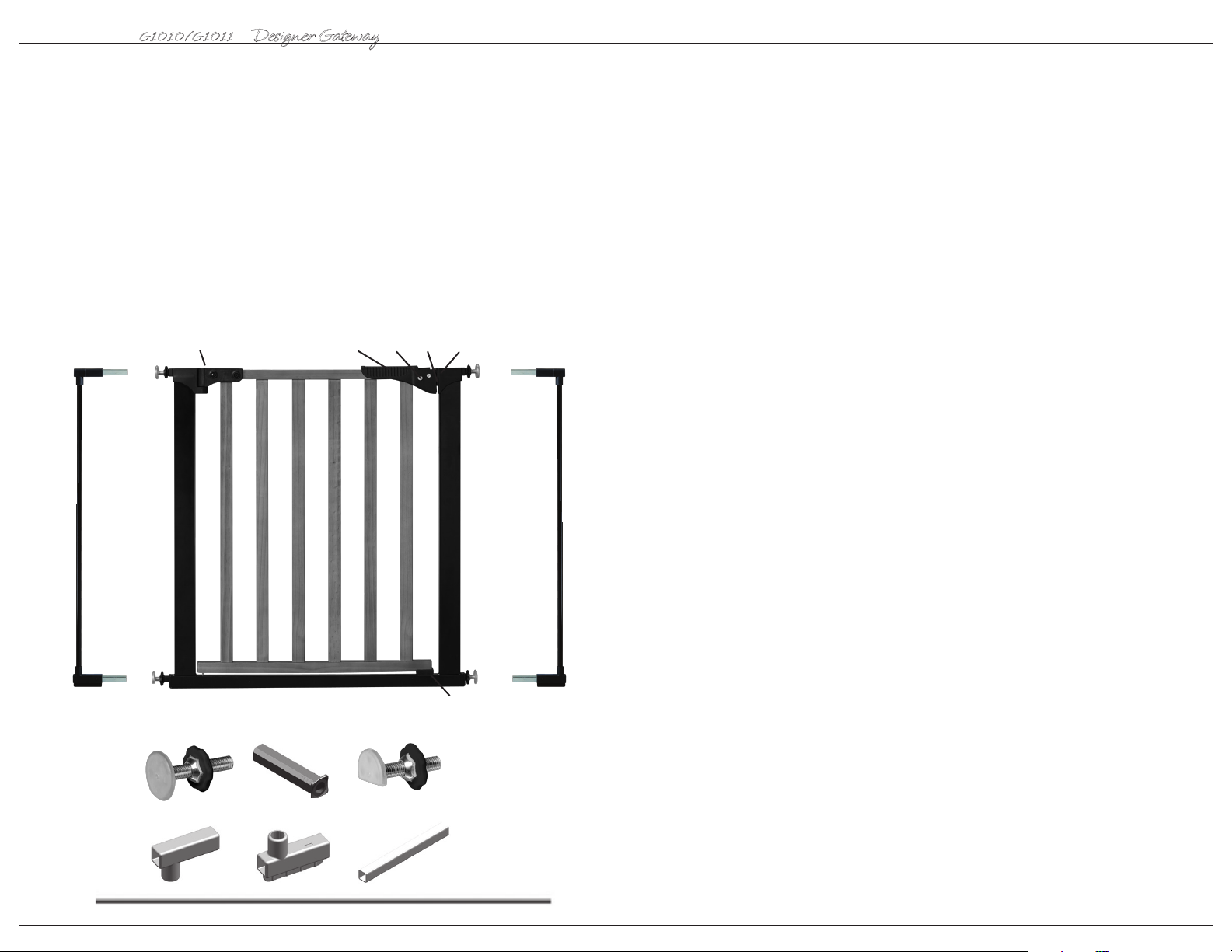
Parts list
A Top Spindle (2)
B Spindle Housing (4)
C Bottom Spindle (2)
D Upper Extension Housing (2)
E Lower Extension Housing (2)
F Extension Tube (4)
G Extension Bar (2)
H Pressure Hinge
I Button (2)
J Pressure Plate
K Handle
L Hinge
M Locator
®
KL
IHJ
M
A
B
E
C
FD
G
2
23
USER GUIDE
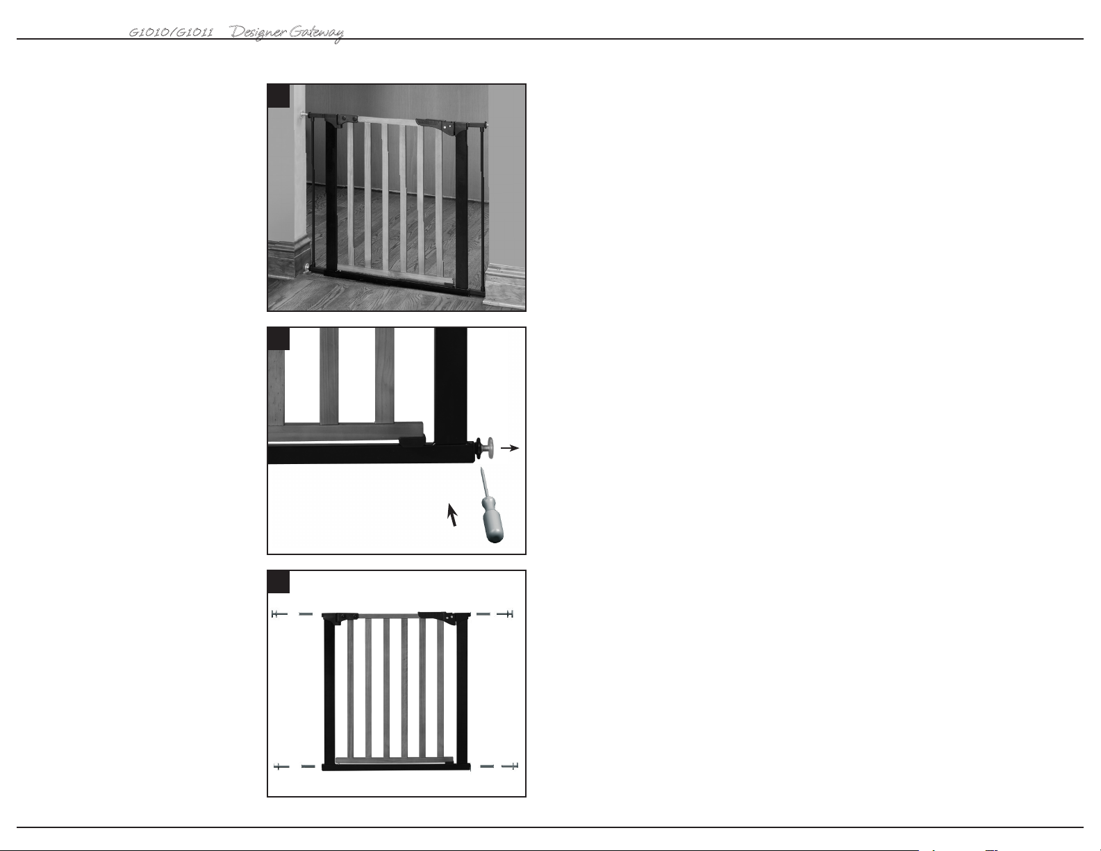
Installation
G1010/G1011
Designer Gateway
®
1 The gate must be installed in a
structurally sound opening. Ensure
mounting surface (wall, doorframe, etc.) is
strong, rigid and is smooth, clean and
grease free. If mounting onto brick, drywall
or other surfaces, an optional gate
installation kit, wooden board mounted to
the surface or additional hardware may be
necessary to provide a solid, smooth
surface. Measure opening to determine if
extensions are needed. Correct width will
be reached by adjusting all 4 corner
spindles. Each spindle adjusts individually
and may be extended to varying lengths
(up to 1 ¾” each) to allow for molding,
uneven walls, etc. This gate can be used
in a closed doorway. Never use gate at top
of stairs.
2 Spindle attachment is different
when using extensions and when not
using extensions. Spindle housings are
not used if square extension tubes are
required. If the housings have been
inserted, remove with a screwdriver.
1
2
3 If no extension/s are used, slide top
spindles (a) and bottom spindles (c) into
spindle housing end (b). Push assembly
into gate corners.
4
3
(a) (b) (b) (a)
(c) (b) (b) (c)
21
USER GUIDE
G1010/G1011
Designer Gateway
®
G1010/G1011
Designer Gateway
®
GUÍA DEL USUARIO
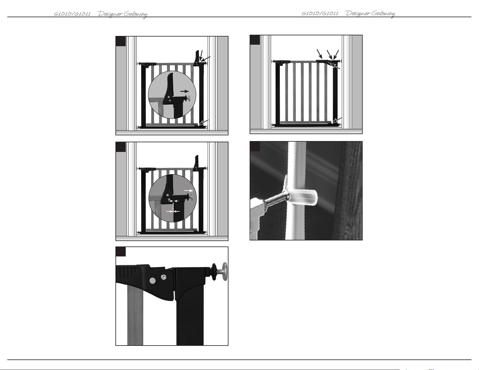
7 With handle in upright position, close
walk through door so pressure plate (l) is
aligned with pressure hinge (h) and the
locator (m) is resting on the bottom bar.
Pull out the top two spindles (a) until they
touch mounting surfaces. Alternating
sides, tighten handwheels TOWARD GATE
FRAME making sure the distance to the
mounting surface on each side is equal.
8 Tighten handwheels so that the
distance between the pressure plate (l)
and pressure hinge (h) is
should still be in upright position.
1
/32”. Handle
7
(l)
(h)
10
(k)
(l)
(h)
10 a) ) Para abrir la reja, libere el mecanis-
mo de bloqueo presionando los dos botones
(i) en la manija de elevación.
b) Para cerrar la reja, levante la puerta de
(i)
acceso. Alinee la placa de presión (l) con la
bisagra de presión (h). Baje la puerta
asegurándose de que el localizador (m) esté
(a)
apoyado sobre la barra superior y presione
la manija (k) hacia abajo para bloquearla.
(m)
8
11
(m)
11 Instalación: KidCo tiene disponibles
pivotes Y OPCIONALES (Modelo GY-1) para
asistir en la instalación cuando la superficie
de montaje tiene un balaustre redondo.
Estos ejes se usan en lugar de los que se
(a)
(l) (h)
incluyen con la reja básica. Se pueden pedir
en una concesionaria KidCo de su localidad
o directamente de KidCo. Retire la ruedecilla
de la tuerca del pivote de la reja, e instálela
1
/32”
en la tuerca del pivote en Y antes de instalar
el pivote en Y en el extremo de la reja.
9 Push down on handle to lock the door
and check all hardware. If correctly
installed, the gate should be firmly in place.
Once opened, the walk through door
should operate easily in either direction.
6
9
19
 Loading...