

Kidco Elongate G60c User Manual
Elongate® Model G60c
for openings 45”-59” wide
Maximum 4 extensions per gate.
Modèle G60c Elongate® pour ouvertures de 1,1 à 1,5 m de largeur
4 rallonges maximum par barrière.
Reja Elongate® Modelo G60c para aberturas de 45”- 59” de ancho
Máximo de 4 extensiones por reja.
Bl. 3001-386b • G60c-0407
User Guide
Patents
Pending
3001-386b-G60.indd 3 27/07/04 9:37:16
INDEX
Adjustment holes
Trous de réglage
Orificios de ajuste
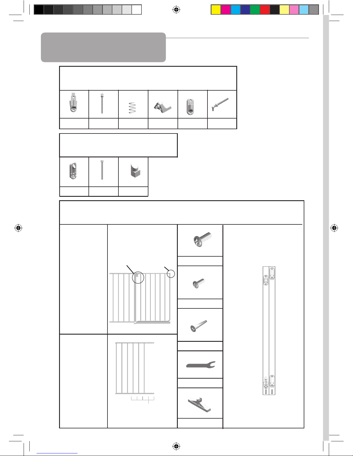
Parts Check List
Liste de contrôle des pièces
Lista de verificación de piezas
Hinge Side Hardware
Quincaillerie côté charnières
Herraje del lado de la bisagra
(c) - 1 (d) - 1 (e) - 1 (f) - 1 (g) - 1 (h) - 1
Locking Side Hardware
Quincaillerie côté verrouillage
Herraje del lado del mecanismo de cierre
(l) - 2 (n) - 1 (o) - 1
General Hardware
Quincaillerie générale
Herraje general
Hinge
Charnière
Bisagra
a
b
1 Hinge side template (a)
1 Pochoir côté charnières (a)
1 Plantilla para el lado de la
bisagra (a)
1 Main Gate
section with
walk through
section.
1 Section de
barrière
principale
avec portail.
1 Sección
principal de la
reja con
abertura para
la puerta.
1 Second section
1 Seconde
section
1 Segunda
sección
1 Locking side template (b)
1 Pochoir côté verrouillage (b)
1 Plantilla para el lado del
mecanismo de cierre (b)
(i) - 4
(j) - 4
(k) - 8
(r) - 1
2
Latch spindle
already fitted
Axe de loquet
déjà installé
Pivote del mecanismo de cierre ya
ajustado
Walk through
section
Section
Portail
Sección
de acceso
(p) - 1
3001-386b-G60.indd 4 27/07/04 9:37:19

INDEX
User Guide
Parts Check List . . . . . . . . . . . . . . . . . . . . . . . . . . . . . . . 2
Elongate® Model G60c . . . . . . . . . . . . . . . . . . . . . . . . . 4-6
Warranty. . . . . . . . . . . . . . . . . . . . . . . . . . . . . . . . . . . . . 6
Parts Price List . . . . . . . . . . . . . . . . . . . . . . . . . . . . . . . . 15
Method of Payment . . . . . . . . . . . . . . . . . . . . . . . . . . . . 16
Illustrations . . . . . . . . . . . . . . . . . . . . . . . . . . . . . . . . . . . 19-21
Guide d’utilisation
Liste de Contrôle des Pièces . . . . . . . . . . . . . . . . . . . . . 2
Modèle G60c Elongate® . . . . . . . . . . . . . . . . . . . . . . . . 7-9
Garantie . . . . . . . . . . . . . . . . . . . . . . . . . . . . . . . . . . . . . 10
Liste des prix des piéces . . . . . . . . . . . . . . . . . . . . . . . . 15
Mode de Paiement . . . . . . . . . . . . . . . . . . . . . . . . . . . . . 17
Figures . . . . . . . . . . . . . . . . . . . . . . . . . . . . . . . . . . . . . . 19-21
Guía del usuario
Lista de Verificación de Piezas . . . . . . . . . . . . . . . . . . . 2
Reja Elongate® Modelo G60c . . . . . . . . . . . . . . . . . . . . 11-13
Garantía . . . . . . . . . . . . . . . . . . . . . . . . . . . . . . . . . . . . . 14
Lista de precious de las piezas . . . . . . . . . . . . . . . . . . . 15
Metodo de Pago . . . . . . . . . . . . . . . . . . . . . . . . . . . . . . 18
Ilustraciones . . . . . . . . . . . . . . . . . . . . . . . . . . . . . . . . . . 19-21
ENG
FRE
SPA
3
3001-386b-G60.indd 5 27/07/04 9:37:20

Installation
4
FOLLOW THESE
INSTRUCTIONS
CAREFULLY AND
KEEP THEM FOR
FUTURE
REFERENCE
This gate is designed for children from 6 months
to 24 months. Since each child’s skills develop
at different ages, these age parameters should
be monitored against your child’s own development.
Use 1 optional 24” extension (Model G24c) when
opening is 5’ to 7’ wide.
Use 2 optional 24” extensions (Model G24c) when
opening is 7’ to 9’ wide.
Use 3 optional 24” extensions (Model G24c) when
opening is 9’ to 11’ wide,
Use 4 optional 24” extensions (Model G24c) when
opening is 11’ to 13’ wide.
Maximum 4 extensions per gate.
• No part of this gate requires lubrication.
• Clean by sponging with warm water and
mild detergent.
Important Information
Maintenance
WARNING
• Intended for use with children from 6
months through 24 months.
• Check the stability of the gate and tighten
all hardware and mountings regularly.
• To prevent serious injury or death,
securely install gate or enclosure and use
according to manufacturer’s instructions.
• Never use with a child able to climb over or
dislodge/open the gate or enclosure.
• Do not use if any part of the gate is broken
or missing.
• Never use if gate is less than 3/4 of child’s
height.
• Discontinue use if any part of gate is
damaged.
• This product will not necessarily prevent all
accidents. Never leave child unattended.
• Use only spare parts available from KidCo.
• Never allow child to climb or swing on gate.
• Use only with the locking/latching
mechanism securely engaged.
• Never use gate at top of stairs.
• Never climb over the gate.
• Never hang or tie toys etc. to any part of
the gate.
ENG
• Do not use abrasive cleaners or bleach.
• If using outdoors, and to help prevent rust,
treat gate with a rust inhibitor. Some rusting
may still occur.
3001-386b-G60.indd 6 27/07/04 9:37:20

1. Important. Gate must be installed in a
structurally sound opening. The hinge side of
gate must be mounted to a rigid surface.
Ensure mounting surface (wall, door frame,
stairpost, etc.) is strong, rigid and has an even
surface.
If using gate on a stairway, it must be placed on
lowest stair at the bottom.
2. The correct width will be achieved by
adjusting gate sections and all four corner
spindles. Each spindle adjusts individually and
may be extended varying lengths to allow for
molding, uneven walls, etc. Spindles may be
extended a minimum of 11/4” (hinge side) or 1”
(on locking side) and a maximum of 3”.
3. Adjust sections until gate is approximately
the correct width and adjustment holes are
aligned and overlap in two places on both the
top and bottom rail. Gate sections must not be
extended any further than 4 adjustment holes
from spindle ends of gate.
Sections should fit without any distance
between rails or bars.
4. Place screws (i) and screw sockets (j) in top
and bottom sets of overlapping adjustment
holes nearest hinge and locking sides of gate.
Do not fully tighten yet.
5. Screw upper hinge spindle (h) into top rail of
second gate section.
Screw lower hinge spindle (d) into bottom rail of
same side.
Extend spindles equally.
6. Slide locking latch spindle (n) into bottom rail
of main gate section.
Extend spindles equally.
Final spindle adjustments will be made later.
7. Hinge Side Mounting
Screws provided are for mounting directly
into wood. If mounting into brick, drywall or
other surfaces, use appropriate hardware. If
installing into hardwood, (i.e. oak), drilling a
pilot hole may be necessary.
Cut out templates along all dotted lines,
separating template (a) from (b).
Hold template (a) vertically and completely
outstretched against mounting surface with the
end marked “ ” even with the floor.
Mark 4 screw hole positions.
Remove template.
8. Using 2 wood screws (k), mount upper hinge
(g) (with hole pointing up) in top 2 screw hole
positions.
9. Using 2 wood screws (k), mount lower hinge
bottom (c) (with post pointing up) in bottom 2
screw hole positions.
10. Locking Side Mounting
Screws provided are for mounting directly
into wood. If mounting into brick, drywall or
other surfaces, use appropriate hardware. If
installing into hardwood, (i.e. oak), drilling a
pilot hole may be necessary.
Hold template (b) vertically and completely
outstretched against mounting surface with the
end marked “ ” even with the floor.
Mark 4 screw hole positions.
Remove template.
11. Determine which direction the gate should
open. Insert stop pin (o) from behind in hole of
one locking latch bracket (l) opposite desired
opening direction.
Important: The gate cannot open to the stop
pin side.
12. Using 2 wood screws (k) mount locking
latch bracket with stop pin (l) in top 2 screw
hole positions.
Using 2 wood screws (k), mount second locking
latch bracket (l) in bottom 2 screw hole
positions.
13. Push stabilizing foot (r) into vertical tube.
Use of stabilizing foot is optional unless one
or more (maximum 4) optional extensions are
used.
14. Center gate in opening. Adjust upper hinge
spindle (h) so post fits into upper hinge hole (g).
15. Adjust lower hinge spindle (d) so end fits
over lower hinge post (c). Space between end
of gate and mounting surface on hinge side may
be no less than 11/4” and not more than 3”.
16. Adjust locking latch spindles (n) until they
fit securely into both latch brackets. Spindles
must click under locking latch when in the
closed position. Space between end of gate
and mounting surface on locking side may be
no less than 1” and not more than 3”.
Installation
5
➤
➤
3001-386b-G60.indd 7 27/07/04 9:37:20

Remarques importantes
Entretien
ATTENTION
6
Installation
17. If adjusting the spindles does not achieve
the correct length, it may be necessary to lift
gate off hinges and readjust the sections (see
step 3).
Check that gate can be smoothly opened and
closed.
18. Place spring (e) on lower hinge post.
19. Place lower hinge cap (f) on lower hinge and
push down until it clicks into locked position.
IMPORTANT. ENSURE HINGE CAP CANNOT
BE PUSHED UP AND IS LOCKED IN PLACE.
20. Using Phillips head screwdriver, tighten
all screws and screw sockets.
With wrench (p), securely tighten all 4 lock nuts
toward the gate.
21. Operation
To open walk through section, press down on
top locking latch, lift walk through section so
hinge is raised (a), and slide out of bracket.
To close gate, lift walk through section and
position safety foot onto frame, making sure
hinge has dropped down (b). To lock gate, latch
spindle at top must click under locking latch.
NOTE. GATE SHOULD ALWAYS BE IN THE
LOCKED POSITION. IF GATE IS OPEN AND
EXCESSIVE PRESSURE IS APPLIED, (SUCH
AS STANDING OR SWINGING ON THE GATE)
STRUCTURAL DAMAGE MAY OCCUR.
22. The gate may be removed by pressing back
on the locking tab on top of lower hinge
bottom while sliding the hinge cap up. Remove
spring and lift gate off top and bottom hinges.
FOR SAFETY REASONS, RETURN SPRING
AND HINGE CAP ONTO HINGE POST,
MAKING SURE CAP IS LOCKED IN PLACE.
Warranty
KIDCO LIMITED WARRANTY
Your KidCo product is warranted to be free from manufacturing defects for a period of one year
from date of purchase under normal non commercial use and in compliance with the operating
instructions. This warranty extends only to the original retail purchaser and is only valid when
supplied with proof of purchase.
KidCo will either repair, or at our option replace, free of charge, any parts necessary to
correct defects in material or workmanship during the warranty period. This warranty is
complete and exclusive. The warranty expressly disclaims liability for incidental, special and
consequential damages of any nature. Any implied warranty arising by operation of law shall be
limited in operation to the terms of this warranty. Some states do not allow the exclusion or
limitation of incidental or consequential damages or limitations on how long an implied warranty
lasts, so the above may not apply to you. This warranty gives you specific legal rights, and you
may have other rights which vary from state to state.
SHOULD REPAIR OR PARTS BE NECESSARY
Should a repair be needed during the warranty period, ship the gate in the original carton or
similar protective container (check any retail store or purchase from UPS) and send freight
prepaid (we suggest UPS) to:
KidCo, Inc., 1013 Technology Way, Libertyville, IL 60048-5349.
Include a note with your return address, day-time telephone number, and specify what is wrong
with the product. Repairs can normally be made within 48 hours after receipt at KidCo. For
additional information CALL our customer service department at (800) 553-5529.
3001-386b-G60.indd 8 27/07/04 9:37:21
 Loading...