

Kidco Center Gateway G15d, Gateway G16a User Manual
The Gateway ® Series
Center Gateway Model G15d / Extra Tall Center Gateway Model G16a
For openings 29” to 37”
Optional extension kits available
Gateway Central Modele G15d / Center Gateway Extra-Hout Modele G16a
Pour overtures de 73.6 a 94 cm
Ensembles de rallonges facultatifs disponibles
Reja Center Gateway Modelo G15d / Reja Center Gateway Extra Alta Modelo G16a
Para aberturas de 29” – 37”
Hay disponibles juegos de extension opcionales
Bl. 3001-816 a • G15d / G16a-0636
User Guide
Patents
6,370,823
6,301,832
6,308,462
6,347,483
5,396,732
G15d
G16a
INDEX
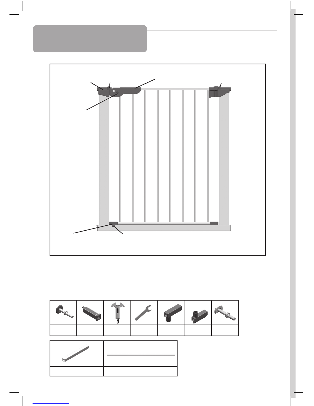
Parts Check List
Liste de contrôle des pièces
Lista de verificación de piezas
(b) - 4 (c) - 4 (d) - 1 (g) - 1 (h) - 2 (i) - 2
(j) - 4 (k) - 2
Note: To prevent over extension
of spindles, notches have
intentionally been cut into the
threads approximately 1
3/8” from
the pad ends.
Remarque: Pour empêcher la
surextension des axes, des crans
ont été intentionnellement
découpés dans les filets, à 3,5 cm
environ des extrémités
rembourrées.
Nota: Para evitar la extensión
excesiva de los pivotes,
intencionalmente se han hecho
ranuras en las roscas a
aproximadamente 1
3/8” de los
extremos de las almohadillas.
2
Pressure Hinge (p)
Charnière à pression (p)
Bisagra de presión (p)
Stopper (q)
Butée (q)
Tope (q)
Locator (l)
Repère (l)
Localizador (l)
Pressure plate (o)
Plaque de pression (o)
Placa de presión (o)
Button (r)
Bouton (r)
Botón (r)
Handle (n)
Poignée (n)
Asa (n)
Hinge (m)
Charnière (m)
Bisagra (m)
Gate
Barrière
Reja
(s) - 2

INDEX
User Guide
Parts Check List ............................... 2
Center Gateway® Gate Model G15d /
Extra Tall Center Gateway ® Model G16a ........... 4-6
Warranty..................................... 6
Parts Price List ................................ 15
Method of Payment ............................ 16
Illustrations ................................... 20-21
Guide d’utilisation
Liste de Contrôle des Pièces ..................... 2
Gateway® central modèle G15d /
Center Gateway Extra-Haut G16a ................. 7-9
Garantie ..................................... 10
Liste des prix des piéces ........................ 15
Mode de Paiement ............................. 17
Figures ...................................... 20-21
Guía del usuario
Lista de Verificación de Piezas ................... 3
Reja Center Gateway® Modelo G15d /
Reja Center Gateway Extra Alta G16a.............. 11-13
Garantía ..................................... 14
Lista de precious de las piezas ................... 15
Metodo de Pago .............................. 18
Ilustraciones .................................. 20-21
SPA
FRE
ENG
3

4
FOLLOW THESE
INSTRUCTIONS
CAREFULLY AND
KEEP THEM FOR
FUTURE
REFERENCE
This gate is designed for children from 6 months to 24
months. Since each child’s skills develop at different
ages, these parameters should be monitored against
your child’s own development.
When installed as instructed, between two clean
structurally sound surfaces, this gate conforms to:
ASTM F-1004-07 United States Standards
EN 1930:2000 European Standards
• No part of gate requires lubrication.
• Clean using warm, soapy water or a damp cloth.
Important Information
Maintenance
WARNING
• Intended for use with children from 6 months
through 24 months.
• Check the stability of the gate and tighten all
hardware and mountings regularly.
• To prevent serious injury or death, securely install
gate or enclosure and use according to
manufacturer’s instructions.
• Never use with a child able to climb over or
dislodge/open the gate or enclosure.
• Never use if gate is less than 3/4 of child’s height.
• Do not use if any part of the gate is broken or missing.
• This product will not necessarily prevent all
accidents. Never leave child unattended.
• Use only spare parts available from KidCo.
• Never allow child to climb or swing on gate.
• Use only with the locking/latching mechanism
securely engaged.
• Never use gate at top of stairs.
• Discontinue use if any part of gate is damaged.
• Never climb over the gate.
• Never hang or tie toys etc. to any part of the gate.
ENG
• Do not use abrasive cleaners or bleach.
• If using outdoors, and to help prevent rust, treat
gate with a rust inhibitor.
Some rusting may still occur.
Extension Placement Guide

1. The gate must be installed in a structurally sound
opening. Never install between two railings or two stair
posts.
Ensure mounting surface (wall, doorframe, stair post,
etc.) is strong, rigid and is smooth, clean and grease
free.
If mounting onto brick, drywall or other surfaces,
an optional gate installation kit, wooden board
mounted to the surface or additional hardware may
be necessary to provide a solid, smooth surface.
Measure opening to determine if extensions are
needed. Correct width will be reached by adjusting all
4 corner spindles. Each spindle adjusts individually
and may be extended to varying lengths (up to 13/4”
each) to allow for molding, uneven walls, etc.
If using gate on a stairway, it must be placed on the
lowest stair on bottom.
2. Spindle attachment is different when using
extensions and when not using extensions.
If no extension/s are used, slide top spindles (b) and
bottom spindles (s) into spindle housing end with out
tab (c). Push assembly into gate corners.
3. If using extension/s, (see Extension Placement
Guide) insert square extension tubes (j) into gate ends.
Connect the bar (k) to one upper extension housing (h)
and one lower extension housing (i). Push assembly
over extension tubes.
There should be no metal showing from extension
tubes. It may be necessary to apply pressure to tubes
to ensure they are fully inserted into gate ends. Slide
top spindles (b) and bottom spindles (s) into extension
tubes.
4. Note:
Spindle housings are not used if square extension
tubes are necessary. If the housings have been
inserted, remove with a screwdriver.
5. Center the gate in opening with bottom rail resting
on floor. Gaps on each side should be equal.
Open the handle to the raised position by pressing the
button (r) and lifting the handle (n) at the same time.
BUTTON MUST ALWAYS BE PRESSED IN WHEN
LIFTING HANDLE.
FAILURE TO DO SO WILL RESULT IN HANDLE
MECHANISM BREAKING.
Installation
5
Extension Placement Guide
G5.5 and G12.5 Extension Placement Guide for Center Gateway (Model G15)
and Extra Tall Center Gateway (Model G16)
Note: Each G5.5 Kit contains two extensions Note: Each G12.5 Kit contains one extension
Width Opening Extensions What You Need Placement
29” – 31 ½” Basic Gate No extensions
31 ½” - 34 ½” Included with Gate Gate + 1 extension -on one end
34 ½” – 37” Gate + 2 extensions -1 on each end
37” – 40” 1 G5.5 Kit Gate + 3 extensions -2 on one end; 1 on other end
40” – 42 ½” Gate + 4 extensions -3 on one end; 1 on other end
42 ½” – 45” 2 G5.5 Kits Gate + 5 extensions -3 on one end; 2 on other end
45” – 47 ½” Gate + 6 extensions -3 on each end
47 ½” – 49 ½” 1 G12.5 Gate + 3 extensions -G12.5 on either end; 1 extension on each end
49 ½” – 52” 1 G12.5 + 1 G5.5 Kit Gate + 4 extensions - 1 G12.5 + 2 extensions on one end;
1 extension on other end
52” – 55” Gate + 5 extensions - 1 G12.5 + 2 extensions on one end;
2 extensions on other end
55” – 57” 2 G12.5 Gate + 2 extensions -1 G12.5 on each end
57” – 60” Gate + 3 extensions -1 G12.5 on each end; 1 extension on one end
60” – 62” Gate + 4 extensions -1 G12.5 + 1 extension on each end
62” – 65” 2 G12.5 + 1 G5.5 Kit Gate + 5 extensions - 1 G12.5 + 1 extension on each end;
1 exten
sion on one end
65” – 68” Gate + 6 extensions -1 G12.5 + 2 extensions on each end
68” – 70” 2 G12.5 + 2 G5.5 Kits Gate + 7 extensions -
1 G12.5 + 2 extensions on each end;
1 extension on other end
70” – 73 ½” Gate + 8 extensions -1 G12.5 + 3 extensions on each end
Each end may have no more than 4 extensions.
Extensions must be added as shown.
Remarques importantes
Entretien
ATTENTION
6
Operation
6. Pull out the two bottom spindles (s) until they touch
mounting surface and rest on top of floor molding (if
applicable). Tighten nuts TOWARD GATE FRAME as
tightly as possible using wrench (g) provided. Each
spindle adjusts individually and may be extended to
varying lengths to allow for molding, uneven walls, etc.
7. Close walk through door so locator (l) is aligned
directly above bottom gate rail. Do not lower handle.
Pull out the top spindle (b) on the hinge side (m) until it
touches the mounting surface. Tighten nut TOWARD
GATE FRAME until locator drops and rests on bottom
gate rail.
8. Pull out spindle (b) in the handle side until it touches
mounting surface and tighten nut TOWARD GATE
FRAME so the distance between pressure plate o) and
pressure hinge (area A) is sufficient for walk through
door to open in either direction.
9. Close the handle and check all hardware.
If correctly installed, gate should be firmly in place.
Once opened, the walk through door should operate
easily in either direction.
A pressure indicator (d) has been included as an
additional safeguard. Lift handle (n) and locate groove
on underside. Return handle to closed position and
place indicator hook under groove. Push in button
(r) while pulling pressure indicator up. Black gauge
within indicator will start moving down. Recommended
pressure is between 3 and 5. If gauge is more than 5,
loosen nut on handle spindle (b). If less than 3, tighten
handle spindle nut.
If unable to obtain recommended pressure, it is
important to know that gate is not defective. Gate
requires a strong, rigid surface to maintain pressure.
It may be necessary to consult a hardware store or
baby proofer to find a solution for safe installation.
Warranty
KIDCO LIMITED WARRANTY
Your KidCo product is warranted to be free from manufacturing defects for a period of one year from date of
purchase under normal non commercial use and in compliance with the operating instructions. This warranty
extends only to the original retail purchaser and is only valid when supplied with proof of purchase.
KidCo will either repair, or at our option replace, free of charge, any parts necessary to correct defects in
material or workmanship during the warranty period. This warranty is complete and exclusive. The warranty
expressly disclaims liability for incidental, special and consequential damages of any nature. Any implied
warranty arising by operation of law shall be limited in operation to the terms of this warranty. Some states
do not allow the exclusion or limitation of incidental or consequential damages or limitations on how long an
implied warranty lasts, so the above may not apply to you. This warranty gives you specific legal rights, and
you may have other rights which vary from state to state.
SHOULD REPAIR OR PARTS BE NECESSARY
Should a repair be needed during the warranty period, ship the gate in the original carton or similar protective
container (check any retail store or purchase from UPS) and send freight prepaid (we suggest UPS) to:
KidCo, Inc., 1013 Technology Way, Libertyville, IL 60048-5349.
Include a note with your return address, day-time telephone number, and specify what is wrong with the product.
Repairs can normally be made within 48 hours after receipt at KidCo. For additional information CALL our
customer service department at (800) 553-5529.
Installation
10. To Open Gate.
Release locking mechanism by pressing button (r)
in while lifting handle. BUTTON MUST ALWAYS BE
PRESSED IN WHEN LIFTING HANDLE. Lift walk
through door so hinge is raised and door will swing
open in either direction.
To Close Gate.
Lift walk through door. Position locator (l) until it is
above the bottom rail. Make sure hinge has dropped
down. Push handle down to lock.
Gate should always be in locked position when in
use.
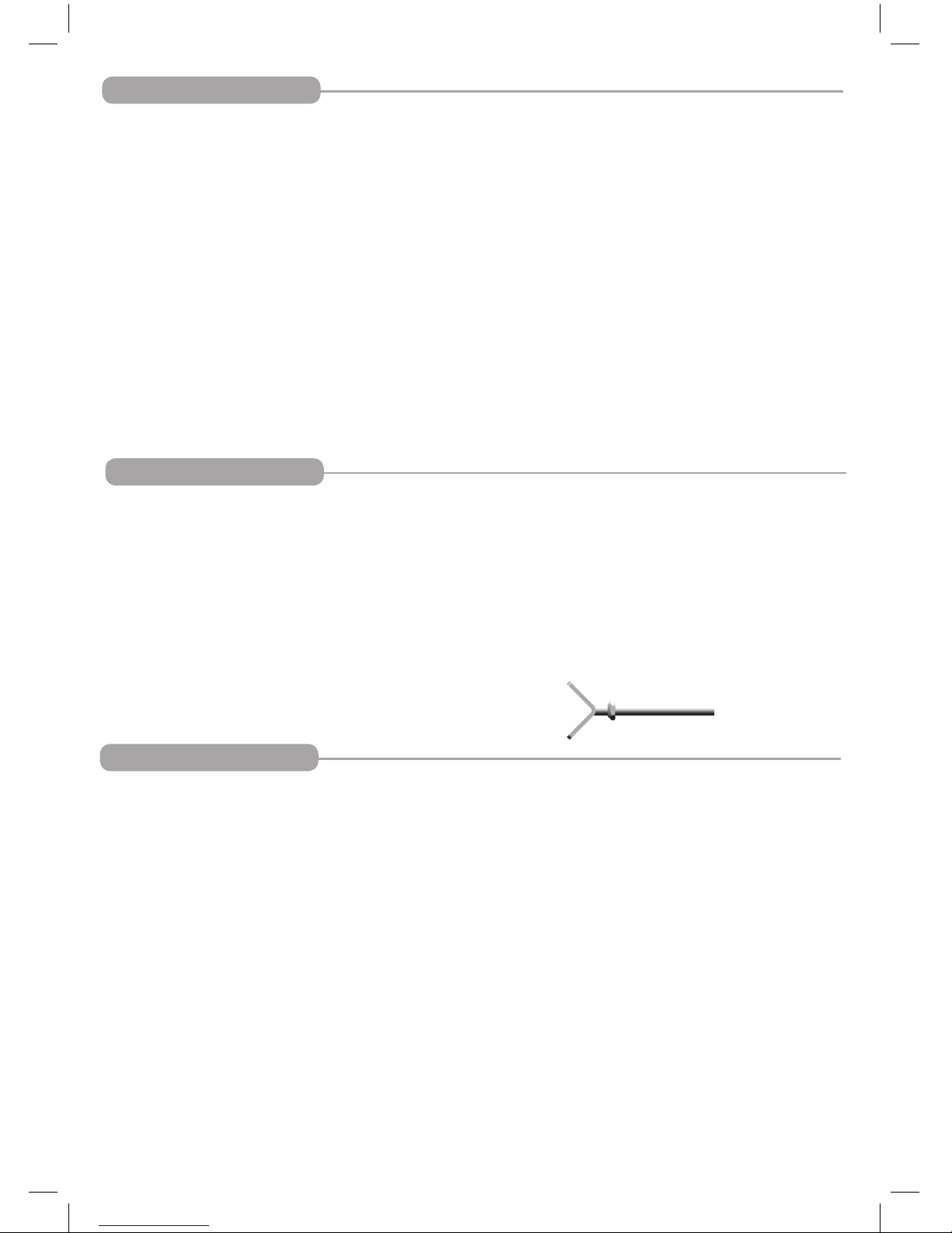
11. Installation aid
KidCo has available OPTIONAL Y spindles (Model GY-1
Spindle) to assist in installation when the
mounting surface has a round baluster. These spindles
are used in place of the spindles included with the basic
gate. They may be ordered through your local KidCo
dealer or direct from KidCo.
No more than 2 Y spindles may be used per gate
and both must be used on the same side.

Remarques importantes
Entretien
ATTENTION
LIRE ATTENTIVEMENT CES
INSTRUCTIONS ET
LES CONSERVER
POUR POUVOIR
S’Y RÉFÉRER
ULTÉRIEUREMENT.
Cette barrière a été conçue pour les enfants âgés
de 6 à 24 mois. Cependant, chaque enfant ayant un
rythme de croissance qui lui est propre, ces paramètres
doivent être adaptés en fonction du développement de
l’enfant.
Quand elle est installée selon les instructions entre
deux surfaces propres et solidement charpentées, la
barrière est conforme aux normes suivantes :
ASTM F-1004-07 United States Standards
EN 1930:2000 Normes européennes
• Utilisation prévue: enfants âgés de 6 à 24 mois.
• Vérifier la stabilité de la barrière et resserrer
régulièrement toute la quincaillerie et les supports.
• Pour écarter tout risque de blessure grave, voire
mortelle, installer solidement la barrière ou la
fermeture et utiliser conformément aux instructions
du fabricant.
• Ne jamais utiliser pour un enfant capable de
grimper par-dessus la barrière ou la fermeture
ou de la retirer.
• Ne jamais utiliser si la barrière ne mesure pas au
moins les trois quarts de la taille de l’enfant.
• Ne pas utiliser si une pièce de la barrière est cassée
ou manquante.
• Ce produit n’empêchera pas nécessairement tous
les accidents. Ne jamais laisser un enfant sans
surveillance.
• Utiliser uniquement des pièces détachées KidCo.
• Ne jamais laisser un enfant grimper sur la barrière ni
la secouer.
• Utiliser uniquement avec le mécanisme de
verrouillage/blocage solidement enclenché.
• Ne jamais utiliser la barrière en haut d’un escalier.
• Cesser l’utilisation si un composant quelconque de
la barrière est endommagé.
• Ne jamais grimper sur la barrière.
• Ne jamais suspendre ni attacher de jouets, etc. sur
une partie quelconque de la barrière.
• Aucune partie de la barrière n’exige de lubrification.
• Nettoyer à l’aide d’une éponge avec de l’eau
chaude et un détergent doux.
• Ne pas utiliser de nettoyants abrasifs ou un agent
blanchissant.
• Dans le cas d’une utilisation extérieure et pour
empêcher la formation de rouille, traiter la barrière
avec un antirouille. L’apparition de rouille est
toujours possible.
FRE
7
 Loading...