

Page 1

Owner’s Manual
KMTC
Marine Tower System
Owner’s Manual
KMTC9 | KMTC11
Manual del Propietario | Español
Gabinete de torre KICKER MARINE
Benutzerhandbuch | Deutsch
KICKER MARINE Can-Gehäuse
Manuel d’utilisation | Française
Boîtiers pour haut-parleurs verticaux
KICKER MARINE
Page 2

KICKER Marine Tower Systems
Owner’s Manual
MODEL: KMTC9 | KMTC11
Authorized KICKER Dealer:
Purchase Date:
Serial Number:
The KICKER KMTC Marine Tower Systems are the perfect way to bring your music out into the marine or
power sports environment. The KMTC9 and KMTC11 come loaded with KICKER KM LED speakers. The
injection-molded ABS enclosures are UV treated, splash resistant, and weather resilient. Mount the KMTC
Marine Tower Systems in your boat or get creative with a pair of them in the garage, on your 4x4 or Side-bySide’s roll bars, or in any other bar-mounted application.
Model: KMTC9 KMTC11
Woofer [in, cm] 9, 23 11, 28
Horn Loaded Compression Driver [in,mm] 1, 25 1, 25
Compression Driver Voice Coil Diameter [in,mm] 1-3/8, 35 1-3/8, 35
Dome Material Titanium Titanium
Rated Impedance [Ω] 4 4
Sensitivity [1W, 1m] 92 dB 93 dB
Frequency Response [Hz] 20-20,000 20-20,000
Peak Power Handling [ Watts] 600 600
Recommended Amplifi er Power [Watts RMS] 150–300 150–300
Enclosure Diameter/Width [in, cm] 9-13/16, 24.9 11-7/8, 30.2
Enclosure Depth [in, cm] 10-7/8, 27.7 12-11/16, 32.3
Enclosure Height (from bottom of roll bar) [in, cm] 11-9/16, 29.4 13-5/8, 34.6
Enclosure Height (bracket top to enclosure bottom) [in, cm] 13-9/16, 34.4 15-9/16, 39.6
High Pass [dB], at Frequency [Hz] 12db/oct, 2,500 Hz 12db/oct, 2,500 Hz
INSTALLATION
IMPORTANT: You must apply a thin layer of the included anti-seize compound to ALL threaded fasteners
before installation.
Before you begin: Determine the location and placement of the KMTC Marine Tower System onto the
pipe or tube to which you are mounting. Spreading the KMTC Marine Tower System apart will provide better
stereo performance, and is usually preferable. When determining the best locations for mounting, be careful
to look for obstacles or obstructions that could complicate mounting the KMTC. Please keep in mind the
routing of your speaker wires as this can affect where you fi nally mount your cans. If routing speaker wire
through tubing, drill a 9/16” size hole in the bar for a wire grommet before mounting.
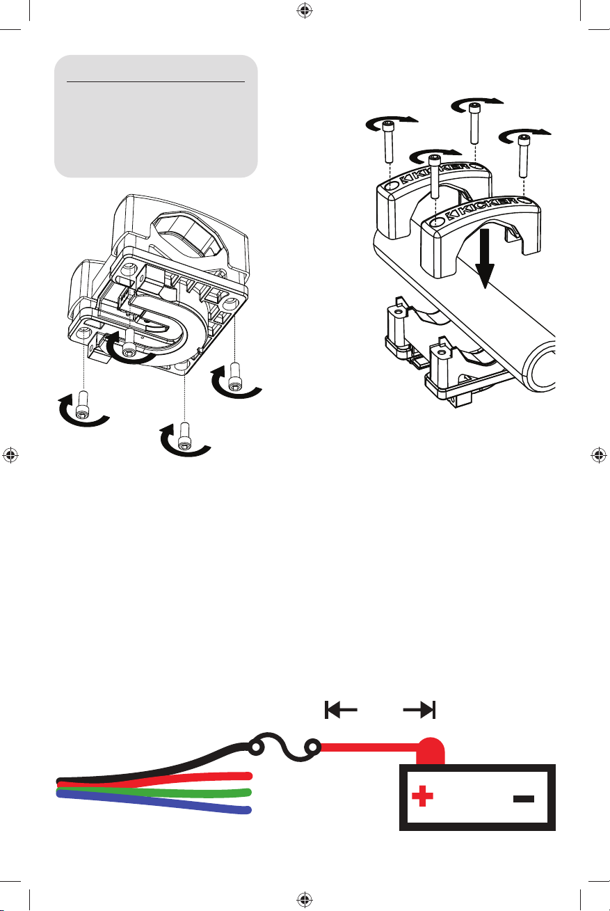
Step 1: Position the KMTC lower mounting brackets around the pipe or tubing to which you will be
mounting, then use the included socket-head screws to secure the upper mounting brackets to the bracket
assembly (Fig. 1). Use the screw size best suited for your application. Make sure the bottom bolts (Fig. 2 1-1/2” in length) are tight. Kicker recommends adding medium strength (blue) thread locker to these bottom
bolts before installation to prevent them from backing out over time.
2
Page 3
Bar Diameter Bolt Length
1-1/2” to <1-3/4” 1-1/8”
1-3/4” to 2-1/4” 1-1/2”
<2-1/4” to <2-7/8” 2”
2-7/8” to <3”
3” to 3-1/8” 3”
Figure 2
2-1/2”
stainless steel socket-head cap screws
(1/4” Allen wrench – 5/16”-18 threads)
Figure 1
upper mounting
bracket
lower mounting
bracket
Step 2: Connect the speaker and tweeter wires to your source unit or amplifi er. KICKER recommends you
solder the connections and secure them with heat shrink. It is also strongly recommended that you use a
full-range amplifi er signal. A high-pass crossover set from 30Hz–50Hz should be used, and can be set to
70Hz for music with heavy bass.
When hard-wiring the RGB lighting, the black lead is +12V and the red, green, and blue leads are ground.
Splice and combine the ground wires to yield a different color. There are seven colors available, depending
on your wiring confi guration. KICKER recommends using the KMLC lighting controller (sold separately) for
more colors, patterns, and special effects.
Black : +12V Red : Ground Green : Ground Blue : Ground
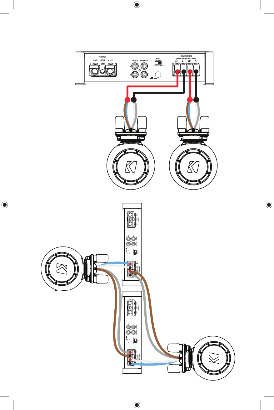
Transparent Blue : Speaker + Transparent Gray : Speaker –
Copper : Horn Tweeter + Silver : Horn Tweeter –
LED Wiring
+12V
2A fuse
}
(max)
Ground
≤7”
(17.5cm)
12V
battery
3
Page 4
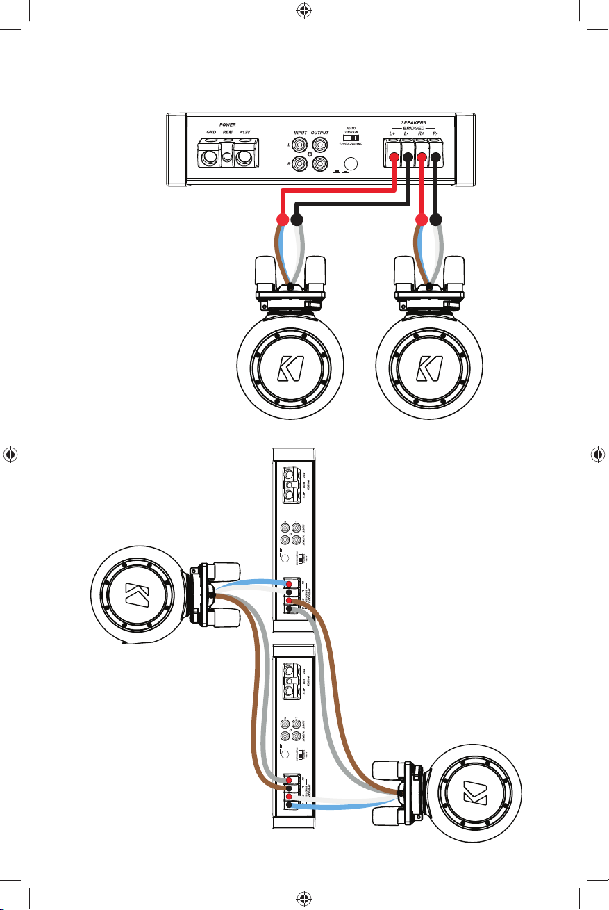
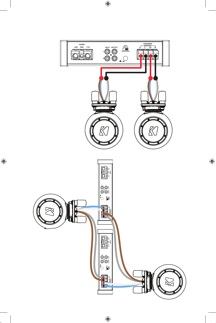
STEREO OPERATION
4 ohms
Though wired in parallel, the passive crossover results in a fi nal impedance of 4 Ω.
KXMA1200.2
BI-AMP
4 ohms
RADIO
DETECT
OFF/ON/
KXMA1200.2
DETECT
RADIO
OFF/ON/
DETECT
RADIO
OFF/ON/
4
Page 5
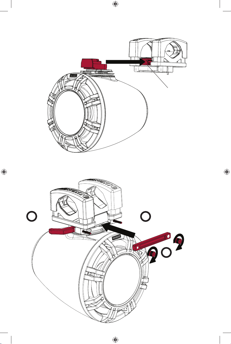
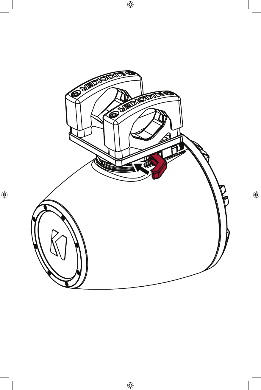
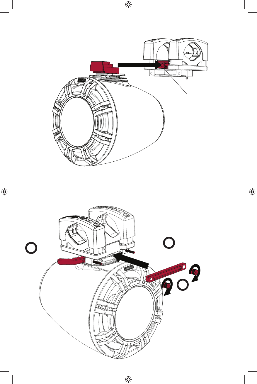
Step 3: Install the keyed connector of the KMTC speaker’s swivel assembly into the keyed socket of the
bracket assembly. The front of the keyed connector should be fl ush with the keyed socket.
keyed connector
keyed socket
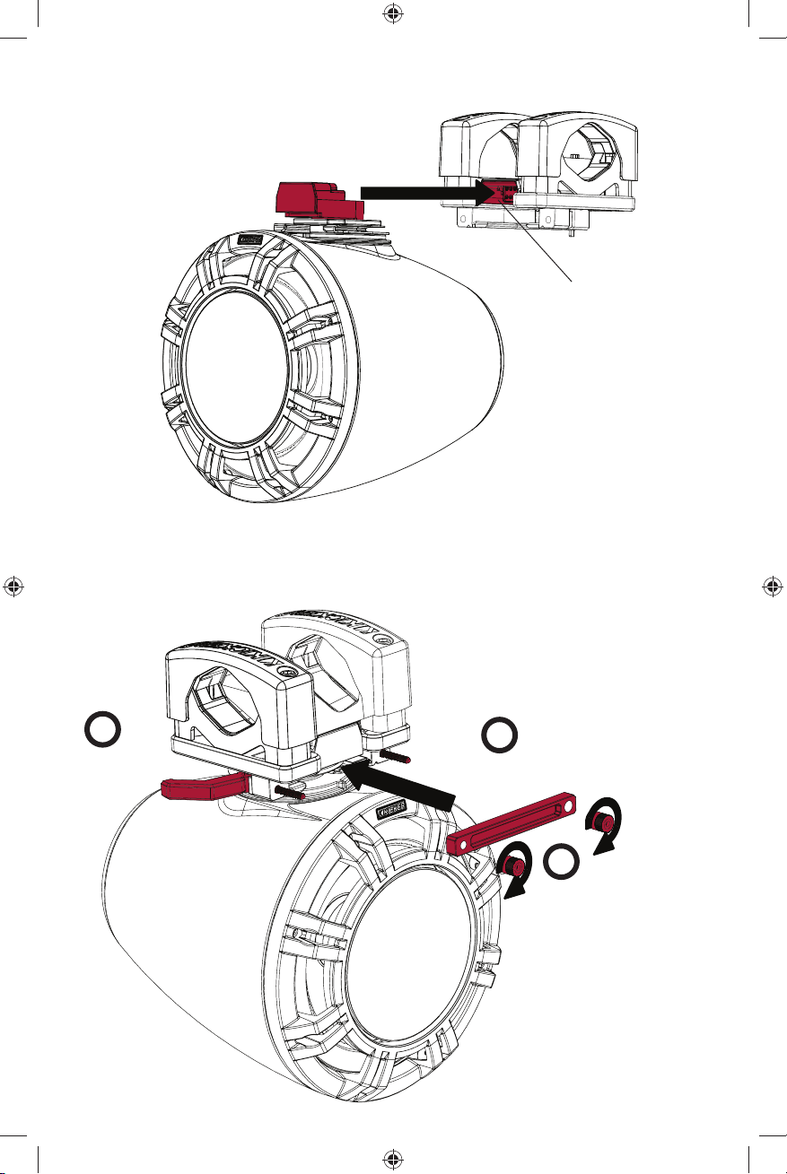
Step 4: Install the two swivel levers, adjusting them to be loose (open) when the lever is parallel to the tube,
then secure the bracket gate to the enclosure using the included thumb nuts. When the swivel levers are
locked in place, or closed, the bracket rotation assembly will be clamped tight. With the swivel levers open,
fi nish by tightly securing both thumb nuts. You may need to retighten one after tightening the other.
1
swivel lever
5
2
bracket gate
3
thumb nuts
To mount the enclosure
without swivel adjustment, use
the included socket-head cap
screws to secure the bracket
gate instead of the swivel
levers.
Page 6
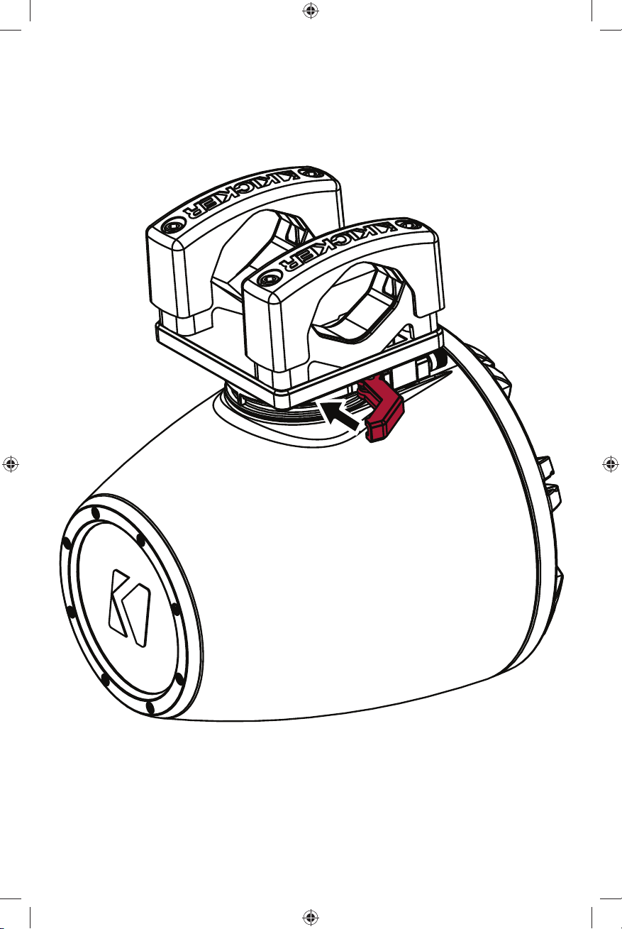
Step 5: Ensure the enclosure is secure by increasing the tension of the swivel lever thumb nuts attached
to the swivel levers. When the swivel levers are closed, the KMTC Marine Tower System should be locked
in place. When open, you may adjust the orientation by swiveling the assembly left or right. When you are
satisfi ed with the orientation, close the swivel levers to lock the enclosure in place. If the enclosure is not
locked tightly enough, tighten the thumb nuts.
6
Page 7

Manual del propietario de los
Sistemas de Torre Marina de KICKER
MODELO: KMTC9 | KMTC11
Distribuidor autorizado KICKER:
Fecha de compra:
Número de Serie:
Los Sistemas de Torre Marina KMTC de Kicker son el modo perfecto de llevar su música a la marina
o potenciar los entornos deportivos. Los sistemas KMTC9 y KMTC11 están equipados con altavoces
KICKER KM LED. Las carcasas ABS moldeadas por inyección están tratadas con UV y son resistentes
a las salpicaduras y a los fenómenos meteorológicos. Instale los Sistemas de Torre Marina KMTC en su
embarcación o dé rienda suelta a su creatividad colocándolos en su cochera, en las barras antivuelco de su
vehículo 4x4 o Side by Side, o montándolos en cualquier otro tipo de barras.
Modelo: KMTC9 KMTC11
Woofer [pulgadas, cm] 9, 23 11, 28
Controlador de compresor de bocina cargado [pulgadas,mm] 1, 25 1, 25
Diámetro de la bobina de voz del
controlador de compresor [pulgadas,mm] 1-3/8, 35 1-3/8, 35
Material del domo Titanio Titanio
Impedancia nominal [Ω] 4 4
Sensibilidad [1 V, 1m] 92 dB 93 dB
Frecuencia de respuesta [Hz] 20-20,000 20-20,000
Máximo manejo de potencia [Vatios] 600 600
Manejo de potencia recomendado [Vatios RMS] 150–300 150–300
Diámetro/ancho de la carcasa [pulgadas, cm] 9-13/16, 24.9 11-7/8, 30.2
Profundidad de la carcasa [pulgadas, cm] 10-7/8, 27.7 12-11/16, 32.3
Altura de la carcasa (desde la parte inferior
hasta la barra antivuelco) [pulgadas, cm] 11-9/16, 29.4 13-5/8, 34.6
Altura de la carcasa (parte superior del soporte
hasta la parte inferior de la carcasa) [pulgadas, cm] 13-9/16, 34.4 15-9/16, 39.6
Paso alto [dB], a una frecuencia de [Hz] 12db/oct, 2,500 Hz 12db/oct, 2,500 Hz
INSTALACIÓN
IMPORTANTE: debe aplicar una capa delgada del compuesto antiagarrotante proporcionado a TODOS los
tornillos comprometidos antes de la instalación.
Antes de comenzar: determine la ubicación y colocación del Sistema de Torre Marina KMTC en el tubo o
caño en el que lo instalará. La separación del Sistema de Torre Marina KMTC ofrecerá un mejor rendimiento
del estéreo, y generalmente resulta preferible. Al determinar los mejores lugares para la instalación, tenga
cuidado de notar cualquier obstáculo u obstrucción que pudiera complicar la instalación del KMTC.
Tenga en cuenta el recorrido de los cables del altavoz, ya que pueden infl uir en el lugar donde fi nalmente
instalará los altavoces. Si traza el recorrido del cable del altavoz de modo que atraviese el caño, realice una
perforación de 9/16” en la barra para colocar un pasacables antes de realizar el montaje.
Paso 1: coloque los soportes de montaje inferiores KMTC alrededor del tubo o caño en el que los montará;
luego utilice los tornillos de cabeza hueca proporcionados para asegurar los soportes de montaje superiores
al ensamble del soporte. Utilice el tamaño de tornillo que se adapte mejor a sus necesidades. Ver Fig. 1.
7
Page 8
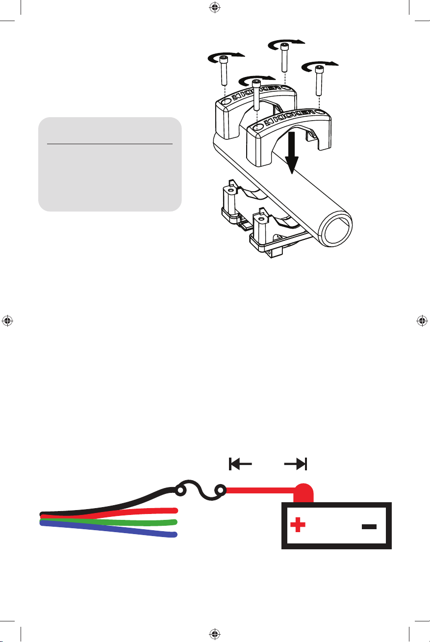
Fig. 1
tornillos de cabeza hueca de acero inoxidable
(1/4” llave Allen – 5/16”-18 roscas)
Diámetro de Longitud del
la barra perno
1-1/2” to <1-3/4” 1-1/8”
1-3/4” to 2-1/4” 1-1/2”
<2-1/4” to <2-7/8” 2”
2-7/8” to <3” 2-1/2”
3” to 3-1/8” 3”
soporte de
montaje inferior
Paso 2: conecte los cables del altavoz y del tweeter a su unidad fuente o amplifi cador. KICKER le
recomienda soldar las conexiones y asegurarlas con termorretracción.
Al realizar la instalación eléctrica permanente de la iluminación RGB, el cable negro es +12 V, y los cables
rojo, verde y azul son a tierra. Empalme y combine los cables a tierra para producir un color diferente. Hay
siete colores disponibles, según su confi guración del cableado. KICKER le recomienda utilizar el controlador
de iluminación KMLC (se vende por separado) para obtener más colores, patrones y efectos especiales.
soporte de
montaje superior
Negro : +12 V Rojo : a tierra Verde : a tierra Azul : a tierra
Azul transparente: Altavoz + Gris transparente : Altavoz –
Cobre: Bocina tweeter + Plateado: Bocina tweeter –
LED Wiring
+12V
fusible
(max)
Conexión
}
a tierra
2A
≤7”
(17.5cm)
12V
batería
8
Page 9
FUNCIONAMIENTO ESTÉREO
4 ohmios
Aunque está conectado en paralelo, el cruce pasivo da como resultado una impedancia fi nal de 4Ω.
KXMA1200.2
BI-AMP
4 ohmios
RADIO
DETECT
OFF/ON/
KXMA1200.2
DETECT
RADIO
OFF/ON/
DETECT
RADIO
OFF/ON/
9
Page 10

Paso 3: instale el conector enchavetado del ensamblaje articulado del altavoz KMTC en el conector
hembra enchavetado del ensamble del soporte. El frente del conector enchavetado debe empotrarse en el
conector hembra enchavetado.
conector
enchavetado
conector femenino
enchavetado
Paso 4: instale las dos palancas giratorias y regúlelas de modo que queden fl ojas (abiertas) cuando la
palanca esté paralela al tubo. Luego asegure la compuerta del soporte a la carcasa utilizando las tuercas
manuales proporcionadas. Cuando las palancas giratorias estén fi jadas en su lugar, o cerradas, el
ensamblaje rotatorio del soporte quedará sujeto fi rmemente. Con las palancas giratorias abiertas, fi nalice
asegurando fi rmemente ambas tuercas manuales. Es posible que deba volver a ajustar una luego de ajustar
la otra.
1
palanca
giratoria
10
2
compuerta del soporte
3
tuercas manuales
Para montar la carcasa
sin un ajuste articulado,
utilice los tornillos Allen
proporcionados para
asegurar la compuerta del
soporte en lugar de las
palancas giratorias.
Page 11
Paso 5: asegúrese de que la carcasa esté asegurada aumentando la tensión de las tuercas manuales
de la palanca giratoria sujetas a las palancas giratorias. Cuando las palancas giratorias estén cerradas, el
Sistema de Torre Marina KMTC quedará fi jo en su lugar. Cuando estén abiertas, podrá regular la orientación
rotando el ensamblaje hacia la izquierda o derecha. Cuando esté conforme con la orientación, cierre las
palancas giratorias para fi jar la carcasa en su lugar. Si la carcasa no está fi jada de manera sufi cientemente
fi rme, ajuste las tuercas manuales.
11
Page 12

Systèmes pour tour aquatique KICKER
Manuel de l’utilisateur
MODÈLE : KMTC9 | KMTC11
Distributeur KICKER agréé :
Date d’achat :
Numéro de série :
Les systèmes pour tour aquatique KMTC de KICKER sont les solutions idéales pour emmener votre
musique dans les environnements de sports aquatiques et de sports motorisés. Les modèles KMTC9 et
KMTC11 sont équipés de haut-parleurs LED KM de KICKER. Les boîtiers ABS moulés par injection sont
anti-UV, résistants aux éclaboussures et aux conditions climatiques diffi ciles. Installez les systèmes pour
tour aquatique KMTC sur votre bateau, ou soyez créatif en installant une paire dans votre garage, sur
votre 4x4 ou sur les arceaux de votre SSV, ou tout autre installation à arceaux.
Modèle : KMTC9 KMTC11
Haut-parleur de graves [pouces, cm] 9, 23 11, 28
Moteur de compression à pavillon [pouces, mm] 1, 25 1, 25
Diamètre de la bobine acoustique du
moteur de compression [pouces, mm] 1-3/8, 35 1-3/8, 35
Matériau de la coupole Titane Titane
Impédance nominale [Ω] 4 4
Sensibilité [1 W, 1 m] 92 dB 93 dB
Réponse en fréquence [Hz] 20-20,000 20-20,000
Puissance maximale [Watts] 600 600
Recommandée Manipulation de puissance [Watts RMS] 150–300 150–300
Diamètre/largeur du boîtier [pouces, cm] 9-13/16, 24,9 11-7/8, 30,2
Profondeur du boîtier [pouces, cm] 10-7/8, 27,7 12-11/16, 32,3
Hauteur du boîtier (depuis le bas
de l’arceau) [pouces, cm] 11-9/16, 29.4 13-5/8, 34.6
Hauteur du boîtier (du haut du support
au bas du boîtier) [pouces, cm] 13-9/16, 34,4 15-9/16, 39,6
Filtre passe-haut [dB], à fréquence [Hz] 12 db/oct., 2 500 12 db/oct., 2 500
INSTALLATION
IMPORTANT : ll est impératif d’appliquer une mince couche du composé antigrippant fourni sur TOUTES
les fi xations fi letées avant toute installation.
Avant de commencer : choisissez l’emplacement et la position du système pour tour aquatique KMTC
(Marine Tower System) sur le tuyau ou arceau sur lequel vous souhaitez l’installer. La répartition des élément
du système KMTC (Marine Tower System) permettra d’obtenir de meilleures performances acoustiques, et
c’est généralement ce qui est recommandé. Pour trouver les meilleurs endroits où installer votre système,
assurez-vous qu’il n’y ait pas d’obstacles qui pourrait gêner l’installation du KMTC. Pensez au cheminement
de vos câbles de haut-parleur car cela peut affecter leur emplacement fi nal. Si vous choisissez de faire
passer les câbles à travers un tuyau, percez un trou de diamètre 9/16 de pouces dans la barre en prévision
d’un passe-câble avant de commencer l’installation.
Étape 1 : positionnez les supports de montage inférieurs du KMTC autour du tube ou de l’arceau sur
lequel il sera installé, et utilisez les vis à tête creuse fournies pour fi xer les supports de montage supérieurs à
l’ensemble support. Utilisez la taille de vis la plus appropriée à votre installation. Voir Fig. 1.
12
Page 13

vis à tête creuse en acier inoxydable
(clé Allen 1/4” – fi letage 5/16”-18)
dimensions en pouces
Diamètre longueur
de la barre du boulon
1-1/2” to <1-3/4” 1-1/8”
1-3/4” to 2-1/4” 1-1/2”
<2-1/4” to <2-7/8” 2”
2-7/8” to <3” 2-1/2”
3” to 3-1/8” 3”
support de fi xation
inférieur
Étape 2 : branchez les fi ls du haut-parleur et du tweeter à votre ampli ou à votre source principale. KICKER
recommande de souder les connexions et de les sécuriser à l’aide d’une gaine thermorétractable.
Fig. 1
support de fi xation
supérieur
Lorsque vous connectez votre éclairage RVB, le fi l noir est à +12 V et les fi ls rouge, vert et bleu sont mis
à la terre. Épissez et combinez les fi ls de la terre pour obtenir une couleur différente. Sept couleurs sont
disponibles, en fonction de la confi guration de votre câblage. KICKER recommande d’utiliser le régulateur
d’éclairage KMLC (vendu séparément) pour obtenir plus de couleurs, de motifs et d’effets spéciaux.
Noir : +12 V Rouge : terre Vert : terre Bleu : terre
Bleu transparent : haut-parleur + Gris transparent : haut-parleur –
Cuivre : tweeter pavillon + Argent : tweeter pavillon –
2A fuse
(max)
≤7”
(17,5cm)
+12V
Prise
de terre
}
12V
batteríe
13
Page 14

FONCTIONNEMENT STÉRÉO
4 ohms
Bien que câblé en parallèle, le crossover passif se traduit par une impédance fi nale de 4 Ω.
KXMA1200.2
BI-AMP
4 ohms
RADIO
DETECT
OFF/ON/
KXMA1200.2
DETECT
RADIO
OFF/ON/
DETECT
RADIO
OFF/ON/
14
Page 15
Étape 3 : installez le connecteur à clavette de l’assemblage pivotant de l’enceinte KMTC dans la douille à
clavette de l’ensemble articulé. L’avant du connecteur à clavette doit être aligné avec la douille.
connecteur à clavette
douille à clavette
Étape 4 : installez les deux leviers pivotants, desserrez-les (ouvert) lorsqu’ils sont parallèles au tuyau, et fi xez
la grille de support au boîtier à l’aide des écrous papillon fournis. Lorsque les leviers pivotants sont bien en
place, ou fermés, le support de l’ensemble pivotant sera fermement serré. Tout en maintenant les leviers
ouverts, terminez en fi xant fermement les deux écrous papillon. Vous devrez peut-être resserrer l’un après
avoir serré l’autre.
levier
pivotant
15
1
2
grille de support
3
écrous papillon
Pour installer le boîtier sans
réglage de pivotement, utilisez
les vis à tête creuse fournies
pour fi xer la grille du support à
la place des leviers pivotants.
Page 16

Étape 5 : assurez-vous que le boîtier soit fermement fi xé en augmentant la tension des écrous à bille du
levier pivotant fi xés aux leviers de pivotement. Lorsque les leviers pivotants sont fermés, le système KMTC
(Marine Tower System) devrait être correctement verrouillé. Lorsqu’ils sont ouverts, vous pouvez modifi er
l’orientation en faisant pivoter l’ensemble vers la gauche ou la droite. Si vous êtes satisfait de l’orientation,
fermez les leviers pour verrouiller le boîtier en place. Si le boîtier n’est pas suffi samment fi xé, resserrez les
écrous papillon.
16
Page 17

KICKER Marine Tower Systeme
Bedienungsanleitung
MODELL: KMTC9 | KMTC11
Autorisierter KICKER-Händler:
Kaufdatum:
Seriennummer:
Die KICKER KMTC Marine Tower Systeme sind die perfekte Lösung, wenn Sie Ihre Musik auf dem
Wasser oder beim Motorsport genießen möchten. Die Systeme KMTC9 und KMTC11 sind mit den
KICKER KM LED-Lautsprechern bestückt. Die spritzgegossenen ABS-Gehäuse sind UV-beständig,
spritzwassergeschützt und witterungsbeständig. Nuztzen Sie die KMTC Marine Tower Systeme auf Ihrem
Boot oder in Ihrer Garage. Lassen sie Ihrer Kreativität dabei freien Lauf. Sie können die Systeme in Ihrem
Allradfahrzeug, auf Überrollbügeln oder überall dort anbringen, wo sie an Stangen montiert werden können.
Modell: KMTC9 KMTC11
Tieftöner [Zoll, cm] 9, 23 11, 28
Horn + Druckkammertreiber [Zoll, mm] 1, 25 1, 25
Druckkammertreiber Schwingspule
Durchmesser [Zoll, mm] 1-3/8, 35 1-3/8, 35
Dom-Material Titan Titan
Nennimpedanz [Ω] 4 4
Empfi ndlichkeit [1 W, 1 m] 92 dB 93 dB
Frequenzgang [Hz] 20-20.000 20-20.000
Spitzenbelastbarkeit [Watt] 600 600
Empfohlene Verstärkerleistung [Watt RMS] 150–300 150–300
Gehäusedurchmesser/-breite [Zoll, cm] 9-13/16, 24,9 11-7/8, 30,2
Gehäusetiefe [Zoll, cm] 10-7/8, 27,7 12-11/16, 32,3
Gehäusehöhe (von der Unterseite
des Überrollbügels) [Zoll, cm] 11-9/16, 29,4 13-5/8, 34,6
Gehäusehöhe (Von der Oberseite der
Halterung bis zum Gehäuseboden) [Zoll, cm] 13-9/16, 34,4 15-9/16, 39,6
Hochpass [dB], bei Frequenz [Hz] 12 db/oct, 2.500 12 db/oct, 2.500
INSTALLATION
WICHTIG: Sie müssen vor der Installation eine dünne Schicht des mitgelieferten Schutzmittels auf ALLE
Befestigungselemente mit Gewinde auftragen.
Bevor Sie beginnen: Bestimmen Sie die Position an der Stange oder dem Rohr, wo das KMTC Marine Tower
System befestigt werden soll. Sie sollten die KMTC Marine Tower Systeme vorzugsweise weiter auseinander
platzieren, damit die Stereowiedergabe besser zur Geltung kommt. Achten Sie bei der Montageposition
auf Hindernisse, die die Installation des KMTC-Systems erschweren könnten. Bitte beachten Sie auf die
Verlegung Ihrer Lautsprecherkabel, da dies die Platzierung Ihrer Boxen beeinfl ussen kann. Wenn Sie das
Lautsprecherkabel durch ein Rohr führen, bohren Sie vor der Montage ein 9/16 Zoll großes Loch in die
Schiene für eine Kabeldurchführung.
Schritt 1: Positionieren Sie die unteren KMTC-Montagehalterungen um das Rohr oder die Stange, wo
sie befestigt werden sollen und befestigen Sie dann die oberen Montagehalterungen mit den mitgelieferten
Inbusschrauben an der Halterungsbaugruppe. Verwenden Sie die für Ihre Anwendung am besten geeignete
Schraubengröße. Siehe Abb. 1.
17
Page 18

Edelstahl-Zylinderschrauben (1/4 ZollInbusschlüssel - 5/16 Zoll-18-Gewinde)
Maße in zoll
Abb. 1
Rohrdurch- Schraub-
messer enlänge
1-1/2” to <1-3/4” 1-1/8”
1-3/4” to 2-1/4” 1-1/2”
<2-1/4” to <2-7/8” 2”
2-7/8” to <3” 2-1/2”
3” to 3-1/8” 3”
untere Halterung
Schritt 2: Verbinden Sie den Lautsprecher und die Hochtöner mit Ihrem Quellgerät oder Verstärker.
KICKER empfi ehlt, die Anschlüsse zu löten und mit einem Schrumpfschlauch zu sichern.
Wenn die RGB-Beleuchtung fest verkabelt wird, ist das schwarze Kabel +12 V und sind die roten, grünen
und blauen Kabel geerdet. Spleißen und kombinieren Sie die Erdungsdrähte, um eine andere Farbe zu
erhalten. Abhängig von Ihrer Verdrahtungskonfi guration sind sieben Farben verfügbar. KICKER empfi ehlt
die Verwendung des KMLC-Beleuchtungscontrollers (separat erhältlich) für mehr Farben, Muster und
Spezialeffekte.
obere Halterung
Schwarz: +12 V Rot: Erdung Grün: Erdung Blau: Erdung
Transparentes Blau: Lautsprecher + Transparentes Grau: Lautsprecher –
Kupfer: Hornhochtöner, + Silber: Hornhochtöner –
2A
Sicherung
(max)
≤7”
(17,5cm)
+12V
Erdung
}
12V
batteríe
18
Page 19
STEREO-BETRIEB
4 ohms
Obwohl parallel verdrahtet, führt die passive Frequenzweiche zu einer Endimpedanz von 4 Ω.
KXMA1200.2
BI-AMP
4 ohms
RADIO
DETECT
OFF/ON/
KXMA1200.2
DETECT
RADIO
OFF/ON/
DETECT
RADIO
OFF/ON/
19
Page 20
Schritt 3: Stecken Sie den kodierten Steckverbinder der Schwenkvorrichtung des KMTC-Lautsprechers in
die kodierte Buchse der Halterungsbaugruppe. Die Vorderseite des kodierten Steckverbinders sollte bündig
mit der kodierten Buchse abschließen.
kodierter Steckverbinder
kodierte Buchse
Schritt 4: Montieren Sie die zwei Schwenkhebel und stellen Sie sie so ein, dass sie lose (offen) sind, wenn
der Hebel parallel zum Rohr steht und befestigen Sie dann die Halterung mit den mitgelieferten Flügelmuttern
am Gehäuse. Wenn die Schwenkhebel arretiert oder geschlossen werden, ist die Halterungsdrehbaugruppe
festgeklemmt. Bei geöffneten Schwenkhebeln drehen Sie beide Flügelmuttern fest. Möglicherweise müssen
Sie nach dem Anziehen von einer Flügelmutter, die andere wieder festziehen.
1
Schwenkhebel
20
2
Halterung
3
Flügelmuttern
Zur Montage des Gehäuses ohne
Schwenkeinstellung verwenden
Sie die im Lieferumfang
enthaltenen Inbusschrauben,
um die Halterung anstelle der
Schwenkhebel zu befestigen.
Page 21

Schritt 5: Stellen Sie sicher, dass das Gehäuse fi xiert ist, indem Sie die Spannung der an den
Schwenkhebeln angebrachten Schwenkhebel-Flügelmuttern erhöhen. Wenn die Schwenkhebel
geschlossen sind, sollte das KMTC Marine Tower System eingerastet sein. Im geöffneten Zustand können
Sie die Ausrichtung anpassen, indem Sie die Baugruppe nach links oder rechts schwenken. Wenn Sie mit
der Ausrichtung zufrieden sind, schließen Sie die Schwenkhebel, um das Gehäuse zu arretieren. Wenn das
Gehäuse nicht fest genug verschlossen ist, ziehen Sie die Flügelmuttern fest.
21
Page 22

ACOUSTICS LIMITED WARRANTY
When purchased from an Authorized KICKER Dealer, KICKER warrants this product to be free from defects in material
and workmanship under normal use for a period of ONE (1) YEAR from date of original purchase. If this product is
identifi ed as “Refurbished” or “B Goods”, the warranty is limited to a period of THREE (3) MONTHS from date of original
purchase. In all cases you must have the original receipt. Should service be necessary under this warranty for any reason
due to manufacturing defect or malfunction during the warranty period, KICKER will repair or replace (at its discretion)
the defective merchandise with equivalent merchandise. Warranty replacements may have cosmetic scratches and
blemishes. Discontinued products may be replaced with more current equivalent products. This warranty is valid only for
the original purchaser and is not extended to owners of the product subsequent to the original purchaser. Any applicable
implied warranties are limited in duration to a period of the express warranty as provided herein beginning with the date of
the original purchase at retail, and no warranties, whether express or implied, shall apply to this product thereafter. Some
states do not allow limitations on implied warranties; therefore, these exclusions may not apply to you. This warranty
gives you specifi c legal rights; however you may have other rights that vary from state to state.
WHAT TO DO IF YOU NEED WARRANTY OR SERVICE:
Defective merchandise should be returned to your local Authorized Stillwater Designs (KICKER) Dealer for warranty
service. Assistance in locating an Authorized Dealer can be found at www.kicker.com or by contacting Stillwater Designs
directly. You can confi rm that a dealer is authorized by asking to see a current authorized dealer window decal.
If it becomes necessary for you to return defective merchandise directly to Stillwater Designs (KICKER), call the KICKER
Customer Service Department at (405) 624-8510 for a Return Merchandise Authorization (RMA) number. Package only
the defective items in a package that will prevent shipping damage, and return to:
Stillwater Designs, 3100 North Husband St, Stillwater, OK 74075
The RMA number must be clearly marked on the outside of the package. Please return only defective component
systems. The return of functioning items increases your return freight charges. Non-defective items will be returned
freightcollect to you. For example, if a subwoofer is defective, only return the defective subwoofer, not the entire
enclosure. Include a copy of the original receipt with the purchase date clearly visible, and a “proof-of-purchase”
statement listing the Customer’s name, Dealer’s name and invoice number, and product purchased. Warranty expiration
on items without proof-of-purchase will be determined from the type of sale and manufacturing date code. Freight must
be prepaid; items sent freight-collect, or COD, will be refused.
WHAT IS NOT COVERED?
This warranty is valid only if the product is used for the purpose for which it was designed. It does not cover:
o Damage due to improper installation
o Subsequent damage to other components
o Damage caused by exposure to excessive heat, chemical cleaners, and/or UV radiation
o Damage through negligence, misuse, accident or abuse. Repeated returns for the same damage may be
considered abuse
o Any cost or expense related to the removal or reinstallation of product
o Speakers damaged due to amplifi er clipping or distortion
o Items previously repaired or modifi ed by any unauthorized repair facility
o Return shipping on non-defective items
o Products with tampered or missing barcode labels
o Products with tampered or missing serial numbers
o Products returned without a Return Merchandise Authorization (RMA) number
o Products purchased from an UNAUTHORIZED dealer
o Freight Damage
o The cost of shipping product to KICKER
o Service performed by anyone other than KICKER
HOW LONG WILL IT TAKE?
KICKER strives to maintain a goal of one-week service for all acoustics (subwoofers, midrange drivers, tweeters,
crossovers, etc) returns. Delays may be incurred if lack of replacement inventory or parts is encountered. Failure to
follow these steps may void your warranty. Any questions can be directed to the KICKER Customer Service Department
at (405) 624-8510. Contact your International KICKER dealer or distributor concerning specifi c procedures for your
country’s warranty policies.
Note: All specifi cations and performance fi gures are subject to change. Please visit www.kicker.com for the most
current information.
P.O. Box 459 • Stillwater, Oklahoma 74076 • USA • (405) 624–8510
stillwaterdesigns
44KMTC9-11-J-20210118
22
Page 23

INTERNATIONAL WARRANTY
Contact your International KICKER dealer or distributor concerning specifi c procedures for your country’s warranty policies.
Our goods come with guarantees that cannot be excluded under the Australian Consumer Law. You are entitled to a
replacement or refund for a major failure and for compensation for any other reasonably foreseeable loss or damage. You
are also entitled to have the goods repaired or replaced if the goods fail to be of acceptable quality and the failure does
not amount to a major failure.
WARNING: KICKER products are capable of producing sound levels that can permanently damage your hearing! Turning up a
system to a level that has audible distortion is more damaging to your ears than listening to an undistorted system at the same
volume level. The threshold of pain is always an indicator that the sound level is too loud and may permanently damage your
hearing. Please use common sense when controlling volume.
GARANTÍA INTERNACIONAL Versión Español
Comuníquese con su concesionario o distribuidor KICKER internacional para obtener información sobre procedimientos
específi cos relacionados con las normas de garantía de su país.
ADVERTENCIA: Los excitadores KICKER son capaces de producir niveles de sonido que pueden dañar permanentemente
el oído. Subir el volumen del sistema hasta un nivel que produzca distorsión es más dañino para el oído que escuchar un
sistema sin distorsión al mismo volumen. El dolor es siempre una indicación de que el sonido es muy fuerte y que puede dañar
permanentemente el oído. Sea precavido cuando controle el volumen.
La frase “combustible para vivir la vida Livin’ Loud™ a todo volumen” se refi ere al entusiasmo por la vida que la marca KICKER
de estéreos de automóvil representa y a la recomendación a nuestros clientes de que vivan lo mejor posible (“a todo volumen”)
en todo sentido. La línea de altavoces y amplifi cadores KICKER es la mejor del mercado de audio de automóviles y por lo tanto
representa el “combustible” para vivir a todo volumen en el área de “estéreos de automóvil” de la vida de nuestros clientes.
Recomendamos a todos nuestros clientes que obedezcan todas las reglas y reglamentos locales sobre ruido en cuanto a los
niveles legales y apropiados de audición fuera del vehículo.
INTERNATIONALE GARANTIE Deutsche Version
Nehmen Sie mit Ihren internationalen KICKER-Fachhändler oder Vertrieb Kontakt auf, um Details über die Garantieleistungen in
Ihrem Land zu erfahren.
WARNUNG: KICKER-Treiber können einen Schallpegel erzeugen, der zu permanenten Gehörschäden führen kann! Wenn Sie ein
System auf einen Pegel stellen, der hörbare Verzerrungen erzeugt, schadet das Ihren Ohren mehr, als ein nicht verzerrtes System
auf dem gleichen Lautstärkepegel. Die Schmerzschwelle ist immer eine Anzeige dafür, dass der Schallpegel zu laut ist und zu
permanenten Gehörschäden führen kann. Seien Sie bei der Lautstärkeeinstellung bitte vernünftig!
Der Slogan “Treibstoff für Livin’ Loud” bezieht sich auf die mit den KICKER-Autostereosystemen assoziierte Lebensfreude und die
Tatsache, dass wir unsere Kunden ermutigen, in allen Aspekten ihres Lebens nach dem Besten (“Livin’ Loud”) zu streben. Die
Lautsprecher und Verstärker von KICKER sind auf dem Markt für Auto-Soundsysteme führend und stellen somit den “Treibstoff”
für das Autostereoerlebnis unserer Kunden dar. Wir empfehlen allen unseren Kunden, sich bezüglich der zugelassenen und
passenden Lautstärkepegel außerhalb des Autos an die örtlichen Lärmvorschriften zu halten.
GARANTIE INTERNATIONALE Version Française
Pour connaître les procédures propres à la politique de garantie de votre pays, contactez votre revendeur ou distributeur
International KICKER.
AVERTISSEMENT: Les haut-parleurs KICKER ont la capacité de produire des niveaux sonores pouvant endommager l’ouïe de
façon irréversible ! L’augmentation du volume d’un système jusqu’à un niveau présentant une distorsion audible endommage
davantage l’ouïe que l’écoute d’un système sans distorsion au même volume. Le seuil de la douleur est toujours le signe que le
niveau sonore est trop élevé et risque d’endommager l’ouïe de façon irréversible. Réglez le volume en faisant prevue de bon sens!
L’expression “ carburant pour vivre plein pot “ fait référence au dynamisme de la marque KICKER d’équipements audio pour
véhicules et a pour but d’encourager nos clients à faire le maximum (“ vivre plein pot “) dans tous les aspects de leur vie. Les
haut-parleurs et amplifi cateurs KICKER sont les meilleurs dans le domaine des équipements audio et représentent donc pour nos
client le “ carburant pour vivre plein pot “ dans l’aspect “ installation audio de véhicule “ de leur vie. Nous encourageons tous nos
clients à respecter toutes les lois et réglementations locales relatives aux niveaux sonores acceptables à l’extérieur des véhicules.
23
Page 24

©2017 Stillwater Designs
 Loading...