

Page 1

KMT60
Long-Range Tower System
English Version
Versión Español
Torre de Largo Alcance Sistema
LIVIN’ LOUD
Deutsche Version
Long-Range Turm System
Version Francaise
Long-Range Tour Système
2011 KMT6 Rev B.indd 12011 KMT6 Rev B.indd 1 12/6/2010 4:21:57 PM12/6/2010 4:21:57 PM
Page 2

KMT60 Long-Range Tower System
Owner’s Manual
MODEL: KMT60
Authorized KICKER Dealer:
Purchase Date:
Serial Number:
The KICKER KMT60 Long-Range Tower System is specifi cally designed for mounting in the open-air, using an
exponential-horn-loaded 20mm titanium tweeter and dual 6.5 inch (165mm) woofers to produce clean and crisp
sound over a long distance. The injection-molded ABS enclosure and speakers are UV treated, splash resistant,
and weather resilient. The woofers utilize a sealed cone and motor assembly, and an open-cell foam protects the
tweeter. Mount the KMT60 in your boat or get creative with a pair of them in the garage, on your 4x4 or Polaris
Ranger’s roll bars, or in any other bar-mounted application.
Model: KMT60
Speaker Design 2-Way
Woofer Size | inches [mm] 6 1/2” [165]
Woofer Surround Material Butyl Rubber
Tweeter Size | inches [mm] 3/4” [20]
Tweeter Dome Material Titanium
Exponential Horn | inches [mm] 3 1/4” x 6” [83 x 151]
Rated Impedance | ohm 4
DC Resistance | ohm 3
Power Range | Watts RMS 25–150
Peak Power Handling | Watts 300
Sensitivity [SPLo], dB @ 1W, 1m 93
Effective Frequency Range | Hz 50–21k
Height | inches [mm] 9” [229]
Width | inches [mm] 19 1/16” [484]
Depth | inches [mm] 11” [280]
INSTALLATION
Mounting: The sound produced by the KMT60 long-range tower system is directional. The enclosure may
be mounted vertically or horizontally; the billet-aluminum mounting brackets can accommodate any angle for
the optimum fi ring direction. Find the best location for stereophonic sound and, If necessary, add more KMT60
systems to the installation to help distribute and balance the sound. After determining the best mounting
locations, carefully check the areas where the mounting hardware and speaker cable will be placed. The KMT60
long-range tower system’s billet-aluminum mounting brackets use seven sets of ABS plastic inserts to fi t most
wakeboarding tower and roll bar diameters.
The mounting hardware design provides versatility in angular positioning to direct the speaker’s output to the
ideal listening position; however, it is not recommended to reposition the speakers excessively after they are
mounted. Custom mounting locations will require more preparation, work, and possibly customized hardware. If
the mounting location requires you to cut metal, avoid structural metal and braces. In either case, make sure the
speaker will not interfere with the vehicle’s mechanisms or the party you are throwing out on your pontoon boat.
2
2011 KMT6 Rev B.indd 22011 KMT6 Rev B.indd 2 12/6/2010 4:22:02 PM12/6/2010 4:22:02 PM
Page 3
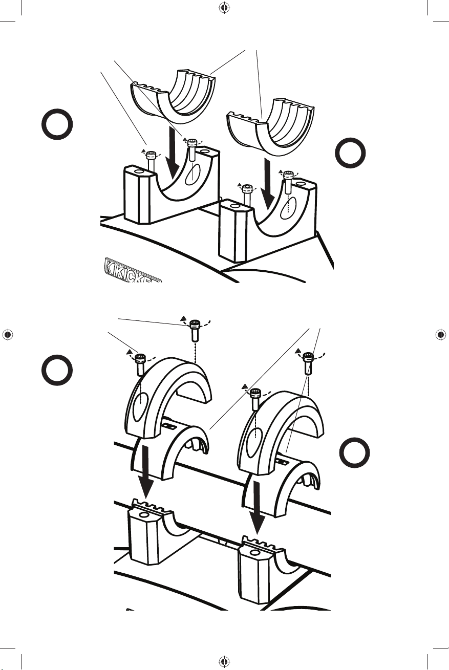
stainless steel sockethead cap screws
(1/4” Allen wrench)
1
plastic mounting inserts
supported diameters:
1.625” [42.3mm]
1.75” [44.4mm]
1.875 [47.6mm]
2” [50.8mm]
2.25” [57.2mm]
2.375” [60.3mm]
2.5” [63.5mm]
place and screw
the mounting
bracket bottom
to the top of the
KMT60 enclosure
stainless steel sockethead cap screws
(1/4” Allen wrench)
4
place and screw
the mounting
bracket top to
the mounting
bracket bottom
2
place mounting
inserts
mounting bracket bottom
plastic mounting inserts
mounting
bracket top
mounting bracket top
3
place remaining
mounting inserts
3
2011 KMT6 Rev B.indd 32011 KMT6 Rev B.indd 3 12/6/2010 4:22:02 PM12/6/2010 4:22:02 PM
Page 4
Wiring: If pre-existing speaker wiring is not available in your desired mounting location, it may be necessary to
run the wire through the wakeboarding tower or roll bar on your vehicle. The speaker wire should be kept away
from sharp edges to avoid the possibility of getting pinched by moving mechanisms and be out of the way of all
passengers and party-goers. If you must drill a hole to run the speaker wire through any location, be careful not
to drill into other wiring or existing mechanisms. Any time a wire is run through a hole, it is necessary to insert a
rubber or plastic grommet to protect the wire from damage. Check your local building codes for the necessary
procedures and precautions for running low voltage wiring in your home or indoor skatepark.
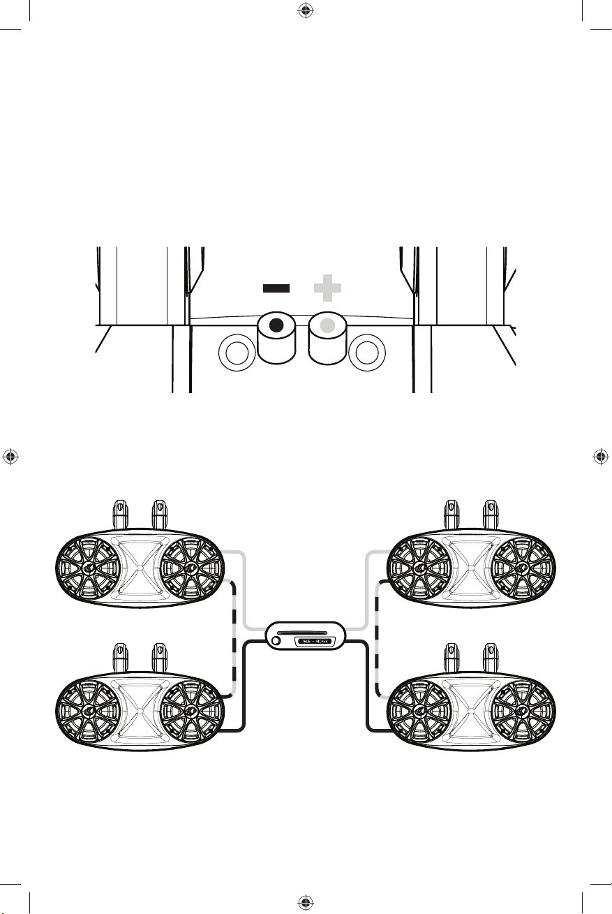
Once the speaker wiring job is fi nished, plug the speaker wires securely into the positive (red dot on the speaker
connector) and negative (black dot on the speaker connector) fi ve-way speaker terminals on the top-rear area
of the KMT60 long-range tower system enclosure. Maintain proper polarity between all KMT60 speakers. Most
speaker wires are marked with a solid or dashed line on one of the two speaker wires. Use this solid or dashed
line as the positive polarity throughout the entire speaker system. The other end of these wires connect to your
source unit or amplifi er in a similar manner, observing proper polarity.
rear view
Modern high performance speakers have a lower working Impedance than what used to be available. The
KICKER KMT60 speakers are rated at four ohms and work with any source unit or amplifi er designed to operate
at a four ohm load. If you want to use two KMT60 speakers on each channel of your source unit or amplifi er
wire the speakers in series. This will improve the sound quality, lower the total harmonic distortion and lessen
the thermal load at the source unit or amplifi er, as it will be an eight ohm load. This may prevent an amplifi er from
shutting down due to over-current protection circuitry.
+
-
+
-
If you have any questions about the installation of your KICKER KMT60 enclosure speakers, see the Authorized
KICKER Dealer where you made your purchase. Please E-mail support@kicker.com or call Technical Services at
(405) 624-8583 for specifi c or unanswered questions.
4
2011 KMT6 Rev B.indd 42011 KMT6 Rev B.indd 4 12/6/2010 4:22:03 PM12/6/2010 4:22:03 PM
+
-
+
-
Page 5

ACOUSTICS LIMITED WARRANTY
KICKER warrants this product to be free from defects in material and workmanship under normal use for a period of
THREE (3) MONTHS from date of original purchase with receipt. When purchased from an Authorized KICKER Dealer it
is warranted for ONE (1) YEAR from date of original purchase with receipt. In all cases you must have the original receipt.
Should service be necessary under this warranty for any reason due to manufacturing defect or malfunction during the
warranty period, KICKER will repair or replace (at its discretion) the defective merchandise with equivalent merchandise
at no charge. Warranty replacements may have cosmetic scratches and blemishes. Discontinued products may be
replaced with more current equivalent products. This warranty is valid only for the original purchaser and is not extended
to owners of the product subsequent to the original purchaser. Any applicable implied warranties are limited in duration
to a period of the express warranty as provided herein beginning with the date of the original purchase at retail, and no
warranties, whether express or implied, shall apply to this product thereafter. Some states do not allow limitations on
implied warranties; therefore these exclusions may not apply to you. This warranty gives you specifi c legal rights; however
you may have other rights that vary from state to state.
WHAT TO DO IF YOU NEED WARRANTY OR SERVICE:
Defective merchandise should be returned to your local Authorized Stillwater Designs (KICKER) Dealer for warranty
service. Assistance in locating an Authorized Dealer can be found at www.kicker.com or by contacting Stillwater Designs
directly. You can confi rm that a dealer is authorized by asking to see a current authorized dealer window decal.
If it becomes necessary for you to return defective merchandise directly to Stillwater Designs (KICKER), call the KICKER
Customer Service Department at (405) 624-8510 for a Return Merchandise Authorization (RMA) number. Package only
the defective items in a package that will prevent shipping damage, and return to:
Stillwater Designs, 3100 North Husband St, Stillwater, OK 74075
The RMA number must be clearly marked on the outside of the package. Please return only defective components. The
return of functioning items increases your return freight charges. Non-defective items will be returned freightcollect to you.
For example, if a subwoofer is defective, only return the defective subwoofer, not the entire enclosure. Include a copy
of the original receipt with the purchase date clearly visible, and a “proof-of-purchase” statement listing the Customer’s
name, Dealer’s name and invoice number, and product purchased. Warranty expiration on items without proof-ofpurchase will be determined from the type of sale and manufacturing date code. Freight must be prepaid; items sent
freight-collect, or COD, will be refused.
WHAT IS NOT COVERED?
This warranty is valid only if the product is used for the purpose for which it was designed. It does not cover:
o Damage due to improper installation
o Subsequent damage to other components
o Damage caused by exposure to moisture, excessive heat, chemical cleaners, and/or UV radiation
o Damage through negligence, misuse, accident or abuse. Repeated returns for the same damage may be
considered abuse
o Any cost or expense related to the removal or reinstallation of product
o Speakers damaged due to amplifi er clipping or distortion
o Items previously repaired or modifi ed by any unauthorized repair facility
o Return shipping on non-defective items
o Products with tampered or missing barcode labels
o Products returned without a Return Merchandise Authorization (RMA) number
o Freight Damage
o The cost of shipping product to KICKER
o Service performed by anyone other than KICKER
HOW LONG WILL IT TAKE?
KICKER strives to maintain a goal of 1 week service for all acoustics (subwoofers, midrange drivers, tweeters,
crossovers, etc) returns. Delays may be incurred if lack of replacement inventory or parts is encountered. Failure to
follow these steps may void your warranty. Any questions can be directed to the KICKER Customer Service Department
at (405) 624-8510. Contact your International KICKER dealer or distributor concerning specifi c procedures for your
country’s warranty policies.
Note: All specifi cations and performance fi gures are subject to change. Please visit www.kicker.com for the most
current information.
P.O. Box 459 • Stillwater, Oklahoma 74076 • USA • (405) 624–8510
stillwaterdesigns
11KMT60-B-20101206
5
2011 KMT6 Rev B.indd 52011 KMT6 Rev B.indd 5 12/6/2010 4:22:04 PM12/6/2010 4:22:04 PM
Page 6

Manual del Usuario de la
Torre de largo alcance KMT60
MODELO: KMT60
Distribuidor autorizado de KICKER:
Fecha de compra:
Número de serie del altavoces:
El Sistema de Torre de Largo Alcance KICKER KMT60 está diseñado específi camente para su instalación al aire
libre, gracias a que utiliza un tweeter de titanio montado en una corneta exponencial de 20 mm y dos woofers de 6.5
pulgadas (165 mm) para producir un sonido limpio y fresco a gran distancia. El gabinete ABS moldeado por inyección
y las bocinas tienen un tratamiento UV, además de que son resistentes a las salpicaduras y al mal clima. Los woofers
utilizan un ensamblaje sellado para el cono y el motor, y el hule espuma de celdas abiertas protege al tweeter. Coloque
el KMT60 en su bote o vuélvase creativo con un par de estas bocinas y colóquelas en su garaje, en su 4x4, en las
barras de su Polaris Ranger, o en cualquier otra aplicación en donde se puedan montar sobre barras.
Modelo: KMT60
Diseño de la bocina 2 - canales
Tamaño del woofer | pulgadas [mm] 6 1/2” [165]
Material envolvente del woofer Caucho de butilo
Tamaño del tweeter | pulgadas [mm] 3/4” [20]
Material del domo del tweeter Titanio
Corneta exponencial | pulgadas [mm] 3 1/4” x 6” [83 x 151]
Clasifi cación de impedancia | ohm 4
Resistencia CD | ohm 3
Rango de energía | Watts RMS 25–150
Manejo de picos de corriente | Watts 300
Sensibilidad [SPLo], dB @ 1W, 1 m 93
Rango efectivo de la frecuencia | Hz 50–21k
Alto | pulgadas [mm] 9” [229]
Ancho | pulgadas [mm] 19 1/16” [484]
Fondo | pulgadas [mm] 11” [280]
INSTALACIÓN
Montaje: El sonido producido por el sistema de torre de largo alcance KMT60 es direccional. El gabinete se puede
montar vertical u horizontalmente; los soportes de montaje de aluminio pueden ser colocados en cualquier ángulo para
proporcionar una dirección óptima. Encuentre la mejor ubicación para el sonido estereofónico y, si es necesario, añada
más sistemas KMT60 a la instalación para distribuir y balancear mejor el sonido. Después de determinar las mejores
opciones para el montaje, revise cuidadosamente las áreas en donde colocará el mecanismo de montaje y el cable de
las bocinas. Los soportes de montaje de aluminio del sistema de torre de largo alcance KMT60 utilizan siete juegos de
insertos de plástico ABS que se ajustan a la mayoría de los diámetros de las torres y barras para esquí acuático.
El diseño del mecanismo de montaje ofrece versatilidad en su posición angular para dirigir la salida de las bocinas hacia
una posición que sea ideal para escuchar; sin embargo, no es recomendable modifi car constantemente la posición
de las bocinas después de que han sido montadas. Los lugares especiales para montar bocinas requerirán más
preparación, trabajo y tal vez un mecanismo modifi cado. Si la ubicación para el montaje requiere que usted corte metal,
evite los metales y las abrazaderas estructurales. En cualquier caso, asegúrese de que la bocina no interferirá con los
mecanismos del vehículo ni del bote en donde hará su fi esta.
6
2011 KMT6 Rev B.indd 62011 KMT6 Rev B.indd 6 12/6/2010 4:22:05 PM12/6/2010 4:22:05 PM
Page 7

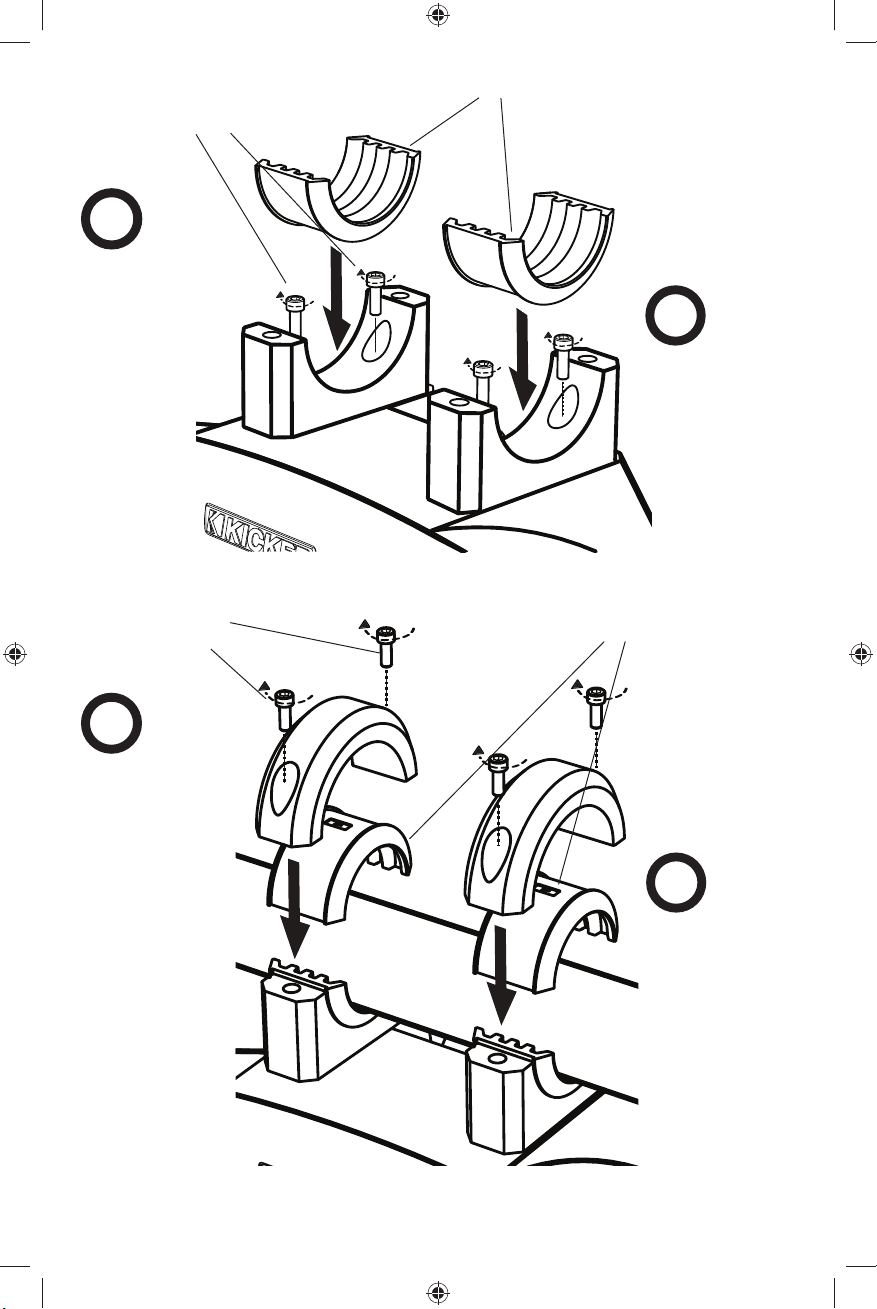
tornillos de cabeza allen
de acero inoxidable
(1/4” llave inglesa de
Allen)
1
insertos de plástico de montaje
diámetros soportados:
1.625” [42.3mm]
1.75” [44.4mm]
1.875 [47.6mm]
2” [50.8mm]
2.25” [57.2mm]
2.375” [60.3mm]
2.5” [63.5mm]
coloque y atornille
la parte inferior del
soporte de montaje
en la parte superior
del gabinete del
KMT60
tornillos de cabeza allen
de acero inoxidable
(1/4” llave inglesa de
Allen)
4
coloque y atornille
la parte superior
del soporte de
montaje en la
parte inferior
del soporte de
montaje
2
coloque los insertos
de montaje
parte inferior del soporte
de montaje
insertos de plástico de montaje
parte superior
del soporte de
montaje
parte superior del
soporte de montaje
3
coloque los
insertos de
montaje restantes
7
2011 KMT6 Rev B.indd 72011 KMT6 Rev B.indd 7 12/6/2010 4:22:05 PM12/6/2010 4:22:05 PM
Page 8
Cableado: Si cable de altavoz no está disponible en su montar deseado la ubicación, puede ser necesario
para correr el cable por la torre de wakeboarding. El cable del altavoz debe ser alejado de orillas agudas para
evitar la posibilidad de ser pellizcado moviendo mecanismos y es fuera de la manera de personas. Si usted
debe taladrar un hoyo para correr la cabina del altavoz; E por ninguna ubicación, tiene cuidado para no taladrar
en otro alambrado ni mecanismos existentes. El tiempo que un cable es corrido por un hoyo, es necesario para
meter un ojal de caucho para proteger el cable del daño. Lea sus códigos locales que construyen para los
procedimientos y precauciones necesarios para empezar a escasear el voltaje cable en su hogar o skatepark
interior.
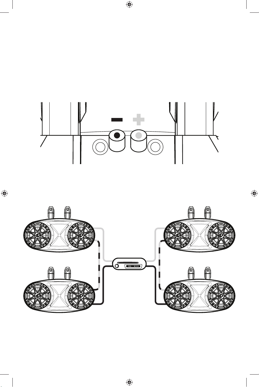
Una vez que el cable del altavoz es colocado, tape los cables del altavoz fi rmemente en las terminales positivas
y negativas de altavoz en la espalda del altavoz KMT60. Usted puede querer quitar el paréntesis que monta para
conseguir una vista clara de las terminales. El rojo es positivo y el negro es negativo. Mantenga la polaridad que
apropiada entre todo altavoces.el KMT60 otro fi n de estos cables conecta a su unidad fuente o el amplifi cador
en una manera semejante.
Terminal del altavoz
Los altavoces modernos de alto rendimiento tienen menor resistencia de CC que la que había antes. Los
altavoces KMT60 de Kicker tienen una impedancia nominal de 4 ohmios y funcionan con cualquier unidad fuente
o amplifi cador diseñado para operar con una carga de 4 ohmios. Si desea usar dos KMT60 en cada canal de su
unidad fuente o amplifi cador, conecte los altavoces en serie, tal como se muestra abajo. Esto mejorará la calidad
del sonido, reducirá la distorsión armónica total y aliviará la carga térmica en la unidad fuente o amplifi cador. Esto
puede prevenir un amplifi cador de apagar, debido a la red de circuitos de protección.
+
-
+
-
Si usted tiene más preguntas sobre la instalación o funcionamiento de su nuevo producto KICKER, vea al
distribuidor autorizado de KICKER donde usted hizo su compra. Para obtener más consejos en la instalación,
haga clic en la lengüeta SUPPORT (SOPORTE) en la página de inicio www.kicker.com. Escoja TECHNICAL
SUPPORT (SOPORTE TÉCNICO), elija el tema que le interese, y luego descargue o vea la información
correspondiente. Por favor envíe correo electrónico a support@kicker.com o llame a servicios técnicos al (405)
624-8583 para preguntas sin respuesta o específi cas.
8
2011 KMT6 Rev B.indd 82011 KMT6 Rev B.indd 8 12/6/2010 4:22:06 PM12/6/2010 4:22:06 PM
+
-
+
-
Page 9

KMT60 Long-range Tower
Benutzerhandbuch
MODELL: KMT60
Autorisierter KICKER-Händler:
Kaufdatum:
Lautsprecher-Seriennummer:
Das KICKER KMT60 Long-Range Tower System ist speziell für den Außenbereich konzipiert worden, ausgerüstet
mit einem 20-mm-Exponential-Hochtonhorn aus Titan und dualen 165-mm-Woofern, um einen reinen und klaren
weitreichenden Klang zu erzeugen. Das aus Spritzguss hergestellte ABS-Gehäuse und die Lautsprecher sind UVbehandelt, spritzdicht und wetterfest. Die Woofer sind mit abgedichteten Kegeln und Motoreinheiten ausgerüstet
und offenzelliger Schaumstoff schützt die Hochtöner. Bauen Sie das KMT60 in ihr Boot ein, oder werden Sie kreativ
und montieren Sie es in Ihrer Garage, in Ihrem Geländewagen, auf einem Polaris-Ranger-Überrollbügel oder anderen
Stangenapplikationen.
Modell: KMT60
Lautsprecherdesign Zweiweg
Woofer Größe | Zoll [mm] 6 1/2” [165]
Woofer Surround-Material Butyl Gummi
Hochtöner Größe | Zoll [mm] 3/4” [20]
Hochtönerkalotte Material Titan
Exponentialhorn | Zoll [mm] 3 1/4” x 6” [83 x 151]
Nennimpedanz | Ohm 4
DC Widerstand | Ohm 3
Leistungsbereich | Watt RMS 25–150
Maximale Belastbarkeit | Watt 300
Empfi ndlichkeit [SPLo], dB @ 1W, 1m 93
Effektiver Frequenzbereich | Hz 50–21k
Höhe | Zoll [mm] 9” [229]
Breite | Zoll [mm] 19 1/16” [484]
Tiefe | Zoll [mm] 11” [280]
INSTALLATION
Einbau: Beim KMT60 Long-range Tower System werden die Klangwellen in eine bestimmte Richtung abgestrahlt.
Das Gehäuse kann senkrecht oder waagerecht angebracht werden; die Befestigungswinkel aus Billet-Aluminium sind
jedem Richtungswinkel anpassbar, um eine optimale Klangabstrahlung zu erzielen. Legen Sie den besten Standort
für Ihr Lautsprechersystem fest, um stereophonen Klang zu erzeugen und falls notwendig fügen Sie weitere KMT60Systeme hinzu, zur besseren Klangverteilung und Aussteuerung. Wenn Sie die beste Befestigungsstelle festgelegt
haben, überprüfen Sie bitte sorgfältig, wo die Befestigungsteile und das Lautsprecherkabel angebracht werden. Die
Befestigungswinkel aus Billet-Aluminium des KMT60 Long-range Tower Systems benutzen sieben Sets von ABSKunststoffeinsätzen und passen somit auf die gängigsten Durchmesser von Wakeboard-Türmen und Überrollbügeln.
Das Design der Befestigungsmaterialien gibt Ihnen genügend Spielraum, um die Lautsprecher für die optimale
Hörposition in jedem Winkel anbringen zu können. Es wird jedoch davon abgeraten, die Lautsprecher allzu sehr zu
verstellen, wenn sie erstmal angebracht worden sind. Für außergewöhnliche Einbauorte oder Befestigungsstellen
benötigen Sie möglicherweise mehr Vorbereitung, sie erfordern evtl. mehr Arbeit und andere spezielle
Befestigungsmaterialien. Falls das Anbringen das Schneiden von Metall erfordert, vermeiden Sie Strukturmetalle und
Streben. In jedem Fall sollten Sie sicherstellen, dass der Lautsprecher weder den Fahrzeugmechanismus noch Ihre
Bootsparty beeinträchtigt.
9
2011 KMT6 Rev B.indd 92011 KMT6 Rev B.indd 9 12/6/2010 4:22:08 PM12/6/2010 4:22:08 PM
Page 10
Edelstahl-Inbusschrauben
(0,25 Zoll Inbusschlüssel)
1
bringen Sie
den unteren
Befestigungswinkel
an der Oberseite des
KMT60-Gehäuses an
und ziehen Sie die
Schrauben fest
EdelstahlInbusschrauben (0,25
Zoll Inbusschlüssel)
Kunststoffeinbauteile
unterstützte
Durchmesser:
1.625” [42,3 mm]
1.75” [44,4 mm]
1.875” [47,6 mm]
2” [50,8 mm]
2.25” [57,2 mm]
2.375” [60,3 mm]
2.5” [63,5 mm]
2
Kunststoffeinbauteile
anbringen
unterer
Befestigungswinkel
Kunststoffeinbauteile
4
bringen Sie
den oberen
Befestigungswinkel
an den unteren
Befestigungswinkel
an und ziehen Sie
die Schrauben fest
10
oberer
Befestigungswinkel
oberer
Befestigungswinkel
3
die restlichen
Kunststoffeinbauteile
anbringen
2011 KMT6 Rev B.indd 102011 KMT6 Rev B.indd 10 12/6/2010 4:22:08 PM12/6/2010 4:22:08 PM
Page 11

Verkabelung: Wenn Lautsprecherkabel nicht verfügbar in Ihrem Befestigungsort ist, dürfen Sie das Kabel durch
den Wakeboarding Turm stellen. Das Lautsprecherkabel sollte fern von scharfen Kanten gehalten werden und
ist aus dem Weg von allen Feiertagenleuten. Wenn Sie ein Loch bohren müssen, das Lautsprecherkabel durch
irgendeinen Ort zu stellen, Seien Sie vorsichtig, in anderen Verdrahten oder Existierenmechanismen nicht zu
bohren. Es ist notwendig, eine Gummitülle einzufügen, das Kabel von Schaden in neuen Löchern zu schützen.
Lesen Sie Ihre örtlichen Gebäudecodes für die notwendigen Verfahren und die Vorsichtsmaßnahmen für
Installieren Niederspannungskabel in Ihrem Heim oder Hallen Skatepark.
Nachdem das Lautsprecherkabel installiert ist, verbinden Sie die Lautsprecherkabel in Lautsprecherterminale den
KMT60 Lautsprecher. Behalten Sie passende Polarität zwischen allen KMT60 Lautsprechern bei. Rot ist positiv
und schwarz ist negativ. Verbinden Sie das andere Ende von den Kabeln zu Ihrer Autoradio oder Verstärker auf
Gleiche Weise.
Hinterer Blick von den
Sprechernterminalen
Moderne Hochleistungslautsprecher verfügen über einen niedrigeren Gleichstromwiderstand, als dies früher der
Fall war. Die KMT60 Lautsprecher haben eine Impedanz von 4 Ohm und sind mit jedem auf 4 Ohm ausgelegten
Autoradio oder Verstärker kompatibel. Wenn Sie zwei Lautsprecher der KMT60-Serie an jeden Kanal Ihres
Autoradios oder Verstärkers anschließen wollen, müssen Sie diese, wie oben gezeigt, in Reihe anschließen. Dies
verbessert die Klangqualität, verringert den Klirrfaktor und reduziert die thermale Belastung des Autoradios oder
Verstärkers. Dies kann einen Verstärker von Abschalten, auf Grund Schutzstromkreises verhindern.
+
-
+
-
Wenn Sie Fragen zur Installation Ihrer KMT60 Long-Range System haben, setzen Sie sich bitte mit dem KickerFachhändler in Verbindung, bei dem Sie die Lautsprecher gekauft haben. Weitere Installationshinweise fi nden
Sie im Bereich SUPPORT auf der Kicker-Internetseite www.kicker.com. Wenn Sie immer noch offene oder sehr
spezifi sche Fragen haben, Senden Sie eine E-Mail an support@kicker.com.
2011 KMT6 Rev B.indd 112011 KMT6 Rev B.indd 11 12/6/2010 4:22:09 PM12/6/2010 4:22:09 PM
+
-
+
-
11
Page 12

Manuel Utilisateur pour la Tour
KMT60 Longue Portée
MODÈLE : KMT60
Revendeur agréé KICKER :
Date d’achat :
Numéro de série
Le système de tour KICKER KMT60 à longue portée est spécifi quement conçu pour être monté en plein air, en utilisant
un haut-parleur d’aigus à pavillon acoustique exponentiel en titane de 20 mm et deux haut-parleurs de graves de 6,5
pouces (165 mm) pour produire un son net et précis sur une longue distance. Le boîtier ABS moulé par injection et
les haut-parleurs sont traités contre les UV, résistant à l’eau et aux perturbations atmosphériques. Les haut-parleurs de
graves utilisent un cône scellé et l’assemblage d’un moteur, et une mousse à cellules ouvertes protège le haut-parleur
d’aigus. Montez le KMT60 dans votre bateau ou faites preuve de créativité en en installant une paire dans le garage, sur
votre 4x4 ou sur les arceaux de sécurité de votre Polaris Ranger, ou dans n’importe quelle autre application montée sur
barre.
Modèle: KMT60
Conception du haut-parleur 2 - voies
Taille du haut-parleur de graves | pouces [mm] 6 1/2” [165]
Matériau ambiophonique du haut-parleur de graves Butyl caoutchouc
Taille du haut-parleur d'aigus | pouces [mm] 3/4” [20]
Matériau du dôme du haut-parleur d'aigus Titane
Pavillon acoustique exponentiel | pouces [mm] 3 1/4” x 6” [83 x 151]
Impédance nominale | ohms 4
Résistance en courant continu | ohms 3
Gamme de puissance | Watts RMS (pression acoustique effi cace) 25–150
Gestion de la puissance de crête | Watts 300
Sensibilité [SPLo], dB @ 1 W, 1 m 93
Gamme de fréquences effective | Hz 50–21k
Hauteur | pouces [mm] 9” [229]
Largeur | pouces [mm] 19 1/16” [484]
Profondeur | pouces [mm] 11” [280]
INSTALLATION
Mounting: Le son produit par le système de tour KMT60 à longue portée est directionnel. Le boîtier peut être monté
verticalement ou horizontalement ; les supports de montage en billette d’aluminium peuvent se monter dans n’importe
quel angle pour une direction du son optimale. Trouvez le meilleur emplacement pour le son stéréophonique et, si
nécessaire, ajoutez un plus grand nombre de systèmes KMT60 à l’installation afi n d’aider à distribuer et équilibrer le
son. Après avoir déterminé les meilleurs emplacements, vérifi ez soigneusement les zones dans lesquelles le matériel de
montage et le câble de l’enceinte seront placés. Le système support, monté sur billette d’aluminium, de la tour KMT60
à longue portée utilise sept séries d’inserts en plastique ABS pour s’adapter à la tour la plus perpendiculaire et aux
diamètres des arceaux de sécurité.
La conception du matériel de montage offre une grande polyvalence de positionnement angulaire pour diriger la sortie du
haut-parleur à la position d’écoute idéale, mais il n’est pas recommandé de repositionner les haut-parleurs trop souvent
après qu’ils aient été montés. Des emplacements de montage personnalisés demandent plus de préparation, de travail
et, éventuellement, de matériel sur mesure. Si l’emplacement de montage vous oblige à couper le métal, évitez les
charpentes métalliques et les crochets. Dans les deux cas, assurez-vous que les haut-parleurs n’interfèrent pas avec les
mécanismes du véhicule ou la fête que vous organisez sur votre bateau ponton.
12
2011 KMT6 Rev B.indd 122011 KMT6 Rev B.indd 12 12/6/2010 4:22:10 PM12/6/2010 4:22:10 PM
Page 13

vis en acier inox à pans
creux de 0,25 pouces
(clé Inbus ™)
1
inserts de montage en plastique
diamètres pris en charge :
1,625” [42,3 mm]
1,75” [44,4 mm]
1,875 [47,6 mm]
2” [50,8 mm]
2,25” [57,2 mm]
2,375” [60,3 mm]
2,5” [63,5 mm]
placer et visser le
support de montage
inférieur vers le haut
du boîtier KMT60
vis en acier inox à pans
creux de 0,25 pouces
(clé Inbus ™)
4
placer et visser
le support de
montage supérieur
vers le support de
montage inférieur
2
placer les inserts
de montage en
plastique
support de montage
inférieur
inserts de montage en plastique
support de
montage
supérieur
support de montage
supérieur
3
placer les inserts
de montage en
plastique restants
13
2011 KMT6 Rev B.indd 132011 KMT6 Rev B.indd 13 12/6/2010 4:22:11 PM12/6/2010 4:22:11 PM
Page 14

Câblage: Si le câble d’haut-parleur n’est pas disponible dans votre monter l’emplacement désiré, ce peut
être nécessaire de placer le câble par la tour de wakeboarding. Le câble d’haut-parleur devrait être évité
des bords tranchants pour éviter la possibilité d’obtenir pincé en déplacant des mécanismes et est à un
endroit où il ne vous gênera pas de tous gens. Si vous devez percer pour courir le câble d’haut-parleur par
n’importe quel emplacement, faites attention de ne pas entraîner dans les autres câbles ou les mécanismes
existants. N’importe quand un câble est couru par un trou, c’est nécessaire d’insérer un oeillet de caoutchouc
pour protéger le câble des dommages. Votre lire vos codes locaux de bâtiment pour les procédures et les
précautions nécessaires pour courir le câble de tension bas votre maison ou skatepark intérieur.
Une fois le câble d’haut-parleur est placé, connecte le câble d’haut-parleur aux terminaux d’haut-parleur sur le
dos du KMT60. Le terminal rouge d’haut-parleur est positif et le terminal d’haut-parleur noir est négatif. Maintenir
la polarité correcte entre tout KMT60 haut-parleurs. L’autre fi n de ces câbles connecte à votre unité de l’appareil
source ou à l’amplifi cateur dans une manière similaire.
La vue postérieure des
terminaux d’haut-parleur
La résistance c.c. des haut-parleurs modernes à hautes performances est inférieure à ce qui existait auparavant.
Les haut-parleurs coaxiaux Kicker KMT60 ont une résistance de 4 ohms et peuvent fonctionner sur tout appareil
source ou amplifi cateur conçu pour une charge de 4 ohms. Vous pouvez utiliser deux haut-parleurs KMT60 sur
chaque canal de l’appareil source ou de l’amplifi cateur en les raccordant en série, comme indiqué ci-dessous.
La qualité sonore est alors améliorée et la distorsion harmonique totale ainsi que la charge thermique vue par
l’appareil source ou l’amplifi cateur sont réduites. Ceci peut empêcher un amplifi cateur de la panne, en raison des
circuits de protection.
+
-
+
-
Si vous avez des questions relatives à l’installation des haut-parleurs Kicker KMT60, contactez le revendeur
agréé Kicker qui vous les a vendus. Pour obtenir d’autres conseils sur l’installation, cliquez sur l’onglet SUPPORT
de la page d’accueil Kicker, www.kicker.com. Sélectionnez le lien Technical Manuals et téléchargez le manuel
technique voulu (format PDF), ou envoyez uncourriel à support@kicker.com. Si vous avez d’autres questions,
téléphonez aux services techniques en composant le (+1) 405-624-8583.
14
2011 KMT6 Rev B.indd 142011 KMT6 Rev B.indd 14 12/6/2010 4:22:12 PM12/6/2010 4:22:12 PM
+
-
+
-
Page 15

INTERNATIONAL WARRANTY
Contact your International KICKER dealer or distributor concerning specifi c procedures for your country’s warranty policies.
WARNING: KICKER products are capable of producing sound levels that can permanently damage your hearing! Turning up a
system to a level that has audible distortion is more damaging to your ears than listening to an undistorted system at the same
volume level. The threshold of pain is always an indicator that the sound level is too loud and may permanently damage your
hearing. Please use common sense when controlling volume.
GARANTÍA INTERNACIONAL Versión Español
Comuníquese con su concesionario o distribuidor KICKER internacional para obtener información sobre procedimientos
específi cos relacionados con las normas de garantía de su país.
ADVERTENCIA: Los excitadores KICKER son capaces de producir niveles de sonido que pueden dañar permanentemente
el oído. Subir el volumen del sistema hasta un nivel que produzca distorsión es más dañino para el oído que escuchar un
sistema sin distorsión al mismo volumen. El dolor es siempre una indicación de que el sonido es muy fuerte y que puede dañar
permanentemente el oído. Sea precavido cuando controle el volumen.
La frase “combustible para vivir la vida Livin’ Loud™ a todo volumen” se refi ere al entusiasmo por la vida que la marca KICKER
de estéreos de automóvil representa y a la recomendación a nuestros clientes de que vivan lo mejor posible (“a todo volumen”)
en todo sentido. La línea de altavoces y amplifi cadores KICKER es la mejor del mercado de audio de automóviles y por lo tanto
representa el “combustible” para vivir a todo volumen en el área de “estéreos de automóvil” de la vida de nuestros clientes.
Recomendamos a todos nuestros clientes que obedezcan todas las reglas y reglamentos locales sobre ruido en cuanto a los
niveles legales y apropiados de audición fuera del vehículo.
INTERNATIONALE GARANTIE Deutsche Version
Nehmen Sie mit Ihren internationalen KICKER-Fachhändler oder Vertrieb Kontakt auf, um Details über die Garantieleistungen in
Ihrem Land zu erfahren.
WARNUNG: KICKER-Treiber können einen Schallpegel erzeugen, der zu permanenten Gehörschäden führen kann! Wenn Sie ein
System auf einen Pegel stellen, der hörbare Verzerrungen erzeugt, schadet das Ihren Ohren mehr, als ein nicht verzerrtes System
auf dem gleichen Lautstärkepegel. Die Schmerzschwelle ist immer eine Anzeige dafür, dass der Schallpegel zu laut ist und zu
permanenten Gehörschäden führen kann. Seien Sie bei der Lautstärkeeinstellung bitte vernünftig!
Der Slogan “Treibstoff für Livin’ Loud” bezieht sich auf die mit den KICKER-Autostereosystemen assoziierte Lebensfreude und die
Tatsache, dass wir unsere Kunden ermutigen, in allen Aspekten ihres Lebens nach dem Besten (“Livin’ Loud”) zu streben. Die
Lautsprecher und Verstärker von KICKER sind auf dem Markt für Auto-Soundsysteme führend und stellen somit den “Treibstoff”
für das Autostereoerlebnis unserer Kunden dar. Wir empfehlen allen unseren Kunden, sich bezüglich der zugelassenen und
passenden Lautstärkepegel außerhalb des Autos an die örtlichen Lärmvorschriften zu halten.
GARANTIE INTERNATIONALE Version Française
Pour connaître les procédures propres à la politique de garantie de votre pays, contactez votre revendeur ou distributeur
International KICKER.
AVERTISSEMENT: Les haut-parleurs KICKER ont la capacité de produire des niveaux sonores pouvant endommager l’ouïe de
façon irréversible ! L’augmentation du volume d’un système jusqu’à un niveau présentant une distorsion audible endommage
davantage l’ouïe que l’écoute d’un système sans distorsion au même volume. Le seuil de la douleur est toujours le signe que le
niveau sonore est trop élevé et risque d’endommager l’ouïe de façon irréversible. Réglez le volume en faisant prevue de bon sens!
L’expression “ carburant pour vivre plein pot “ fait référence au dynamisme de la marque KICKER d’équipements audio pour
véhicules et a pour but d’encourager nos clients à faire le maximum (“ vivre plein pot “) dans tous les aspects de leur vie. Les
haut-parleurs et amplifi cateurs KICKER sont les meilleurs dans le domaine des équipements audio et représentent donc pour nos
client le “ carburant pour vivre plein pot “ dans l’aspect “ installation audio de véhicule “ de leur vie. Nous encourageons tous nos
clients à respecter toutes les lois et réglementations locales relatives aux niveaux sonores acceptables à l’extérieur des véhicules.
P.O. Box 459 • Stillwater, Oklahoma 74076 • USA • (405) 624–8510
11KMT60-B-20101206
15
2011 KMT6 Rev B.indd 152011 KMT6 Rev B.indd 15 12/6/2010 4:22:13 PM12/6/2010 4:22:13 PM
Page 16

©2010 Stillwater Designs
2011 KMT6 Rev B.indd 162011 KMT6 Rev B.indd 16 12/6/2010 4:22:14 PM12/6/2010 4:22:14 PM
 Loading...