


BX AMPLIFIER
BX350.1
BX550.1
English Version
Deutsche Version
BX

2
BX AMPLIFIERS
BX.1-SERIES AMPLIFIERS Owner’s Manual
PERFORMANCE
Authorized KICKER Dealer:
Purchase Date:
Model Number:
Serial Number:
Model: BX350.1 BX550.1
RMS Power, all channels driven
@ 14.4V, 4Ω ≤ 1% THD+N
@ 14.4V, 2Ω ≤ 1% THD+N
200W x 1
350W x 1
300W x 1
550W x 1
Length 300mm 370mm
Specifications common to all models:
Height 54mm
Width 220mm
Frequency Response ± 1dB 5Hz–30000Hz
Signal-to-noise Ratio >95dB, A-weighted, re: rated power
Input Sensitivity Low Level:
200mV–4V
High Level:
500mV–10V
Selectable Electronic Crossover OFF (bypass)
LP/BP variable | 50–200Hz, 12dB/octave
HP variable | 10–50Hz, 12dB/octave
Bass Boost Variable | 0–12dB @ 40Hz
MODEL: BX350.1 / BX500.1
3
BX AMPLIFIERS
INSTALLATION
Mounting: Choose a structurally sound location to mount your KICKER amplifier. Avoid any damage of the
vehicle’s components like wires, cables, board computer, seat belts, gastank where the screws be driven.
Ensure that this chosen location provide sufficient air circulation for the amplifier. Do not mount the device into
small or sealed spaces without air circulation near by heat dispersing parts or electrical parts of the vehicle. Do
not mount the amplifier on top of a subwooferbox or any other vibrating parts, thereby parts in the inside of the
amplifier may get loosen. Drill four holes using a 3mm bit and use the supplied screws to mount the amplifier.
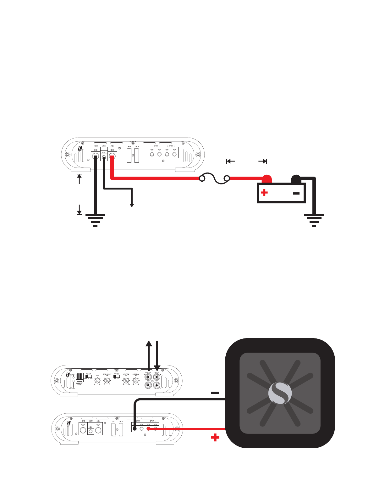
Wiring: Disconnect the ground connection of vehicle’s battery to avoid an electrical short. Then, connect the
ground wire to the amplifier. Connect the GROUND terminal with a suitable contact ground point on the vehicle’s
chassis. The ground wire must be as short as possible and must be connected to a blank metallic point at the
vehicle’s chassis. Ensure that this ground point has a stable and safe electric connection to the negative “–”pole
of the battery. Check this ground wire from the battery to the ground point if possible and enforce it, if required.
Adding an additional ground wire of a larger gauge between the battery’s negative post and the vehicle chassis is
recommended.
12V
battery
external fuse
BX350.1 50 A
BX550.1 60 A
remote turn-on
from source unit
bare-metal
chassis ground
≤
30cm
≤
60cm
Install a fuse within 30cm of the battery and in-line with the power cable connected to your amplifier. If you ever
need to remove the amplifier from the vehicle after it has been installed, the ground wire should be the last wire
disconnected from the amplifier-just the opposite as when you installed it.
OPERATION WITH 1 SUBWOOFER
minimum impedance of 2 ohms
signal insignal out
woofer
4
BX AMPLIFIERS
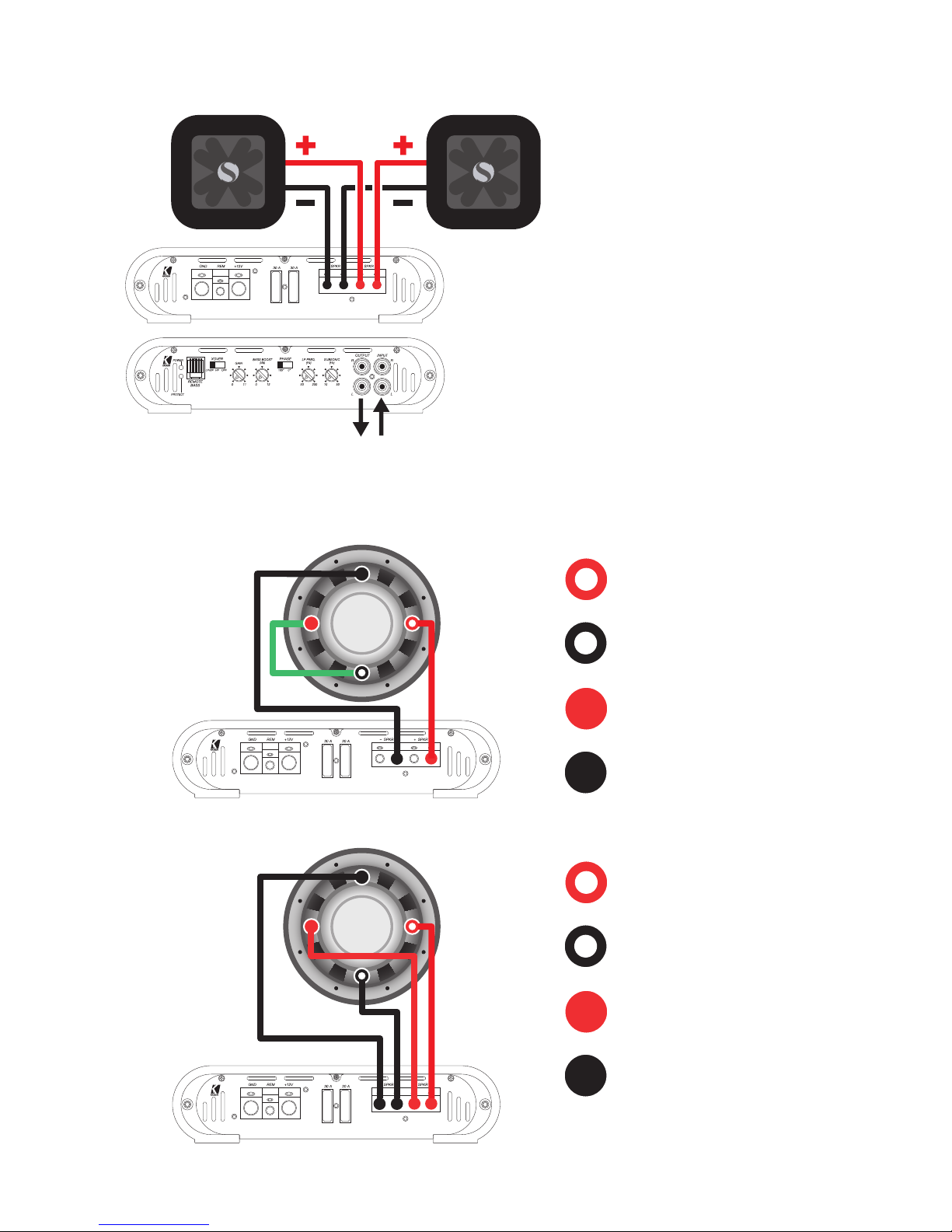
DUAL VOICE COIL INSTALLATION
signal insignal out
OPERATION WITH 2 SUBWOOFERS
minimum impedance of 4 ohms each subwoofer
woofer 1 woofer 2
Coil 1 +
Coil 1 -
Coil 2 +
Coil 2 -
One 2 x 2 ohm woofer
wired in serial
for a 4 ohm load
2 Ohms
2 Ohms
Coil 1 +
Coil 1 -
Coil 2 +
Coil 2 -
One 2 x 4 ohm woofer
wired in parallel
for a 2 ohm load
4 Ohms
4 Ohms

5
BX AMPLIFIERS
OPERATION
Xover Switch: Use the XOVER switch of the amplifier to set the internal crossover to LP/BP, HP (Subsonic) or
OFF. When the switch is set to OFF, a full bandwidth signal will be amplified. Set the switch to HP if you want the
amplifier’s internal crossover to serve as a highpass filter (SUBSONIC controller). Set the switch to LP/BP if you
want the amplifier’s internal crossover to serve as a low-pass filter. Additionally the SUBSONIC-controller works
in this mode to cut-off too low and annoying bass frequencies. Never change the crossover “LP/BP-HP-OFF”
switch setting with the audio system on!
Gain Control: The input gain control is not a volume control. It matches the output of the source unit to the
input level of the amplifier. Turn the source unit up to about 3/4 volume (if the source unit goes to 30, turn it to
25). Next, slowly turn (clockwise) the gain on the amplifier up until you can hear audible distortion, then turn it
down a little.
Bass Boost Control: The variable bass boost control is designed to give you increased output, 0–12dB, at
40 Hz. The setting for this control is subjective. If you turn it up, you must readjust the input gain control to avoid
clipping the amplifier.
Phase Switch: The phase switch is designed to change the phase of the audio signal from 0° to 180°. The
setting for this switch is subjective and depends on the interior characteristics of your vehicle.
LP Freq/Subsonic Control: The LP-control allows you to adjust the low-pass crossover frequency from
50–200Hz. The settings for this control is subjective; 80Hz is a good place to start. The subsonic-control allows
you in the LP/BP-mode to adjust the crossover frequency from 10-50Hz to cut-off ultra-deep frequencies in
the bass-signal. The settings for this control is subjective; 20Hz is a good place to start. In the HP-mode the
subsonic-control allows you to adjust the crossover frequency from 10-50 Hz.
Remote Bass-BXRC: When the crossover on your BX amplifier is set to LP/BP pass, you have the ability to
control the output level of the amplifier remotely. To mount the BXRC remote bass level control, simply screw
the housing to the chosen location. Run the cable from the controller to the “Remote Bass” jack on the amplifier
chassis.
 Loading...