


Service Guide
HP 70909A/70910A
RF Section
ABCDE
HP Part No. 70909-90035
Printed in USA June 1998
Edition A.0.0
Notice
The information contained in this document is subject to change without notice.
Hewlett-Packard makes no warranty of any kind with regard to this material, including,
but not limited to, the implied warranties of merchantability and tness for a particular
purpose. Hewlett-Packard shall not be liable for errors contained herein or for incidental or
consequential damages in connection with the furnishing, performance, or use of this material.
Restricted Rights Legend.
Use, duplication, or disclosure by the U.S. Government is subject to restrictions as set forth
in subparagraph (c) (1) (ii) of the Rights in Technical Data and Computer Software clause at
DFARS 252.227-7013 for DOD agencies, and subparagraphs (c) (1) and (c) (2) of the Commercial
Computer Software Restricted Rights clause at FAR 52.227-19 for other agencies.
c
Copyright Hewlett-Packard Company 1998
All Rights Reserved. Reproduction, adaptation, or translation without prior written permission
is prohibited, except as allowed under the copyright laws
1400 Fountaingrove Parkway, Santa Rosa, CA 95403-1799, USA
.

Certication
Hewlett-Packard Company certies that this product met its published specications at the
time of shipment from the factory. Hewlett-Packard further certies that its calibration
measurements are traceable to the United States National Institute of Standards and
Technology, to the extent allowed by the Institute's calibration facility, and to the calibration
facilities of other International Standards Organization members.
Warranty
This Hewlett-Packard instrument product is warranted against defects in material and
workmanship for a period of one year from date of shipment. During the warranty period,
Hewlett-Packard Company will, at its option, either repair or replace products which prove to
be defective.
For warranty service or repair, this product must be returned to a service facility designated by
Hewlett-Packard. Buyer shall prepay shipping charges to Hewlett-Packard and Hewlett-Packard
shall pay shipping charges to return the product to Buyer. However, Buyer shall pay all
shipping charges, duties, and taxes for products returned to Hewlett-Packard from another
country.
Hewlett-Packard warrants that its software and rmware designated by Hewlett-P
ackard for
use with an instrument will execute its programming instructions when properly installed on
that instrument. Hewlett-Packard does not warrant that the operation of the instrument, or
software, or rmware will be uninterrupted or error-free.
Limitation of Warranty
The foregoing warranty shall not apply to defects resulting from improper or inadequate
maintenance by Buyer, Buyer-supplied software or interfacing, unauthorized modication or
misuse, operation outside of the environmental specications for the product, or improper
site preparation or maintenance.
NO OTHER WARRANTY IS EXPRESSED OR IMPLIED. HEWLETT-PACKARD SPECIFICALLY
DISCLAIMS THE IMPLIED WARRANTIES OF MERCHANTABILITY AND FITNESS FOR A
PARTICULAR PURPOSE.
Exclusive Remedies
THE REMEDIES PROVIDED HEREIN ARE BUYER'S SOLE AND EXCLUSIVE REMEDIES.
HEWLETT-PACKARD SHALL NOT BE LIABLE FOR ANY DIRECT, INDIRECT, SPECIAL,
INCIDENTAL, OR CONSEQUENTIAL DAMAGES, WHETHER BASED ON CONTRACT, TORT,
OR ANY OTHER LEGAL THEORY.
Assistance
Product maintenance agreements and other customer assistance agreements are available for
Hewlett-Packard products.
For any assistance, contact your nearest Hewlett-Packard Sales and Service Oce.
iii

Safety Symbols
The following safety symbols are used throughout this manual. Familiarize yourself with each
of the symbols and its meaning before operating this instrument.
The
CAUTION
WARNING
DANGER
CAUTION
not correctly performed or adhered to, could result in damage to or destruction
of the product or the user's work. Do not proceed beyond a
until the indicated conditions are fully understood and met.
The
WARNING
which, if not correctly performed or adhered to, could result in injury
to the user. Do not proceed beyond a
conditions are fully understood and met.
The
DANGER
reader of a procedure which, if not correctly performed or adhered to,
could result in injury or loss of life. Do not proceed beyond a
sign until the indicated conditions are fully understood and met.
sign denotes a hazard. It calls attention to a procedure which, if
CAUTION
sign denotes a hazard. It calls attention to a procedure
WARNING
sign denotes an imminent hazard to people. It warns the
sign until the indicated
sign
DANGER
iv
General Safety Considerations
WARNING
WARNING
The instructions in this document are for use by qualied personnel
only.To avoid electrical shock, do not perform any servicing unless you
are qualied to do so.
The opening of covers or removal of parts is likely to expose dangerous
voltages. Disconnect the instrument from all voltage sources while it is
being opened.
The power cord is connected to internal capacitors that may remain live
for ve seconds after disconnecting the plug from its power supply.
This is a Safety Class 1 Product (provided with a protective earthing
ground incorporated in the power cord). The mains plug shall only be
inserted in a socket outlet provided with a protective earth contact.
Any interruption of the protective conductor inside or outside of the
instrument is likely to make the instrument dangerous. Intentional
interruption is prohibited.
For continued protection against re hazard, replace fuse only with
same type and ratings, (type nA/nV). The use of other fuses or materials
is prohibited.
Before this instrument is switched on, make sure it has been properly
grounded through the protective conductor of the ac power cable to a
socket outlet provided with protective earth contact.
Any interruption of the protective (grounding) conductor, inside
or outside the instrument, or disconnection of the protective earth
terminal can result in personal injury.
Before this instrument is switched on, make sure its primary power
circuitry has been adapted to the voltage of the ac power source
.
Failure to set the ac power input to the correct voltage could cause
damage to the instrument when the ac power cable is plugged in.
v

Contents
1. Getting Started
Overview of Servicing ............................ 1-2
Contacting Hewlett-Packard for Servicing or Ordering Parts ...... .... 1-6
2. Installing and Conguring Module Verication Software
Computer Software Requirements .. ...... ...... ...... .. 2-2
Computer Hardware Requirements ...... ...... ..... ..... 2-3
Installing Software and Creating Working Copies . . . . . . . . . . . . . . . . 2-5
Conguring Module Verication Software .... ...... ...... ... 2-11
Working with the
Working with the
TSCRIPT
MS_TABLE
File . . . . . . . . . . . . . . . . . . . . . . . . 2-16
Data File . . . . . . . . . . . . . . . . . . . . .
3. Running Module Verication Software
Loading from an SRM or HFS Hard Disk . . . . . . . . . . . . . . . . . . . .
Entering Information About Your RF Section (UUT) ...... ...... ..
Running from the Main Test Menu ......................
Working with the Calibration Editor .....................
4. Test Equipment and Calibrations
Test Equipment Requirements ........................
Test Equipment Calibrations .........................
Spectrum Analyzer Calibration ........................
Flatness Calibration ...... ...... ...... ...... .....
External Frequency Reference Requirements .................
2-23
3-2
3-3
3-10
3-12
4-2
4-5
4-6
4-7
4-9
5. Adjustment Procedures
Before You Begin Adjustments .. ...... ...... ...... .... 5-2
Overall Adjustment Setup .......... ...... ...... .... 5-4
Adjustment 01. Power Supply Voltage Checks . . . . . . . . . . . . . . . . . 5-5
Adjustment 02. 1st LO Power . . . . . . . . . . . . . . . . . . . . . . . . . 5-7
2nd Converter Adjustments . . . . . . . . . . . . . . . . . . . . . . . . . . 5-10
Adjustment 03.01 VCO Tune-Line Voltage ...................
Adjustment 03.02 VCO Frequency and Amplitude ...............
Adjustment 03.03 2nd Converter LO Feedthrough .. ...... ...... .
Adjustment 03.04 Sampler DC IF Out .....................
Adjustment 03.05 Sampler AC IF Out .... ...... ...... .....
Adjustment 03.06 Search Oscillator Duty Cycle and Period .... ...... . 5-21
Adjustment 03.07 Search Oscillator Square Wave Min/Max .. ...... ... 5-23
Adjustment 03.08 Search Oscillator VCO Tune Line .............. 5-25
Adjustment 03.09 Phase Lock . . . . . . . . . . . . . . . . . . . . . . . . . 5-27
Adjustment 03.10 VCO Tune Range . . . . . . . . . . . . . . . . . . . . . . 5-29
Adjustment 03.11 Lock Range Measurement . . . . . . . . . . . . . . . . . .
Adjustment 03.12 Bandpass Filter and VCO Tune Range Final . . . . . . . . . .
Adjustment 03.13 Mixer Bias . . . . . . . . . . . . . . . . . . . . . . . . .
Adjustment 04. Last Converter Alignment . . . . . . . . . . . . . . . . . . .
Adjustment 05. PGA Calibration .......................
5-11
5-13
5-15
5-17
5-19
5-32
5-34
5-37
5-39
5-44
Contents-1

Adjustment 06. YTF Alignment . . . . . . . . . . . . . . . . . . . . . . . . 5-46
6. Verication Tests
Before You Begin Testing . . . . . . . . . . . . . . . . . . . . . . . . . . . 6-2
Overall Test Setup . . . . . . . . . . . . . . . . . . . . . . . . . . . . . . 6-4
Test 01. Switch Repeatability - HP 70910A Only . . . . . . . . . . . . . . . . 6-5
Test 02. External Mixer Gain Calibration ................... 6-7
Test 03. Gain and Flatness Calibration .................... 6-9
Test 04. Flatness Below 50 MHz ....................... 6-11
Test 05. Microwave Gain and Noise Figure .... ...... ...... .. 6-13
Test 06. External Mixer Noise Figure ..................... 6-17
Test 07. Microwave TOI ........................... 6-19
Test 08. Diagnostics Check . . . . . . . . . . . . . . . . . . . . . . . . . . 6-22
Test 09. Front Panel LEDs Check . . . . . . . . . . . . . . . . . . . . . . . 6-24
Test 10. 21.4 MHz IF Output Response .................... 6-25
Test 11. IF Emissions and Harmonics .. ...... ..... ...... .. 6-27
Test 12. EMIM LO Out Power and Harmonics ................. 6-29
Test 13. 1st LO Out Power and Harmonics . . . . . . . . . . . . . . . . . . . 6-31
Test 14. TUNE+SPAN+PRESEL PEAK Output .. ...... ...... .. 6-33
Test 15. LO Input Amplitude Range . . . . . . . . . . . . . . . . . . . . . . 6-35
Test 16. Microwave Image Rejection .....................
Test 17. EMIM Image Rejection . . . . . . . . . . . . . . . . . . . . . . . .
Test 18. 2nd Converter Startup . . . . . . . . . . . . . . . . . . . . . . . .
Test 19. Microwave Residual Responses . . . . . . . . . . . . . . . . . . . .
Test 20. Microwave In-Range Multiples ...... ...... ...... ..
Test 21. 321.4 MHz IF Output Bandwidth - HP 70910A Only
..........
6-37
6-39
6-41
6-43
6-45
6-47
7. Troubleshooting
Preparing a Static-Safe Work Station .... ...... ...... .....
Power-On Failures . . . . . . . . . . . . . . . . . . . . . . . . . . . . . .
Display Problems .......... ...... ..... ...... ...
Mainframe Problems . . . . . . . . . . . . . . . . . . . . . . . . . . . . .
Communication Problems on the HP-MSIB I/O . . . . . . . . . . . . . . . . .
Error Messages .......... ...... ...... ..... ....
Adjustment Problems ............................
Verication Test Problems .......................... 7-23
Troubleshooting the A2 RF First Converter ........ ...... .... 7-30
Troubleshooting the A5, A7, A8, A9 Second Converter . . . . . . . . . . . . . 7-31
Troubleshooting the A6 Programmable Gain Amplier ............. 7-34
Troubleshooting the A10 Last Converter ................... 7-36
Troubleshooting the A11 5 dB Step Attenuator .. ...... ...... ..
Troubleshooting the A12 RF Switch/A15 RF Switch and A21 Pin Switch/Diplexer
Troubleshooting the A14 YTF and A19 Power Supply/YTF Driver . . . . . . . .
Troubleshooting the A16 Preamp/Mixer . . . . . . . . . . . . . . . . . . . .
Troubleshooting the A18 LO Leveling Amplier .... ...... ...... 7-44
Troubleshooting the A20 Controller . . . . . . . . . . . . . . . . . . . . . .
Performing Related Adjustments and Verication Tests . . . . . . . . . . . . . 7-47
Troubleshooting Utilities Menu ........................
Overall Block Diagram of HP 70909A or HP 70910A RF section . . . . . . . . . 7-53
7-2
7-4
7-5
7-9
7-10
7-13
7-17
7-38
7-39
7-40
7-43
7-45
7-50
Contents-2
8. Replacing Major Assemblies
Module Cover .. ...... ...... ..... ...... ...... . 8-2
Front Panel ................................. 8-4
Rear Panel ................................. 8-6
A2 RF First Converter ............................ 8-8
A5, A7, A8, A9 Second Converter ...................... 8-10
A6 Programmable Gain Amplier . . . . . . . . . . . . . . . . . . . . . . . 8-12
A10 Last Converter ............................. 8-14
A11 5 dB Step Attenuator .......................... 8-16
A12 RF Switch/A15 RF Switch (HP 70910A RF Section Only) . . . . . . . . . . 8-18
A14 YTF .................................. 8-20
A16 Preamp/Mixer . . . . . . . . . . . . . . . . . . . . . . . . . . . . . . 8-22
A18 LO Leveling Amplier . . . . . . . . . . . . . . . . . . . . . . . . . . 8-24
A19 Power Supply/YTF Driver Service Position ...... ...... .... 8-26
A19 Power Supply/YTF Driver ........................ 8-28
A20 Controller . . . . . . . . . . . . . . . . . . . . . . . . . . . . . . . . 8-30
A22 Status ................................. 8-32
9. Overall Parts Identication Drawings
Major Cables and Assemblies . . . . . . . . . . . . . . . . . . . . . . . . . 9-2
Front View Identication . . . . . . . . . . . . . . . . . . . . . . . . . . .
Right Side View Identication .... ...... ...... ...... ..
Left Side View Identication, Exploded . . . . . . . . . . . . . . . . . . . .
Rear View Identication ...........................
9-8
9-9
9-14
9-16
Index
Contents-3
Figures
1-1. Typical Serial Number Label .... ...... ...... ..... ... 1-6
3-1. Typical Serial Number Label .... ...... ...... ..... ... 3-3
4-1. Spectrum Analyzer Calibration Setup . . . . . . . . . . . . . . . . . . . . 4-6
4-2. Flatness Calibration and Verication Test Setup ........ ..... .. 4-7
4-3. Frequency Reference Connections, Using an HP 70310A Precision Frequency
Reference ............................... 4-10
4-4. Frequency Reference Connections, Using the HP 8566B Spectrum Analyzer . . 4-11
5-1. Adjustments Equipment Matrix . . . . . . . . . . . . . . . . . . . . . . . 5-2
5-2. Overall Adjustment Equipment Setup . . . . . . . . . . . . . . . . . . . . 5-4
5-3. Equipment Setup for Adjustment 01. Power Supply Voltage Checks . . . . . . 5-5
5-4. Location of A19J8-1 . . . . . . . . . . . . . . . . . . . . . . . . . . . . 5-6
5-5. Equipment Setup for Adjustment 02. 1st LO Power .............
5-6. Side View Location of Adjustment 02. 1st LO Power . . . . . . . . . . . . .
5-7. PROTECT/ENABLE Switch Location ....................
5-8. 2nd Converter Adjustment Locations .. ...... ...... ......
5-9. 2nd Converter Adjustment Locations .. ...... ...... ......
5-10. Equipment Setup for Adjustment 03.01 VCO Tune-Line Voltage . . . . . . . .
5-11. Locations for Adjustment 03.01 VCO Tune-Line Voltage ...........
5-12. Equipment Setup for Adjustment 03.02 VCO Frequency and Amplitude . . . . 5-13
5-13. Locations for Adjustment 03.02 VCO Frequency and Amplitude . . . . . . . .
5-14. Equipment Setup for Adjustment 03.03 2nd Converter LO Feedthrough . . . . 5-15
5-15. Locations for Adjustment 03.03 2nd Converter LO Feedthrough . . . . . . . . 5-15
5-16. Equipment Setup for Adjustment 03.04 Sampler DC IF Out . . . . . . . . . .
5-17. Locations for Adjustment 03.04 Sampler DC IF Out .............
5-18. Equipment Setup for Adjustment 03.05 Sampler ACIFOut..........
5-19. Locations for Adjustment 03.05 Sampler AC IF Out ........ .....
5-20. Equipment Setup for Adjustment 03.06 Search Oscillator Duty Cycle and Period 5-21
5-21. Locations for Adjustment 03.06 Search Oscillator Duty Cycle and Period ... 5-21
5-22. Equipment Setup for Adjustment 03.07 Search Oscillator Square Wave Min/Max 5-23
5-23. Locations for Adjustment 03.07 Search Oscillator Square Wave Min/Max . . . . 5-23
5-24. Equipment Setup for Adjustment 03.08 Search Oscillator VCO Tune Line ... 5-25
5-25. Locations for Adjustment 03.08 Search Oscillator VCO Tune Line . . . . . . .
5-26. Equipment Setup for Adjustment 03.09 Phase Lock ........ .....
5-27. Locations for Adjustment 03.09 Phase Lock .................
5-28. Equipment Setup for Adjustment 03.10 VCO Tune Range . . . . . . . . . . . 5-29
5-29. Locations for Adjustment 03.10 VCO Tune Range .... ...... .... 5-29
5-30. Equipment Setup for Adjustment 03.11 Lock Range Measurement ...... 5-32
5-31. Locations for Adjustment 03.11 Lock Range Measurement ...... .... 5-32
5-32. Equipment Setup for Adjustment 03.12 Bandpass Filter and VCO Tune Range
Final ................................. 5-34
5-33. Locations for Bandpass Filter Tune Range and VCO Tune Range ...... . 5-35
5-34. Equipment Setup for Adjustment 03.13 Mixer Bias . . . . . . . . . . . . . . 5-37
5-35. Locations for Adjustment 03.13 Mixer Bias .................
5-36. Equipment Setup for Adjustment 04. Last Converter Alignment ....... 5-39
5-37. Locations for Adjustment 04. Last Converter Alignment ...........
5-38. Equipment Setup for Adjustment 05. PGA Calibration . . . . . . . . . . . .
5-7
5-7
5-9
5-10
5-10
5-11
5-11
5-13
5-17
5-17
5-19
5-19
5-25
5-27
5-27
5-37
5-40
5-44
Contents-4

5-39. Equipment Setup for Adjustment 06. YTF Alignment ...... ...... 5-46
5-40. A19 OFFSET (R38) and GAIN (R39) Adjustments . . . . . . . . . . . . . . . 5-48
6-1. Verication Tests Equipment Matrix . . . . . . . . . . . . . . . . . . . . . 6-2
6-2. Overall RF Section Verication Test Setup . . . . . . . . . . . . . . . . . . 6-4
6-3. Equipment Setup for Test 01. Switch Repeatability - HP 70910A Only . . . . . 6-5
6-4. Equipment Setup for Test 02. External Mixer Gain Calibration Test Setup . . . 6-7
6-5. Equipment Setup for Test 03. Gain and Flatness Calibration ........ . 6-9
6-6. Equipment Setup for Test 04. Flatness Below 50 MHz .. ...... .... 6-11
6-7. Equipment Setup for Noise Figure Calibration . . . . . . . . . . . . . . . . 6-13
6-8. Equipment Setup for Gain Calibration and Measurement . . . . . . . . . . . 6-14
6-9. Equipment Setup for Test 06. External Mixer Noise Figure . . . . . . . . . . 6-17
6-10. Equipment Setup for Test 07. Microwave TOI .... ...... ...... 6-19
6-11. Equipment Setup for Test 08. Diagnostics Check . . . . . . . . . . . . . . . 6-22
6-12. Equipment Setup for Test 09. Front Panel LEDs Check . . . . . . . . . . . . 6-24
6-13. Equipment Setup for Test 10. 21.4 MHz IF Output Response ........ . 6-25
6-14. Equipment Setup for Test 11. IF Emissions and Harmonics . . . . . . . . . . 6-27
6-15. Equipment Setup for Test 12. EMIM LO Out Power and Harmonics .. .... 6-29
6-16. Equipment Setup for Test 13. 1st LO Out Power and Harmonics ...... . 6-31
6-17. Equipment Setup for Test 14. TUNE+SPAN+PRESEL PEAK Output ..... 6-33
6-18. Equipment Setup for Test 15. LO Input Amplitude Range .... ...... 6-35
6-19. Equipment Setup for Test 16. Microwave Image Rejection ..........
6-20. Equipment Setup for Test 17. EMIM Image Rejection . . . . . . . . . . . . .
6-21. Equipment Setup for Test 18. 2nd Converter Startup ............
6-22. Equipment Setup for Test 19. Microwave Residual Responses . . . . . . . . .
6-23. Equipment Setup for Test 20. Microwave In-Range Multiples . . . . . . . . .
6-24. Equipment Setup for Test 21. 321.4 MHz IF Output Bandwidth . . . . . . . .
7-1. Static-Safe Work Station .. ...... ...... ...... ......
7-2. Line Voltage Selector . . . . . . . . . . . . . . . . . . . . . . . . . . . .
7-3. Line Fuse Removal and Replacement ....................
NNNNNNNNNNNNNNNNNNNNNNNNNNNNNNNNNNNNNNNNN
7-4.
display tests
Menu Keys ........................
7-5. Condence Test ..............................
7-6. Overall Block Diagram of HP 70909A or HP 70910A RF section . . . . . . . .
8-1. Module Cover Removal/Replacement ....................
8-2. Front Panel Removal/Replacement .....................
8-3. Rear Panel Removal/Replacement . . . . . . . . . . . . . . . . . . . . . .
6-37
6-39
6-41
6-43
6-45
6-47
7-2
7-5
7-5
7-7
7-8
7-53
8-3
8-5
8-7
8-4. A2 RF First Converter Removal/Replacement ................ 8-9
8-5. A5, A7, A8, A9 Second Converter Removal/Replacement . . . . . . . . . . . 8-11
8-6. A6 Programmable Gain Amplier Removal/Replacement .... ...... . 8-13
8-7. A10 Last Converter Removal/Replacement .. ...... ...... ... 8-15
8-8. A11 5 dB Step Attenuator Removal/Replacement .............. 8-17
8-9. A12 RF Switch/A15 RF Switch Removal/Replacement ............
8-10. A14 YTF Removal/Replacement . . . . . . . . . . . . . . . . . . . . . . .
8-11. A16 Preamp/Mixer Removal/Replacement . . . . . . . . . . . . . . . . . .
8-19
8-21
8-23
8-12. A18 LO Leveling Amplier Removal/Replacement .............. 8-25
8-13. A19 Power Supply/YTF Driver Service Position ............... 8-27
8-14. A19 Power Supply/YTF Driver Removal/Replacement ............ 8-29
8-15. A20 Controller Removal/Replacement . . . . . . . . . . . . . . . . . . . .
8-16. A22 Status Removal/Replacement . . . . . . . . . . . . . . . . . . . . . .
8-31
8-33
9-1. Overall Parts Identication Drawing, Major Cables (1 of 4) .......... 9-4
9-2. Overall Parts Identication Drawing, Major Cables (2 of 4) .......... 9-5
9-3. Overall Parts Identication Drawing, Major Cables (3 of 4)
9-4. Overall Parts Identication Drawing, Major Cables (4 of 4)
..........
..........
9-5. Overall Parts Identication Drawing, Front View ..............
9-6. Overall Parts Identication Drawing, Right Side View (1 of 4) . . . . . . . . .
9-7. Overall Parts Identication Drawing, Right Side View (2 of 4) . . . . . . . . .
9-6
9-7
9-8
9-10
9-11
Contents-5
9-8. Overall Parts Identication Drawing, Right Side View, Exploded (3 of 4) . . . . 9-12
9-9. Overall Parts Identication Drawing, Right Side View, Exploded (4 of 4) . . . . 9-13
9-10. Overall Parts Identication Drawing, Left Side View, Exploded . . . . . . . . 9-15
9-11. Overall Parts Identication Drawing, Rear View . . . . . . . . . . . . . . . 9-16
Contents-6
Tables
1-1. HP Service Centers ...... ...... ...... ...... .... 1-7
1-2. Packaging for a 2/8 Module (RF Section) . . . . . . . . . . . . . . . . . . . 1-9
7-1. Static-Safe ESD Accessories ...... ...... ..... ...... . 7-3
7-2. Default HP-MSIB Address Map ....................... 7-11
7-3. A11 5 dB Step Attenuator Logic ...................... 7-38
9-1. Cables for the HP 70909A RF Section and HP 70910A RF Section . . . . . . . 9-2
9-2. Assemblies for the HP 70909A RF Section and HP 70910A RF Section . . . . . 9-3
9-3. Overall Parts Identication Listing, Front View ........ ...... . 9-8
9-4. Overall Parts Identication Listing, Right Side View ........ ..... 9-9
9-5. Overall Parts Identication Listing, Left Side View Exploded . . . . . . . . . 9-14
9-6. Overall Parts Identication Listing, Rear View . . . . . . . . . . . . . . . . 9-16
Contents-7

Getting Started
1
Overview
In this chapter you will learn about:
Various types of test software available for your RF section
The organization of this service guide and component-level repair
information
How to contact Hewlett-Packard for servicing or ordering parts
This chapter introduces you to servicing and the various types of test software available for
your RF section. You will rst learn how the service guide and the component-level repair
information (CLIP set) are organized, and then you'll learn how to contact Hewlett-P
ackard for
servicing or ordering replacement parts.
When is Servicing Needed?
Servicing is needed:
if error messages are displayed on your HP 70000 Series display
if an ERROR LED or FAULT LED is on
or, to perform repairs or adjustments or both
If you determine that your RF section needs servicing, you can return your RF section to
a Hewlett-Packard service center, or you can perform the servicing yourself using module
verication software and the information in this service guide
To perform the servicing yourself using module verication software
.
, review the rest of the
information in this chapter, and then proceed to Chapter 2 where you will learn how to install
and congure module verication software.To return your RF section to a Hewlett-Packard
service center for service, refer to \Contacting Hewlett-Packard for Servicing or Ordering
Parts".
Overview of Servicing
:::::: ::::::: :::::: ::::::: ::::::: :::::: ::::::: ::::::: :::::: ::::::: ::::::
Contacting Hewlett-Packard for Servicing or Ordering Parts
::::: ::::::: :::::: ::::::: :::::::
Getting Started 1-1
1-2
1-6
Overview of Servicing
1-2 Getting Started
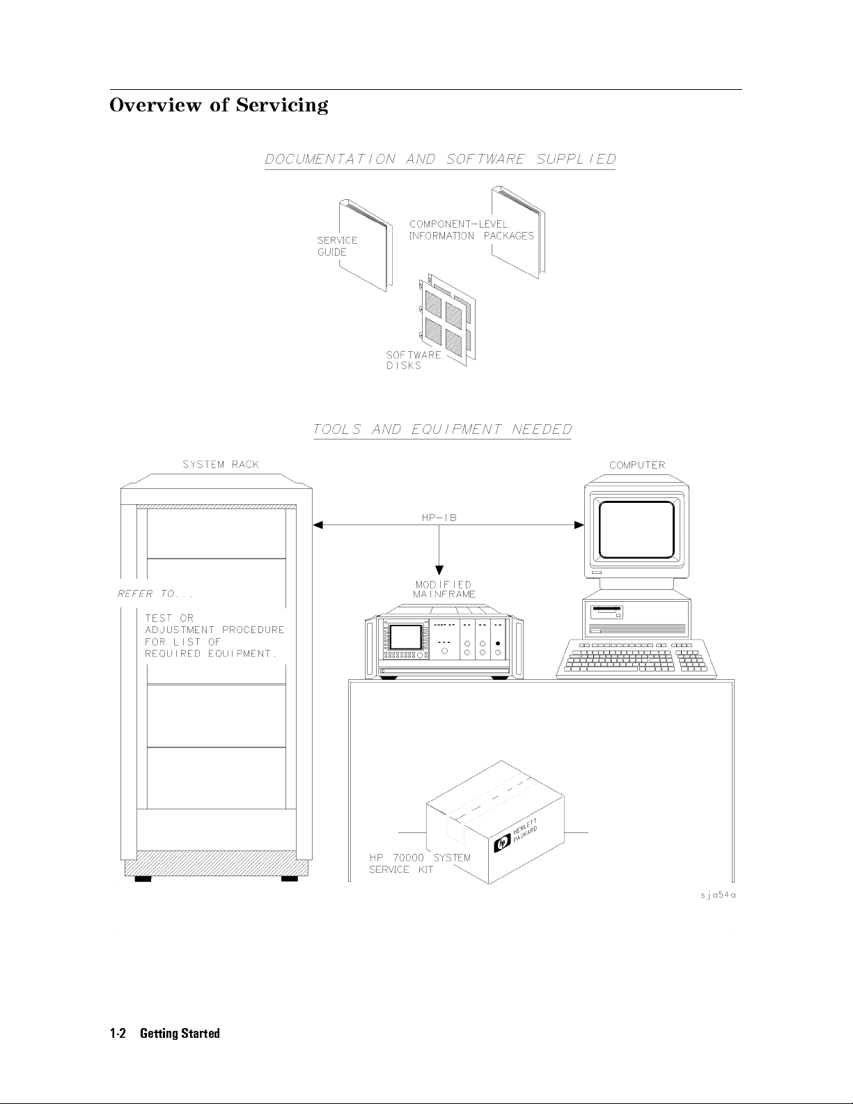
Overview of Servicing
This service guide is part of an Option OB3 package which includes test software and two
manuals.
Test Software
Manual 1
Manual 2
Module Verication Software
HP 70909A/70910A Service Guide
HP 70909A/70910A Component Level Information Package
Types of Test Software Available
There are three categories of test software available, and this service guide documents the use
of module verication tests.
Module Verication
Tests
Module verication tests are used to test modules so that when
assembled into a system, the system meets the system's specications.
Module verication tests are used during servicing.
System Verication
Tests
System verication tests are used to verify the proper operation of
an instrument and to verify that the instrument meets approximately
80% of its measurement related specications
. These sets of tests are
subsets of system performance tests.
System Performance
Tests
System performance tests are used to verify the proper operation
of a complete modular measurement system (MMS) to full system
specications.
For information related to system verication tests, refer to the
Analyzer Installation and Verication Manual
, and for information related to system
HP 70000 Modular Spectrum
performance tests, refer to the documentation for HP 11990A system performance test
software.
Manual 1
This service guide describes all of the service procedures necessary to troubleshoot, repair
,
adjust, and test your RF section . The RF section is a module that is used in HP 70000 Series
modular measurement systems. A standard modular spectrum analyzer system includes a
mainframe with an RF section , IF section , local oscillator, an optional display, and an optional
precision frequency reference.
Chapter 1 \Getting Started"
This chapter introduces you to servicing and the various types of test software available for
your RF section. You will rst learn how the service guide and the component-level repair
information (CLIP set) are organized, and then you'll learn how to contact Hewlett-P
ackard
for servicing or ordering replacement parts.
Chapter 2 \Installing and Conguring Module Verication Software "
This chapter prepares you to install and congure the module verication software for your
RF section. You then learn how to load module verication software and how to change
conguration settings by editing a
TSCRIPT
le. Finally, you'll learn how to use the
MS_TABLE
program to specify dierent storage locations that CAL FACTOR data les and test results
data can be stored and retrieved from.
Chapter 3 \Running Module Verication Software"
This chapter prepares you to run the module verication tests on your RF section. Y
will learn how to load module verication software
parameters about your RF section that are used in creating reports
. Then, you will learn how to change
. From there, you'll learn
ou
Getting Started 1-3

Overview of Servicing
how to run the module verication software tests, and nally, you'll learn how to create,
edit, print, or purge a CAL FACTOR data le using the Calibration Editor program.
Chapter 4 \Test Equipment and Calibrations"
This chapter contains the test equipment setups for all calibration procedures that must
be performed in order to optimize module performance when assemblies are changed,
repaired, or adjusted. You will learn about the requirements as well as when and how often
calibrations are required. Finally, you'll learn about the requirements for the external
frequency reference being used.
Chapter 5 \Adjustment Procedures"
This chapter contains the test equipment setups for all adjustment procedures that are used
to optimize module performance when assemblies are changed, repaired, or adjusted. All of
the setups described in this chapter are automated and require a controller running module
verication software.
Chapter 6 \Verication Tests"
This chapter contains the test equipment setups for all module verication tests that are
used to optimize module performance when assemblies are changed, repaired, or adjusted.
All of the setups described in this chapter are automated and require a controller running
module verication software.
Chapter 7 \Troubleshooting"
This chapter prepares you for troubleshooting your RF section. Y
ou will learn how to prepare
a static-safe work station that is used during servicing. Then, you will learn how to resolve
power-on problems, adjustment problems, and verication test problems. Finally, you'll
learn in-depth circuit troubleshooting as well as which adjustments and verication tests
have to be run to ensure proper operation after an assembly has been repaired, replaced, or
adjusted.
Chapter 8 \Replacing Major Assemblies"
This chapter contains procedures for removal and replacement of major assemblies in your
RF section.
Chapter 9 \Overall Parts Identication Drawings"
This chapter contains information on all overall parts identication drawings that should be
used when performing the troubleshooting procedures described in this service guide.
Index
An index is also added at the end of this service guide to aid the user in nding key items of
interest.
Manual 2
Manual 2 is a separate volume that contains packets of component-level repair information
for each RF section board assembly that has eld-replaceable parts. Each packet includes the
parts list, component-location drawing, and schematics for a specic board-assembly part
number. Manual 2 also contains a table that can be used to cross reference dierent board
assemblies that have dierent serial prex breaks.
1-4 Getting Started
Information Not Covered in Manual 1 or 2
Overview of Servicing
System congurations are documented in the
Installation and Verication Manual
Guide
.
Error codes not covered in the troubleshooting chapter of this manual (Chapter 7) may be
found in the
HP 71910P Wide-Bandwidth Receiver User's Guide
guides.
Each modular measurement system (MMS) module has its own service guide.For further
information related to the servicing of additional and alternate modules that can be used in
this system, refer to each module's service guide.
Before You Begin Servicing
Review the Troubleshooting sections of Chapter 7 as well as the directions for \Installing and
Conguring Test and Adjustment Software" in Chapter 2.
HP 70000 Modular Spectrum Analyzer Installation and Verication Manual
and
HP 70000 Modular Spectrum Analyzer
HP 71910P Wide-Bandwidth Receiver User's
, and additional module specic service
,
Getting Started 1-5

Contacting Hewlett-Packard for Servicing or Ordering Parts
Contact Hewlett-Packard for service or ordering parts.
Service Before calling Hewlett-Packard or returning your RF section for service, please
read your warranty information. Warranty information is printed at the front
of this service guide.
Ordering Parts To order parts, contact the HP Service Center closest to you.
In any correspondence or telephone conversations, refer to the RF section by its full model
number and full serial number. With this information, the Hewlett-Packard representative can
determine whether your unit is still within its warranty period.
Determining Your RF Section's Serial Number
When a module is manufactured by Hewlett-Packard, it is given a unique serial number. This
serial number is attached to a label on the front frame or front panel of the module. A serial
number label is in two parts. (Refer to Figure 1-1.) The rst part makes up the serial number
prex and consists of four digits and a letter. The second part makes up the serial number
sux and consists of the last ve digits on the serial number label. The serial number prex is
the same for all identical modules; it only changes when a change in the electrical or physical
functionality is made. The serial number sux, however, changes sequentially and is dierent
for each module.
1-6 Getting Started
Figure 1-1. Typical Serial Number Label

Contacting Hewlett-Packard for Servicing or Ordering Parts
A current list of Hewlett-Packard Service Centers can be accessed on the Internet at:
http://www.tmo.hp.com/tmo/contacts/
If you do not have access to the Internet, one of the following Hewlett-Packard locations can
direct you to your nearest Hewlett-Packard representative:
Table 1-1. HP Service Centers
United States
Canada
Europe
Japan
Latin America
Austrailia/New
Zealand
Asia-Pacic
Hewlett-Packard Company
Test and Measurement Call Center
(800) 403-0801
(800) 857-8161 (FAX)
Hewlett-Packard Canada Ltd.
5150 Spectrum Way
Mississauga, Ontario L4W 5G1
(905) 206-4725
(905) 206-4739 (FAX)
Hewlett-Packard European Marketing Centre
Postbox 667
1180 AR Arnstelveen
Netherlands
(31/20) 547-6669
(31/20) 647-8706
Hewlett-Packard Japan Ltd.
27-15, Yabe 1-Chome,
Sagamihara, Kanagawa 229
Japan
(81426) 567 832
(81426) 567 843 (FAX)
Hewlett-Packard Latin America Region Headquarters
5200 Blue Lagoon Drive, 9th Floor
Miami, Florida 33126
U.S.A.
(305) 267 4245
(305) 267 4288 (FAX)
Hewlett-Packard Calibration Services Austrailia Ltd.
31-41 Joseph Street
Blackburn, Victoria 3130
Austrailia
1800 802 540
1800 681 776 (FAX)
Hewlett-Packard Asia-Pacic Ltd.
17-21/F Shell Tower, Times Square
1 Matheson Street, Causeway Bay
Hong Kong
(852) 25 997 777
(852) 25 069 261 (FAX)
Getting Started 1-7

Contacting Hewlett-Packard for Servicing or Ordering Parts
Returning Your RF Section for Service
Hewlett-Packard has sales and service oces around the world to provide complete support for
your RF section. To obtain servicing information or to order replacement parts, contact the
nearest Hewlett-Packard sales and service oce listed in Table 1-1.
Use the following procedure to return your RF section to Hewlett-Packard for service:
1. Fill out a service tag (available at the end of this service guide) and attach it to the
instrument. Please be as specic as possible about the nature of the problem. Send a copy
of any or all of the following information:
any error messages that appeared on the HP 70000 Series display
a completed Performance Test record
any other specic data on the performance of the RF section
CAUTION
Damage can result if the original packaging materials are not used. Packaging
materials should be anti-static and should cushion the RF section on all sides.
Never use styrene pellets in any shape as packaging materials. They do not
adequately cushion the instrument or prevent it from moving in the shipping
container. Styrene pellets can also cause equipment damage by generating
static electricity or by lodging in fan motors.
2. Place the RF section in its original packaging materials
.
If the original packaging materials are not available, you can contact a Hewlett-Packard
sales and service oce to obtain information on packaging materials or you may use an
alternative packing material referred to as \bubble-pack". One of the companies that makes
bubble-pack is Sealed Air Corporation of Hayward, California, 94545.
3. Surround the RF section with at least 3 to 4 inches of its original packing material or
bubble-pack to prevent the RF section from moving in its shipping container
.
4. Place the RF section, after wrapping it with packing material, in its original shipping
container or a strong shipping container that is made of double-walled corrugated cardboard
with 159 kg (350 lb) bursting strength.
The shipping container must be both large enough and strong enough to accommodate your
RF section and allow at least 3 to 4 inches on all sides for packing material.
5. Seal the shipping container securely with strong nylon adhesive tape.
6. Mark the shipping container \FRAGILE, HANDLE WITH CARE" to help ensure careful
handling.
7. Retain copies of all shipping papers.
1-8 Getting Started
Contacting Hewlett-Packard for Servicing or Ordering Parts
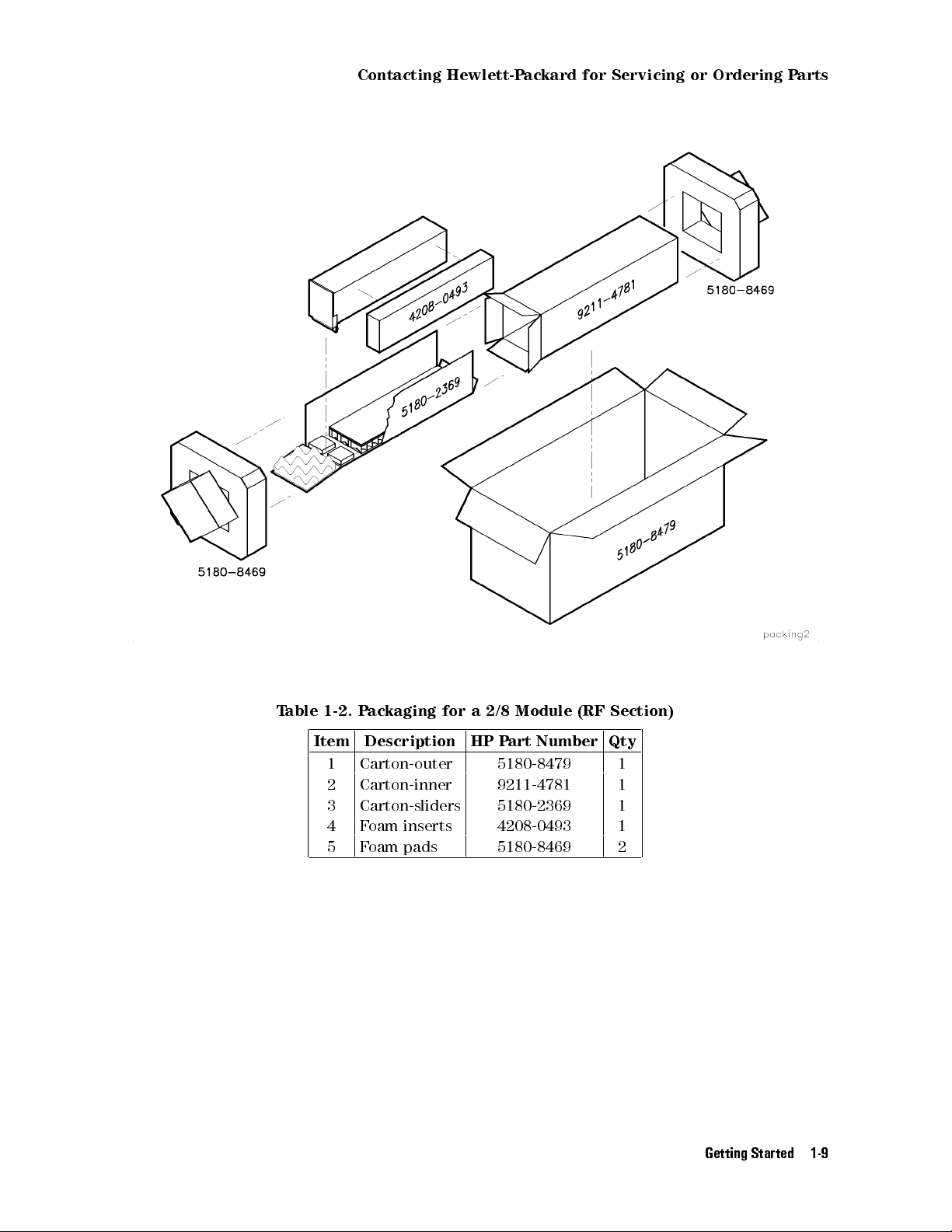
Table 1-2. Packaging for a 2/8 Module (RF Section)
Item Description HP Part Number Qty
1 Carton-outer 5180-8479 1
2 Carton-inner 9211-4781 1
3 Carton-sliders 5180-2369 1
4 Foam inserts 4208-0493 1
5 Foam pads 5180-8469 2
Getting Started 1-9

Installing and Conguring
Module Verication Software
2
Overview
In this chapter you will learn about:
Computer software and hardware requirements
Keyboard compatibility
Installing module verication software, TSCRIPT, and MS TABLE
Purging module verication software, TSCRIPT, and MS TABLE
Test equipment requirements including default models and HP-IB addresses
Editing the
TSCRIPT
le
Specifying storage locations for CAL FACTOR data les and test result data
This chapter prepares you to install and congure the module verication software for your
RF section. You then learn how to load module verication software and how to change
conguration settings by editing a
program to specify dierent storage locations where CAL F
TSCRIPT
le. Finally, you'll learn how to use the
ACTOR data les and test results
MS_TABLE
data can be stored and retrieved from.
Computer Software Requirements
Computer Hardware Requirements
Installing Software and Creating Working Copies
Conguring Module Verication Software
Working with the
Working with the
TSCRIPT
MS_TABLE
File
::::::: ::::::: :::::: ::::::: ::::::: :::::: ::::::: ::::::: ::::::
::::: ::::::: ::::::: :::::: ::::::: ::::::: :::::: ::::::: :::::::
:::::: ::::::: :::::: ::::::: ::::::: :::::: :::::
::::::: ::::::: ::::::: :::::: ::::::: ::::::: :::::: ::::
:::::: ::::::: ::::::: :::::: ::::::: ::::::: :::::: ::::::: ::::::: :
Data File
::::::: ::::::: :::::: ::::::: ::::::: :::::: ::::::: :::::::
2-2
2-3
2-5
2-11
2-16
2-23
Installing and Conguring Module Verication Software 2-1
Computer Software Requirements
To run the module verication software, your computer system must have the following
components:
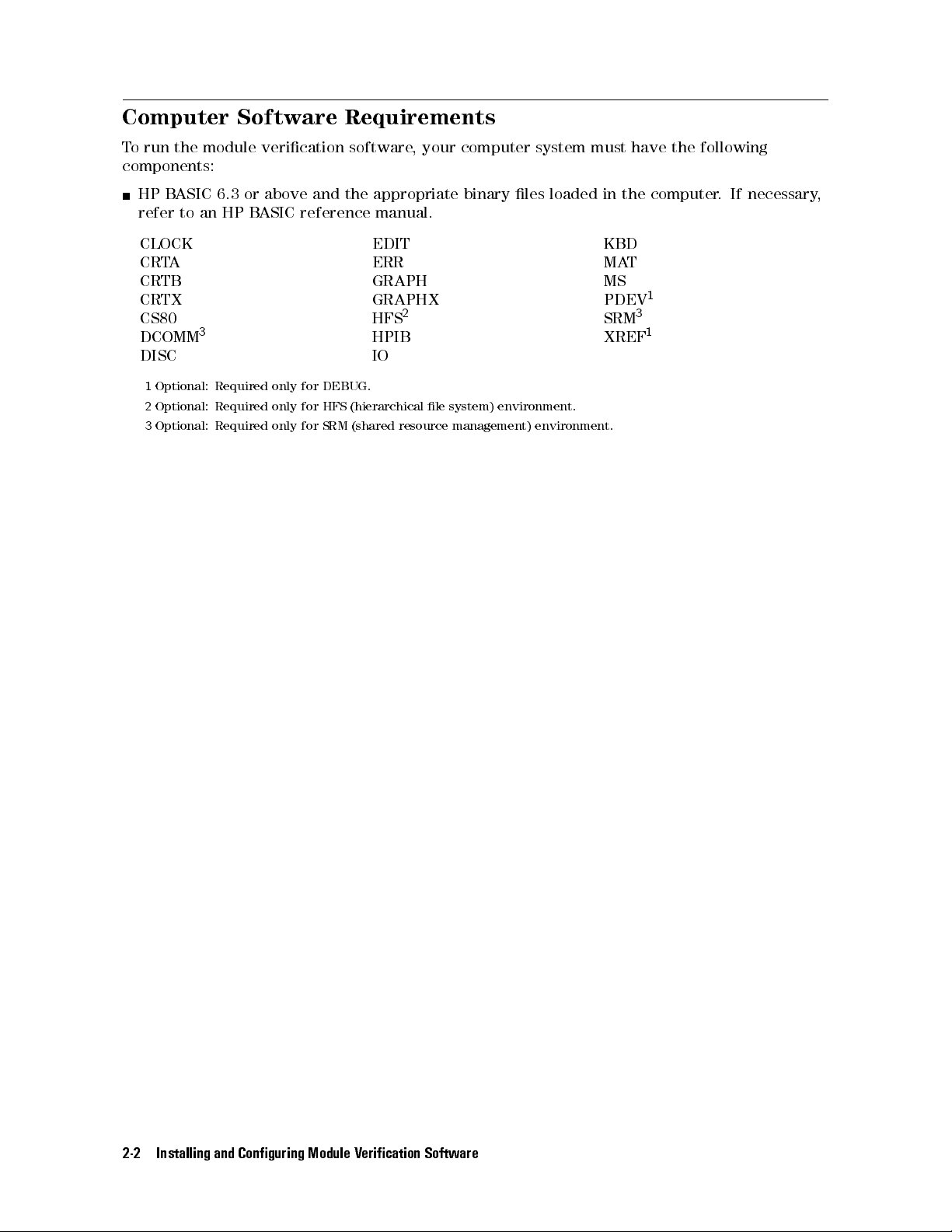
HP BASIC 6.3 or above and the appropriate binary les loaded in the computer. If necessary,
refer to an HP BASIC reference manual.
CLOCK EDIT KBD
CRTA ERR MAT
CRTB GRAPH MS
CRTX GRAPHX PDEV
CS80 HFS
DCOMM
DISC IO
1
2
3
3
Optional: Required only for DEBUG.
Optional: Required only for HFS (hierarchical le system) environment.
Optional: Required only for SRM (shared resource management) environment.
2
HPIB XREF
SRM
1
3
1
2-2 Installing and Conguring Module Verication Software
Computer Hardware Requirements
Computer Hardware Requirements
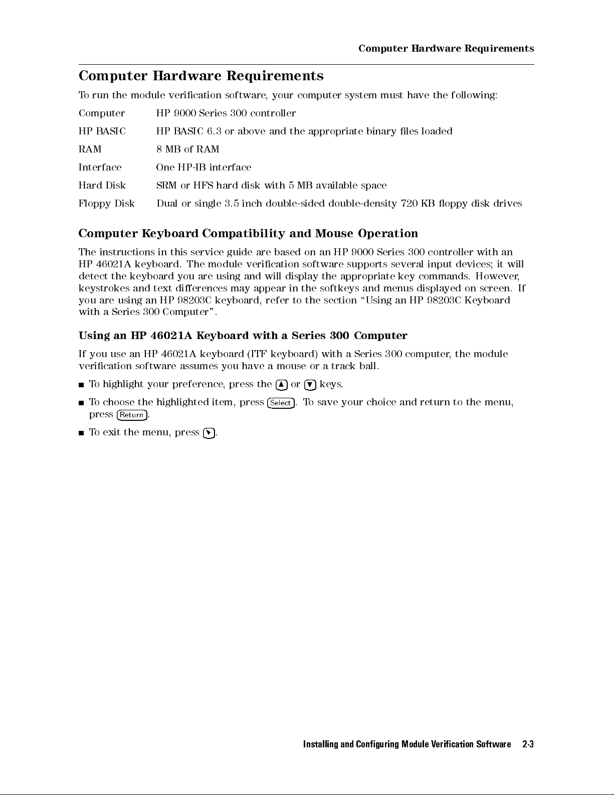
To run the module verication software, your computer system must have the following:
Computer HP 9000 Series 300 controller
HP BASIC HP BASIC 6.3 or above and the appropriate binary les loaded
RAM 8 MB of RAM
Interface One HP-IB interface
Hard Disk SRM or HFS hard disk with 5 MB available space
Floppy Disk Dual or single 3.5 inch double-sided double-density 720 KB oppy disk drives
Computer Keyboard Compatibility and Mouse Operation
The instructions in this service guide are based on an HP 9000 Series 300 controller with an
HP 46021A keyboard. The module verication software supports several input devices; it will
detect the keyboard you are using and will display the appropriate key commands. However,
keystrokes and text dierences may appear in the softkeys and menus displayed on screen. If
you are using an HP 98203C keyboard, refer to the section \Using an HP 98203C Keyboard
with a Series 300 Computer".
Using an HP 46021A Keyboard with a Series 300 Computer
If you use an HP 46021A keyboard (ITF keyboard) with a Series 300 computer
verication software assumes you have a mouse or a track ball.
To highlight your preference, press the
To choose the highlighted item, press
press
4
5
.
Return
To exit the menu, press
4
5
.
4
5or4
5
keys.
9
5
.To save your choice and return to the menu,
4
Select
8
, the module
Installing and Conguring Module Verication Software 2-3
Computer Hardware Requirements
Using an HP 98203C Keyboard with a Series 300 Computer
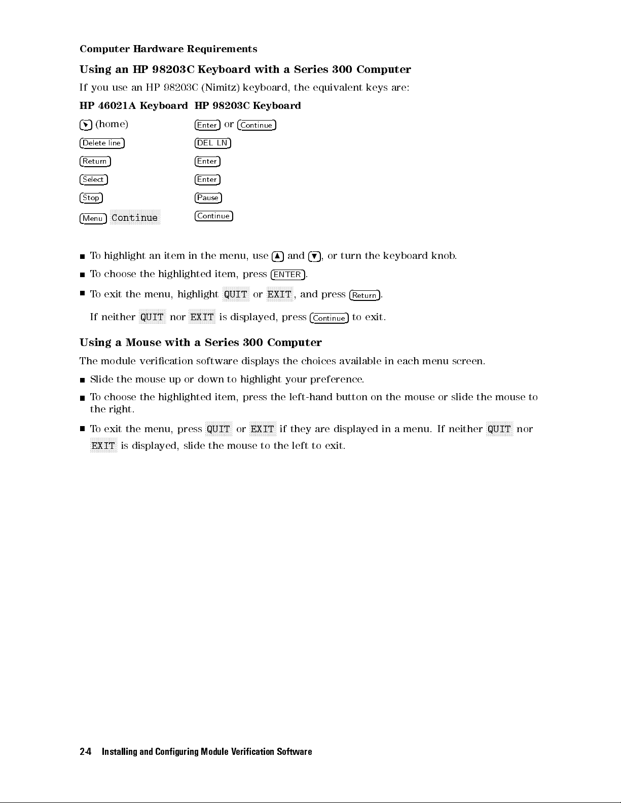
If you use an HP 98203C (Nimitz) keyboard, the equivalent keys are:
HP 46021A Keyboard HP 98203C Keyboard
45
(home)
4
Enter
5or4
Continue
5
4
Delete line
4
Return
4
Select
4
Stop
4
Menu
5 4
5 4
5 4
5 4
NNNNNNNNNNNNNNNNNNNNNNNNNN
5
Continue
4
DEL LN
5
Enter
5
Enter
5
Pause
Continue
5
5
To highlight an item in the menu, use
To choose the highlighted item, press
NNNNNNNNNNNNN
To exit the menu, highlight
If neither
NNNNNNNNNNNNNN
QUIT
nor
NNNNNNNNNNNNNN
EXIT
N
QUIT
or
is displayed, press
485
4
ENTER
NNNNNNNNNNNNN
N
EXIT
and
495
, or turn the keyboard knob.
5
.
, and press
4
Continue
4
Return
5
to exit.
5
.
Using a Mouse with a Series 300 Computer
The module verication software displays the choices available in each menu screen.
Slide the mouse up or down to highlight your preference
.
To choose the highlighted item, press the left-hand button on the mouse or slide the mouse to
the right.
To exit the menu, press
NNNNNNNNNNNNNN
EXIT
is displayed, slide the mouse to the left to exit.
NNNNNNNNNNNNNN
QUIT
or
NNNNNNNNNNNNNN
EXIT
if they are displayed in a menu. If neither
NNNNNNNNNNNNNN
QUIT
nor
2-4 Installing and Conguring Module Verication Software

Installing Software and Creating Working Copies
Installing Software and Creating Working Copies
Overview
In this section you will perform the following steps:
Run INSTALL, from a oppy disk drive or other logical device, and create a
working copy.
The INSTALL program performs the following:
a. Assigns a source disk drive (and optional directory)
b. Assigns a destination disk drive (and optional directory)
c. Copies source les to the destination disk drive (and optional directory)
Module verication software for the RF section consists of the following les:
Executive Disk 1 Executive Disk 2 Tests Disk
OPV UT_SUBS D_8757 DIAGNOSTIC MW_IMGRJT
CSUBS UT_SUBS0 D_3456 EM_IMGRJT EMGAINCAL
CSUBS6 TSCRIPT D_3457 FLAT_50MH AMP_ADJUST
CSUBS63_UX TSCRIPT.MS D_436 LED_CHECK LAST_CONV
CSUBS64_UX TESTINFO D_438 MW_MULT PGA_CALIB
CSUBS7_UX OPTIONS D_8970 MWNOISEFIG 2ND_CONV
INSTALL MUT_INFO D_8566 MW_RESID PS_CHECK
COM ADDR_DEFS D_71200 MW_TOI SEC_STUP
UT_SUBS1 MUT_LIST D_3335 NIFO_RESP YTF_ALIGN
CAL_EDIT UNCERTS D_8662 TUNE_SPAN WIDE_IFO
READ_ME C_TSCRIPT D_8340 SW_REPEAT WBFE_UTIL
DATA_SHEET NET_ANAL D_836x WIFO_300 TEST_SUBS
Disk_1 DVM Disk_2 EMNOISEFIG REPT_SUBS
ET PWR_HARM MS_TABLE
PWR_MTR PWR_HARM_ MS_TAB.MS
RCVR AMP_RANGE EDIT_MSTAB
SOURCE FLATNESS Disk_3
SPEC_ANAL SYS_CAL
Installing and Conguring Module Verication Software 2-5
Installing Software and Creating Working Copies
To create a working copy on an SRM or HFS hard disk
In this section, you will learn how to create a working copy of module verication software on
either an SRM (shared resource manager) or HFS (hierarchical le structure) hard disk drive.
The following steps assume that you have either an SRM or HFS hard disk system and a
3.5 inch double-sided oppy disk drive.
1. Insert
Executive Disk 1
of the module verication software into a 3.5 inch double-sided
oppy disk drive.
2. Assign the MSI (mass storage is:) of the
source disk drive
and press
4
Return
5
.
During a rst-time installation, enter the MSI of the 3.5 inch double-sided oppy disk drive
used in step 1.
(For example,
MSI ":,700,0"
.)
If you have a backup copy stored on a dierent disk drive that you would like to load
instead, enter the full MSVS (mass storage volume specier) of the disk along with any
directory path.
(For example, type
"/OPV9000/70909A_10A:HFS"
3. Type
LOAD "INSTALL",1
This runs the INSTALL program located on
MSI "/OPV9000/70909A_10A:,1400,0"orMSI
.)
and press
4
Return
5
.
Executive Disk 1
.
2-6 Installing and Conguring Module Verication Software
 Loading...