


Installation and Verification Manual
HP 70907A/B
External Mixer Interface
ABCDE
70907-90029
No.
art
P
HP
Printed
in
USA
September
1999

Notice
The information contained in this do cument is sub ject to change without notice.
Hewlett-Packard makes no warrantyofany kind with regard to this material, including,
but not limited to, the implied warranties of merchantability and tness for a particular
purpose. Hewlett-Packard shall not be liable for errors contained herein or for incidental or
consequential damages in connection with the furnishing, performance, or use of this material.
Restricted Rights Legend.
Use, duplication, or disclosure by the U.S. Government is sub ject to restrictions as set forth
in subparagraph (c) (1) (ii) of the Rights in Technical Data and Computer Software clause
at DFARS 252.227-7013 for DOD agencies, and subparagraphs (c) (1) and (c) (2) of the
Commercial Computer Software Restricted Rights clause at FAR 52.227-19 for other agencies.
c
Copyright Hewlett-Packard Company 1990, 1999
All Righ
ermission
p
oun
F
1400
Reserv
ts
is
taingro
Repro
ed.
prohibited,
arkw
P
e
v
duction,
except
Santa
,
y
a
adaptation,
allo
as
Rosa,
under
ed
w
CA
translation
or
cop
the
95403-1799,
yrigh
USA
without
ws.
la
t
prior
written
Certification
Hewlett-Packard Company certies that this product met its published specications at the
time of shipment from the factory. Hewlett-Packard further certies that its calibration
measurements are traceable to the United States National Institute of Standards and
Technology, to the extent allowed by the Institute's calibration facility, and to the calibration
facilities of other International Standards Organization members.
Warranty
This Hewlett-Packard instrument pro duct is warranted against defects in material and
workmanship for a perio d of one year from date of shipment. During the warranty period,
Hewlett-Packard Company will, at its option, either repair or replace products whichproveto
be defective.
For warranty service or repair, this pro duct must be returned to a service facility designated
and
ard
k
Buy
to
by
when
to
ac
w
Ho
er.
Hewlett-P
Hewlett-Pac
erly installed
prop
instrumen
the
of
ev
er,
ac
k
Buy
ard
k
ard
er
for
on
or
t,
Hewlett-P
y
b
Hewlett-P
pay
shall
another
from
Hewlett-P
with
use
instrumen
that
are,
w
soft
ac
kard
ac
shipping
all
coun
ard
k
ac
instrumen
an
rm
or
ard.
k
shall pa
try
arran
w
Hewlett-P
t.
are
w
er
Buy
y shipping
harges,
c
.
ts
will
t
will
shall
that
execute
kard
ac
unin
e
b
prepa
duties,
soft
its
do
terrupted
shipping
y
charges
taxes
and
and
are
w
programming
its
not
es
or
return
to
for
rm
arran
w
error-free.
harges
c
the
ducts
pro
are
w
instructions
that
t
Hewlett-P
to
duct
pro
returned
designated
eration
op
the
Limita
tion
foregoing w
The
tenance
main
misuse,
preparation
site
eration
op
y
b
arrant
Buy
outside
or
not
shall
y
er-supplied
Buy
er,
the
of
maintenance.
apply
vironmen
en
to
soft
defects
are
w
sp
tal
resulting
terfacing,
in
or
from
ecications for
improp
er
unauthorized
the pro
duct, or
inadequate
or
dication
mo
improper
arranty
W
of
NO OTHER WARRANTY IS EXPRESSED OR IMPLIED. HEWLETT-PACKARD
SPECIFICALLY DISCLAIMS THE IMPLIED WARRANTIES OF MERCHANTABILITY
AND FITNESS FOR A PARTICULAR PURPOSE.
Exclusive Remedies
THE REMEDIES
REMEDIES.
HEWLETT-P
PR
VIDED
O
HEREIN
CKARD
A
INDIRECT, SPECIAL, INCIDENT
BASED ON CONTRA
CT, TOR
T, OR
ARE
SHALL
BUYER'S
NOT
SOLE
BE LIABLE
AL, OR CONSEQUENTIAL D
ANY OTHER LEGAL THEOR
AND
DIRECT,
ANY
OR
F
AMAGES, WHETHER
Y.
CLUSIVE
EX
Assistance
available
e
duct
o
Pr
lett-Packar
Hew
any
or
F
maintenanc
pr
d
assistanc
e,
agr
e
ducts.
o
ontact
c
ements
e
your
and
ne
ar
other
est
customer
lett-Packar
Hew
assistanc
Sales
d
e
agr
and
ements
e
Service
ar
Oc
e.
or
for
iii
Safety Symbols
The following safetysymbols are used throughout this manual. Familiarize yourself with each
of the symbols and its meaning b efore operating this instrument.
CAUTION
CAUTION
sign denotes a hazard. It calls attention to a pro cedure
The
which, if not correctly p erformed or adhered to, could result in damage to
or destruction of the product or the user's work. Do not proceed beyond a
WARNING
CAUTION
The
WARNING
sign until the indicated conditions are fully understoo d and met.
sign denotes a hazard. It calls attention to a procedure which,
if not correctly performed or adhered to, could result in injury to the user. Do
not proceed beyond a
WARNING
sign until the indicated conditions are fully
understood and met.
DANGER
DANGER
sign denotes an imminent hazard to people. It warns the reader
The
of a procedure which, if not correctly performed or adhered to, could result
the
until
of
loss
or
injury
in
indicated conditions
life. Do
are fully
not proceed
understood and
beyond
a
met.
ANGER
D
sign
iv

General Safety Considerations
WARNING
ARNING
W
The instructions in this document are for use by qualified personnel only.To
avoid electrical shock, do not perform any servicing unless you are qualified
to do so.
The opening of covers or removal of parts is likely to expose dangerous
voltages. Disconnect the instrument from all voltage sources while it is being
opened.
The power cord is connected to internal capacitors that may remain livefor
five seconds after disconnecting the plug from its power supply.
This is a Safety Class 1 Product (provided with a protective earthing ground
incorporated in the power cord). The mains plug shall only be inserted in a
socket outlet provided with a protective earth contact. Any interruption of the
protective conductor inside or outside of the instrument is likelytomakethe
instrument dangerous. Intentional interruption is prohibited.
same
with
only
fuses
fuse
or
materials
is
continued
For
type
protection
and ratings,
against
(type nA/nV).
hazard,
fire
The use
replace
of other
prohibited.
properly
been
has
it
sure
e
mak
conductor
e
earth
e
on,
contact.
of
the
ac
po
et
sock
a
to
cable
er
w
Before
this instrument
grounded
pro
outlet
through
vided
with
is
protectiv
the
protectiv
switched
sure
e
ac po
correct
conductor,
e earth
primary
its
source.
wer
voltage
interruption
Any
instrument,
the
personal injury
instrument
been
ailure
this
adapted
set
to
Before
has
F
the
of
disconnection
or
.
to
po
ac
the
protectiv
switched
is
oltage
v
the
er
w
input
(grounding)
e
protectiv
the
of
mak
on,
the
of
the
to
to the instrument when the ac power cable is plugged in.
po
or
w
can
er
inside
terminal
could cause
outside
result
circuitry
damage
in
v


Contents
1. General Information
Manual Conventions . . . . . . . . . . . . . . . . . . . . . . . . . . 1-1
Module Description . . . . . . . . . . . . . . . . . . . . . . . . . . 1-2
Firmware Compatibility . . . . . . . . . . . . . . . . . . . . . . . . 1-2
HP 70907A Requirements . . . . . . . . . . . . . . . . . . . . . . 1-2
HP 70907B Requirements . . . . . . . . . . . . . . . . . . . . . . 1-2
LO Firmware Version 860203 or Earlier . . . . . . . . . . . . . . . 1-2
LO Firmware Version From 861015 to 880901 . . . . . . . . . . . . . 1-2
Module Options . . . . . . . . . . . . . . . . . . . . . . . . . . . 1-3
HP 70907A . . . . . . . . . . . . . . . . . . . . . . . . . . . . 1-3
HP 70907B
Considerations
y
Safet
ered
v
Co
dules
Mo
b
Num
Serial
ection
Initial
Accessories
F
Electrostatic
Returning Instruments for Service . . . . . . . . . . . . . . . . . . . . 1-13
Sales and Service Oces . . . . . . . . . . . . . . . . . . . . . . . . 1-15
Insp
.
Rear-P
and
t-
ron
Status
F
Mo
Rear-P
Reducing
Static-Safe Accessories . . . . . . . . . . . . . . . . . . . . . . . . 1-12
and
anel
t-P
ron
dule Latc
anel
Disc
ESD Damage
PC Board
Test Equipment. . . . . . . . . . . . . . . . . . . . . . . . . . 1-11
. .
b
ers
. .
anel
Error
Inputs
h
Inputs
harge
Assem
. .
. .
.
Man
y
.
.
.
.
.
.
.
.
.
F
LEDs
and
.
.
.
and
Information
blies
.
.
.
.
.
.
ual
.
.
.
.
.
.
.
.
.
eatures
.
.
Outputs .
.
.
.
Outputs
. .
Electronic
and
.
.
.
.
. .
.
.
.
.
. .
. .
. .
. .
.
.
.
.
.
.
.
.
.
.
.
.
.
.
.
.
. .
. .
. .
. .
.
.
.
.
.
.
.
.
.
.
.
.
.
.
.
.
. .
. .
.
.
.
.
.
.
.
.
.
.
.
.
.
.
.
.
.
.
.
.
.
.
.
. .
. .
.
.
.
.
.
.
.
.
.
.
.
.
.
.
.
.
.
.
.
.
.
.
.
.
. .
.
.
.
.
.
.
.
.
.
.
.
.
.
.
.
.
.
.
.
.
.
.
.
. .
.
.
.
.
.
.
.
.
.
.
.
.
.
.
.
.
.
.
.
.
.
.
.
. .
.
.
.
.
.
.
.
.
.
.
.
.
.
.
.
.
.
.
.
.
.
.
.
.
.
.
.
. .
. .
.
.
.
.
.
.
.
.
.
.
.
.
.
.
.
.
.
. .
. .
.
.
.
.
.
.
.
.
.
.
.
.
.
.
.
.
.
.
.
.
.
. .
. .
.
.
.
.
.
.
.
.
.
.
.
.
.
.
.
.
.
.
.
.
.
.
.
. .
. 1-10
.
.
.
.
.
.
.
.
.
.
ts
onen
Comp
1-3
1-3
1-4
1-4
1-4
1-5
1-6
1-6
1-6
1-6
1-8
1-10
1-10
Installation
2.
.
Addressing
Determining the HP-MSIB Address
Setting the HP-MSIB Address Switc
Installing the Mo dule in the Mainframe
Connecting the Rear-P
Checking Mo dule Operation
Examining the Front-Panel LEDs . . . . . . . . . . . . . . . . . . . 2-7
Checking for Error Messages . . . . . . . . . . . . . . . . . . . . . 2-7
the
dule
Mo
.
anel Cables
.
. .
.
.
.
.
.
.
.
.
.
.
.
. .
.
.
. . . . . . . . . . . . . . . . . . 2-2
hes . . . . . .
. . . . . . . . . . . . . . . . . 2-4
. . . . . . .
. . . . . . . . . . . . . . . . . . .
. . . . . . . . . . 2-3
. . . . . . . . . . . . 2-5
.
.
.
.
. . . 2-7
Contents-1
2-2

3. Specications
HP 70907A Mo dule Sp ecications and Characteristics . . . . . . . . . . . 3-2
Front-Panel Inputs and Outputs . . . . . . . . . . . . . . . . . . . 3-2
Rear-Panel Inputs and Outputs . . . . . . . . . . . . . . . . . . . . 3-2
LO IN . . . . . . . . . . . . . . . . . . . . . . . . . . . . . . 3-2
LO OUT . . . . . . . . . . . . . . . . . . . . . . . . . . . . . 3-2
TUNE SPAN . . . . . . . . . . . . . . . . . . . . . . . . . . . 3-2
321.4 MHz OUT . . . . . . . . . . . . . . . . . . . . . . . . . 3-2
300 MHz OUT . . . . . . . . . . . . . . . . . . . . . . . . . . 3-2
300 MHz IN . . . . . . . . . . . . . . . . . . . . . . . . . . . 3-2
21.4 MHz OUT . . . . . . . . . . . . . . . . . . . . . . . . . . 3-3
21.4 MHz IN . . . . . . . . . . . . . . . . . . . . . . . . . . . 3-3
General Specications and Characteristics . . . . . . . . . . . . . . . 3-3
HP 70907B Mo dule Sp ecications and Characteristics . . . . . . . . . . . 3-4
Front-Panel Inputs and Outputs . . . . . . . . . . . . . . . . . . . 3-4
Rear-Panel Inputs and Outputs . . . . . . . . . . . . . . . . . . . . 3-4
LO IN . . . . . . . . . . . . . . . . . . . . . . . . . . . . . . 3-4
LO OUT . . . . . . . . . . . . . . . . . . . . . . . . . . . . . 3-4
. .
. .
.
.
.
.
.
.
.
.
.
.
.
.
.
.
.
.
.
.
.
OUT
IN
. .
.
. .
. .
. .
. .
.
.
.
.
.
.
.
.
.
.
.
.
.
.
.
.
.
.
.
.
.
.
.
.
.
.
. .
. .
.
.
.
.
.
.
.
.
.
.
.
.
.
.
.
.
.
.
.
.
.
.
.
.
.
.
.
.
.
. .
. .
.
.
.
. .
. .
.
.
.
.
.
.
.
.
.
.
.
.
.
.
.
.
.
.
.
.
.
.
.
.
.
.
.
.
.
. .
.
.
.
.
.
.
.
.
.
.
.
.
.
.
.
.
.
.
.
.
.
. .
.
.
.
.
.
.
Characteristics
and
.
TUNE SP
321.4
300
300
21.4
21.4
General
AN .
MHz
OUT
MHz
IN
MHz
MHz OUT
MHz
ecications
Sp
. 3-4
.
.
.
.
.
.
3-4
3-4
3-4
3-5
3-5
3-5
4.
5.
erication
V
roublesho
T
t-P
ron
F
Error
Usage/Op
Hardw
oting
LEDs
anel
Messages
erating Errors
W
are
.
.
.
arning
.
.
.
.
Errors
.
.
.
.
.
.
.
.
.
.
.
.
.
. .
. .
.
.
.
.
.
.
.
.
.
.
.
.
.
.
.
.
.
.
.
.
.
.
.
.
.
. .
. .
.
.
. .
.
.
.
.
.
.
.
.
.
.
.
.
.
.
.
.
.
. .
. .
.
.
. .
. .
. .
.
.
.
.
.
.
.
.
.
.
.
.
.
.
Hardware Broken Errors . . . . . . . . . . . . . . . . . . . . . . . 5-2
Index
5-1
5-1
5-2
5-2
Contents-2
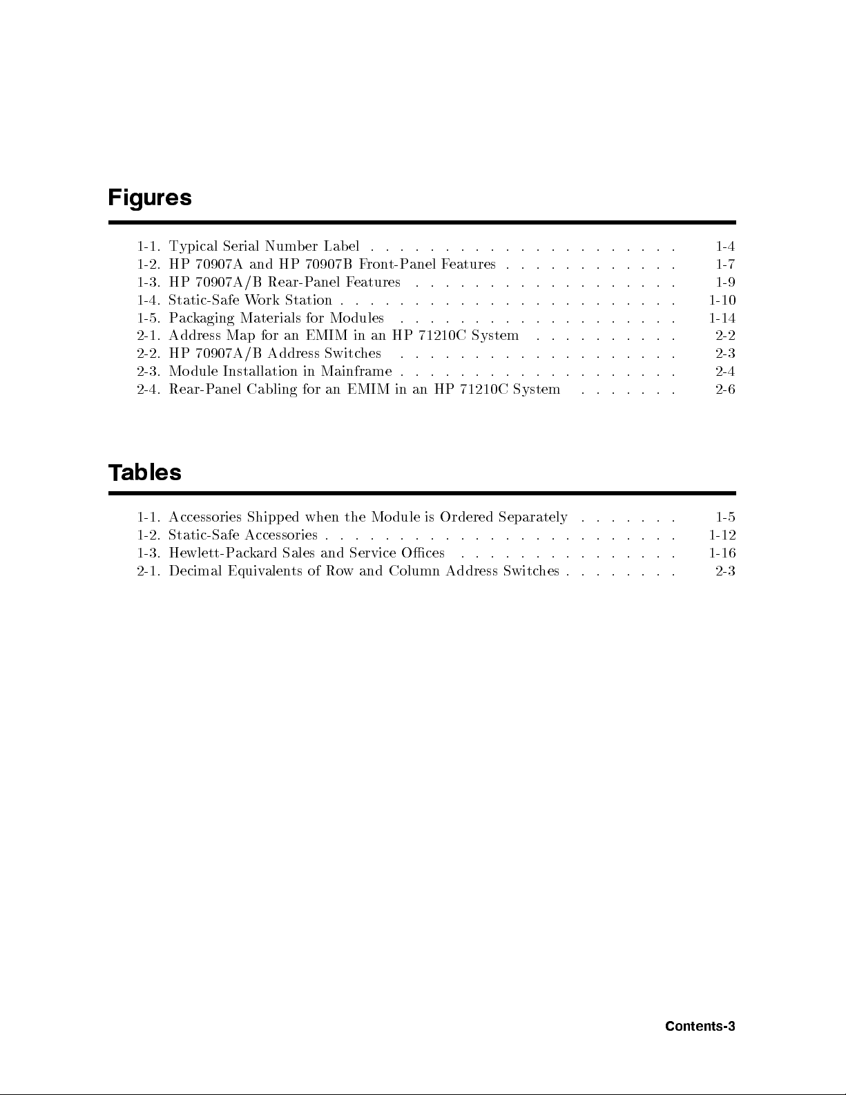
Figures
1-1. Typical Serial Number Label . . . . . . . . . . . . . . . . . . . . . 1-4
1-2. HP 70907A and HP 70907B Front-Panel Features . . . . . . . . . . . . 1-7
1-3. HP 70907A/B Rear-Panel Features . . . . . . . . . . . . . . . . . . 1-9
1-4. Static-Safe Work Station . . . . . . . . . . . . . . . . . . . . . . . 1-10
1-5. Packaging Materials for Mo dules . . . . . . . . . . . . . . . . . . . 1-14
2-1. Address Map for an EMIM in an HP 71210C System . . . . . . . . . . 2-2
2-2. HP 70907A/B Address Switches . . . . . . . . . . . . . . . . . . . 2-3
2-3. Module Installation in Mainframe . . . . . . . . . . . . . . . . . . . 2-4
2-4. Rear-Panel Cabling for an EMIM in an HP 71210C System . . . . . . . 2-6
ables
T
1-1.
1-2.
1-3.
2-1.
Accessories
Static-Safe
Hewlett-P
Decimal
Equiv
ed
Shipp
Accessories
Sales and
ard
k
ac
alen
ts
when
.
Ro
of
the
.
.
Service
and
w
dule
Mo
.
.
Column
is
.
.
.
Oces
Ordered
. .
.
.
.
Address
Separately
.
.
.
.
.
.
.
.
hes
Switc
.
.
.
.
.
.
.
.
.
.
.
.
.
.
.
.
.
.
.
.
.
.
.
.
.
.
.
.
.
.
.
.
.
1-5
1-12
1-16
2-3
Contents-3

1
General Information
The
HP 70907A/B External Mixer Interface Instal lation and Verication Manual
contains
information needed to install the HP 70907A/B External Mixer Interface mo dule (EMIM)
into an HP 70000 Series system and then check basic mo dule operation. For information on
installing and verifying HP 70000 Mo dular Measurement Systems, refer to the Installation and
Verication Manual for the system master (for example, HP 70900B Local Oscillator).
This manual contains the following vechapters:
Chapter 1, \General Information," describes the mo dule and its accessories, gives
electrostatic discharge and packaging information, and lists Hewlett-Packard Sales and
Service Oces.
in
dule
mo
that
HP
Man
the
apply to
70907A/B
the
for
ual
Chapter 2,
70000
HP
an
Chapter
the
added to
is
system
3,
70907A/B.
HP
master.)
\Installation," pro
Measuremen
dular
Mo
ecications,"
\Sp
(System
cumen
do
system
a
are
vides information
System.
t
sp
dule
mo
lists
in
that will
the
ecications
sp
ted
for conguring
ecications
be
Installation
and
mo
c
died
and
installing
and
haracteristics
the
when
erication
V
the
out
the
most
error
ab
probable
co
des
Chapter
ecications.
sp
4,
Chapter 5,
status
HP
and
70907A/B
erication,"
\V
roublesho
\T
LEDs'
error
dule.
mo
con
oting,"
ting,
ligh
tains
explains
and
information
the
lists
Manual Conventions
The following descriptions are used throughout this manual:
the
in
ysically
ph
Keys
.
Key
Softkeys, k
.
on an
..
.
.
.
.
.
eys dened b
Softkey ............
ext that appears on the displa
T
instrumen
.
.
.
.
.
.
.
.
ysoftw
.........................
Screen text . . . . . . . . . . . .
represen
are
t
.
.
.
.
.
.
..
.
.
.
are or rm
y screen is represen
.........................
ted
.
.
.
.
.
.
.
.
..
.
.
.
.
ware, are represen
..................
ted in the follo
.
the
of
generated b
e
b
ay:
w
.
.
.
.
.
to v
fron
.
.
..
tests
causes
that
follo
.
.
wing
..
needed
can
.
.
.
ted in the following w
wing w
............
ay:
screen text
the
erify
t-panel
y the
4
.
.
.
KEY
ay:
NNNNNNNNN
NNNNNNNNNNNNNN
softkey
5
General
Information
1-1
Module Description
Both the HP 70907A and the HP 70907B External Mixer Interface mo dules (EMIMs)
are 1/8-width mo dules designed to plug into HP 70000 Mo dular Measurement System
mainframes. The mo dules are slaves controlled by an HP 70000 Mo dular Measurement
System master elementsuch as the HP 70900B Lo cal Oscillator.
Both EMIMs allow HP 70000 Mo dular Measurement systems to operate with the HP 11970
Series of external mixers. The HP 70907B also allows operation with the HP 11974 Series of
preselected millimeter-wavefront ends. At turn on, the system master sets the HP 70907B
default state to
preselector-magnetics in an HP 11974 Series front end. If the HP 70907B is used with an
external mixer from the HP 11970 Series,
NNNNNNNNNNNNNNNNNNNNNNNNNNNNN
PRESEL ON
, resulting in a sweeptime that is slow enough for the internal
NNNNNNNNNNNNNNNNNNNNNNNNNNNNNNNN
PRESEL OFF
can b e selected to tell the system
master to sweep faster.
Firmware Compatibility
HP
or
F
HP
rm
um
n
HP
For
HP
Firmware
LO
70907A
the
70900
are
w
ber
70907B
the
70900
Requirements
70907A
HP
oscillator
cal
lo
850730,
ersion
v
is
70900-60137).
Requirements
70907B
HP
oscillator
cal
lo
Version
function
to
(LO)
function
to
(LO)
860203 or
a
prop
m
con
prop
m
Earlier
erly
ha
ust
troller b
erly
ha
ust
an
in
rm
a
e
v
oard/rm
an
in
rm
a
e
v
HP
w
HP
w
70000
are v
w
70000
are
dular
Mo
ersion of
are-upgrade
dular
Mo
ersion of
v
Measuremen
860203
kit
or
can
Measuremen
890606 or
e
b
later.
later.
System,
t
If
ordered
System,
t
the
(HP
LO
part
If the HP 70900 lo cal oscillator rmware version is 860203 or earlier, an LO controller
board/rmware-upgrade kit (HP part number 70900-60137) can b e ordered. If HP 70907B
Option 098 is ordered, this controller board/rmware-upgrade kit is included.
880901
L
If
O
the
Firmw
HP
ersion From
V
are
70900
lo
cal
861015
oscillator
rmware-upgrade kit (HP part n
Option 099 is ordered, this rm
to
LO
rmw
are
ersion
v
is
from
861015
880901,
to
an
umber 70900-60138) can be ordered. If HP 70907B
ware-upgrade kit is
included.
the
the
1-2
General
Information
Module Options
HP 70907A
The HP 70907A has the following mo dule options:
Option 910
Option 915
This option adds another
and Verication Manual
HP 70907A/B External Mixer Interface Instal lation
.
This option adds the module service documentation and mo dule verication
software.
HP 70907B
The HP 70907B has the following mo dule options:
Option 098
This option adds the LO controller board/rmware-upgrade kit. Refer to
\Firmware Compatibility" above for information ab out which LO rmware
versions are needed for compatibility with the 70907B mo dule.
are-upgrade
w
rm
LO
the
Option
Option
Option
099
910
915
option
This
Compatibilit
needed for
option
This
eric
V
and
option
This
are.
w
soft
adds
efor
v
o
ab
y"
compatibility
another
adds
Manual
ation
module
the
adds
information ab
the
with
70907A/B
HP
.
service
70907B
cumen
do
kit.
out whic
dule.
mo
External
tation
Refer
hLO
Mixer
to \Firm
rm
Interfac
mo
and
w
dule
ware
are
ersions
v
Instal
e
erication
v
are
lation
Safety
Before
and
Considerations
erating this
op
instructions
the safet
y
module,
in
familiarize y
ual.
man
this
ourself with
dule
mo
This
an
y
has
safet
een
b
markings
y
man
on
ufactured
the
and
mo
dule
tested
according to international safety standards. However, to ensure safe op eration of the module
and p ersonal safety of the user and service personnel, the cautions and warnings in this
manual must b e followed. Refer to the summary of safety considerations at the frontofthis
manual.
General
Information
1-3
Modules Covered by Manual
Serial Numbers
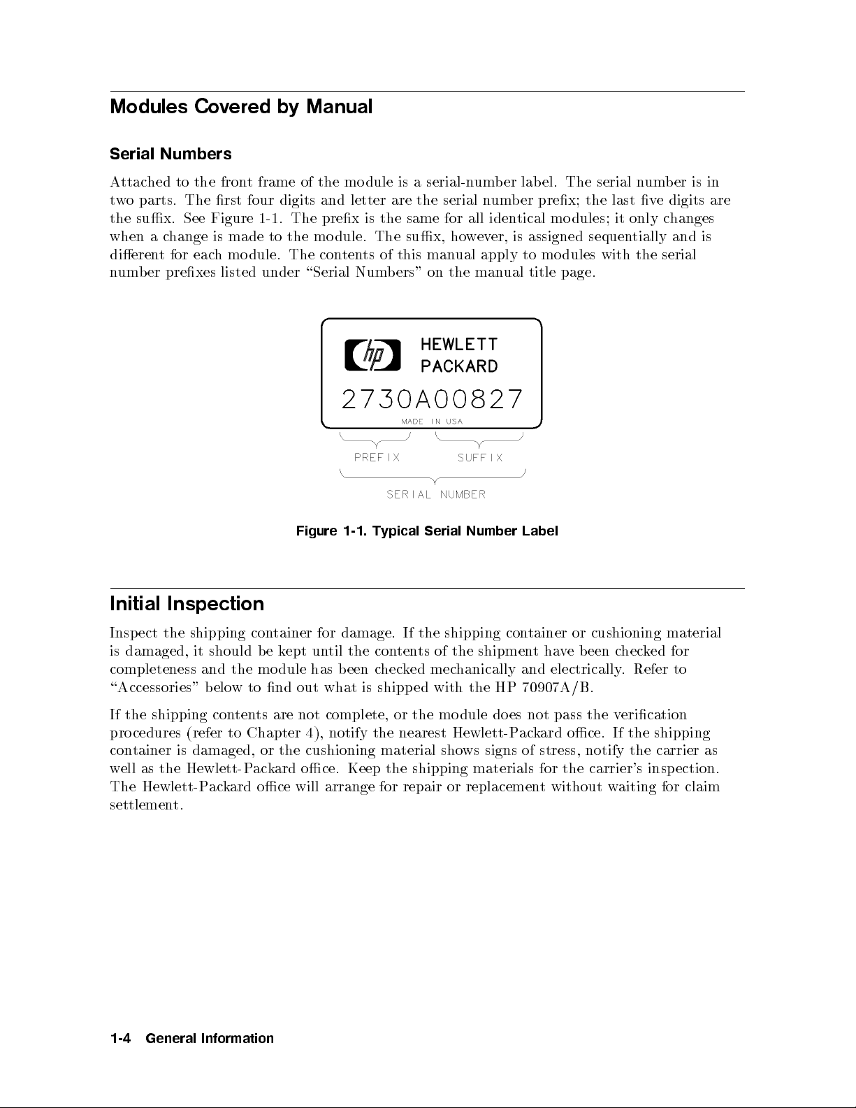
Attached to the front frame of the mo dule is a serial-number lab el. The serial number is in
two parts. The rst four digits and letter are the serial number prex; the last ve digits are
the sux. See Figure 1-1. The prex is the same for all identical modules; it only changes
when a change is made to the mo dule. The sux, however, is assigned sequentially and is
dierent for each mo dule. The contents of this manual apply to modules with the serial
number prexes listed under \Serial Numbers" on the manual title page.
Label
con
tainer
or
ve
ha
t
and electrically
cushioning
chec
been
. Refer
ked
material
for
to
Initial
Insp
Inspection
the
ect
is damaged,
completeness
shipping con
the
b
mo
should
it
and
Figure
tainer for
ept
k
e
dule
un
has
1-1.
damage.
the
til
een
b
Typical
If
ten
con
k
hec
c
Serial
shipping
the
the
of
ts
mechanically
ed
Number
shipmen
\Accessories" below to nd out what is shipp ed with the HP 70907A/B.
If the shipping contents are not complete, or the mo dule do es not pass the verication
procedures (refer to Chapter 4), notify the nearest Hewlett-Packard oce. If the shipping
container is damaged, or the cushioning material shows signs of stress, notify the carrier as
ection.
aiting for
w
insp
claim
the
as
ell
w
Hewlett-P
The
settlemen
Hewlett-P
ack
t.
ard
k
ac
oce
ard
oce.
will
Keep the
arrange
for
shipping
repair
materials
replacemen
or
the
for
without
t
carrier's
1-4
General
Information
 Loading...