


Service Guide
HP 70902A
IF Section
ABCDE
HP Part No. 70902-90079
Printed in USA December 1992

Notice.
The information contained in this document is sub ject to change without notice.
Hewlett-Packard makes no warrantyofany kind with regard to this material, including
but not limited to, the implied warranties of merchantability and tness for a particular
purpose. Hewlett-Packard shall not be liable for errors contained herein or for incidental or
consequential damages in connection with the furnishing, p erformance, or use of this material.
c
Copyright Hewlett-Packard Company 1988, 1992
All Rights Reserved. Reproduction, adaptation, or translation without prior written
permission is prohibited, except as allow
1212 Valley House Drive, Rohnert Park, CA 94928-4999, USA
ed under the copyrightlaws.

Certification
Hewlett-Packard Company certies that this product met its published specications at the
time of shipment from the factory. Hewlett-Packard further certies that its calibration
measurements are traceable to the United States National Institute of Standards and
Technology, to the extent allowed by the Institute's calibration facility, and to the calibration
facilities of other International Standards Organization members.
Warranty
This Hewlett-Packard instrument product is warranted against defects in material and
workmanship for a p eriod of one year from date of shipment. During the warranty period,
Hewlett-Packard Company will, at its option, either repair or replace products which proveto
be defective.
For warranty service or repair, this product must be returned to a service facilit y designated
by Hewlett-Packard. Buyer shall prepay shipping charges to Hewlett-Packard and
Hewlett-Packard shall pay shipping charges to return the product to Buyer. However, Buyer
shall pay all shipping charges, duties, and taxes for pro ducts returned to Hewlett-P
ackard
from another country.
Hewlett-Packard warrants that its software and rmware designated by Hewlett-Packard for
use with an instrument will execute its programming instructions when properly installed on
that instrument. Hewlett-Packard does not warrant that the operation of the instrument, or
software, or rmware will be uninterrupted or error-free.
Limitation of Warranty
The foregoing warranty shall not apply to defects resulting from improp er or inadequate
maintenance by Buyer, Buyer-supplied software or interfacing, unauthorized modication or
misuse, operation outside of the environmental specications for the product, or improper
site preparation or maintenance.
NO OTHER WARRANTY IS EXPRESSED OR IMPLIED. HEWLETT-PACKARD
SPECIFICALLY DISCLAIMS THE IMPLIED WARRANTIES OF MERCHANTABILITY
AND FITNESS FOR A PARTICULAR PURPOSE.
Exclusive Remedies
THE REMEDIES PROVIDED HEREIN ARE BUYER'S SOLE AND EXCLUSIVE
REMEDIES. HEWLETT-PACKARD SHALL NOT BE LIABLE FOR ANY DIRECT,
INDIRECT, SPECIAL, INCIDENTAL, OR CONSEQUENTIAL DAMAGES, WHETHER
BASED ON CONTRACT, TORT, OR ANY OTHER LEGAL THEORY.
Assistance
Product maintenance agreements and other customer assistance agreements are available for
Hewlett-Packardproducts.
For any assistance, contact your nearest Hewlett-Packard Sales and Service Oce.
iii
Safety Notes
The following safety notes are used throughout this manual. Familiarize yourself with eachof
the notes and its meaning before operating this instrument.
Caution
Warning
Instruction
Manual
L
Caution
correctly performed or adhered to, could result in damage to or destruction
of the instrument. Do not pro ceed beyond a
conditions are fully understo od and met.
Warning
correctly performed or adhered to, could result in injury or loss of life. Do
not proceed beyond a
understood and met.
The
necessary for the user to refer to the instructions in the man
denotes a hazard. It calls attention to a procedure that, if not
caution
denotes a hazard. It calls attention to a procedure which, if not
instruction manual
warning
symbol. The product is marked with this symbol when it is
note until the indicated conditions are fully
sign until the indicated
ual.
iv

General Safety Considerations
Warning
Warning
Caution
Before this instrument is switchedon
through the protective conductor of the ac power cable to a socket outlet
provided with protective earth contact.
Any interruption of the protective (grounding) conductor, inside or outside
the instrument, or disconnection of the protective earth terminal can result in
personal injury.
There are many points in the instrument which can, if contacted, cause personal
injury. Be extremely careful.
Any adjustments or service procedures that require operation of the instrument
with protectivecovers removed should be performed only by trained service
personnel.
Before this instrument is switche
has been adapted to the voltage of the ac power source.
Failure to set the ac power input to the correct voltage could cause damage to
the instrument when the ac p ower cable is plugged in.
, make sure it has been properly grounded
d on,
make sure its primary po
wer circuitry
v

Servicing at a Glance
vi

The HP 70902A IF section is an IF module that is used in HP 70000 Series mo dular spectrum
analyzer systems. A standard mo dular sp ectrum analyzer system includes a mainframe with
an RF section, IF section , lo cal oscillator, an optional display, and an optional precision
frequency reference.
Documentation and software supplied
This service guide is part of an Option 915 package which includes:
HP 70902A Service Guide
HP 70902A Component Level Information Packages
Five disks containing mo dule verication software.
Tools and equipment needed
Before servicing, refer to Chapter 2 for a list of the tools and equipment that may be needed
during servicing.
Antistatic precautions
Electrical components are easily damaged by small amounts of static electricity. If possible,
work at a static-safe work station. For further information, refer to \Electrostatic Discharge
Information" in Chapter 2.
vii

In This Book
This bo ok is part of an Option 915 documentation package which consists of a service guide,
a component-level information packages manual, and software disks that contain mo dule
verication software.
It describes all of the service procedures necessary to test, adjust, troubleshoot, and repair
an HP 70902A IF section in an HP 70000 Series modular spectrum analyzer system. Each
module in the HP 70000 Series mo dular spectrum analyzer system has its own service guide.
For further information related to the servicing of additional and alternate modules that can
be used in this system, refer to that module's service guide.
Service Guide
Chapter 1 answers the questions \What is service?" and \When is service needed?" It then
describes the procedures used to return your HP 70902A IF section to Hewlett-Packard for
servicing.
Chapter 2 contains a list of recommended test equipment, a listing of a general service kit
for HP 70000 modular measurement system mo dules, do cumentation on the HP 70902A
Option K01 IF section, and information on electrostatic disc
harge (ESD).
Chapter 3 contains information needed to use module verication software.
Chapter 4 contains information on the tests used to verify mo dule op eration.
Chapter 5 contains information about the pro cedures needed to adjust the mo dule after a
repair.
Chapter 6 contains mo dule-level troublesho oting pro cedures, error-code denitions, and
block diagrams.
Chapter 7 contains instructions for removal and replacement of all major assemblies.
Chapter 8 contains information needed to order mechanical parts and replacement board or
cable assemblies for the module.
Chapter 9 contains gures identifying all major assemblies and cables.
An index is also added at the end of this service guide to aid the user in nding key items
of interest.
Component-Level Information Packages
The component-level information packages manual contains packets of comp onent-level
repair information for each HP 70902A IF section board assembly that has eld-replaceable
parts. Each packet includes the parts list, comp onent-location drawing, and schematics for
a specic board-assembly part number. This chapter also contains a table cross-referencing
board-assembly version and mo dule serial prex.
Before you begin servicing
,you must b ecome familiar with mo dule verication software. For
information on how to use mo dule verication software, refer to Chapter 3.
viii

Contents
1. Getting Started
What is servicing? . . . . . . . . . . . . . . . . . . . . . . . . . . 1-2
When is servicing needed? . . . . . . . . . . . . . . . . . . . . . . . 1-2
If you want Hewlett-Packard to service your HP 70902A IF section . . . . . 1-3
Determining your HP 70902A IF section's serial number . . . . . . . . . 1-3
Returning your HP 70902A IF section for service . . . . . . . . . . . . 1-4
2. Recommended Test Equipment
Service Kit . . . . . . . . . . . . . . . . . . . . . . . . . . . . . . 2-8
21.4 MHz Notch-Filter Do cumentation . . . . . . . . . . . . . . . . . . 2-9
Electrostatic Discharge Information . . . . . . . . . . . . . . . . . . . 2-11
Reducing ESD Damage . . . . . . . . . . . . . . . . . . . . . . . 2-12
PC Board Assemblies and Electronic Comp onents . . . . . . . . . . . 2-12
Test Equipment. . . . . . . . . . . . . . . . . . . . . . . . . . 2-12
Static-Safe Accessories . . . . . . . . . . . . . . . . . . . . . . . . 2-13
3. Module Verication Software
General Information . . . . . . . . . . . . . . . . . . . . . . . . . . 3-1
Computer Compatibility. . . . . . . . . . . . . . . . . . . . . . . . 3-2
Computer Language Compatibility . . . . . . . . . . . . . . . . . . 3-2
Printer Compatibility . . . . . . . . . . . . . . . . . . . . . . . . 3-2
Typographic Conventions . . . . . . . . . . . . . . . . . . . . . . . 3-3
Conguring the Hardware . . . . . . . . . . . . . . . . . . . . . . . 3-4
Procedure . . . . . . . . . . . . . . . . . . . . . . . . . . . . . 3-4
Installing Module Verication Software . . . . . . . . . . . . . . . . . 3-5
Software Version . . . . . . . . . . . . . . . . . . . . . . . . . . 3-5
Procedure . . . . . . . . . . . . . . . . . . . . . . . . . . . . 3-5
Module Verication Software Overview . . . . . . . . . . . . . . . . . 3-7
Testing Multiple Mo dules . . . . . . . . . . . . . . . . . . . . . . 3-7
Error Messages or Warnings Dened . . . . . . . . . . . . . . . . . 3-7
Final Tests Dened . . . . . . . . . . . . . . . . . . . . . . . . . 3-7
Single Tests Dened . . . . . . . . . . . . . . . . . . . . . . . . . 3-8
Printing Test Results . . . . . . . . . . . . . . . . . . . . . . . . 3-8
Menus . . . . . . . . . . . . . . . . . . . . . . . . . . . . . . . . 3-9
Menu Structure . . . . . . . . . . . . . . . . . . . . . . . . . . . 3-9
Edit and Command Screen Menus . . . . . . . . . . . . . . . . . . 3-9
Edit Screen Menus . . . . . . . . . . . . . . . . . . . . . . . . 3-9
Command Screen Menus . . . . . . . . . . . . . . . . . . . . . . 3-10
Cursor Keys and Menu Selections . . . . . . . . . . . . . . . . . . 3-11
Main Menu . . . . . . . . . . . . . . . . . . . . . . . . . . . . 3-11
Main Menu Softkeys . . . . . . . . . . . . . . . . . . . . . . . . 3-11
Mass Storage Menu . . . . . . . . . . . . . . . . . . . . . . . . . 3-11
Contents-1

Mass Storage Menu Edit Screen . . . . . . . . . . . . . . . . . . 3-12
Mass Storage Menu Command Screen . . . . . . . . . . . . . . . . 3-12
Parameter Menu . . . . . . . . . . . . . . . . . . . . . . . . . . 3-13
Parameter Menu Edit Screen . . . . . . . . . . . . . . . . . . . . 3-13
Parameter Menu Command Screen . . . . . . . . . . . . . . . . . 3-14
Equipment Menu . . . . . . . . . . . . . . . . . . . . . . . . . . 3-14
Equipment Menu Edit Screen . . . . . . . . . . . . . . . . . . . . 3-14
Equipment Menu Command Screen . . . . . . . . . . . . . . . . . 3-15
Edit Calibration Data . . . . . . . . . . . . . . . . . . . . . . . . 3-16
Edit Calibration Data Edit Screen . . . . . . . . . . . . . . . . . 3-16
Edit Calibration Data Command Screen . . . . . . . . . . . . . . . 3-17
HP-MSIB Address Menu. . . . . . . . . . . . . . . . . . . . . . . 3-17
Test Menu . . . . . . . . . . . . . . . . . . . . . . . . . . . . . 3-17
Test Menu Command Screen . . . . . . . . . . . . . . . . . . . . 3-19
Error and Status Messages . . . . . . . . . . . . . . . . . . . . . . . 3-25
4. Module Verication Tests
Preferred Frequency-Reference Connections . . . . . . . . . . . . . . . 4-2
1. FrontPanel LED Check. . . . . . . . . . . . . . . . . . . . . . 4-4
2. Diagnostic Detectors Check . . . . . . . . . . . . . . . . . . . . 4-5
3. 18.4 MHz Oscillator StabilityTest . . . . . . . . . . . . . . . . . 4-7
4. DUT Calibration . . . . . . . . . . . . . . . . . . . . . . . . . 4-9
5. Average Noise Test . . . . . . . . . . . . . . . . . . . . . . . . 4-12
6. Corrected Sensitivity Test . . . . . . . . . . . . . . . . . . . . . 4-14
7. Third-Order Intercept Test . . . . . . . . . . . . . . . . . . . . 4-16
8. Spurious Responses Test . . . . . . . . . . . . . . . . . . . . . 4-18
9. Resolution Bandwidths Test . . . . . . . . . . . . . . . . . . . . 4-20
10. Video Bandwidths Test . . . . . . . . . . . . . . . . . . . . . 4-23
11. Module Gain Test . . . . . . . . . . . . . . . . . . . . . . . . 4-25
12. Calibration Attenuator Test . . . . . . . . . . . . . . . . . . . 4-27
13. Corrected Module FidelityTest . . . . . . . . . . . . . . . . . . 4-29
14. Crystal Spurs Test . . . . . . . . . . . . . . . . . . . . . . . . 4-32
15. Rear-Panel Auxiliary Port Test . . . . . . . . . . . . . . . . . . 4-34
16. Front-Panel Auxiliary Port Test . . . . . . . . . . . . . . . . . . 4-37
17. Auxiliary Video Test . . . . . . . . . . . . . . . . . . . . . . . 4-41
18. Limited IF Output Check . . . . . . . . . . . . . . . . . . . . 4-45
5. Adjustment Pro cedures
1. 21.4 MHz Input Bandpass Filter Adjustment. . . . . . . . . . . . . . 5-2
2. LC Bandwidth Filter Adjustment . . . . . . . . . . . . . . . . . . 5-4
3. Crystal Bandwidth Filter Adjustment. . . . . . . . . . . . . . . . . 5-6
4. Bandwidth Filter Amplitude Adjustment . . . . . . . . . . . . . . . 5-8
5. Step Gain/Calibration Attenuator Adjustment. . . . . . . . . . . . . 5-10
6. Log Amplier Adjustment. . . . . . . . . . . . . . . . . . . . . . 5-12
7. Module Gain Adjustment . . . . . . . . . . . . . . . . . . . . . . 5-14
8. Bandwidth Filter Final Adjustment. . . . . . . . . . . . . . . . . . 5-16
9. Bandwidth Filter DAC Optimization . . . . . . . . . . . . . . . . . 5-19
Contents-2

6. Troubleshooting
Adjustment Reference-Designation Information . . . . . . . . . . . . . . 6-2
Power-Up Problems . . . . . . . . . . . . . . . . . . . . . . . . . . 6-4
Error Co des . . . . . . . . . . . . . . . . . . . . . . . . . . . . . 6-5
Usage/Operating Errors . . . . . . . . . . . . . . . . . . . . . . . 6-5
Hardware Warning Errors . . . . . . . . . . . . . . . . . . . . . . 6-5
Hardware Broken Errors . . . . . . . . . . . . . . . . . . . . . . . 6-5
Circuit Descriptions . . . . . . . . . . . . . . . . . . . . . . . . . . 6-6
Signal Path Description . . . . . . . . . . . . . . . . . . . . . . . 6-6
A1 Board Assembly Signal Path . . . . . . . . . . . . . . . . . . 6-6
A2 Board Assembly Signal Path . . . . . . . . . . . . . . . . . . 6-6
A3 and A4 Board Assemblies . . . . . . . . . . . . . . . . . . . . 6-6
LC and Crystal Filter Description . . . . . . . . . . . . . . . . . . . 6-7
Troubleshooting the Board Assemblies . . . . . . . . . . . . . . . . . . 6-8
A1 Downconverter Board Assembly . . . . . . . . . . . . . . . . . . 6-8
Input Buer . . . . . . . . . . . . . . . . . . . . . . . . . . . 6-8
21.4 MHz Level Detector . . . . . . . . . . . . . . . . . . . . . . . 6-8
18.4 MHz Lo cal Oscillator . . . . . . . . . . . . . . . . . . . . . 6-8
Filters . . . . . . . . . . . . . . . . . . . . . . . . . . . . . . 6-9
Step-gain Ampliers . . . . . . . . . . . . . . . . . . . . . . . . 6-9
1 dB, 2 dB, 4 dB, 8 dB, and
. . . . . . . . . . . . . . . . . . . . 6-11
Attenuator Control . . . . . . . . . . . . . . . . . . . . . . . . 6-12
Variable-Gain Amplier . . . . . . . . . . . . . . . . . . . . . . 6-12
A2 Log Amplier/Power Supply Board Assembly . . . . . . . . . . . . 6-12
Filters . . . . . . . . . . . . . . . . . . . . . . . . . . . . . . 6-12
Log Amplier/Detection . . . . . . . . . . . . . . . . . . . . . . 6-13
Limited IF Output . . . . . . . . . . . . . . . . . . . . . . . . 6-13
Video Filter . . . . . . . . . . . . . . . . . . . . . . . . . . . 6-13
Power Supplies . . . . . . . . . . . . . . . . . . . . . . . . . . 6-16
A3 MSIB Control Board Assembly . . . . . . . . . . . . . . . . . . 6-18
HP-MSIB Interface . . . . . . . . . . . . . . . . . . . . . . . . 6-18
Diagnostics Interface . . . . . . . . . . . . . . . . . . . . . . . . 6-18
Central Processing Unit (CPU) . . . . . . . . . . . . . . . . . . . . 6-19
Calibration Attenuator Controls . . . . . . . . . . . . . . . . . . 6-19
Filter Controls . . . . . . . . . . . . . . . . . . . . . . . . . . 6-20
A4 Front-Panel Board Assembly . . . . . . . . . . . . . . . . . . . 6-20
Troubleshooting Verication Test Problems . . . . . . . . . . . . . . . 6-21
Test 1. Front-Panel LED Check . . . . . . . . . . . . . . . . . . . 6-21
Test 2. DUT Calibration . . . . . . . . . . . . . . . . . . . . . . . 6-21
Test 3. Average Noise Test . . . . . . . . . . . . . . . . . . . . . . 6-21
Test 4. Corrected SensitivityTest . . . . . . . . . . . . . . . . . . . 6-21
Test 5. Third Order Intercept Test . . . . . . . . . . . . . . . . . . 6-22
Test 6. Spurious Responses Test . . . . . . . . . . . . . . . . . . . 6-22
Test 7. Resolution Bandwidths Test . . . . . . . . . . . . . . . . . . 6-22
Test 8. Video Bandwidths Test . . . . . . . . . . . . . . . . . . . . 6-22
Test 9. Diagnostic Detector Check . . . . . . . . . . . . . . . . . . 6-22
Level Detector 1 . . . . . . . . . . . . . . . . . . . . . . . . . 6-22
Level Detector 2 . . . . . . . . . . . . . . . . . . . . . . . . . 6-22
Test 10. Module Gain Test . . . . . . . . . . . . . . . . . . . . . . 6-22
Test 11. Calibration Attenuator Test . . . . . . . . . . . . . . . . . 6-23
Test 12. Corrected Module FidelityTest . . . . . . . . . . . . . . . . 6-23
Contents-3
Test 13. Crystal Spurs Test . . . . . . . . . . . . . . . . . . . . . 6-23
Test 14. Rear-Panel Auxiliary Port Test . . . . . . . . . . . . . . . . 6-23
Test 15. Front-Panel Auxiliary Port Test . . . . . . . . . . . . . . . 6-23
Test 16. Auxiliary Video Test . . . . . . . . . . . . . . . . . . . . 6-23
Test 17. Limited IF Output Check . . . . . . . . . . . . . . . . . . 6-23
Test 18. 18.4 MHz Oscillator Stability Test . . . . . . . . . . . . . . 6-23
Troubleshooting Adjustment Problems . . . . . . . . . . . . . . . . . . 6-24
Adjustment 1. 21.4 MHz Input Bandpass Filter Adjustment . . . . . . . 6-24
Adjustment 2. LC Resolution Bandwidth Filter Adjustment . . . . . . . 6-24
LC Center Frequency . . . . . . . . . . . . . . . . . . . . . . . 6-24
LC Amplitude . . . . . . . . . . . . . . . . . . . . . . . . . . 6-25
LC Bandwidth . . . . . . . . . . . . . . . . . . . . . . . . . . . 6-25
Adjustment 3. Crystal Resolution Bandwidth Filter Adjustment . . . . . 6-25
Crystal Symmetry and Dip . . . . . . . . . . . . . . . . . . . . . 6-25
Noise Check . . . . . . . . . . . . . . . . . . . . . . . . . . . 6-26
Crystal Bandwidth . . . . . . . . . . . . . . . . . . . . . . . . 6-26
18.4 MHz Local Oscillator Frequency and Crystal Center . . . . . . . 6-26
Adjustment 4. Bandwidth Filter Amplitude Adjustment. . . . . . . 6-26
10 Hz Amplitude . . . . . . . . . . . . . . . . . . . . . . . . . 6-27
Crystal to LC Filter Gain . . . . . . . . . . . . . . . . . . . . . 6-27
Adjustment 5. Step Gain/Calibration Attenuator Adjustment . . . . . 6-27
Step-Gain Ampliers . . . . . . . . . . . . . . . . . . . . . . . 6-27
Calibration Attenuators . . . . . . . . . . . . . . . . . . . . . . 6-27
Adjustment 6. Log Amplier Adjustment . . . . . . . . . . . . . . . 6-27
Adjustment 7. Module Gain Adjustment. . . . . . . . . . . . . . . . 6-28
Absolute IF Gain . . . . . . . . . . . . . . . . . . . . . . . . . 6-28
Total Mo dule Gain . . . . . . . . . . . . . . . . . . . . . . . . 6-28
Adjustment 8. Bandwidth Filter Final Adjustment . . . . . . . . . . . 6-28
Adjustment 9. Bandwidth Filter DAC Optimization . . . . . . . . . . . 6-28
7. Replacement Procedures
Module Right-Side Cover . . . . . . . . . . . . . . . . . . . . . . . 7-2
Module Version without Top Clamp . . . . . . . . . . . . . . . . . . 7-2
Removal . . . . . . . . . . . . . . . . . . . . . . . . . . . . . 7-2
Replacement . . . . . . . . . . . . . . . . . . . . . . . . . . . 7-2
Module Versions with Top Clamp . . . . . . . . . . . . . . . . . . . 7-3
Removal . . . . . . . . . . . . . . . . . . . . . . . . . . . . . 7-3
Replacement . . . . . . . . . . . . . . . . . . . . . . . . . . . 7-3
Module Left-Side Cover . . . . . . . . . . . . . . . . . . . . . . . . 7-6
Module Version without Top Clamp . . . . . . . . . . . . . . . . . . 7-6
Removal . . . . . . . . . . . . . . . . . . . . . . . . . . . . . 7-6
Replacement . . . . . . . . . . . . . . . . . . . . . . . . . . . 7-6
Module Versions with Top Clamp . . . . . . . . . . . . . . . . . . . 7-6
Removal . . . . . . . . . . . . . . . . . . . . . . . . . . . . . 7-6
Replacement . . . . . . . . . . . . . . . . . . . . . . . . . . . 7-7
FrontPanel . . . . . . . . . . . . . . . . . . . . . . . . . . . . . 7-8
Removal . . . . . . . . . . . . . . . . . . . . . . . . . . . . . . 7-8
Replacement . . . . . . . . . . . . . . . . . . . . . . . . . . . . 7-8
Rear Panel . . . . . . . . . . . . . . . . . . . . . . . . . . . . . . 7-10
Removal . . . . . . . . . . . . . . . . . . . . . . . . . . . . . . 7-10
Replacement . . . . . . . . . . . . . . . . . . . . . . . . . . . . 7-10
Contents-4
A1 Downconverter . . . . . . . . . . . . . . . . . . . . . . . . . . 7-13
Removal . . . . . . . . . . . . . . . . . . . . . . . . . . . . . . 7-13
Replacement . . . . . . . . . . . . . . . . . . . . . . . . . . . . 7-13
A2 Log Amplier/Power Supply . . . . . . . . . . . . . . . . . . . . 7-15
Removal . . . . . . . . . . . . . . . . . . . . . . . . . . . . . . 7-15
Replacement . . . . . . . . . . . . . . . . . . . . . . . . . . . . 7-15
A3 MSIB Control . . . . . . . . . . . . . . . . . . . . . . . . . . . 7-17
Removal . . . . . . . . . . . . . . . . . . . . . . . . . . . . . . 7-17
Replacement . . . . . . . . . . . . . . . . . . . . . . . . . . . . 7-17
A4 FrontPanel . . . . . . . . . . . . . . . . . . . . . . . . . . . . 7-20
Removal . . . . . . . . . . . . . . . . . . . . . . . . . . . . . . 7-20
Replacement . . . . . . . . . . . . . . . . . . . . . . . . . . . . 7-20
8. Replaceable Parts
Overall Module Parts Identication Format . . . . . . . . . . . . . . . 8-2
Replaceable Parts List Format . . . . . . . . . . . . . . . . . . . . . 8-2
Ordering Information . . . . . . . . . . . . . . . . . . . . . . . . . 8-2
Direct Mail-Order System . . . . . . . . . . . . . . . . . . . . . . 8-3
Direct Phone-Order System . . . . . . . . . . . . . . . . . . . . . 8-4
Regular Orders . . . . . . . . . . . . . . . . . . . . . . . . . . 8-4
Hotline Orders . . . . . . . . . . . . . . . . . . . . . . . . . . 8-4
Module Bo dy/Cover/Top-Clamp Versions . . . . . . . . . . . . . . . . 8-5
Version 1 . . . . . . . . . . . . . . . . . . . . . . . . . . . . . 8-5
Serial Numbers . . . . . . . . . . . . . . . . . . . . . . . . . . 8-5
Related Parts . . . . . . . . . . . . . . . . . . . . . . . . . . 8-5
Retrot Information . . . . . . . . . . . . . . . . . . . . . . . . 8-5
Version 2 . . . . . . . . . . . . . . . . . . . . . . . . . . . . . 8-5
Serial Numbers . . . . . . . . . . . . . . . . . . . . . . . . . . 8-5
Related Parts . . . . . . . . . . . . . . . . . . . . . . . . . . 8-6
Retrot Information . . . . . . . . . . . . . . . . . . . . . . . . 8-6
Version 3 (Preferred Replacement) . . . . . . . . . . . . . . . . . . 8-6
Serial Numbers . . . . . . . . . . . . . . . . . . . . . . . . . . 8-6
Related Parts . . . . . . . . . . . . . . . . . . . . . . . . . . 8-6
Retrot Information . . . . . . . . . . . . . . . . . . . . . . . . 8-6
9. Major Assembly and Cable Lo cations
Index
Contents-5

Figures
1-1. Typical Serial Number Label . . . . . . . . . . . . . . . . . . . . . 1-3
2-1. 21.4 MHz Notch Filter, Schematic Diagram . . . . . . . . . . . . . . 2-9
2-2. Typical Filter Stopband . . . . . . . . . . . . . . . . . . . . . . . 2-10
2-3. Static-Safe Workstation . . . . . . . . . . . . . . . . . . . . . . . 2-11
3-1. Main Menu Softkeys . . . . . . . . . . . . . . . . . . . . . . . . . 3-21
3-2. Mass Storage Menu and Parameter Menu Softkeys . . . . . . . . . . . 3-22
3-3. Equipment Menu and HP-MSIB Map Screen Menu Softkeys . . . . . . . 3-23
3-4. Test Menu Softkeys . . . . . . . . . . . . . . . . . . . . . . . . . 3-24
4-1. Preferred Frequency-Reference Connections . . . . . . . . . . . . . . 4-3
4-2. LED Check Setup . . . . . . . . . . . . . . . . . . . . . . . . . . 4-4
4-3. Diagnostic Detectors Check Setup . . . . . . . . . . . . . . . . . . . 4-6
4-4. 18.4 MHz Oscillator Stability Test Setup . . . . . . . . . . . . . . . . 4-8
4-5. DUT Calibration Setup . . . . . . . . . . . . . . . . . . . . . . . 4-11
4-6. Average Noise Test Setup . . . . . . . . . . . . . . . . . . . . . . 4-13
4-7. Corrected SensitivityTest Setup . . . . . . . . . . . . . . . . . . . 4-15
4-8. Third-Order Intercept Test Setup . . . . . . . . . . . . . . . . . . . 4-17
4-9. Spurious Resp onses Test Setup . . . . . . . . . . . . . . . . . . . . 4-19
4-10. Resolution Bandwidths Test Setup . . . . . . . . . . . . . . . . . . 4-22
4-11. Video Bandwidths Test Setup . . . . . . . . . . . . . . . . . . . . 4-24
4-12. Module Gain Test Setup . . . . . . . . . . . . . . . . . . . . . . . 4-26
4-13. Calibration Attenuator Test Setup . . . . . . . . . . . . . . . . . . 4-28
4-14. Corrected Module FidelityTest Setup . . . . . . . . . . . . . . . . . 4-31
4-15. Crystal Spurs Test Setup . . . . . . . . . . . . . . . . . . . . . . 4-33
4-16. Rear-Panel Auxiliary Port Test, Calibration Setup . . . . . . . . . . . 4-35
4-17. Rear-Panel Auxiliary Port Test, Measurement Setup . . . . . . . . . . 4-36
4-18. Front-Panel Auxiliary Port Test, Calibration Setup . . . . . . . . . . . 4-39
4-19. Front-Panel Auxiliary Port Test, Measurement Setup . . . . . . . . . . 4-40
4-20. Auxiliary Video Test, Calibration Setup . . . . . . . . . . . . . . . . 4-43
4-21. Auxiliary Video Test, Measurement Setup . . . . . . . . . . . . . . . 4-44
4-22. Limited IF Output Check Setup . . . . . . . . . . . . . . . . . . . 4-46
5-1. 21.4 MHz Input Bandpass Filter, Calibration Setup . . . . . . . . . . . 5-3
5-2. 21.4 MHz Input Bandpass Filter, Adjustment Setup . . . . . . . . . . . 5-3
5-3. LC Bandwidth Filter Adjustment Setup . . . . . . . . . . . . . . . . 5-5
5-4. Crystal Bandwidth Filter Adjustment Setup . . . . . . . . . . . . . . 5-7
5-5. Bandwidth Filter Amplitude Adjustment Setup . . . . . . . . . . . . . 5-9
5-6. Step Gain/Calibration Attenuator Adjustment Setup . . . . . . . . . . 5-11
5-7. Log Amplier Adjustment Setup . . . . . . . . . . . . . . . . . . . 5-13
5-8. Module Gain Adjustment Setup . . . . . . . . . . . . . . . . . . . 5-15
5-9. Bandwidth Filter Final Adjustment Setup . . . . . . . . . . . . . . . 5-18
5-10. Bandwidth Filter DAC Optimization . . . . . . . . . . . . . . . . . 5-21
7-1. Module Casting, Cover, and Top-Clamp Areas That Must MakeGood
Contact . . . . . . . . . . . . . . . . . . . . . . . . . . . . . 7-4
Contents-6

7-2. Module Right-Side Cover Removal/Replacement . . . . . . . . . . . . 7-5
7-3. Module Left-Side Cover Removal/Replacement . . . . . . . . . . . . . 7-7
7-4. FrontPanel Removal/Replacement . . . . . . . . . . . . . . . . . . 7-9
7-5. Rear Panel Removal/Replacement(1of2) . . . . . . . . . . . . . . . 7-11
7-5. Rear Panel Removal/Replacement(2of2) . . . . . . . . . . . . . . . 7-12
7-6. A1 Removal/Replacement . . . . . . . . . . . . . . . . . . . . . . 7-14
7-7. A2 Removal/Replacement . . . . . . . . . . . . . . . . . . . . . . 7-16
7-8. A3 Removal/Replacement(1of2) . . . . . . . . . . . . . . . . . . . 7-18
7-8. A3 Removal/Replacement(2of2) . . . . . . . . . . . . . . . . . . . 7-19
7-9. A4 Removal/Replacement . . . . . . . . . . . . . . . . . . . . . . 7-21
8-1. Overall Mo dule Parts Identication, FrontPanel . . . . . . . . . . . . 8-12
8-2. Overall Mo dule Parts Identication, Rear Panel . . . . . . . . . . . . . 8-13
8-3. Overall Mo dule Parts Identication, Top View . . . . . . . . . . . . . 8-14
8-4. Overall Mo dule Parts Identication, Bottom View . . . . . . . . . . . 8-15
8-5. Overall Mo dule Parts Identication, Side Views with Covers . . . . . . . 8-16
8-6. Overall Mo dule Parts Identication, Side Views without Covers . . . . . . 8-17
9-1. Major Assemblies . . . . . . . . . . . . . . . . . . . . . . . . . . 9-2
9-2. Rear-Panel Connector \J" Designations . . . . . . . . . . . . . . . . 9-3
Contents-7

Tables
1-1. Packaging and Contents . . . . . . . . . . . . . . . . . . . . . . . 1-5
1-2. Hewlett-Packard Sales and Service Oces . . . . . . . . . . . . . . . 1-6
2-1. Recommended Test Equipment.. . . . . . . . . . . . . . . . . . . 2-1
2-1. Recommended Test Equipment(2of4) . . . . . . . . . . . . . . . . 2-2
2-1. Recommended Test Equipment(3of4) . . . . . . . . . . . . . . . . 2-3
2-1. Recommended Test Equipment(4of4) . . . . . . . . . . . . . . . . 2-4
2-2. Recommended Test Accessories . . . . . . . . . . . . . . . . . . . . 2-5
2-2. Recommended Test Accessories (2 of 3) . . . . . . . . . . . . . . . . 2-6
2-3. Recommended Test Accessories (3 of 3) . . . . . . . . . . . . . . . . 2-7
2-4. Contents of the HP 71000 system service kit (HP part number 71000-60002) 2-8
2-5. 21.4 MHz Notch Filter, Required Parts . . . . . . . . . . . . . . . . 2-9
2-6. Static-Safe Accessories . . . . . . . . . . . . . . . . . . . . . . . . 2-13
6-1. Cross Reference of Adjustment Names . . . . . . . . . . . . . . . . . 6-2
6-2. HP 70902A IF section LC and Crystal Filter Locations
. . . . . . . . . 6-7
6-3. A1 LC and Crystal Filter PIN Diodes . . . . . . . . . . . . . . . . . 6-9
6-4. A1 Filter-Shorting Control Lines and Diodes . . . . . . . . . . . . . . 6-9
6-5. Step-Gain Control Lines . . . . . . . . . . . . . . . . . . . . . . . 6-10
6-6. Step-Gain Amplier Settings . . . . . . . . . . . . . . . . . . . . . 6-11
6-7. Calibration Attenuator Control Lines . . . . . . . . . . . . . . . . . 6-12
6-8. A2 LC and Crystal Filter PIN Diodes
. . . . . . . . . . . . . . . . . 6-13
6-9. A2 Filter-Shorting Control Lines and Diodes . . . . . . . . . . . . . . 6-13
6-10. Video-Bandwidth Selection Control Lines . . . . . . . . . . . . . . . 6-14
6-11. Video-Bandwidth Control-Line Logic Settings (Firmware Versions Earlier than
850912) . . . . . . . . . . . . . . . . . . . . . . . . . . . . . 6-15
6-12. Video-Bandwidth Control-Line Logic Settings (Firmware Versions 50912 and
Later) . . . . . . . . . . . . . . . . . . . . . . . . . . . . . 6-16
6-13. A3U7 Inputs and Outputs . . . . . . . . . . . . . . . . . . . . . . 6-18
8-1. Reference Designations, Abbreviations and Multipliers (1 of 5) . . . . . . 8-7
8-1. Reference Designations, Abbreviations and Multipliers (2 of 5) . . . . . . 8-8
8-1. Reference Designations, Abbreviations, and Multipliers (3 of 5) .
8-1. Reference Designations, Abbreviations, and Multipliers (4 of 5) .
8-1. Reference Designations, Abbreviations, and Multipliers (5 of 5) .
. . . . . 8-9
. . . . . 8-10
. . . . . 8-11
Contents-8

1
Getting Started
This chapter provides information to help get you started so that your HP 70902A IF section
is serviced prop erly.
This chapter answers the questions \What is servicing?" and \When is servicing needed?". It
then describes the procedures used to return your HP 70902A IF section to Hewlett-Packard
for servicing if you choose not to p erform the servicing yourself.
Getting Started 1-1

What is servicing?
Servicing includes:
adjusting
troubleshooting
repairing
testing
All areas of servicing are explained in this service guide. This service guide is used to:
describe all adjustment procedures
illustrate module-level blo ck diagrams and interconnect diagrams
illustrate the pro cedures for removal and replacement of ma jor assemblies
explain module verication testing
In this service guide, when we refer to testing, we are referring to module verication tests.
Module verication tests should not be confused with verication of operation tests or
performance tests.
Module
Verication Tests
Module verication tests are used, during service, to test modules so
that when assembled into a system, the system meets the system's
specications.
Verication of
Operation Tests
Verication of op eration tests are used to v
instrument and to verify that the instrument meets approximately 80% of
its measurement related sp ecications.
For information related to verication of operation tests, refer to the
HP 70000 Modular Spectrum Analyzer Instal lation and Verication
Performance Tests
Manual
Performance tests are used to verify the proper operation of a complete
.
modular measurement system (MMS) to full system sp ecications.
For information related to performance tests, refer to the documen
for the HP 11990A p erformance test software.
When is servicing needed?
Servicing is needed:
if error messages are displayed on your HP 70000 Series display
to perform repairs or adjustments or b oth
to verify the correct operation of your HP 70902A IF section
or, if applicable, when upgrading rmware
erify the proper operation of an
tation
If you determine that your HP 70902A IF section needs servicing, you can p erform the
servicing yourself or, you can return your HP 70902A IF section to a Hewlett-Packard service
center.
1-2 Getting Started

If you want Hewlett-Packard to service your HP 70902A IF section
Before calling Hewlett-Packard or returning your HP 70902A IF section for service, please
read your warranty information. Warranty information is printed at the front of this service
guide.
In any correspondence or telephone conversations, refer to the HP 70902A IF section by
its full mo del number and full serial number. With this information, the Hewlett-Packard
representative can determine whether your unit is still within its warranty period.
Determining your HP 70902A IF section's serial number
When a mo dule is manufactured by Hewlett-Packard, it is given a unique serial number. This
serial number is attached to a label on the front frame or front panel of the module. A serial
number lab el is in two parts. (Refer to Figure 1-1.) The rst part makes up the serial number
prex and consists of four digits and a letter. The second part makes up the serial number
sux and consists of the last ve digits on the serial number label. The serial number prex is
the same for all identical mo dules; it only changes when a change in the electrical or physical
functionality is made. The serial number sux, however, changes sequentially and is dierent
for each module.
Figure 1-1. Typical Serial Number Label
Getting Started 1-3

Returning your HP 70902A IF section for service
Hewlett-Packard has sales and service oces around the world to provide complete supp ort
for your HP 70902A IF section.To obtain servicing information or to order replacement parts,
contact the nearest Hewlett-Packard sales and service oce listed in Table 1-2.
Use the following pro cedure to return your HP 70902A IF section to Hewlett-Packard for
service:
1. Fill out a service tag (available at the end of this service guide) and attach it to the
instrument. Please b e as specic as possible about the nature of the problem. Send a copy
of any or all of the following information:
any error messages that appeared on the HP 70000 Series display
a completed Performance Test Record
any other specic data on the p erformance of the HP 70902A IF section
Caution
Damage can result if the original packaging materials are not used. Packaging
materials should be anti-static and should cushion the HP 70902A IF section
on all sides.
Never use styrene pellets in any shape as packaging materials. They do not
adequately cushion the instrument or prevent it from moving in the shipping
container. Styrene pellets can also cause equipment damage by generating
static electricityor by lodging in fan motors.
2. Place the HP 70902A IF section in its original pac
kaging materials (see Table 1-1 ).
If the original packaging materials are not available, you can contact a Hewlett-Packard
sales and service oce to obtain information on pac
kaging materials or you may use an
alternative packing material referred to as \bubble-pack". One of the companies that
makes bubble-pack is Sealed Air Corporation of Commerce, California, 90001.
3. Surround the HP 70902A IF section with at least 3 to 4 inc
hes of its original packing
material or bubble-pack to prevent the HP 70902A IF section from moving in its shipping
container.
4. Place the HP 70902A IF section, after wrapping it with packing material, in its original
shipping container or a strong shipping container that is made of double-walled corrugated
cardboard with 159 kg (350 lb) bursting strength.
The shipping container must be both large enough and strong enough to accommodate an
HP 70902A IF section and allow at least 3 to 4 inches on all sides for packing material.
5. Seal the shipping container securely with strong nylon adhesive tape.
6. Mark the shipping container \FRAGILE, HANDLE WITH CARE" to help ensure careful
handling.
7. Retain copies of all shipping pap ers.
1-4 Getting Started

Table 1-1. Packaging and Contents
Item Description HP Part Number Qty
1 Carton-outer 9211-5118 1
2 Carton-inner 9211-5119 1
3 Carton-sliders 5180-2369 2
4 Foam inserts 4208-0493 2
5 Foam pads 5180-2370 2
Getting Started 1-5

Table 1-2. Hewlett-Packard Sales and Service Offices
US FIELD OPERATIONS EUROPEAN OPERATIONS INTERCON OPERATIONS
HEADQUARTERS HEADQUARTERS HEADQUARTERS
Hewlett-Packard Company Hewlett-Packard S.A. Hewlett-Packard Company
19320 Pruneridge Avenue 150, Route du Nant-d'Avril 3495 Deer Creek Rd.
Cupertino, CA 95014, USA 1217 Meyrin 2/Geneva Palo Alto, California 94304-1316
(800) 752-0900 Switzerland (415) 857-5027
(41 22) 780.8111
California Australia
Hewlett-Packard Co.
France
Hewlett-Packard Australia Ltd.
1421 South Manhattan Ave. Hewlett-Packard France 31-41 Joseph Street
Fullerton, CA 92631 1Avenue Du Canada Blackburn, Victoria 3130
(714) 999-6700 Zone D'Activite De Courtabo euf (61 3) 895-2895
F-91947 Les Ulis Cedex
Hewlett-Packard Co. France
Canada
301 E. Evelyn (33 1) 69 82 60 60 Hewlett-Packard (Canada) Ltd.
Mountain View, CA 94041 17500 South Service Road
(415) 694-2000
Germany
Trans-Canada Highway
Hewlett-Packard GmbH Kirkland, Quebec H9J 2X8
Colorado
Berner Strasse 117 Canada
Hewlett-Packard Co. 6000 Frankfurt 56 (514) 697-4232
24 Inverness Place, East West Germany
Englewood, CO 80112 (49 69) 500006-0
(303) 649-5000
Georgia
Great Britain
Hewlett-Packard Ltd. 1-27-15 Yabe, Sagamihara
Japan
Yokogawa-Hewlett-Packard Ltd.
Hewlett-Packard Co. Eskdale Road, Winnersh Triangle Kanagawa 229, Japan
2000 South Park Place Wokingham, Berkshire RG11 5DZ (81 427) 59-1311
Atlanta, GA 30339 England
(404) 955-1500 (44 734) 696622
China
Illinois
China Hewlett-Packard, Co.
Hewlett-Packard Co. 38 Bei San Huan X1 Road
5201 Tollview Drive Shuang YuShu
Rolling Meadows, IL 60008 Hai Dian District
(708) 255-9800 Beijing, China
(86 1) 256-6888
New Jersey
Hewlett-Packard Co.
Singapore
120 W. Century Road Hewlett-Packard Singapore
Paramus, NJ 07653 Pte. Ltd.
(201) 599-5000 1150 Depot Road
Singapore 0410
Texas
(65) 273 7388
Hewlett-Packard Co.
930 E. Campb ell Rd.
Taiwan
Richardson, TX 75081 Hewlett-Packard Taiwan
(214) 231-6101 8th Floor, H-P Building
337 Fu Hsing North Road
Taip ei, Taiwan
(886 2) 712-0404
1-6 Getting Started

2
Recommended Test Equipment
This chapter contains a list of recommended test equipment, a listing of a general service
kit for HP 70000 mo dular measurement system modules, and information on electrostatic
discharge (ESD).
The following tables list the recommended models of equipment that may be used. If a piece
of equipment has any critical sp ecications, they are dened under the list of recommended
models for that equipment. The following tables also list any sp ecialized test equipment
needed during the tests and adjustments; for more information, refer to Chapter 4 and
Chapter 5.
Table 2-1. Recommended Test Equipment
Equipment Recommended Model Verif.
HP 70000 system comp onents:
Display HP 70205A graphics display
or HP 70206A system graphics display
or HP 70004A color display
Mainframe HP 70001A mainframe, mo died
Local oscillator source HP 70900A local oscillator source
or HP 70900B lo cal oscillator source
IF section HP 70903A IF section
RF section HP 70904A RF section
or HP 70905A RF section
or HP 70906A RF section
or HP 70908A RF section
or HP 70909A RF section
or HP 70910A RF section
Adj.
Test
Proc.
p
p
p
1
p p
p p
p p
p
p
p
p
p
p
p
Specialized test equipment:
21.4 MHz Notch Filter HP 70902A Option K01 IF section
1
Mainframe must be modied. Refer to \Service Kit".
2
Refer to Chapter 4 for more details on building this specialized test equipment.
Recommended Test Equipment 2-1
2
p

Table 2-1. Recommended Test Equipment (2 of 4)
Equipment Recommended Model Verif.
Attenuator/Switch driver HP 11713A attenuator/switch driver
Controller HP 9000 Series 200/300 controller
2
Series 200 and 300
Frequency counter HP 5316B universal counter
Critical Specications:
Frequency range: 3 to 25 MHz
Resolution: 1 Hz
This equipmentmust have
adjustable gate time to 2 seconds.
Interface card HP 98624A HP-IB interface
Level generator HP 3335A synthesizer/level generator
Critical Specications:
Frequency:
Range: 3 to 25 MHz
Resolution: 0.001 Hz
Amplitude:
Range: +10 to086 dBm
Resolution: 0.01 dB
Accuracy:60.09 dB
Spurious:<0
75 dBc
Adj.
Test
Proc.
1
p p
p p
p p
p p
Network analyzer HP 8757C scalar network analyzer
or HP 8757A scalar network analyzer
or HP 8756A scalar network analyzer
1
For use with a programmable step attenuator. It must be HP-IB programmable and compatible with the step
attenuator.
2
See also Interface card.
2-2 Recommended Test Equipment
p
p
p

Table 2-1. Recommended Test Equipment (3 of 4)
Equipment Recommended Model Verif.
Power meter HP 8902A measuring receiver
Critical Specications:
Range: +10 to020 dBm
Accuracy:60.02 dB
6
0.02 dB/range change
Power sensor HP 11722A sensor mo dule
Critical Specications:
Range: +10 to020 dBm
Accuracy: +2% to04%
Input SWR:<1.15
Precision DVM HP 3456A digital multimeter
Receiver HP 8902A measuring receiver
RF source HP 8340A synthesized sweeper
or HP 8340B synthesized sweeper
or HP 83640A synthesized sweeper
Critical Specications:
Frequency: 21.4 MHz65 MHz
Amplitude: +10 to021 dBm
Adj.
Test
Proc.
p p
p p
p p
p p
1
1
1
p
p
p
RF amplier HP 8447A RF amplier
Critical Specications:
Gain: 2061dB
Noise Figure:<8dB
1
This equipment must work with an HP 8757C scalar network analyzer.
p
Recommended Test Equipment 2-3

Table 2-1. Recommended Test Equipment (4 of 4)
Equipment Recommended Model Verif.
Spectrum analyzer HP 71200A mo dular spectrum analyzer
or HP 8566B spectrum analyzer
(upgraded with rmware
version 16.7.85 or later)
Critical Specications:
Frequency:
Range: 100 Hz to 25 MHz
Resolution: 1 Hz
Amplitude:
Range: 0 to025 dBm
Resolution: 0.01 dB
Log Fidelity:0.1 dB
Synthesized source HP 8662A synthesized signal generator
or HP 8663A synthesized signal generator
Critical Specications:
Frequency:
Range: 18.3 to 25 MHz
Resolution: 1 Hz
Amplitude:
+10 to020 dBm
Resolution: 0.1 dB
Spurious:<0
75 dBc
Test
p
p
p p
p p
Adj.
Proc.
2-4 Recommended Test Equipment

Table 2-2. Recommended Test Accessories
Accessories Recommended Model Verif.
Adjustmenttool HP 8710-1781 alignmen t tool
HP 8710-1010 alignmen t tool
Detector HP 11664A detector
HP 11664E detector
Critical Specications:
Frequency: 21.4 MHz65 MHz
AC detection mo de must work with
an HP 8757C scalar network analyzer
Directional bridge HP 8721A directional bridge
Critical Specications:
Nominal imp edance: 50
Frequency range: 21.462 MHz
Directivity:>40 dB
Transmission/coupling loss: 6 dB
Feedthrough terminator HP 10100C 50 BNC feedthrough
Critical Specications:
Nominal imp edance: 50
(nominal)
Test
p
Adj.
Proc.
p
p
p
p
p
Power splitter HP 11667A p ower splitter
or HP 11667B p ower splitter
Critical Specications:
Nominal imp edance: 50
Tracking:0.15 dB
Probe (resistive divider) HP 10020A resistive divider probe kit
Critical Specications:
1:1 Division Ratio
p p
p p
p
Recommended Test Equipment 2-5
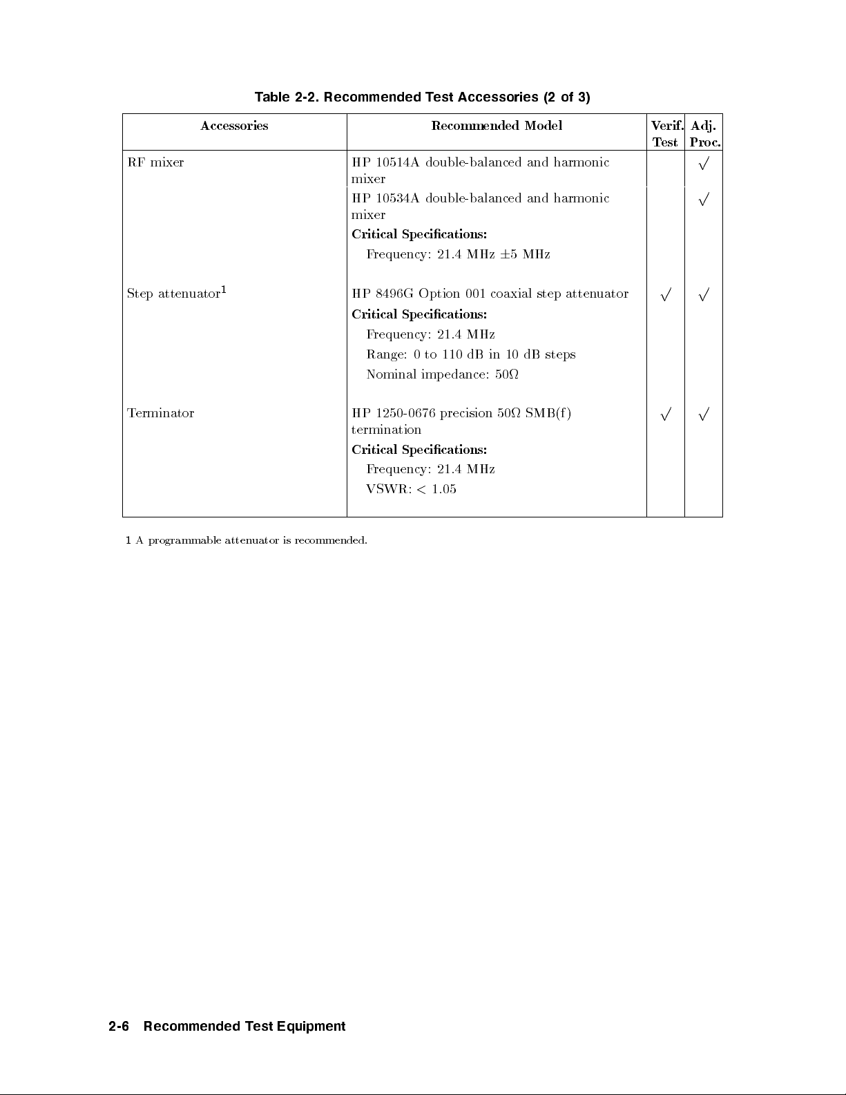
Table 2-2. Recommended Test Accessories (2 of 3)
Accessories Recommended Model Verif.
RF mixer HP 10514A double-balanced and harmonic
mixer
HP 10534A double-balanced and harmonic
mixer
Critical Specications:
Frequency: 21.4 MHz65 MHz
Step attenuator
Terminator HP 1250-0676 precision 50 SMB(f )
1
HP 8496G Option 001 coaxial step attenuator
Critical Specications:
Frequency: 21.4 MHz
Range: 0 to 110 dB in 10 dB steps
Nominal imp edance: 50
termination
Critical Specications:
Frequency: 21.4 MHz
VSWR:<1.05
Test
p p
p p
Adj.
Proc.
p
p
1
A programmable attenuator is recommended.
2-6 Recommended Test Equipment

Table 2-3. Recommended Test Accessories (3 of 3)
Cables and Adapters | Recommended Mo del Verif.
Cables
HP 85680-60093 123 cm (48.4 in) 50 BNC(m) to SMB(f )
HP 10503A 122 cm (48 in) 50 coax BNC(m) to BNC(m)
HP 8120-5016 160 mm (6.3 in) SMB(f ) to SMB(f )
Adapters
HP 1250-1745 50 APC-3.5(f) to N(f )
HP 1251-2277 50 BNC(f) to dual banana plug
HP 1250-1474 precision 50 N(f ) to BNC(f )
HP 1250-1477 precision 50 N(f ) to BNC(m)
HP 1250-1476 precision 50 N(m) to BNC(f )
HP 1250-1473 precision 50 N(m) to BNC(m)
HP 1250-1236 50 SMB(f) to BNC(f )
HP 1250-0672 50 SMB(f) to SMB(f )
HP 1250-0896 50 SMB(m) to BNC(m)
HP 1250-1237 50 SMB(m) to BNC(f )
HP 1250-0674 50 SMB(m) to SMA(f )
HP 1250-0669 50 SMB(m) to SMB(m)
HP 1250-0671 50 SMB(m) to N(m)
HP 1250-1391 50 SMB tee(f ) (m) (m)
Test
p p
p p
p p
p p
p p
p p
p p
p p
p
p p
p
p
p
p
p
p p
p p
Adj.
Proc.
Recommended Test Equipment 2-7

Service Kit
The HP 71000 system service kit is the general service kit for HP 70000 mo dular measurement
system (MMS) mo dules. This kit includes servicing to ols required to repair all MMS modules,
and a mo dication procedure for the HP 70001A mainframe. The mo dication allows access
to MMS mo dules during bench testing and repair.
Table 2-4.
Contents of the HP 71000 system service kit (HP part number 71000-60002)
Quantity Recommended Model
10 HP 2110-0695 1.5A, 125V fuse
10 HP 2110-0700 1.0A, 250V fuse
10 HP 2110-0701 1.6A, 250V fuse
10 HP 2110-0703 6.3A, 250V fuse
10 HP 2110-0710 2.0A, 250V fuse
1 HP 5002-0685 cable puller
1 HP 5021-6773 cable puller
1 HP 5021-7445 pin straightener
7 HP 5061-9021 309 mm (12.2 in) SMB(f ) to SMB(f ) cable
3 HP 85680-60093 123 cm (48.4 in) 50 BNC(m) to SMB(f ) cable
1 HP 70001-00038 modied mainframe cover, right
1 HP 70001-00039 modied mainframe cover, left
1 HP 70001-60013 extender module
1 HP 71000-90015 installation note
2 feet HP 8160-0035 RFI RND STR.0940
10 feet HP 8160-0484 RFI RND BEC.125D
2 feet HP 8160-0495 2.54 x 1.57mm chromeric gasket
1 HP 8710-1651 short 8 mm hex-ball driver
1
1 HP 8710-1728 bandpass lter tuning tool
1 HP 9211-0065 20.5L x 6.5W container
2 HP 9222-0316 bag BR 6.0 x 20.0D
1 HP 9222-0320 bag BR 10.0 x 20.0D
7 HP 9222-1364 bag shield zip 6 x 8
6 HP 9222-1417 bag shield zip 4 x 4
2 HP 9222-1675 bag shield zip AY12
1
An HP 8710-1307 long 8 mm hex-ball driver is also available separately.
2-8 Recommended Test Equipment
 Loading...