


User's Guide
HP
Color
70004A
Display
ABCDE
HP Part No. 70004-90061
Printed in USA January 1998
Edition A.0.0

Notice
The information contained in this document is subject to change without notice.
Hewlett-Packard makes no warranty of any kind with regard to this material, including,
but not limited to, the implied warranties of merchantability and tness for a particular
purpose. Hewlett-Packard shall not be liable for errors contained herein or for incidental or
consequential damages in connection with the furnishing, performance, or use of this material.
Restricted Rights Legend.
Use, duplication, or disclosure by the U.S. Government is subject to restrictions as set forth
in subparagraph (c) (1) (ii) of the Rights in Technical Data and Computer Software clause at
DFARS 252.227-7013 for DOD agencies, and subparagraphs (c) (1) and (c) (2) of the Commercial
Computer Software Restricted Rights clause at FAR 52.227-19 for other agencies.
Trademarks
ITEL
is
a
U
.S.
trademark of Intelligent Interfaces Inc.
c
Copyright Hewlett-Packard Company 1990, 1998
All Rights Reserved. Reproduction, adaptation, or translation without prior written permission
is prohibited, except as allowed under the copyright laws.
1400 Fountaingrove Parkway, Santa Rosa, CA 95403-1799, USA

Certication
Hewlett-P
time
measurements
T
echnology
facilities
of
shipment
of
ackard
,
to
other
Company
from
the
are
traceable
the
extent
International
certies
factory
to
allowed
that
this
product
.
Hewlett-P
the
United
by
the Institute's calibration facility, and to the calibration
ackard further certies that its calibration
States
National
Standards Organization members.
met
its published specications at the
Institute of Standards and
Warranty
This
Hewlett-P
workmanship
ackard
for
a
instrument
period
product is warranted against defects in material and
of one year from date of shipment. During the warranty period,
Hewlett-Packard Company will, at its option, either repair or replace products which prove to
be defective.
For warranty service or repair, this product must be returned to a service facility designated by
Hewlett-Packard. Buyer shall prepay shipping charges to Hewlett-Packard and Hewlett-Packard
shall
pay
shipping
country
.
Hewlett-P
use
with
that
instrument.
shipping
charges
ackard
an
instrument will execute its programming instructions when properly installed on
charges
,
duties
, and taxes for products returned to Hewlett-Packard from another
warrants
Hewlett-P
to
return
the
product
to
Buyer
.
However
, Buyer shall pay all
that its software and rmware designated by Hewlett-Packard for
ackard does not warrant that the operation of the instrument, or
software, or rmware will be uninterrupted or error-free.
Limitation of Warranty
The foregoing warranty shall not apply to defects resulting from improper or inadequate
maintenance by Buyer, Buyer-supplied software or interfacing, unauthorized modication or
misuse, operation outside of the environmental specications for the product, or improper
site
preparation
or
maintenance
.
NO OTHER WARRANTY IS EXPRESSED OR IMPLIED. HEWLETT-PACKARD SPECIFICALLY
DISCLAIMS THE IMPLIED WARRANTIES OF MERCHANTABILITY AND FITNESS FOR A
PARTICULAR PURPOSE.
Ex
clusive Remedies
THE
REMEDIES PROVIDED HEREIN ARE BUYER'S SOLE AND EXCLUSIVE REMEDIES.
HEWLETT-PACKARD SHALL NOT BE LIABLE FOR ANY DIRECT, INDIRECT, SPECIAL,
INCIDENTAL, OR CONSEQUENTIAL D
OR ANY OTHER LEGAL THEORY
AMAGES, WHETHER B
.
ASED ON CONTRA
CT,
TORT,
Assistance
Product maintenance agreements and other customer assistance agreements are available for
Hewlett-Packard products.
For any assistance, contact your nearest Hewlett-Packard Sales and Service Oce.
iii

Safety
The
of
the
CA
UTION
Symbols
following
symbols
WARNING
DANGER
safety
and
The
symbols
its
meaning
CAUTION
are
used
before
throughout
operating
this
manual. Familiarize yourself with each
this instrument.
sign denotes a hazard. It calls attention to a procedure which, if
not correctly performed or adhered to, could result in damage to or destruction
of the product or the user's work. Do not proceed beyond a
CAUTION
sign
until the indicated conditions are fully understood and met.
The
W
ARNING
which,
to
the
if
user
conditions
The
DANGER
sign
not
.
are
Do
denotes
correctly
not
proceed
fully
understood
a
hazard.
performed
beyond
and
It
calls attention to a procedure
or
adhered
a
WARNING
to
, could result in injury
sign until the indicated
met.
sign denotes an imminent hazard to people. It warns the
reader of a procedure which, if not correctly performed or adhered to,
could
sign
result
until
in injury or loss of life. Do not proceed beyond a
the indicated conditions are fully understood and met.
DANGER
iv

General
WARNING
Safety
Considerations
The
instructions
only
.
T
o
avoid
are
qualied
The
opening
voltages
being
The
opened.
power
to
of
.
Disconnect
cord
in
this document are for use by qualied personnel
electrical
do
so
.
shock,
do not perform any servicing unless you
covers or removal of parts is likely to expose dangerous
the instrument from all voltage sources while it is
is connected to internal capacitors that may remain live
for ve seconds after disconnecting the plug from its power supply.
This is a Safety Class 1 Product (provided with a protective earthing
ground incorporated in the power cord). The mains plug shall only be
inserted in a socket outlet provided with a protective earth contact.
Any interruption of the protective conductor inside or outside of the
instrument is likely to make the instrument dangerous. Intentional
interruption is prohibited.
For continued protection against re hazard, replace fuse only with
same type and ratings, (type nA/nV). The use of other fuses or materials
is prohibited.
W
ARNING
Before this instrument is switched on, make sure it has been properly
grounded through the protective conductor of the ac power cable to a
socket outlet provided with protective earth contact.
Any interruption of the protective (grounding) conductor, inside
or outside the instrument, or disconnection of the protective earth
terminal can result in personal injury.
Before this instrument is switched on, make sure its primary power
circuitry has been adapted to the voltage of the ac power source.
Failure to set the ac power input to the correct voltage could cause
damage to the instrument when the ac power cable is plugged in.
v

Operation
at
a
Glance
1
4
INSTR
PRESET
5
Use
the instrument preset key to activate all of the preset
conditions
(The
4
INSTR
of
the presently selected instrument.
N
N
N
N
NNNNNNNNNNNNNNNNNNNNNNNNNNNNNNNNNNNNNNNN
DISPLAY PRESET
5
PRESET
key; when the
softkey is dierent from the
NNNNNNNNNNNNNNNNNNNNNNNNNNNNNNNNNNNNNNNNNNNN
DISPLAY PRESET
softkey is
pressed, it clears the screen and breaks all links that it has
with any modules and then it oers the screen and a keyboard
link to the last module which had the keyboard link.)
2 MSIB The MSIB fault indicator light indicates the status of the MSIB.
If the light is on, there is an MSIB problem.
4
LCL
5
3
Use the local key to reinstate front panel operation if the
instrument has been under remote control.
vi

4
4
PLOT
5
Use the plot key to start a vector (HP-GL) plot output of the
present display screen over HP-IB.
5
4
PRINT
5
Use the print key to start a raster print output of the present
display screen over HP-IB.
6
4
DISPLA
5
Y
Use the display key to access all display functions through
display softkeys.
7
8
9
4
USER
4
MENU
4
INSTR
5
5
5
Use
the
user
key to access user-dened menus or access
downloadable
programs
(DLP
s).
Use the menu key to access all instrument functions and
system
control
operations
.
Use the instrument key to move (allocate) the display and
keypad between instruments in your system.
10
11
4
HOLD
5
4
5
Use
the
further
Use
the
keys
to
entering
hold
key to deactivate an active function to prevent
control
backspace
setting
key
changes
to
move
.
from
a
lower level of menu
the previous level or to backspace the cursor while
text.
12 Custom Keypad The custom instrument keypad, provides up to 15
instrument-specic
instrument
keypad
keys
is
optional
on
a
snap-in
and
may
panel;
not
be
the
part
system.
13
Knob
Use
the
knob
to
change
parameters and select other operating
values; this knob is also referred to as an
RPG [Rotary Pulse Generator] knob.
14
15
455445
Use the two step keys to change parameters up or down.
Numeric Keypad Use the numeric keypad to enter numeric values.
custom
of
your
16
17
4
5
LINE
HP-HIL
Use the line key to switch the display's line power on and o.
Use
the HP-HIL port to connect HP-HIL devices. Some devices
supported
keyboards
by
HP-HIL
,
HP mouse, and track ball.
include the HP 46021A and HP 98203C
18 Memory Card Slot The memory card slot provides additional memory for saving
and recalling instrument states, data, user keys, traces, and
programs.
19 Memory Card
Access Light
The memory card access light indicates that the memory card is
being read or data is being written on it.
20 BAT The memory card battery-low light indicates a low battery
condition on the memory card. The light is o if the memory
card is not inserted.
vii

In
This
Book
This book describes all of the operation procedures and softkeys available under the
4
DISPLAY
key.
Chapter 1 \Hardware Installation", provides information for preparing an HP 70004A
color display for use and using it as part of the structural environment for installing and
conguring instrument modules into HP 70000 Series modular measurement systems.
Chapter 2 \If You Have Problems", provides information to help identify and resolve some
common problems that may occur during or after installation and provides information for
system verication of operation tests.
Chapter 4 \Operating", provides instrument specic front-panel operation instructions.
Chapter 6 \Programming/Remote Operation", provides information on remote programming
and remote operation over HP-IB.
Chapter 7 \Specications and Characteristics", lists the specications and characteristics of
the HP 70004A color display.
Chapter 3 \Front and Rear Panels", describes the menu keys (softkeys and front-panel
keys)
as well as various features available through the front-panel and rear-panel of the
HP
70004A color display.
Chapter 5 \Softkey Reference", describes all of the softkeys available through the
4
DISPLA
key.
Chapter 8 \Error Messages", provides error code information about errors that are reported
on the HP 70004A color display.
5
5
Y
Chapter 9 \Concepts", provides concept information that is related to the use of the
HP 70004A color display.
An
index
is
also
added
at
the
end
of this user's guide to aid the user in nding key items of
interest.
Notation
This
4
KEY
book
5
Conventions
uses
the
following
notation
conventions:
A key name that looks like this represents a key that is physically located on the
instrument and is commonly referred to as a front panel key.
NNNNNNNNNNNNNNNNNNNNNNN
softkey
Text that looks like this (with all lowercase letters) represents a softkey that
accesses another menu of related softkeys.
NNNNNNNNNNNNNNNNNNNNNNN
SOFTKEY
Text that looks like this (with all uppercase letters) represents a softkey that
executes its function.
Display
Text that looks like this represents messages that appear on a display.
Text
Before you begin
on what each control is used for
, you should become familiar with the front panel controls.For information
, refer to \Operation at a Glance" and Chapter 3.
viii

Contents
1. Hardware Installation
Step 1. Unpacking Your HP 70004A Color Display ........ ...... . 1-2
Step 2 (Optional). Installing an Instrument Keypad .............. 1-3
Step 3 (Optional). Installing HP-HIL Devices . . . . . . . . . . . . . . . . . . 1-5
Step 4. Connecting Rear Panel Cables . . . . . . . . . . . . . . . . . . . . . 1-7
Step 5. Setting the MSIB and HP-IB Address . . . . . . . . . . . . . . . . . . 1-8
Step 6 (Optional). Connecting for Remote HP-IB Operation . . . . . . . . . . . 1-9
Step 7 (Optional). Connecting an HP-IB Disk Drive . . . . . . . . . . . . . . . 1-10
Step 8 (Optional). Connecting a printer . . . . . . . . . . . . . . . . . . . . 1-12
Step 9 (Optional). Inserting a RAM Memory Card ............... 1-14
Step
10.
2.
Connecting
Step
11
(Optional).
A
ccessories
If
You Have Problems
If
the
and
System's Power-On Self Test Fails.................... 2-2
the
A
C
Line
P
ower
.
.
...... ...... ...... 1-15
Running the Condence Tests ...... ...... ... 1-17
Options .. ...... ...... ...... ..... .. 1-18
If You Have a Blank or Distorted Display ...... ...... ...... . 2-4
If One of the HP 70004A Color Display Fault Indicators is On . . . . . . . . . . 2-5
If More Than One Module's Error Indicator is Flashing . . . . . . . . . . . . . 2-7
If You Need to Run Display Tests .......... ...... ...... . 2-8
If You Have to Clean the Display's Screen . . . . . . . . . . . . . . . . . . . 2-14
If You Need to Contact Hewlett-Packard...... ..... ...... ... 2-15
Returning
Y
our
Color
Display
to
Hewlett-P
ackard
.
.............. 2-17
3. Introducing the HP 70004A Color Display
Main Features .... ..... ...... ...... ...... ..... 3-2
Front Panel Regions and Hard-Labeled Keys . . . . . . . . . . . . . . . . . . 3-4
Instrument Keypads for a Spectrum Analyzer ................. 3-11
HP-HIL Keyboards . . . . . . . . . . . . . . . . . . . . . . . . . . . . . . 3-13
Rear-Panel Connectors and Address Switches ................. 3-16
4. Operating/Local MSIB Operation
Conguring Display Windows . . . . . . . . . . . . . . . . . . . . . . . . . 4-2
Conguring Display Colors .......................... 4-16
Conguring the Display Clock ........................ 4-20
Printing and Plotting . . . . . . . . . . . . . . . . . . . . . . . . . . . . . 4-22
Selecting and Saving to External Mass Storage Devices . . . . . . . . . . . . . 4-30
Miscellaneous User T
asks . . . . . . . . . . . . . . . . . . . . . . . . . . . 4-38
Contents-1

5
5.
4
DISPLA
4
DISPLAY
4
DISPLAY
4
DISPLAY
4
DISPLA
4
DISPLA
4
DISPLA
4
DISPLAY
6.
Programming/Remote Operation
Programming
Programming
Softkey Reference
Y
NNNNNNNNNNNNN
N
5
Main
NNNNNNNNNNNNNNNNNNNNNNNNNNNN
N
5
Hard Copy
N
N
N
N
N
Mass
5
N
N
N
N
N
Adjust
5
Y
N
N
NNNNNNNNNNNNNNNNNNNNNNNNNNNNNNNNNNNNNNNNNN
Config Display
5
Y
NNNNNNNNNNNNNNNNNNNNNNNNNNNNNNNNNNN
5
Address Map
Y
NNNNNNNNNNNNNN
5
Misc
...... ...... ...... ...... ...... . 5-3
N
N
N
N
NNNNNNNNNNNNNNNNNNNNNNNNNNNNN
Storage
N
NNNNNNNNNNNNNNNNNNNNNNNNNNNNNNNN
Color
...... ...... ...... ...... ...... . 5-29
Commands (Quick Reference) .................. 6-1
Commands (Extention Manual Pages) .... ...... .... 6-13
...... ...... ...... ...... ..... 5-6
.
.
.
.
...... ...... ...... ..... 5-12
.
.......................... 5-15
.......................... 5-21
...... ...... ...... ...... ... 5-26
7. Specications and Characteristics
General Specications ..... ...... ...... ..... ...... 7-2
8. Error Messages
2000|2999
Usage
Errors
.
.
.
........................ 8-2
Display-Disruptive Error Messages ...................... 8-3
6000|6999 Hardware-Warning Errors . . . . . . . . . . . . . . . . . . . . . 8-5
7000|7999 Hardware-Broken Errors ..................... 8-6
9000|9999 Factory Use Errors ........................ 8-7
9.
Concepts
Understanding
Understanding
Understanding
Index
the
RGB
the
HP-IB
Video
Use
of
,
MSIB
Color
,
and
Outputs
.
and
.
the
.
A
Their
.
.
ddress
Use
.
.
.
Map
.
.
...... ..... 9-2
.
.
.
.
.
.
.... ..... 9-4
................ 9-7
Contents-2

Figures
1-1. Available ac Power Cords . . . . . . . . . . . . . . . . . . . . . . . . . . 1-19
2-1. Line Voltage Selector . . . . . . . . . . . . . . . . . . . . . . . . . . . . 2-2
2-2. Line Fuse Removal and Replacement .................... 2-3
NNNNNNNNNNNNNNNNNNNNNNNNNNNNNNNNNNNNNNNN
N
2-3.
display tests
2-4.
Condence
2-5.
Key
T
est
Menu Keys ........................ 2-8
T
est
.............................. 2-9
..... ...... ..... ...... ...... ..... 2-10
2-6. Knob Test Display ...... ...... ...... ...... ..... 2-11
2-7. Display ID . . . . . . . . . . . . . . . . . . . . . . . . . . . . . . . . . 2-13
2-8. Typical Serial Number Label .... ...... ...... ...... .. 2-15
4-1. RAM Memory Card Battery Replacement .... ...... ...... .. 4-35
4-2.
5-1.
5-2.
5-3.
5-4.
5-5.
5-6.
Memory
Main
Hard
Mass
Example
Using
A
djust
Card
Date
Code
Keys
.
Copy
Storage
of
MSIB
Location
.
.
.
.
.
.
.
Keys
..... ...... ..... ...... ...... .. 5-6
Keys......... ...... ...... ...... .. 5-12
an HP 70900B Local Oscillator Source Accessing an HP-IB Disk Drive 5-13
to Connect the Display to a Remote Antenna Site ...... .. 5-13
.
.
.
.
.
.
...... ...... .... 4-36
.
........................ 5-3
Color Keys ........ ...... ...... ..... .... 5-15
5-7. Cong Display Keys ............................ 5-21
5-8. AddressMapKeys ............................. 5-26
5-9. Misc Keys . . . . . . . . . . . . . . . . . . . . . . . . . . . . . . . . . 5-29
Tables
1-1. Optional Accessories for the HP 70004A Color Display ............ 1-18
1-2. ITEL Interface Models ........................... 1-20
2-1. Default MSIB AddressMap... ...... ...... ...... .... 2-3
2-2. HP Service Centers .. ...... ...... ...... ...... .. 2-16
2-3. Packaging for an 8/8 Module (Color Display)................. 2-18
5-1. HP P
5-2. Mapping of Display P
5-3. Default Values of
aintJet Color Map . . . . . . . . . . . . . . . . . . . . . . . . . . .
ens to Plotter Pens................... 5-9
NNNNNNNNNNNNNNNNNNNNNNNNNNNNNNNNNNNNNN
copy options
...................... 5-11
5-4. Default Color Values for the Edit Colors Menu . . . . . . . . . . . . . . . . 5-17
5-5. Default V
5-6. Red, Green, and Blue V
5-7. Red, Green, and Blue V
alues for the Monochrome Display . . . . . . . . . . . . . . . . .
alues for Vision Enhnc 1 . . . . . . . . . . . . . . . 5-19
alues for Vision Enhnc 2 . . . . . . . . . . . . . . . 5-19
5-8. Red, Green, and Blue Values for the Optical Filter . . . . . . . . . . . . . . 5-20
5-7
5-18
Contents-3

Hardware Installation
This chapter contains information needed to prepare an HP 70004A color display for use in
an HP 70000 Series modular measurement system. The information presented is general in
nature; for more detailed information on cabling congurations, module placement, and MSIB
addressing, refer to the
Manual
.
HP 70000 Modular Spectrum Analyzer Installation and Verication
1
Step 1. Unpacking Your HP 70004A Color Display
Step 2 (Optional). Installing an Instrument Keypad
Step 3 (Optional). Installing HP-HIL Devices
Step 4. Connecting Rear Panel Cables
Step 5. Setting the MSIB and HP-IB Address
Step
6
Step
7
Step
8
Step
9
Step
10.
Step
11
A
ccessories
(Optional).
(Optional).
(Optional).
(Optional). Inserting a RAM Memory Card
Connecting the AC Line Power
(Optional). Running the Condence Tests
and Options
Connecting
Connecting
for
an
Remote
HP-IB
Connecting a printer
::::: ::::::: ::::::: :::::: ::::::: ::::::: ::::::: :::::: ::::::: ::::::: :::
::::: ::::::: ::::::: ::::::: :::::: ::::::: ::::::: :::
::::::: :::::: ::::::: ::::::: :::::: ::::::: ::::::: :::::: ::
::::::: ::::::: :::::: ::::::: ::::::: :::::: ::::::: :
HP-IB
Disk
Operation
Drive
:::::::::::::::::::::::::::::::::::::::::::::::::::::
:::::: ::::::: ::::::: :::::: ::::::: ::::::: ::::::: :::::
:::::: ::::::: ::::::: :::::: ::::::: ::::::: :::
:::::: ::::::: :::::: ::::::: ::::::: :::::: :::
:
:
:
:::::: ::::::: :::::: ::::::: ::::
:
:
:
:::::::::::::::::::::::::::::::::::::
:::::: :::::: ::::::: ::::::: ::::::: :::::: :::
:::::: ::::::: ::::::: :::::: ::::::: ::::::: ::
1-2
1-3
1-5
1-7
1-8
1-9
1-10
1-12
1-14
1-15
1-17
1-18
Hardware Installation 1-1

Step
1
1.
Unpacking
Y
our
HP 70004A Color Display
Unpack your color display from its shipping container.
2
Inspect the shipping container and contents thoroughly to ensure that it was not damaged
during shipment.
If
the
container
both
mechanically
nearest
materials
Hewlett-P
for
or
the
cushioning
and
electrically
ackard
carrier's
material
Sales
and
inspection.
.
If
the
Service
is
damaged, check the contents of the shipment
contents are damaged or defective, contact your
Oce. (Refer to Table 2-2 .) Keep the shipping
3
Verify that all parts and materials were included in the shipping container
for HP part number listings
.)
. (Refer to Table 1-1
One: HP 70004A color display
One:
HP 70004A Color Display User's Guide
One Set: MSIB Rear Panel Cables
One: ACPower Cord
(Optional): HP-IB Rear Panel Cables
(Optional): Instrument Keypads
(Optional): HP-HIL devices
(Optional): Memory Cards
1-2 Hardware Installation

Step
2
(Optional).
Installing
an
Instrument
K
eypad
Step
2
(Optional).
Installing
an
Instrument Keypad
To remove an instrument keypad (with release button):
1. Depress the release button, located on the right-hand side of the keypad, and the
instrument keypad should snap out.
To install a custom instrument keypad (with release button):
1. Insert the left side of the keypad (2) into the front panel.
2. Press the right side of the keypad until it snaps into the front panel.
Instrument keypads execute commonly used instrument functions and duplicate operation
of corresponding
4
MENU
5
softkeys.
There are two dierent release mechanisms for the blank panel:
If the blank panel has a release button on the right-hand side, use the procedure listed
above.
If the blank panel has a slot in the right-hand side, use the procedure on the following page
that utilizes a screwdriver.
Hardware Installation 1-3

Step
2
(Optional).
Installing
an
Instrument
K
eypad
To remove an instrument keypad (without release button):
1.
2.
Insert
Gently
a
bladed
pry
screwdriver
the
screw-driver's
into the keypad's slot (1).
handle to the left. The keypad (2) will snap out of the front
panel.
To install a custom instrument keypad (without release button):
1.
2.
Insert
Press
the left side of the keypad (2) into the front panel.
the right side of the keypad until it snaps into the front panel.
Instrument keypads execute commonly used instrument functions and duplicate operation
of corresponding
4
MENU
5
softkeys.
There are two dierent release mechanisms for the blank panel:
If the blank panel has a release button on the right-hand side, use the procedure on the
previous page that utilizes a screwdriver.
If the blank panel has a slot in the right-hand side, use the procedure listed above.
1-4 Hardware Installation

Step
3
(Optional).
Installing
HP-HIL
Devices
Step
To connect a HP-HIL keyboard and a mouse:
1. Inspect the two ends of each HP-HIL cable to locate an end with one black dot and an end
2. Plug the two-dot end of the HP-HIL cable into the display's two-dot connector.
3. Plug the one-dot end of the HP-HIL cable into the one-dot connector on the keyboard.
4. Plug the two-dot end of the HP-HIL cable that came with the HP mouse or track ball into
3
(Optional).
with two black dots.
The end with two black dots is always plugged into the two-dot connector of the device
you are linking from, while the one dot end is always plugged into the one-dot connector
of the device you are linking to.
the keyboard's two-dot connector.
Note
The HP mouse has only a two-dot end on its HP-HIL cable. Therefore it must be the last
device in the link.
Installing
HP-HIL
Devices
Hardware Installation 1-5

Step
3
(Optional).
Installing
HP-HIL
To connect an HP mouse or track ball:
Plug
the
the
keyboard's
track
The
HP-HIL
track
ball
ball.
two-dot
do
end
two-dot
not
need
interface
of
the HP-HIL cable that came with the HP mouse or track ball into
connector
a keyboard, they can be connected directly to the display.
supports
most
Devices
or
the two-dot connector of the display; the HP mouse or
relative locator devices including the HP mouse and
1-6 Hardware Installation

Step
4.
Connecting
Rear
P
anel
Cables
Step
To connect the display to another display or mainframe:
4.
Connecting
Rear
P
anel Cables
1;2
1. Connect an MSIB cable between the HP 70004A color display's MSIB OUT connector (1)
and the HP 70001A mainframe's MSIB IN connector (2).
2. Connect an MSIB cable between the HP 70001A mainframe's MSIB OUT connector (3) and
the HP 70004A color display's MSIB IN connector (4).
The MSIB cables are connected serially, coupling the input of one element to the output of
the next until the loop is completed.
3. The cabling shown in this diagram is for a generic spectrum analyzer system; for more
information about connecting cables between various modules used in an MMS system,
refer to the
HP 70000 Modular Spectrum Analyzer Installation and Verication Manual
.
1
Each MMS system is shipped with a unique set of precongured cables; the lengths of required cables may vary.
2
For information on connecting to an external monitor, refer to \Understanding RGB Video Outputs and Their Use"
in Chapter 9.
Hardware Installation 1-7

Step
5.
Setting
the
MSIB
and HP-IB Address
To set the MSIB and HP-IB address switches:
1. Locate the address switches on the rear panel of the display.
2. Set the ve switches labeled COLUMN to the binary value of the display's MSIB column
address.
Setting the COLUMN address of the display, species both the MSIB address and the HP-IB
address of the display.
MSIB Address HP-IB Address
00000 0
00001 1
00010 2
00011 3
1
00100
T
o establish proper system function and MSIB communication, each element in a system must
4
be assigned a unique MSIB address. The MSIB address is selected with an 8-bit binary DIP
(dual in-line package) switch; this 8-bit binary DIP switch is preset for each module at the
factory and may not have to be changed unless you are using a custom addressing
conguration.
Note
Changing MSIB addresses requires an understanding of MSIB addressing rules. If you use a
custom addressing conguration, refer to the
Installation and V
1
The display section's MSIB COLUMN address is factory-preset to 4 and may be changed, but the display's MSIB ROW
erication Manual
.
HP 70000 Modular Spectrum Analyzer
address is permanently set to 0.
1-8 Hardware Installation

Step
6
(Optional).
Connecting
for
Remote
HP-IB
Operation
Step
To operate the display remotely:
1. Locate the address switches on the rear panel of the HP 70004A color display.
2. Set the HP-IB switch to the ON position.
3. Connect an HP-IB cable between the HP 70004A color display's HP-IB connector (1) and
4. Connect an HP-IB cable between the HP 70001A mainframe's HP-IB connector (2) and
6
(Optional).
the HP 70001A mainframe's HP-IB connector (2).
your system controller's HP-IB connector (3).
Your system controller may be any computer/controller (for example,HP9000
Series 200/300 controller) that supports an HP-IB card.
Connecting
for
Remote HP-IB Operation
Hardware Installation 1-9

Step
To connect an HP-IB disk drive
1. Locate the HP-IB address switches on the rear panel of the external HP-IB disk drive.
2. Set the HP-IB address switches to 0. Refer to the user's manual for your external HP-IB
3. Connect an HP-IB cable between the HP 70004A color display's HP-IB connector (1) and
7
(Optional).
disk drive if you use a dierent HP-IB address.
the external HP-IB disk drive's HP-IB connector (2).
Refer to Table 1-1 for recommended models of external HP-IB disk drives.
Connecting
an
HP-IB Disk Drive
1-10 Hardware Installation

Step
7
(Optional).
Example of accessing an HP-IB disk drive through an HP 70900B local oscillator source.
Connecting
an
HP-IB
Disk
Drive
Example
of
using
MSIB
to
connect
to
a remote antenna site.
Hardware Installation 1-11

Step
To connect a printer
1. Locate the printer address switches on the rear panel of the printer being connected.
2. Set the address switches to 1. Refer to the user's manual for your printer if you use a
3. Connect an HP-IB cable between the HP 70004A color display's HP-IB connector (1) and
4. Connect a Centronics printer cable between the \Centronics" connector (3) on the ITEL
8
(Optional).
dierent printer address.
the \HP-IB" connector (2) on the ITEL interface. (Refer to Table 1-2 for recommended
ITEL interface models.)
interface and the printer (4).
To connect a printer to the HP-IB port on the HP 70004A color display, an HP-IB to
Centronics
Bi-tronics
converter is required. The Centronics connector is used to connect to the
parallel
Connecting
port on the back of many Hewlett-Packard printers. (Refer to Table 1-2.)
a
printer
1-12 Hardware Installation

Step
8
(Optional).
Connecting
a
printer
Hardware Installation 1-13

Step
To insert a RAM memory card:
1. Locate the arrow printed on the card label.
2. Insert the card with the arrow on the card matching the arrow above the card-reader slot.
3. Press the card into the slot. When correctly inserted, approximately 19 mm (0.75 in) of
9
(Optional).
the card is exposed.
Inserting
a
RAM Memory Card
Memory cards provide storage media and access routines and instrument personalities; these
are called down-loadable programs (DLPs).
WARNING
Improper card insertion can cause error messages to occur, but generally does not
damage the card or instrument. Care must be taken, however, not to force the card
into the card reader slot.
1-14 Hardware Installation

Step
10.
Connecting
the
A
C
Line
P
ower
Step
1
10.
Connecting
the
A
CLinePower
Conrm that the line-voltage selector is set to the proper ac line voltage.
Failure to set the ac power input to the correct voltage could cause one of two things to
happen when power is applied:
If the switch is set to 115 V and the instrument is connected to 230 V, the fuse will blow.
If the switch is set to 230 V and the instrument is connected to 115 V, the instrument will
not turn on.
WARNING
Before turning this instrument on, make sure the line-voltage selector is set to the
voltage of the ac power source.
115 V position for 90 to 132 Vac line input voltages at 50, 60, or 400 Hz
230 V position for 198 to 264 Vac line input voltages at 50 or 60 Hz
Also make sure that it is grounded through the protective conductor of the ac power cable to
a socket outlet provided with protective earth contact. Any interruption of the protective
(grounding) conductor inside or outside the instrument, or disconnection of the protective
earth terminal, can result in personal injury.
Hardware Installation 1-15
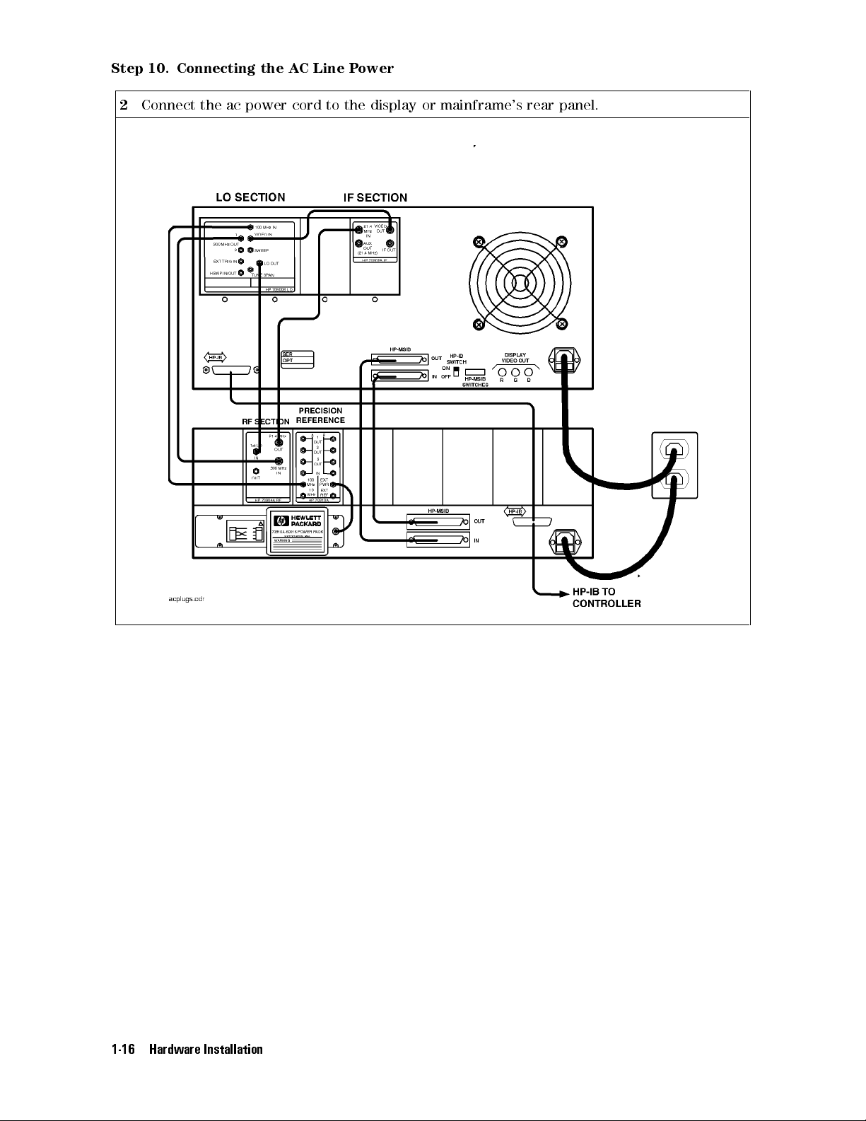
Step
10.
Connecting
2
Connect the ac power cord to the display or mainframe's rear panel.
the
A
C
Line
P
ower
1-16 Hardware Installation

Step
11
(Optional).
Running
the
Condence
T
ests
Step
1
2
11
Press the
Press the
(Optional).
5
4
DISPLA
NNNNNNNNNNNNNN
Misc
key.
Y
NNNNNNNNNNNNNNNNNNNNNNNNNNNNNNNNNNNNNNNNN
,
display tests
Running
,and
the
Condence Tests
NNNNNNNNNNNNNNNNNNNNNNNNNNNNNNNNNNN
CONFID TEST
menu keys to initiate the test.
The Condence Test checks the operation of roughly 90% of the HP 70004A color display.
If the HP 70004A color display fails the Condence Test, it attempts to write anE(error) in
the system state area of the display.
3
Verify that
6001 Confidence test passed
appears in the lower-left corner of the screen.
If the display passes the Condence Test, and the display screen shows no visible
distortion, there is a high level of probability that the display is functioning correctly.
If a fault is found,
6008 Confidence test failed
is displayed. In this event, refer to \If
You Need to Run Display Tests" in Chapter 2 for additional information, or contact your
nearest Hewlett-Packard Sales and Service Oce. (Refer to Table 2-2.)
At power-on, a set of tests that is dierent from the Condence Test is run. The set of
tests run at power-on includes tests for the MSIB capability of the display. The display
indicates whether any of these tests fail, but does not indicate if they pass
.AnMSIB
failure is indicated by a blinkingE(error) indicator in the system state area of the display.
If the Condence Test produces errors and the MSIB is working (no blinkingEindicator),
error messages produced by the Condence Test can be viewed by pressing the
NNNNNNNNNNNNNNNNNNNNNNNNNNNNNNNNNNNNNNNNN
and
REPORT ERRORS
.
4
DISPLAY
5
Hardware Installation 1-17

A
ccessories
The
accessories
part
of
a
precongured
and
that
Options
are
supplied
HP
70000
with
Series
an
HP
modular
70004A color display, ordered separately,oras
measurement system are the same.
When
ordered
with
a
precongured
HP
70000
Series
modular measurement system, cables are
supplied to connect the modules in the particular conguration; for information on dierent
congurations
Spectrum
or
specic
Analyzer
T
able
cable
Installation
1-1.
Optional
lengths and HP part numbers, refer to the
and
Verication Manual
.
HP 70000 Modular
Accessories for the HP 70004A Color Display
Group Description HP Part Number
Options
Instrument
K
eypads
Option 913 Rack mount with handles
Option 908 Rack mount without handles
Option 010 Rack slide
HP
70820A
microwave
1
transition
1
analyzer
1
HP 5062-3979
HP 92576
HP
70820-60086
HP 5062-4073
HP 70874A eye diagram analyzer personality DLP HP 70874-60002
HP 70900A/B local oscillator source HP 70900-60208
HP 70950A optical spectrum analyzer HP 70950-60033
HP-HIL Devices
Keyboard HP 46021A
Keyboard HP
HP-HIL
cable
2
98203C
HP
46020-60001
Track ball HP M1309-60001
HP-IB
Disk
Drives
3.5
"
disk
drive
HP
9122C
Hard disk drive HP 9153C
Memory
Cards
32
KB
RAM
with
battery
HP
85700A
128 KB OTP3ROM with battery HP 85701A
128 KB RAM with battery HP 85702A
256 KB OTP3ROM HP 85703A
256
KB
RAM
HP
85704A
512 KB RAM HP 85705A
KB
3
ROM HP
OTP
85706A
4
HP
to
BNC
A
dapter
(3
required)
1250-1853
ACPower Cables
A
dapters
Hex Ball Driver
Thin-Film Cleaner
MSIB Cables
5
512
Power cable Refer to Figure 1-1.
RCA
8 mm hex ball driver HP 8710-1651
Video Clean Kit HP 92193
HP 70800A 0.5 m MSIB cable
HP 70800B 1.0 m MSIB cable
HP 70800C 2.0 m MSIB cable
HP 70800D 6.0 m MSIB cable
HP 70800E 30.0 m MSIB cable
HP 70207-60003 2.5 m MSIB Y-cable
HP 70207-20003 MSIB cable adapter (2 Quantity)
1
For information on how to rack mount your system, refer to the instructions in
Modular Spectrum Analyzer Installation and Verication Manual
2
This HP-HIL cable is used to connect an HP-HIL keyboard to the HP-HIL connector on the
front panel of the HP 70004A color display.
3
This memory card is One Time Programmable (OTP) Read Only Memory (ROM) .
4
The HP part number of the required ac power plug depends on the country of use.
5
To order MSIB cables, in lengths up to 1.2 km, contact Hewlett-Packard. (Refer to \If You
Need to Contact Hewlett-Packard" in Chapter 2.)
1-18 Hardware Installation
HP 70000
.
 Loading...