


User and Service Guide
Publication number 54701-97003
September 2002
For Safety and Regulatory information, see the pages behind the index.
© Copyright Agilent Technologies 1992-2002
All Rights Reserved
Agilent Technologies 54701A
2.5-GHz Active Probe

Agilent Technologies 54701A 2.5-GHz Active Probe
The Agilent Technologies 54701A 2.5-GHz Active Probe is a probe solution for
high-frequency applications.This probe is designed to be powered from a
connector at the front of the oscilloscope, or with the 1143A Probe Offset
Control and Power Module. It can be used with any measuring instrument
with a 50-Ω input. Following are the main features. See Chapter 3 for full
specifications and characteristics.
• A bandwidth of 2.5 GHz
• Input resistance of 100 kΩ
• Input capacitance of approximately 0.6 pF
• Dynamic range of ±5 V peak ac and ±50 Vdc
• Variable dc offset of ±50 V
• Excellent immunity to ESD and over-voltages
Accessories Supplied
The following accessories are supplied. See “Using probe accessories” in
chapter 1 for a complete list.
• Type N(f) to BNC(m) adapter
• “Walking-stick” ground
• Box of small accessories
• Carrying case
• User and Service Guide
Accessories Available
The following accessories can be ordered.
• Type N(m) to probe tip adapter and 50-Ω termination, 11880A
• BNC(m) to probe tip adapter, 10218A
• Type N(f) to APC 3.5(f) bulkhead adapter, 5081-7722 (For use with the
54120 family. Order with the probe as Option 001.)
2

Options Available
The following options are available.
• Option 001, Type N(f) to APC 3.5(f) bulkhead adapter (To use the probe
with 54120 family)
• Option 0B1, Additional User and Service Guide
Service Strategy
Except for the probe tip, there are no field replacable parts in the Active
Probe. Depending on the warranty status of your probe, if it fails it will be
replaced or exchanged. See chapter 3, “Service,” for further information and
how to return your probe to Agilent Technologies for service.
Option 001
3

In This Book
This book provides use and service documentation for the 54701A 2.5-GHz
Active Probe. It is divided into three chapters.
Chapter 1 shows you how to set up and operate the probe using the power
connector on the oscilloscope or the separately available 1143A Probe Offset
Control and Power Module.
Chapter 2 gives you information about some important aspects of probing and
how to get the best results with your probe.
Chapter 3 provides service information. Included is how to test the probes
performance, how and when to make the one adjustment, and how to
determine if your probe needs repair.
4

Contents
In This Book 4
1 Operating the Probe
To inspect the probe 9
To connect the probe 12
Connecting the probe to the 54120 family oscilloscopes 13
Using the probe with oscilloscope power 14
Using the probe with the 1143A power module 15
Using probe accessories 16
Additional Accessories 20
2 Probing Considerations
Capacitive Loading Effects 25
Ground Inductance Effects 27
Probe Bandwidth 31
Conclusion 32
5

Contents
3Service
Specifications 35
Characteristics 36
General Characteristics 37
Recommended Test Equipment 38
Service Strategy 39
To clean the instrument 40
To return the probe to for service 40
To test input resistance 42
To test dc gain accuracy 43
To test bandwidth 45
To adjust offset zero 49
Failure Symptoms 51
To prepare the probe for exchange 53
Replaceable Parts 54
Theory of Operation 56
6

1
Operating the Probe
7
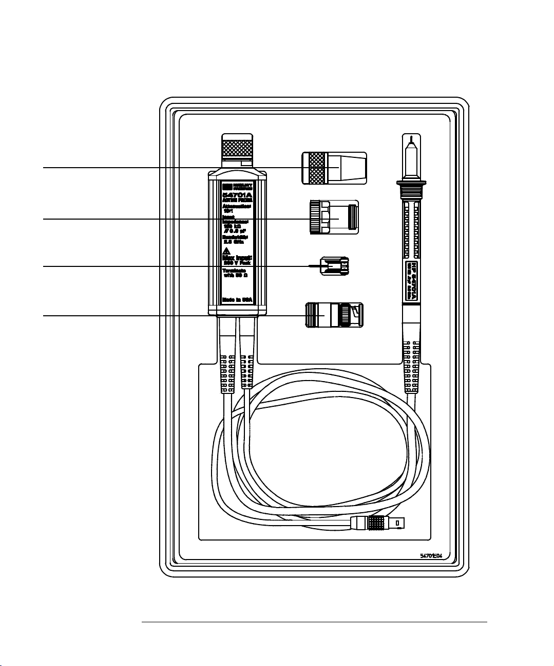
Figure 1
11880A, Type-N(m) to
Probe Adapter
(not supplied, order
separately)
5081-7722A, Type-N(m)
to APC 3.5(f) Adapter
(supplied as Option 001,
or order separately)
Walking-stick Ground
(supplied)
N(f) to BNC(m) Adapter
(supplied)
Chapter 1: Operating the Probe
Included with the probe is a
box of small accessories. See
Page 16 for a complete list of
accessories.
54710A Active Probe
8

Chapter 1: Operating the Probe
Introduction
This chapter shows you how to connect and operate the 54701A Active Probe.
The following information is covered in this chapter:
• Inspection
• Probe operating range
• Connecting the probe
• Operating the probe with oscilloscope power
• Operating the probe with a power module
• Using accessories
To inspect the probe
❏ Inspect the shipping container for damage.
Keep a damaged shipping container or cushioning material until the
contents of the shipment have been checked for completeness and the
instrument has been checked mechanically and electrically.
❏ Check the accessories.
Accessories supplied with the instrument are listed in "Accessories
Supplied" in table 1, page 16 in this manual.
• If the contents are incomplete or damaged notify your Agilent
Technologies sales office.
❏ Inspect the instrument.
• If there is mechanical damage or defect, or if the instrument does not
operate properly or pass calibration tests, notify your Agilent
Technologies sales office.
• If the shipping container is damaged, or the cushioning materials show
signs of stress, notify the carrier as well as your Agilent Technologies
sales office. Keep the shipping materials for the carrier's inspection.
The Agilent office will arrange for repair or replacement at Agilent
Technologies’ option without waiting for claim settlement.
9

Figure 2
Chapter 1: Operating the Probe
Probe Operating Range
Probe Operating Range
Figure 2 shows the maximum input voltage for the active probe as a function
of frequency. This is the maximum input voltage that can be applied without
risking damage to the probe.
Figure 3
Maximum Input Voltage vs Frequency
Figure 3 shows the operating range of the probe. For the most accurate
measurements and safety for the probe, signals should be within the indicated
operating region.
Area of Optimum
Operating
Probe Operating Range
10
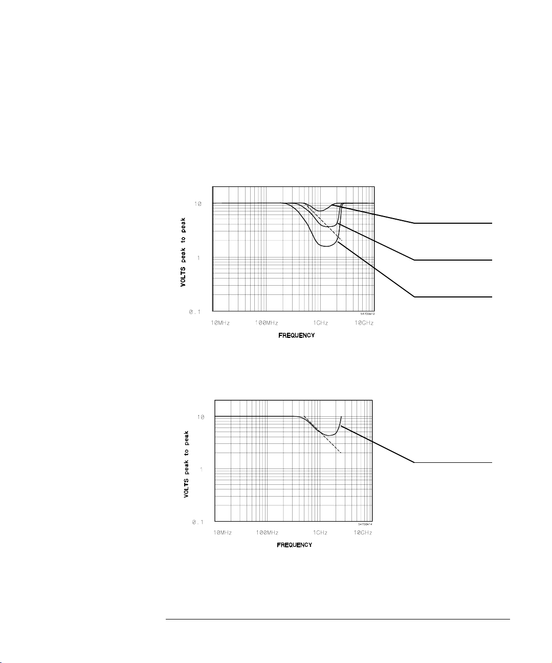
Figure 4
Chapter 1: Operating the Probe
Probe Operating Range
The curves in figures 4 and 5 represent the typical input signal limits for
several levels of second and third harmonic distortion in the output signal. For
input signals below a given curve, the level of harmonic distortion in the
output is equal to or below that represented by the curve. The dashed
straight line in each figure represents the operating range limit as shown in
figure 3 on the previous page.
Second Harmonic
≤ -20 dBc
Second Harmonic
≤ -30 dBc
Second Harmonic
≤ -40 dBc
Figure 5
Second Harmonic Distortion, Input Voltage vs Frequency
Third Harmonic
≤ -40 dBc
Third Harmonic Distortion, Input Voltage vs Frequency
11

Chapter 1: Operating the Probe
Probe Operating Range
To connect the probe
1 Connect the probe output to the instrument input.
The probe output is through a Type-N connector and the probe is designed to
be terminated with 50 Ω 1%.
• If your instrument has a fixed 50-Ω input, connect the probe output.
• If your instrument has selectable input resistance, connect the probe
output and set the instrument input resistance to 50 Ω. If your
oscilloscope has probe power for this probe, it may automatically set the
input resistance to 50 Ω for you.
• If your instrument does not provide a 50-Ω input, connect a Type-N(f) to
BNC(m) adapter and a 50-Ω feedthrough (such as an 10100C) to the
output of the probe. Then, connect the probe to the input of your
instrument.
2 Connect the probe power cable to a Power connector.
Red dots on the cable connector housing align with the connector keys. Align
the keys when inserting the cable connector into the power connector.
CAUTION: The probe power cable connector automatically locks in the mating power
connector. To separate the connectors, you must pull on the knurled part of
the cable connector housing. This releases the lock. If you pull on the cable
the connectors won't release and you may damage the connector or cable.
• If your oscilloscope has the appropriate probe power connector, connect
the probe power cable.
Some oscilloscopes have more than one channel, or signal channels with
separate trigger inputs. In these instruments, a probe power connector
may be associated with a specific input. Be sure to connect the probe
power cable to the correct connector so the instrument will respond
correctly to the presence of the probe.
• If your instrument does not have the appropriate probe power connector,
connect the probe power cable to one of the connectors on the 1143A
Probe Offset Control and Power Module. The 1143A provides probe power
and offset control for two probes.
12

Chapter 1: Operating the Probe
Probe Operating Range
3 Calibrate the oscilloscope and probe combination with the instrument
calibration routines.
Some oscilloscopes allow you to calibrate the probe as part of the input signal
path. Consult the oscilloscope User Guide for further information.
• If calibrating the probe with the 54700 family oscilloscope, you must
calibrate the plug-in with the mainframe before calibrating the probe with
the system. Use the following procedure:
a. Calibrate the oscilloscope using the best accuracy procedure.
b. Calibrate the probe with the oscilloscope using the probe calibration
procedure.
When the probe has been calibrated with the 54700 system, the dc
gain, offset zero, and offset gain will be calibrated. The degree of
accuracy specified at the probe tip is dependent on the 54700 system
specifications.
• If using an 1143A power module for probe power, set the Offset controls to
Local and Zero while performing the calibration. Follow the calibration
procedures for your oscilloscope.
CAUTION: An effort has been made to design this probe to take more than the average
amount of physical and electrical stress. However, with an active probe, the
technologies necessary to achieve high performance do not allow the probe to
be unbreakable. Treat the probe with a moderate amount of care. It can be
damaged if it is dropped from excessive heights onto a hard surface.
Connecting the probe to the 54120 family oscilloscopes
There are a few things to consider when connecting the 54701A Active Probe
to one of the 54120 family of high performance oscilloscopes.
• Use the special Type N(f) to APC 3.5(f) bulkhead adapter to connect the
probe output to the input of the test set. The adapter provides the full
bandwidth and pulse fidelity of the probe as well as full mechanical
support. The use of other adapters can compromise signal fidelity and
may be vulnerable to mechanical damage.
13

Chapter 1: Operating the Probe
Probe Operating Range
The Type-N(f) to APC 3.5(f) adapter can be ordered with the probe as
Option 001 or ordered separately, part number 5081-7722.
• The dynamic range of the system will be 3.2 V (6.4 Vp-p) which, with
probe offset, covers most digital technologies.
Using the probe with oscilloscope power
Probe power and offset control are provided by the oscilloscope. There are
several factors to consider about the oscilloscope and probe combination.
• IThe oscilloscope recognizes the presence and type of probe and adapts
the vertical scale factors to reflect the probe characteristics.
• The offset function is transferred to the probe but this is transparent to the
user. The offset will be limited to a range acceptable to the probe. With
54700 family of oscilloscope plug-ins, the offset range is 50 V. See the
sidebar below.
• Since the 54701A is an active probe, the bandwidth of the oscilloscope and
probe combination is a mathematical combination of their individual
specifications.
Equation 1 System Bandwidth =
where
tr1 is the risetime of the oscilloscope.
tr2 is the risetime of the probe
If you are using a 54700 family oscilloscope, the resultant bandwidth with a
specific mainframe, plug-in, and probe combination is noted on a sticker
on the side panel of the plug-in
The probe has limiting designed to avoid excessive power dissipation. The input
operating range of the probe is 5 V. If the input and offset exceeds +14V relative
to the probe tip, the output of the probe will limit at +1.4 V. As the input plus
offset reaches -14 V, the output will limit at -1.4 V; then, it will fold back to
approximately -0.8V as the input plus offset exceeds -14 V. The output of the
probe will remain at the limit voltage until the input plus offset falls below
approximately -8 Vdc.
14
0.35
------------- ------------- ------------- --
2
tr1()
+
tr2()
2

Chapter 1: Operating the Probe
Probe Operating Range
Using the probe with the 1143A power module
Probe power and offset control is provided by the 1143A Probe Offset Control
and Power Module.
1 Set up the power module by following the instructions in the User and
Service Guide.
2 Connect the probe using “To connect the probe” on page 12" of this
guide.
3 Turn on the power for the power module.
4 Set the appropriate Remote/Local switch.
• To control offset voltage with the power module, set the switch to
Local.
• To control the offset voltage remotely, set the switch to Remote.
5 With Local control, set the appropriate Zero/Variable switch.
• To enable the local offset control, set the switch to Variable.
• To disable the local offset control, set the switch to Zero.
6 Connect the probe to the signal to be measured.
If the oscilloscope has an offset feature, be sure that it is set to zero so
that the probe offset does not have to compensate for the oscilloscope
offset.
7 If necessary, adjust the Coarse and Fine offset controls so the desired
part of the signal is displayed on the oscilloscope. See sidebar below.
The offset range is greater than 50 V relative to the probe tip.
Bandwidth issues are the same as covered on the previous page
The probe has limiting designed to avoid excessive power dissipation. The input
operating range of the probe is 5 V. If the input and offset exceeds +14V relative
to the probe tip, the output of the probe will limit at +1.4 V. As the input plus
offset reaches -14 V the output will limit at -1.4 V; then, it will fold back to
approximately -0.8V as the input plus offset exceeds -14 V. The output of the
probe will remain at the limit voltage until the input plus offset falls below
approximately -8 Vdc.
See Also The User and Service Guide for the 1143A Probe Offset Control and Power
Module about remote probe operation.
15
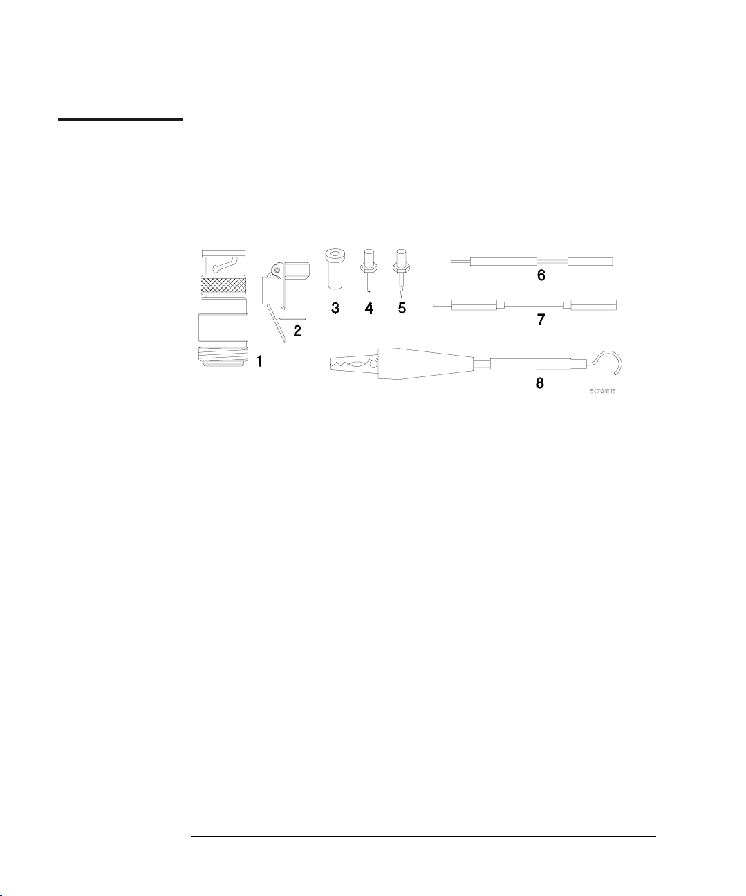
Figure 6
Table 1
Chapter 1: Operating the Probe
Probe Operating Range
Using probe accessories
The following figure and table illustrate the accessories supplied with the
54701A Active Probe.
Accessories Supplied
Item Description Qty Part Number
1 Type-N(f) to BNC(m) adapter 1 1250-0077
2 Walking-stick ground 1 5960-2491
3 Single contact socket 5 1251-5185
4 Standard probe pin 5 54701-26101
5 Sharp probe pin 2 5081-7734
Nut Driver 3/32-in (not shown) 1 8710-1806
6 200-Ω signal lead 1 54701-81301
7 Ground extention lead 1 0650-82103
8 Alligator ground lead 1 01123-61302
* Flexible Probe Adapter 1 54701-63201
* Probe Socket 1 5041-9466
* Coaxial Socket 3 1250-2428
Operating and Service Guide 1 see title page
* These parts are illustrated on pages 18 and 19.
16

Chapter 1: Operating the Probe
Probe Operating Range
Type-N to BNC Adapter
The Type-N(f) to BNC(m) adapter connects the output of the probe to
instruments with a BNC input. If the instrument input does not have a 50-Ω
termination, use an adapter with an integral 50-Ω load or add a 50-Ω
feedthrough (10100C) between the adapter and instrument input.
Walking-stick Ground
The walking-stick ground is the best ground for general probing. It is short,
and the ground wire includes a bead for damping probe resonance. This
provides a well maintained probe response for frequencies to 2.5 GHz.
Single Contact Socket
The single contact sockets can be soldered into a circuit to provide a probe
point to hold the probe tip or ground. The socket accepts 0.018-inch to 0.040inch pins. The sockets accept the probe tips, the walking-stick ground, the
200-Ω signal lead, and the ground extention lead.
Probe Pins
There are two types of replaceable probe pins furnished with the probe. The
0.030-inch round standard probe pin is for general applications. It is made of a
material that will generally bend before breaking. The 0.025-inch round sharp
probe pin has a narrower point and is a harder material. It can be used to
probe constricted areas or penetrate hard coatings.
CAUTION: Do not solder the probe tip into circuitry. Excessive heat may damage the tip
or circuitry inside the probe. If you need to solder something into your
circuitry, use the single contact sockets, ground extention lead, or 200-Ω
signal lead. They are less easily damaged and less expensive to replace.
• To remove and replace probe pins, use the nut driver to unscrew the tip
from the end of the probe.
• Be sure to screw the replacement tip all the way in or the probe may be
intermittent or appear ac coupled.
Nut Driver
The 3/32-in nut driver is provided for easier replacement of the probe tips.
17

Chapter 1: Operating the Probe
Probe Operating Range
200-Ω Signal Lead
This 2-inch orange extention lead includes a molded-in resistor to dampen
resonance caused by the lead inductance. Use this lead and the ground
extention lead to provide a flexible connection to the circuit under test.
There is a tradeoff when using the extention leads. To maintain a clean pulse
response, the probing system bandwidth is limited to 1.5 GHz. Probe
resonance is damped by the walking-stick bead and the resistor in the signal
lead.
Ground Extention Lead
This 2.25-inch black ground lead can be used to extend ground from the
walking-stick to the circuit under test. When used with the walking-stick
ground the probe resonance is damped by the bead on the walking-stick.
Alligator Ground Lead
The alligator ground lead can be used in general applications when the
bandwidth of the signal is 350 MHz or lower. With no signal lead extention the
probe resonant frequency is about 650 MHz.
Flexible Probe Adapter
The flexible probe adapter provides a
high-quality connection between a
coaxial socket and the 54701A probe.
The right-angle connection allows the
probe to remain parallel to a PC board
and the flexibility prevents the leverage
of the probe and cable from damaging PC
board circuitry.
As with any cable-type interconnection,
always apply insertion and removal forces
to the connectors directly, and not
through the cable itself (see the
illustration).
18

Probe Socket
The probe socket is a direct fit to the
shield surface of the 54701A probe.
Use this socket and the single contact
socket to design the highest quality
probing of a PC board. The
illustration shows the socket and the
PC board layout needed to mount the
parts.
Coaxial Socket
The coaxial socket is designed to fit the
standard mini-probe. When used with the
flexible probe adapter, it can be installed in a
circuit so you can probe with the 54701A.
The illustration shows the socket and the PC
board layout needed to mount the socket to
the board.
Chapter 1: Operating the Probe
Probe Operating Range
Probe socket
Single contact
socket
See Also Chapter 2, "Probing Considerations," for a more complete discussion about the
effects of probe connection techniques on signal fidelity.
See Also "Replaceable Parts" chapter 3 for replacement parts that are available but not
listed here.
19
Chapter 1: Operating the Probe
Probe Operating Range
Additional Accessories
The following accessories enhance use of the active probe. For ordering
information, see "Replaceable Parts" in chapter 3.
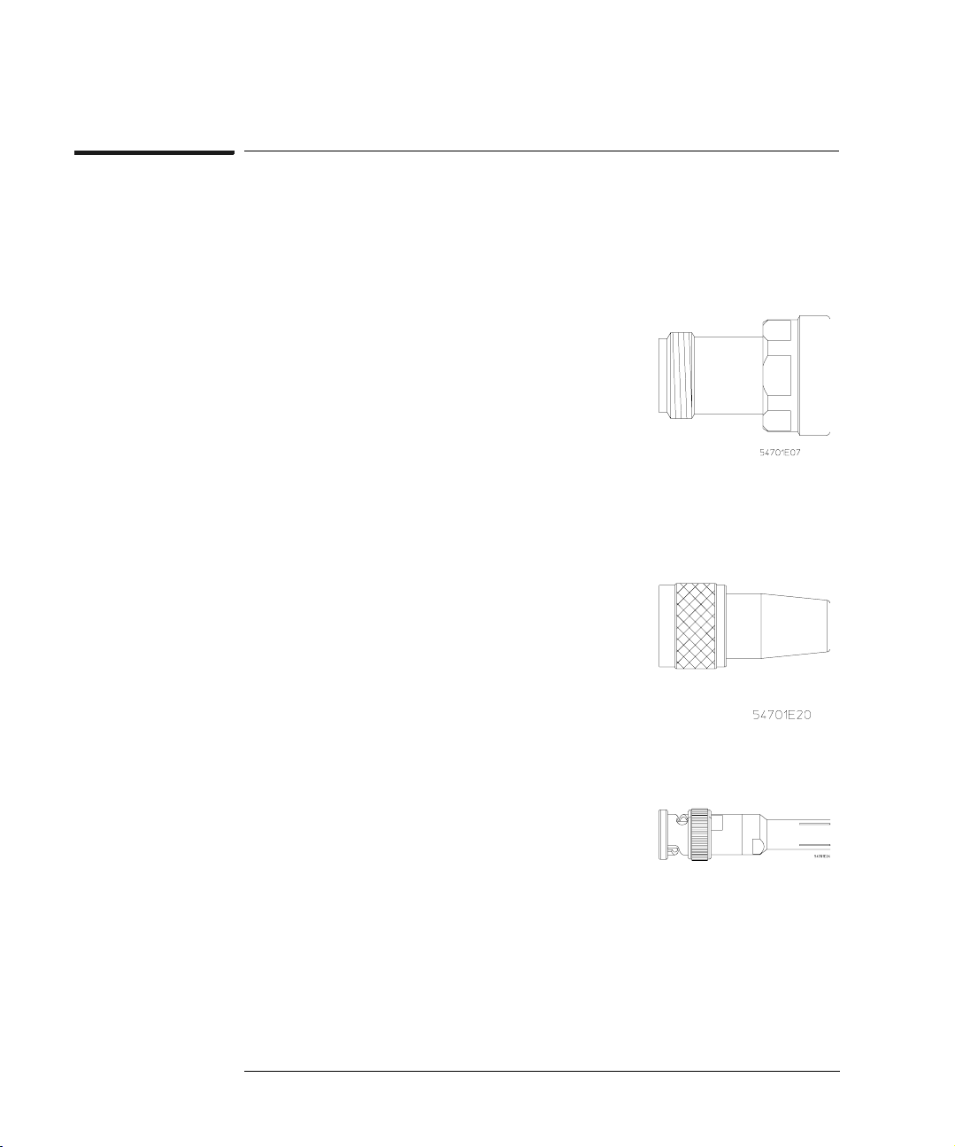
Type-N to APC 3.5 Adapter
The Type-N(f) to APC 3.5(f) bulkhead adapter is an
optional adapter (Option 001, part no. 5081-7722)
specifically designed to connect the active probe to
the input of the 54120 family of high-performance
oscilloscopes. The adapter provides the full
bandwidth and pulse fidelity of the probe as well as
full mechanical support. The use of other adapters
can compromise signal fidelity and may be
vulnerable to mechanical damage. This adapter can
be ordered with the probe as Option 001.
Type-N to Probe Tip Adapter
The 11880A Type-N(m) to probe tip adapter is
available to connect the input of the active probe to
Type-N connectors. It has an internal 50-Ω load. It
can be used for general testing and is specifically
recommended for testing the probe bandwidth.
This adapter must be ordered separately.
BNC to Probe Tip Adapter
The 10218A BNC(m) to probe tip adapter is
available to connect the input of the active probe to
BNC type connectors. It does not have an internal
load so it is not recommended for testing where the
full bandwidth of the probe is needed. This adapter
must be ordered separately.
20
 Loading...