


HP 37717C
Communications
Performance Analyzer
Jitter Concept
Guide
Copyright HewlettPackard Ltd.1997
All rights reserved.
Reproduction, adaption,
or translation without prior
written permission is
prohibited, except as
allowed under the
copyright laws.
Information in this
document may apply to
modules which use the
VxWORKS TM software.
The VxWORKS TM
software was developed by
Wind River Systems, Inc.,
which has copyright to it.
HP Part No. 37717-90258
First edition, July 97
Printed in U.K.
Warranty
The information contained
in this document is subject
to change without notice.
Hewlett-Packard mak es no
warranty of any kind with
regard to this material,
including, but not limited
to, the implied warranties
or merchanability and
fitness for a particular
purpose.
Hewlett-Packard shall not
be liable for errors
contained herein or for
incidental or
consequential damages in
connection with the
furnishing, performance,
or use of this material.
WARNING
Warning Symbols Used
on the Product
!
The product is marked
with this symbol when the
user should refer to the
instruction manual in order
to protect the apparatus
against damage.
The product is marked
with this symbol to
indicate that hazardous
voltages are present
The product is marked
with this symbol to
indicate that a laser is
fitted. The user should
refer to the laser safety
information in the
Calibration Manual.
Hewlett-Packard Limited
Communications Measurements Division
South Queensferry
West Lothian, Scotland EH30 9TG

Jitter Concept Guide
HP 37717C
Communications
Performance Analyzer

About This Book
The information on Jitter testing in this book covers the following subjects::
• An Introduction to Jitter, the Jitter modules and their features.
• Measurement examples.
• Measurement result definitions
• Logging messages
• Self test error codes
For some operations and measurements, information from one of the associated
books listed at the rear of this guide may be required.
iv

Contents
1 Introduction to Jitter Testing
Introduction to Jitter 2
Option A3L [A3M] PDH & STM-1 Electrical Jitter Measurements 3
Option A3V [A3W] PDH & STM-1 Optical & Electrical Jitter Measurements 4
Option A3N [A3P] PDH, STM-1 Electrical & Optical & STM-4 Optical Jitter Measurements 5
Option A3K [A3Q] Jitter & Wander Generator 6
2 Jitter Testing
Multiplexer Jitter Tolerance 8
Wander and Slips 13
Desynchroniser Stress 18
SDH Jitter Tolerance 21
In Service SDH Jitter 24
Tributary Mapping Jitter 26
Selective Jitter Transfer Measurement 29
In Service ATM Jitter 36
3 Result Definitions
Jitter Results 40
v

Contents
4 Jitter Logging Messages
Logging Devices 42
Results Logging 42
5 Jitter Self Test Error Codes
vi

1
“Introduction to Jitter” page 2
“Option A3L [A3M] PDH & STM-1 Electrical Jitter Measurements” page 3
“Option A3V [A3W] PDH & STM-1 Optical & Electrical Jitter Measurements” page 4
“Option A3N [A3P] PDH, STM-1 Electrical & Optical & STM-4 Optical Jitter Measurements” page 5
“Option A3K [A3Q] Jitter & Wander Generator” page 6
1 Introduction to Jitter Testing
.

Introduction to Jitter Testing
Introduction to Jitter
Introduction to Jitter
Errors will occur in a digital signal if jitter at the input of Network Equipment
exceeds a threshold value. It is important to check that the maximum input jitter , that
can be tolerated by that equipment, meets the ITU-T standards for maximum
tolerable input jitter.
Excessive jitter not only causes errors, alarms and loss of synchronization but
directly affects quality of service within the network.
During the transition from a PDH network to mixed PDH/SDH networks, tight
control of jitter levels is essential, especially as new sources of jitter emerge, caused
by the mapping process and network synchronization problems resulting in pointer
movements. The pointer movements cause trib utary jitter at the PDH output ports of
the network element.
Cascading SDH regenerators on long distance links makes a build up of jitter
unavoidable. It is vital to keep the jitter accumulation at the line side of the network
element to a minimum as the SDH line rate is increasingly being used for
synchronization purposes within SDH networks. Excessive line jitter may cause
timing problems between network elements resulting in errors and pointer
movements.
ATM network elements such as switches, routers, multiplexers and cross connects
are also susceptible to jitter and it is therefore important to minimize jitter in ATM
networks.
Wander is an extremely slow variation in the timing of the pulse stream. Excessive
amounts of wander in a network will cause timing problems resulting in pointer
movements. Wander measurements are made at 2 Mb/s, using an external 2 Mb/s
MTS (ITU-T G.811) as a reference. Estimated frame and bit slips are also indicative
of wander effects.
The HP 37717C provides comprehensive Jitter testing at all PDH and SDH rates
from 2 Mb/s to 622.08 Mb/s (STM-4).
PDH Jitter Measurement
Jitter may be measured on the normal PDH Input and results displayed using
RESULTS; JITTER.
SDH Jitter Measurement
Jitter may be measured on the signal at the SDH JITTER INPUT and results
displayed on the RESULTS; SDH JITTER and RESULTS; AUTO TOLER displays.
2
Introduction to Jitter Testing
Option A3L [A3M] PDH & STM-1 Electrical Jitter Measurements
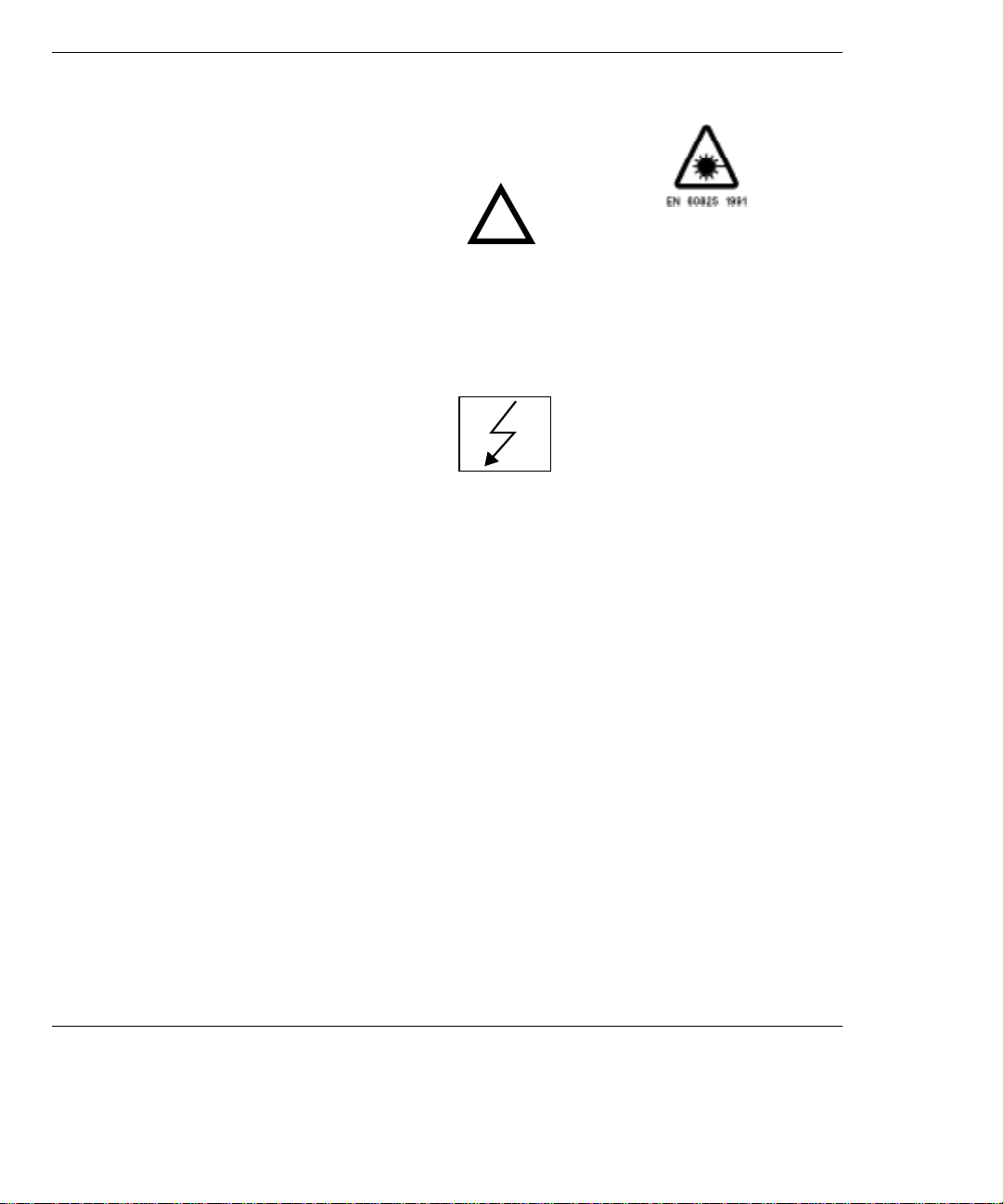
Option A3L [A3M] PDH & STM-1 Electrical
Jitter Measurements
Option A3L provides Jitter measurement at STM-1 Electrical rate and PDH
rates of 2 Mb/s, 8 Mb/s, 34 Mb/s and 140 Mb/s. Compliance to ITU-T O.171
and testing to ITU-T G.825/G.958 is provided.
To measure jitter connect the PDH signal to the PDH IN port of the PDH
module (Options UKK, UKJ and UKN) or the STM-1 Electrical signal to the
STM-1E IN of the A3L module.
Jitter measurements are available at all PDH rates and STM-1 Electrical
rate:
Jitter Hit Count
Jitter Hit Seconds
Jitter Hit Free Seconds
Peak Jitter (Positive and Negative)
Peak to Peak Jitter
Peak rms Jitter
Option A3L [A3M]
Automatic Jitter Transfer with narrowband selective filtering, in
conjunction with Option UHK or A3K, Jitter Generation.
The user can control the number of frequency points at which Jitter is
generated, up to 55.
Fixed input masks, ITU-T G.823 for PDH and ITU-T G.958 for SDH, are
provided. A user defined mask is also available.
Jitter Transfer results are displayed in tabular form and in Graphical form.
The ITU-T pass mask is also displayed on the graph.
Wander measurements are only available at 2.048 Mb/s:
Peak Wander (Positive and Negative)
Peak to Peak Wander
Estimated Bit Slips
Estimated Frame Slips
Implied Frequency Offset
A graphical display of Wander is also provided.
DEMOD OUT connector provides a Demodulated Jitter output.
3
Introduction to Jitter Testing
Option A3V [A3W] PDH & STM-1 Optical & Electrical Jitter
Measurements
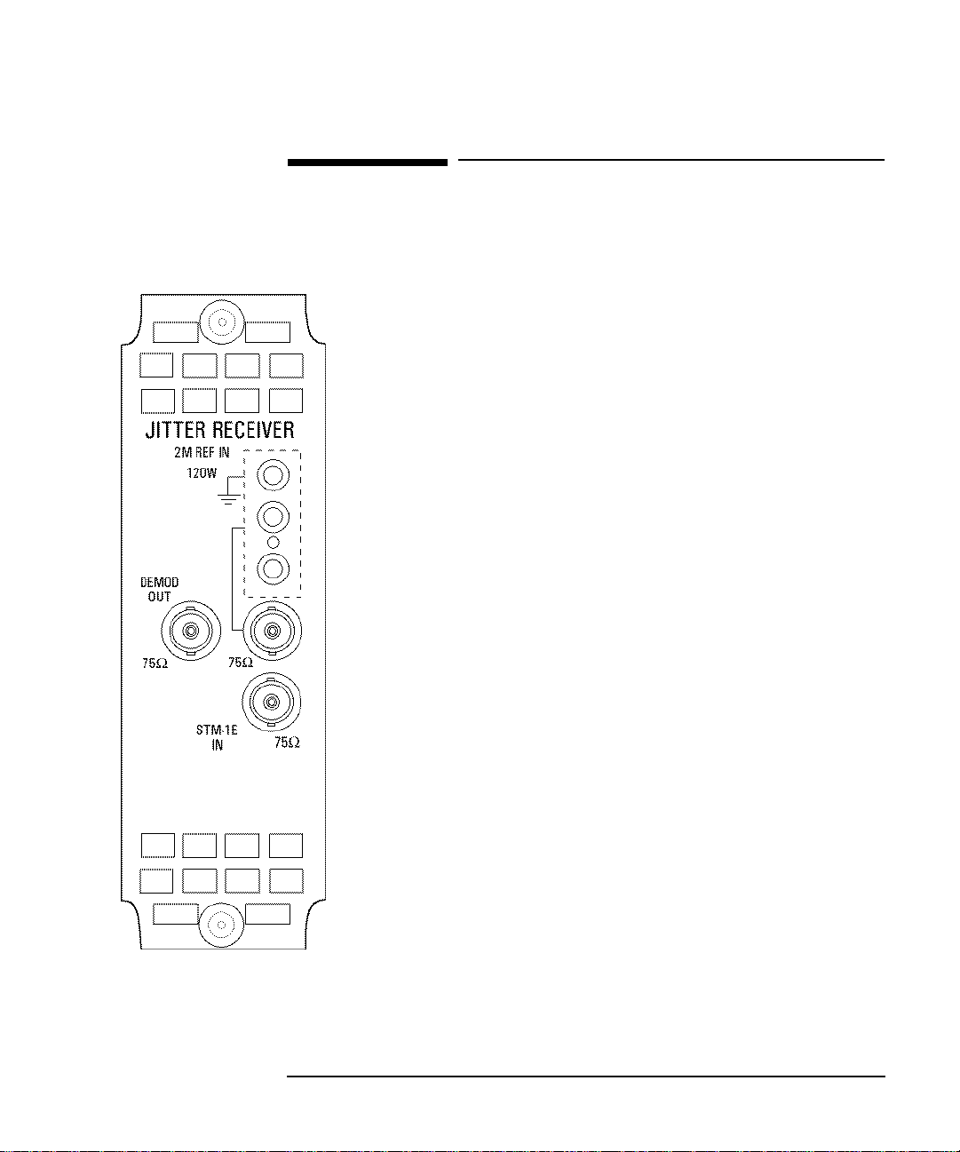
Option A3V [A3W] PDH & STM-1 Optical &
Electrical Jitter Measurements
Option A3V provides Jitter measurement at STM-1 Optical and electrical rate
and PDH rates of 2 Mb/s, 8 Mb/s, 34 Mb/s and 140 Mb/s. Compliance to ITUT O.171 and testing to ITU-T G.825/G.958 is provided.
To measure jitter connect the PDH signal to the PDH IN port of the PDH
module (Options UKK, UKJ and UKN) or the STM-1 Electrical signal to the
STM-1E IN of the A3V module or the STM-1 Optical signal to STM-1/STM4 IN of the A3V module.
Jitter measurements are available at all PDH rates and STM-1:
Jitter Hit Count
Jitter Hit Seconds
Jitter Hit Free Seconds
Peak Jitter (Positive and Negative)
Peak to Peak Jitter
Peak rms Jitter
Option A3V [A3W]
Automatic Jitter Transfer with narrowband selective filtering, in
conjunction with Option A3K or UHK, Jitter Generation.
The user can control the number of frequency points at which Jitter is
generated, up to 55.
Fixed input masks, ITU-T G.823 for PDH and ITU-T G.958 for SDH, are
provided. A user defined mask is also available.
Jitter Transfer results are displayed in tabular form and in Graphical form.
The ITU-T pass mask is also displayed on the graph.
Wander measurements are only available at 2.048 Mb/s:
Peak Wander (Positive and Negative)
Peak to Peak Wander
Estimated Bit Slips
Estimated Frame Slips
Implied Frequency Offset
A graphical display of Wander is also provided.
DEMOD OUT connector provides a Demodulated Jitter output.
4

Introduction to Jitter Testing
Option A3N [A3P] PDH, STM-1 Electrical & Optical & STM-4 Optical
Jitter Measurements
Option A3N [A3P] PDH, STM-1 Electrical &
Optical & STM-4 Optical Jitter Measurements
Option A3N provides Jitter measurement at STM-1 Optical and electrical
rate, STM-4 Optical rate and PDH rates of 2 Mb/s, 8 Mb/s, 34 Mb/s and 140
Mb/s. Compliance to ITU-T O.171 and testing to ITU-T G.825/G.958 is
provided.
To measure jitter connect the PDH signal to the PDH IN port of the PDH
module (Options UKK, UKJ and UKN) or the STM-1 Electrical signal to the
STM-1E IN of the A3N module or the STM-1/STM-4 Optical signal to
STM-1/STM-4 IN of the A3N module.
Jitter measurements are available at all PDH rates, STM-1 Optical and
electrical rate and STM-4 Optical rate:
Jitter Hit Count
Jitter Hit Seconds
Jitter Hit Free Seconds
Peak Jitter (Positive and Negative)
Peak to Peak Jitter
Peak rms Jitter
Option A3N [A3P]
Automatic Jitter Transfer with narrowband selective filtering, in
conjunction with Option A3K or UHK, Jitter Generation.
The user can control the number of frequency points at which Jitter is
generated, up to 55.
Fixed input masks, ITU-T G.823 for PDH and ITU-T G.958 for SDH, are
provided. A user defined mask is also available.
Jitter Transfer results are displayed in tabular form and in Graphical form.
The ITU-T pass mask is also displayed on the graph.
Wander measurements are only available at 2.048 Mb/s:
Peak Wander (Positive and Negative)
Peak to Peak Wander
Estimated Bit Slips
Estimated Frame Slips
Implied Frequency Offset
A graphical display of Wander is also provided.
DEMOD OUT connector provides a Demodulated Jitter output.
5
Introduction to Jitter Testing
Option A3K [A3Q] Jitter & Wander Generator
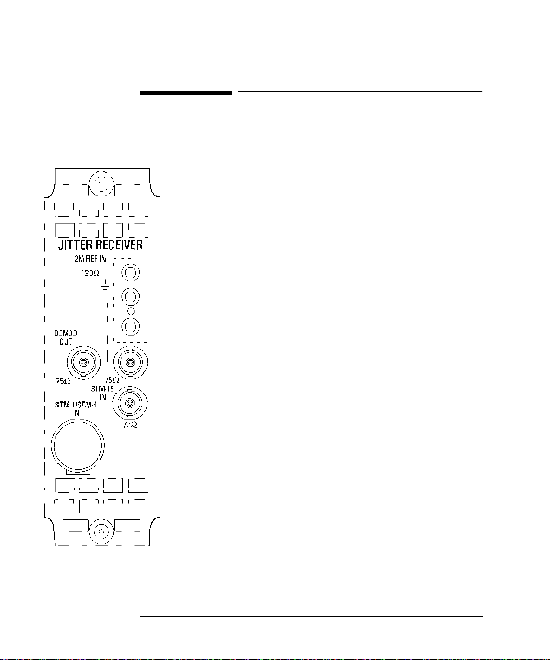
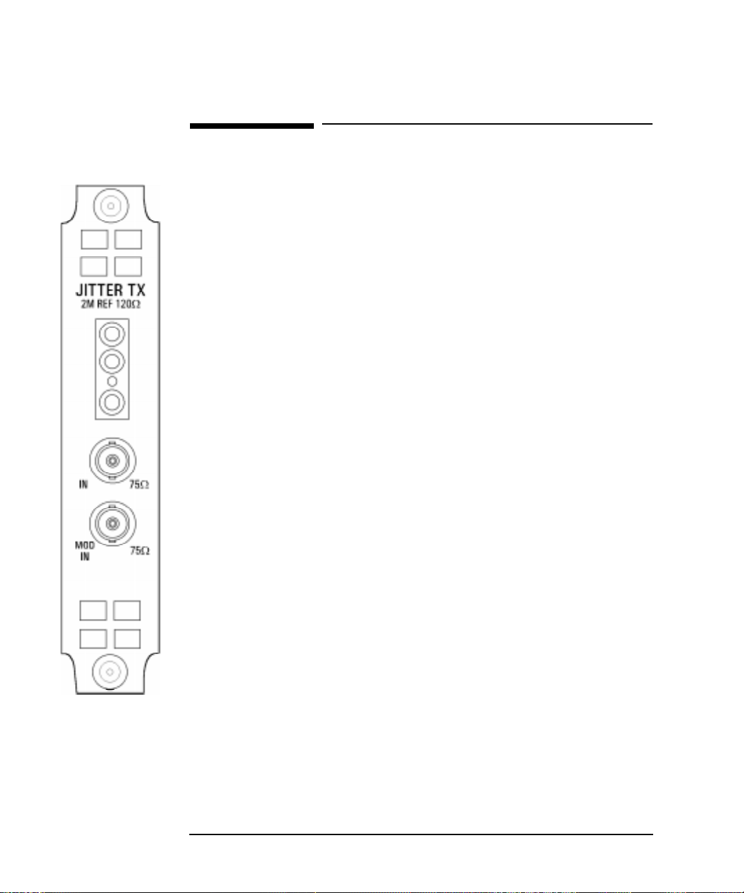
Option A3K [A3Q] Jitter & W ander Generator
Option A3K provides Jitter Generation at all ETSI rates, 2 Mb/s, 8 Mb/s, 34 Mb/s, 140
Mb/s, STM-1 and STM-4 depending on which PDH and SDH options are fitted.
Allows the generation of User Definable Jitter as follows:
Spot frequency Jitter within the ITU-T mask.
Swept frequency Jitter within the ITU-T mask.
Automatic Jitter Tolerance testing of PDH and SDH networks covering high and low
Q systems using fixed jitter tolerance masks. Peak to Peak Jitter and Modulating
frequencies as per ITU-T G.823 (PDH) and ITU-T G.958 (SDH).
The Automatic Jitter Tolerance results are plotted in graphical form relative to the ITUT mask.
The User can control:
the number of frequency points at which Jitter is generated, up to 55.
the Dwell time - time taken at each frequency point.
the Delay time - delay at each frequency point before jitter is generated.
the Bit error threshold - determines the threshold for the Jitter Tolerance
PASS/FAIL decision.
High or Low Q Factor selection (2 Mb/s and 8 Mb/s only)
the type of mask A or B (SDH only)
the Test Pattern
ption A3K
[A3Q]
The jitter modulation can be sourced internally or from an External source. The
external modulation is connected to the MOD IN port.
Allows testing to ITU-T G.825.
Full ITU-T O.171 generation capability from 10 µΗz to 5 MHz
Provides stimulus for Jitter Transfer measurements.
Peak to Peak Jitter and Modulating frequencies as per ITU-T G.823 (PDH) and ITU-T
G.958 (SDH).
Provides Wander Generation at 2 Mb/s, STM-1 and STM-4 depending on which
PDH and SDH options are fitted. An external clock must be connected to the 2M REF
input.
The 2M REF input can be used as an external clock for 2.048 Mb/s PDH transmission.
The wander modulation can be sourced internally or from an external source. The
external modulation is connected to the MOD IN port.
Allows the generation of User Definable Spot frequency Wander within the ITU-T
mask
6

2
“Multiplexer Jitter Tolerance” page 8
“Wander and Slips” page 13
“Desynchroniser Stress” page 18
“SDH Jitter Tolerance” page 21
“In Service SDH Jitter” page 24
“Tributary Mapping Jitter” page 26
“Selective Jitter Transfer Measurement” page 29
“In Service ATM Jitter” page 36
2 Jitter Testing
This Chapter gives examples of the instrument
operation in typical Jitter test applications.
NOTE that actual instrument displays may vary
depending on instrument option.

Jitter Testing
Multiplexer Jitter Tolerance
Multiplexer Jitter Tolerance
Application
It is important that network equipment can operate correctly in the presence of
certain amounts of jitter. ITU-T has specified tolerance masks of jitter amplitude
against jitter frequency which all network equipment must be able to withstand and
provide error free operation.
Jitter is applied at the ITU-T specified jitter frequencies and the amplitude increased
beyond the ITU-T mask limits until errors occur or the maximum possible jitter
amplitude is reached. The resulting amplitude levels are plotted relativ e to the mask
to determine the network elements jitter tolerance.
Default (Known State) Settings
It can be advisable to set the HP 37717C to a known state prior to setting up to make
a measurement. This clears all previous settings and provides a clearly defined
instrument state. The default settings are set by selecting
STORED SETTINGS
STORED SETTING NUMBER 0 and pressing .
OTHER
RECALL
Test Setup Procedure (Jitter Tolerance Test)
The following Option must be fitted to the HP 37717C to perform this test :
• A3K [A3Q] - Jitter Generation A3L[A3M], A3V[A3W] or A3N[A3P] Jitter
Measurement
• UKJ or UKK - PDH Module
This setup procedure is based on 34 Mb/s CMI, PRBS test data with jitter
terminated in 75 Ω. The HP 37717C Automatic jitter tolerance feature is used and
the results plotted on the ITU-T mask.
8
Jitter Testing
Multiplexer Jitter Tolerance
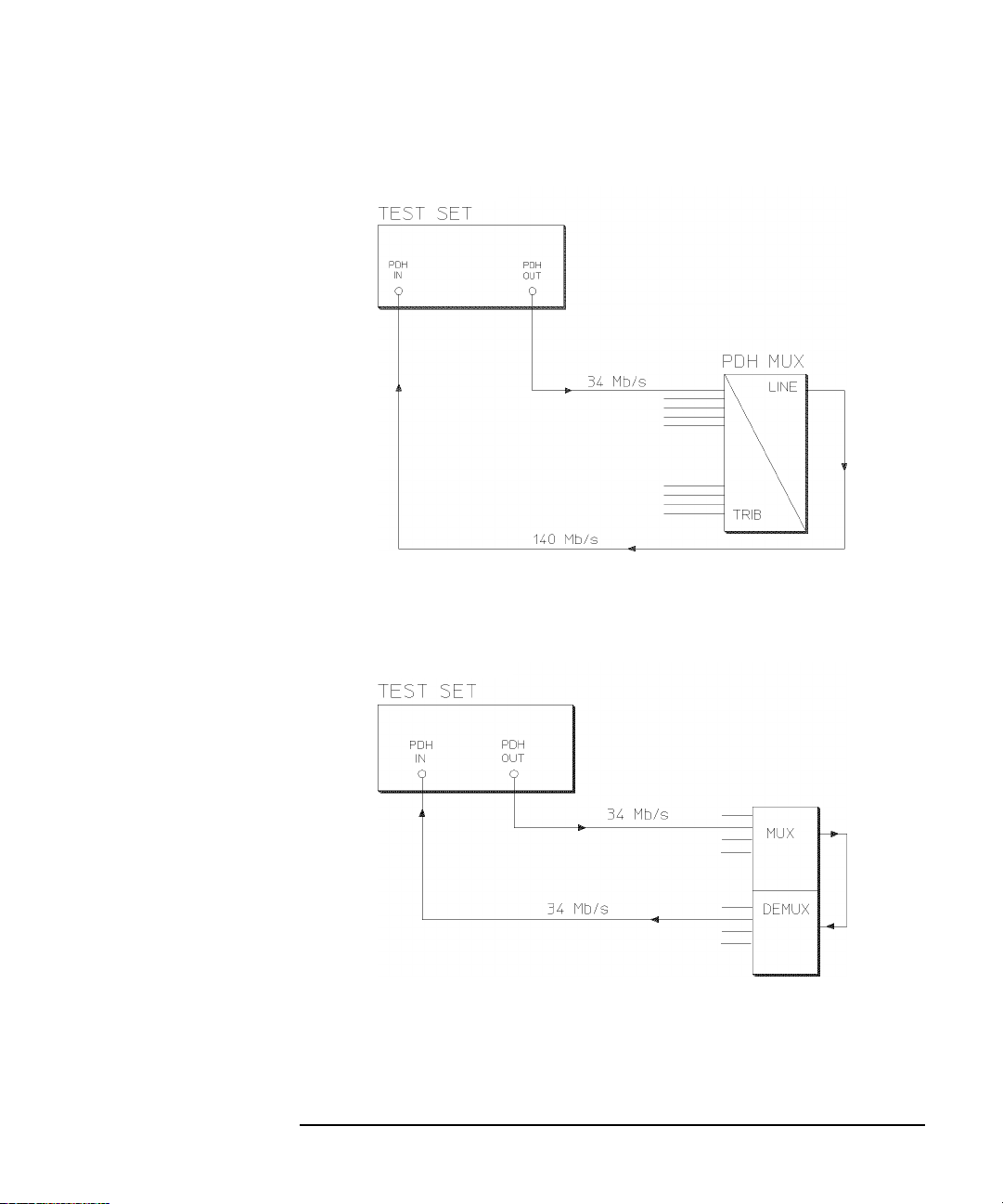
Structured PDH Jitter Tolerance Test
This test can be performed using the Unstructured PDH Option UKK but the
network equipment must be looped back at the higher rate.
Unstructured PDH Jitter Tolerance Test
9
Jitter Testing
Multiplexer Jitter Tolerance
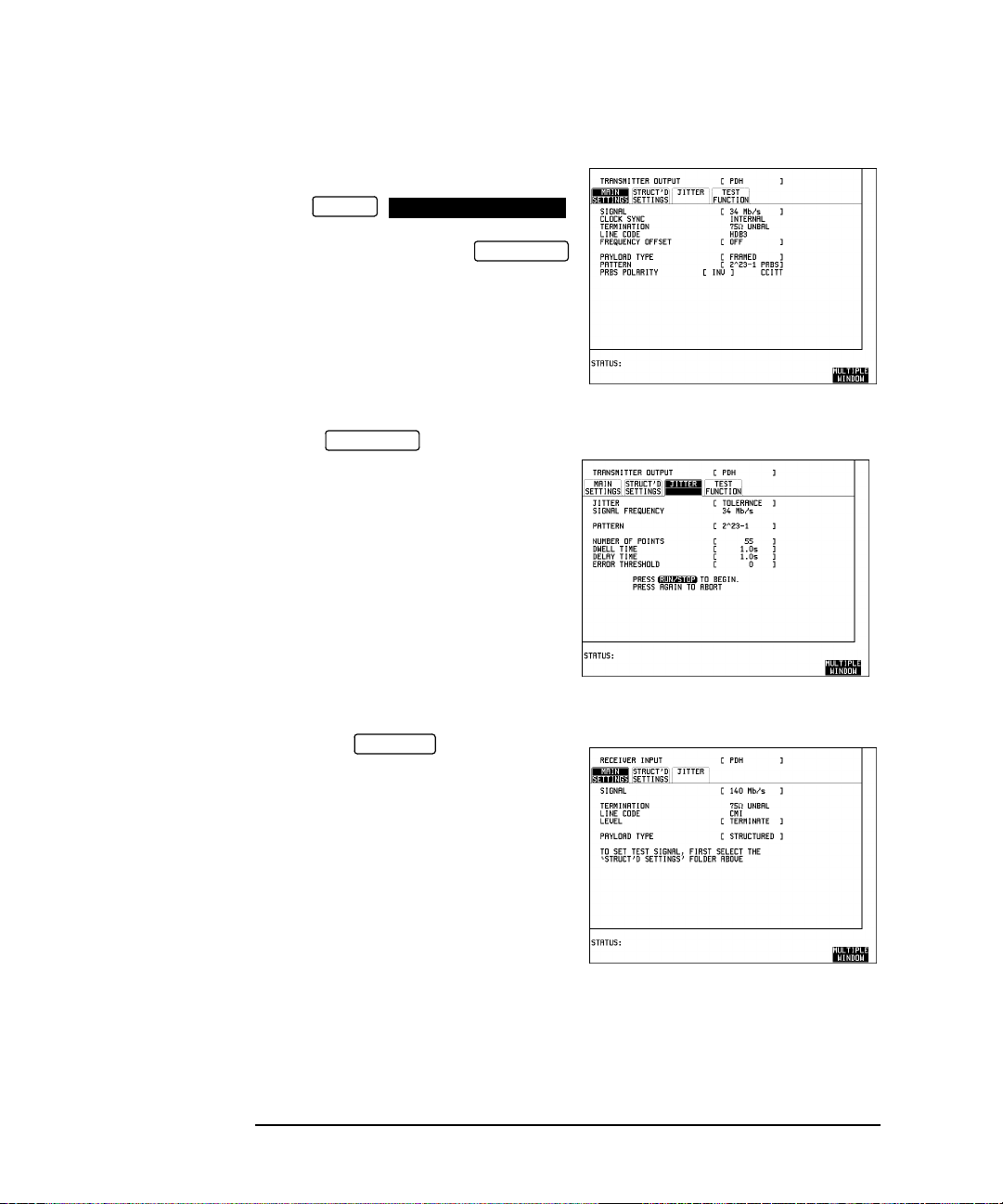
1. Connect the HP 37717C to the network
equipment.
Set the
OTHER
SETTINGS CONTROL
TRANSMITTER AND RECEIVER to
INDEPENDENT and set the
TRANSMIT
display MAIN SETTINGS as shown
opposite.
PAYLOAD TYPE, PATTERN and PRBS
POLARITY selections should match the
reqirement of the network equipment.
2. Select JITTER and set
TRANSMIT
up the display as shown opposite.
The Jitter Tolerance example shown will
take approximately 10 minutes to
complete.
3. Set up the display MAIN
RECEIVE
SETTINGS as shown opposite.
10
Jitter Testing
Multiplexer Jitter Tolerance
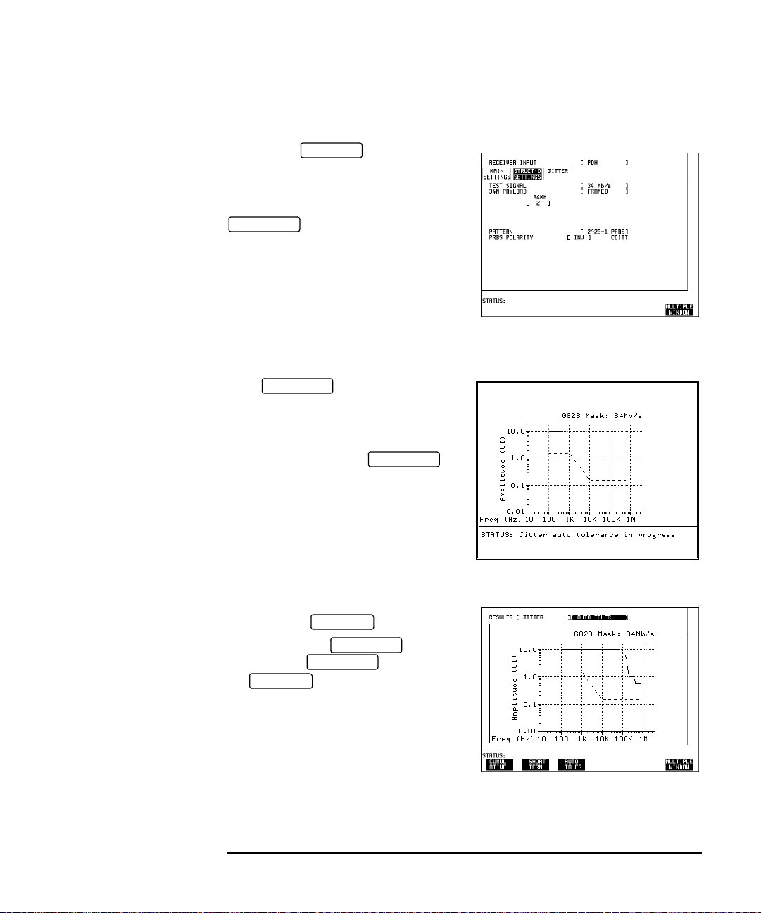
4. Set up the STR UCTURED
RECEIVE
SETTINGS display as shown opposite.
34M PAYLOAD selection should match
the PAYLOAD TYPE selection on the
TRANSMIT
MAIN SETTINGS display.
Run the Test (Jitter Tolerance)
Press to start the
RUN/STOP
measurement.
The measurement takes approximately
ten minutes to complete and its progress
can be monitored on the
TRANSMIT
display.
At the end of the test the results can be
viewed on the display.
The results on the display are
cleared when is pressed but
the display remains available
RESULTS
RESULTS
TRANSMIT
TRANSMIT
until the next Jitter T olerance measurement
is made.
11

Jitter Testing
Multiplexer Jitter Tolerance
If Option A3B or Option A3D Remote Control is fitted the Jitter Tolerance Mask
results can be logged to an External printer .
To Log the Auto Tolerance plot and the results which make up the Jitter Auto
Tolerance plot:
On the display, LOGGING SETUP , select the
OTHER
LOGGING DEVICE
required logging device under LOGGING PORT .
On the CONTROL display, select LOGGING [ON] .
On the display:
for PDH Jitter select RESULTS ; and press
for SDH Jitter, select RESULTS; and press .
OTHER
RESULTS
PRINT NOW
LOGGING
.
JITTER
AUTO TOLER
AUTO TOLER
PRINT NOW
12

Jitter Testing
Wander and Slips
Wander and Slips
Application
The ITU-T specify the frequency limits within which network equipment clocks
should operate. However when network equipment from different manufacturers is
connected together errors in transmission may occur due to timing differences.
To avoid this problem Master Timing sources are typically used as a reference
timing source for all network equipment. The timing reference is distributed
throughout the network as a 2 Mb/s signal.
Problems may arise due to wrongly configured equipment running on internal
clocks or at the junction of different operators network equipment.
Because the timing sources may operate at slightly different frequencies and exhibit
long term frequency drift then phase difference (Wander) may occur, between the
incoming data and the network equipment. This causes "Bit Slips" in the network
equipment buffers and results in frames being repeated or deleted thus reducing the
efficiency of data transfer.
Default (Known State) Settings
It is advisable to set the HP 37717C to a known state before setting up a
measurement. This clears all previous settings and provides a clearly defined
instrument state. The default settings are set by selecting
STORED SETTINGS
Wander and Slips Test Setup Procedure
The following Options must be fitted to the HP 37717C to perform this test :
• A3L or A3V or A3N - Jitter + Wander Measurement and Estimated Slips
• UKJ or UKK - PDH Module
This measurement is made on live traffic and is interfaced at the line terminal
equipment monitor point. The HP 37717C is used in a receive only mode to measure
the Wander and Estimated Bit Slips.
A SINGLE test period of 24 HOURS is used and use of a printer for the recording of
results and alarms is included. A graphical record of the results can be viewed on the
HP 37717C display at the end of the test period.
GRAPH
STORED SETTING NUMBER 0 and pressing .
OTHER
RECALL
13

Jitter Testing
Wander and Slips
Wander and Slips Test
1. Select and set up the display
RECEIVE
as shown opposite.
Selections of TERMINATION, LINE
CODE and PAYLOAD TYPE should
match those of the network equipment.
2. Select the printer and set up the
OTHER
LOGGING
display as shown
opposite.
LOGGING PERIOD and LOG ERROR
SECONDS selections can be modified
according to the users requirements.
14

Jitter Testing
Wander and Slips
3. Set up the
TIMING CONTROL
RESULTS
display as shown
opposite.
The STORAGE selection enables the
graphics. To disable graphics select
STORAGE [OFF].
Graphics can be stored to the instrument
store - INTERNAL or to DISK.
4. Select .
WANDER
BAR GRAPH
RESULTS
is selected but or
WANDER
BIT SLIPS
may be selected without
affecting the measurement.
Run the Test (Wander and Slips)
1. Press until the Monitor
SIGNAL IN
indicator, above the key, is lit.
2. Connect the PDH IN port to the line terminal equipment monitor point.
3. Connect the network master timing source to the HP 37717C 2 Mb/s
REFERENCE input.
If no reference signal is connected to the HP 37717C then the status message "NO
REF" is displayed.
4. Press to start the measurement.
RUN/STOP
15

Jitter Testing
Wander and Slips
If is selected the current
BAR GRAPH
wander measurements are displayed in
graphical form. Three positive and
negative sliding bar graphs, of ± 1 UI,
± 16 UI and ± 256 UI, are displayed.
The Bar Graph displays are additive - in
this example -1.125 UI.
• The measurement results and alarms are available on the display
RESULTS
during the test period.
• The test can be halted at any time by pressing .
RUN/STOP
At the End of the Test (Wander and Slips)
• The Date and Time the test started and the instrument setup are logged on the
printer.
• Any alarms which occur during the test period will be logged on the printer.
• At the end of the test period a complete set of results are logged on the printer.
• A graphical record of the results during the test period can be viewed on the
GRAPH
display. If Remote Control option 1A8 (HP-IB) or 1CW (RS-232-C),
or A3B or A3D is fitted the graph results can be logged to an external printer, at
a later date. See Graphics and External HP 550C DeskJet Printer in the
Masinframe Operating Manual.
• Results and Alarm summaries can be viewed on the display.
GRAPH
The total graphics store capacity is normally 20,000 events. An event is the
occurrence of an error or an alarmThe resolution, determined by the selection made
under STORAGE on the display, affects the ZOOM capability when
RESULTS
viewing the bar graphs. If 1 SECOND is selected all resolutions are available under
ZOOM.
If 1 MIN is selected only 1 MIN/BAR, 15 MINS/BAR and 60 MINS/BAR are
available.If 15 MINS is selected only 15 MINS/BAR and 60 MINS/BAR are
available. If 1 HOUR is selected only 60 MINS/BAR is available.
Up to 10 sets of graphical results can be stored. If an attempt is made to store more
than 10 sets of results, then a first in first out policy is operated and the oldest set of
16

Jitter Testing
Wander and Slips
results will be lost. If graphics are enabled and a test is run which exceeds the
remaining storage capacity, then some previously stored graphical results will be
lost.
T o prev ent accidental overwriting of pre viously stored results the graphics capability
should be disabled, when graphical results are not required, by selecting STORAGE
[OFF] on the display.
RESULTS
17

Jitter Testing
Desynchroniser Stress
Desynchroniser Stress
Application
At the boundary of the SDH network the 2 Mb/s or 140 Mb/s payload is demapped
from the SDH signal. Pointer adjustments in the SDH signal may cause high levels
of tributary jitter in the output payload. Excessive amounts of tributary jitter will
result in errors.
The desynchronizing phase lock loop of the network element should minimize the
level of tributary jitter in the payload but correct operation under stress conditions
must be verified.
The desynchronizing phase lock loop can be stressed by adding pointer movement
sequences (defined in ITU-T standard G.783) to the SDH signal such that the test
VC-4 or TU moves with respect to the SDH frame.
A jitter measurement is made to verify that the desynchroniser output jitter is within
the required specification.
Default (Known State) Settings
It is advisable to set the HP 37717C to a known state before setting up a
measurement. This clears all previous settings and provides a clearly defined
instrument state. The default settings are set by selecting
STORED SETTINGS
Desynchroniser Stress Test Setup Procedure
The following options must be fitted to the HP 37717C to perform this test:
• UKK or UKJ - PDH module
• A3L or A3V or A3N - Jitter measurement module
• A3R - SDH module
• UH1 STM-1 or 130 or 131 - STM-0/1/4 Optical interface
The HP 37717C PDH/SDH test set transmits an STM-4 optical signal carrying 2
Mb/s payload. Pointer movement sequences are added in a controlled manner.
The desynchroniser output is returned to the HP 37717C and a jitter measurement is
performed on the demapped 2 Mb/s signal.
18
STORED SETTING NUMBER 0 and pressing .
OTHER
RECALL
 Loading...