


HP
OmniBER 717
Communications Performance Analyzer
New dual
SONET/SDH
and DS1/DS3
capability
Product specifications
and characteristics
specification
SONET (STS-1, STS-3, OC-1, OC-3, OC-12)
SDH (STM-0, STM-1, STM-4, STM-4c)
PDH (704 kb/s, 2/8/34/140 Mb/s)
DSn (DS1, DS3)
ATM (1.5/2/34/45/140 Mb/s, STM-1, OC-3)
Jitter (2/8/34/140/155/622 Mb/s)
Binary (700 kb/s to 170 Mb/s)

About this documentAbout this document
About this document
About this documentAbout this document
This technical specification provides
contents
detailed product specifications and
characteristics appropriate to and covering
the HP OmniBER 717 and its options.
Options quick reference
Contents
Introduction ............................................................................................... 3
Features ...................................................................................................... 5
Capability summary ............................................................................... 12
Specifications ......................................................................................... 14
PDH and DS1/DS3 options .................................................................... 14
PDH ................................................................................................... 14
DS1/DS3/E1/E3 structured test and interfacing............................ 18
UKK ........................ Page 14
UKJ ................................... 14
UKN.............................14, 53
110 ....................................18
A3R ................................... 22
UH1 .............................29, 67
130 ....................................30
131 ....................................30
120 ....................................34
A3K ................................... 40
140 ....................................40
UHN .................................. 45
A3L .................................... 45
A3V ................................... 45
A3N ................................... 45
UKZ ................................... 56
0YK ................................... 60
USL ................................... 60
A1T ................................... 63
USN................................... 68
UKT ................................... 68
0YH ................................... 72
UH3 ...................................73
UHC ................................... 76
SDH test and interfacing options ........................................................ 22
STM-0/STM-1e test and interfacing .............................................. 22
STM-1 optical interfacing ............................................................... 29
STM-4c, STM-4, STM-1 and STM-0 test
and optical interfacing .................................................................... 30
Dual standard SONET/SDH test and
interfacing options................................................................................. 34
Dual standard SONET/SDH test and interfacing ........................... 34
Jitter generation and measurement options .................................... 40
Jitter generation .............................................................................. 40
Jitter measurement ......................................................................... 45
ATM test and interfacing ...................................................................... 53
ATM cell test options (ETSI only) .................................................... 53
ATM cell test options (ITU-T/ANSI) ................................................ 56
ATM services test options............................................................... 61
STM-1e ATM test and interfacing .................................................. 63
STM-1 optical interfacing ............................................................... 67
STM-4 and STM-1 test and optical interfacing ............................. 68
Binary interfacing and multiple output options .............................. 72
STM-4, STM-1 and STM-0 binary interfaces ................................. 72
PDH binary interfaces ...................................................................... 73
Multiple PDH outputs ...................................................................... 76
General specifications.......................................................................... 77
Disk drive .......................................................................................... 77
Graphics/logging ............................................................................. 77
Printers ............................................................................................. 78
Remote control/printer interface options ...................................... 78
Distributed/remote testing ............................................................. 78
General ............................................................................................. 79
Accessories ...................................................................................... 79
Distributed network analyzer (DNA) .................................................. 80
2
Introduction
introduction
The HP OmniBER 717 is a
modular, portable analyzer
that supports optical and
electrical interfaces for TCarrier, PDH, SONET, SDH,
ATM, jitter and LAN
applications from 704 kb/s to
622 Mb/s (OC-12/STM-4).
The HP OmniBER 717 has an
easy-to-read color display. It
offers an extensive range of
T-carrier, PDH, SONET, SDH,
ATM, jitter and LAN
measurements.
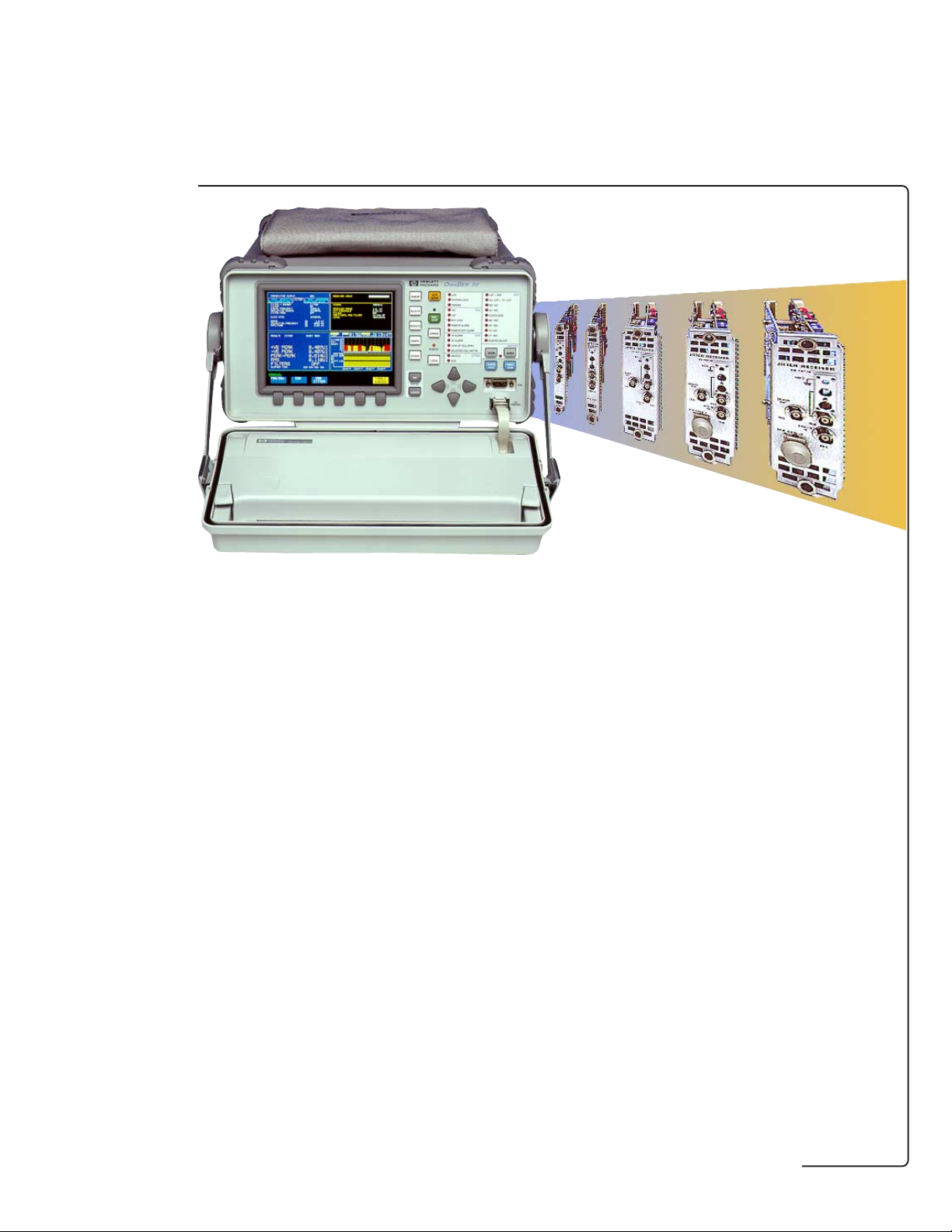
Each analyzer provides
dedicated slots for an optical
interface and the printer/
remote-control module, plus
up to eight slots for other
interface and measurement
modules. This provides the
analyzer with the flexibility to
offer dedicated modules for
T-Carrier, PDH, SONET/SDH,
SDH only, ATM, and jitter
which can be combined
together in the one mainframe
enabling a range of test
requirements to be covered.
The test and interface modules
offer a range of measurements
including detailed overhead,
parity and alarm testing as well
as frequency offset tolerance
tests, frequency measurement
and optical power
measurement. The analyzers
also offer enhanced test
features like pointer sequence
generation, overhead access
and manipulation, overhead
sequence generation and
capture, service disruption
measurement, plus thru mode
capability. The structured
T-carrier and PDH modules
also offer ITU-T M.2100/
M.2101/M.2110/M.2120 testing
with comprehensive ITU-T
G.821 and G.826 in-service and
out-of-service analysis.
Dedicated test hardware
provides all results and
analysis simultaneously, so all
relevant measurements are
made in one test run saving
time and hence money.
For transmit and receive
testing of short-, intermediateand long-reach optical circuits,
there is a choice of 1310 and/
or 1550 nm OC-1/STM-0, OC-3/
STM-1 and OC-12/STM-4
optical modules. Electrical
interfaces at STS-1/STM-0 and
STS-3/STM-1 are also
available, as are jitter
generation and measurement
interfacing options.
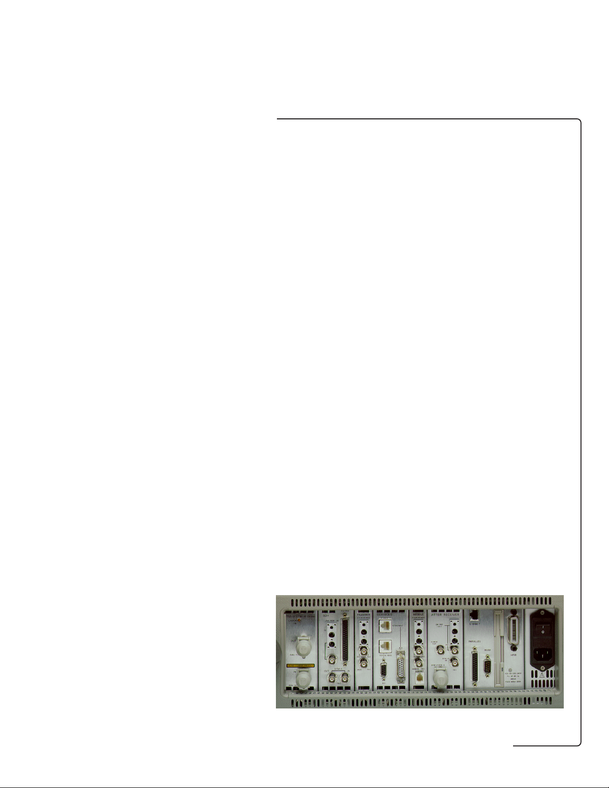
Side view of the HP OmniBER 717
communications performance analyzer
3
features
introduction
HP OmniBER 717 analyzer with
color display and optional in-lid
graphics printer
Test/interface/periheral modules supported include:
● STS-1, STS-3/STS-3c, OC-1, OC-3/OC-3c, OC-12/OC-12c
measurements
● OC-1, OC-3/OC-3c, OC-12/OC-12c optical (1310/1550 nm) and
NRZ interfaces
● STM-0, STM-1, STM-4/STM-4c measurements
● STM-0, STM-1, STM-4/STM-4c optical (1310/1550 nm) and
NRZ interfaces
● Structured PDH interfaces at 2/8/34/140 Mb/s
● Structured T-carrier/ETSI interfaces at DS1/DS3/E1/E3
● ATM services layer testing with/without native LAN
connectivity
● ATM cell layer generation and measurement for ANSI/ETSI
standards(DS1/DS3/E1/E3/OC-3c/STM-1)
● External printer/remote-control interfaces
● In-lid 80 column graphics printer (including screen dump
facility).
4

Features
The HP OmniBER 717 offers
features
powerful, dedicated features
that simplify the assessment of
networks.
This section covers features as
follows:
● General
● Optional PDH
● Optional DS1/DS3
● Optional SDH
● Optional SONET
● Optional ATM cell layer
● Optional ATM services
● Optional jitter
General
Status indicators
HP OmniBER 717:
Stored measurement
graphics
View results graphically.
Event-based time and date
stamped measurement results
are stored by the instrument
with a 1 second resolution. A
text summary of the results is
also available. Graphics
displays may be logged to a
printer.
Parametric testing
Optical power measurement
(requires optical interface
options 130/131 or USN/UKT)
Screen dump
Full-width printing of
instrument screen to
HP OmniBER 717 analyzer's
graphics printer at press of a
key.
‘Trouble Scan’ mode
Use ‘Trouble Scan’ mode to
scan for alarms and to display
non-zero error counts in extra
large characters.
Avoid the need to carry
additional optical power
meters!
5
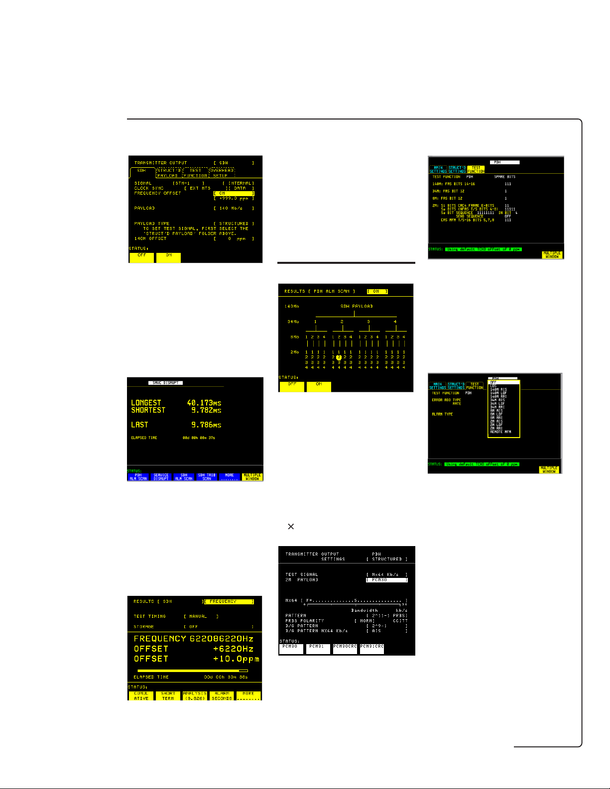
Frequency offset
features
Measure the clock frequency
and the amount of offset from
the Bellcore/ITU-T standard
rate. Out-of-service or inservice frequency measurement can be made at all the
interface rates.
PDH/DSn features
Spare bits access
Test the capability of network
equipment to reliably recover
the clock by varying the clock
rate of the generated data and
checking for the occurrence of
transmission errors.
Protection switch times
Test protection switching
mechanisms to ITU-T G.783,
G.841 or Bellcore GR-253
limits using the service
disruption test.
‘Alarm Scan’ mode
Automatically scan the PDH/
DSn network hierarchy carried
within an SDH/SONET signal
structure for alarms with the
press of a key. ‘Alarm Scan’
mode shows the alarm state of
all alarms in a structured
signal.
N ´ 64 kb/s
Modify the spare bits at 2,
8, 34 and 140 Mb/s interface
rates. Modify and access the
ABCD signaling bits. (CAS
multiframe mode).
Alarm generation
Check your PDH/DSn network
elements and tributary insert
ports using the PDH/DSn alarm
generation facility.
Frequency measurement
Readily check 64 kb/s or
N × 64 kb/s digital paths (to
ITU-T G.704: 1 to 31
contiguous and non-contiguous
timeslots).
6
SDH features
features
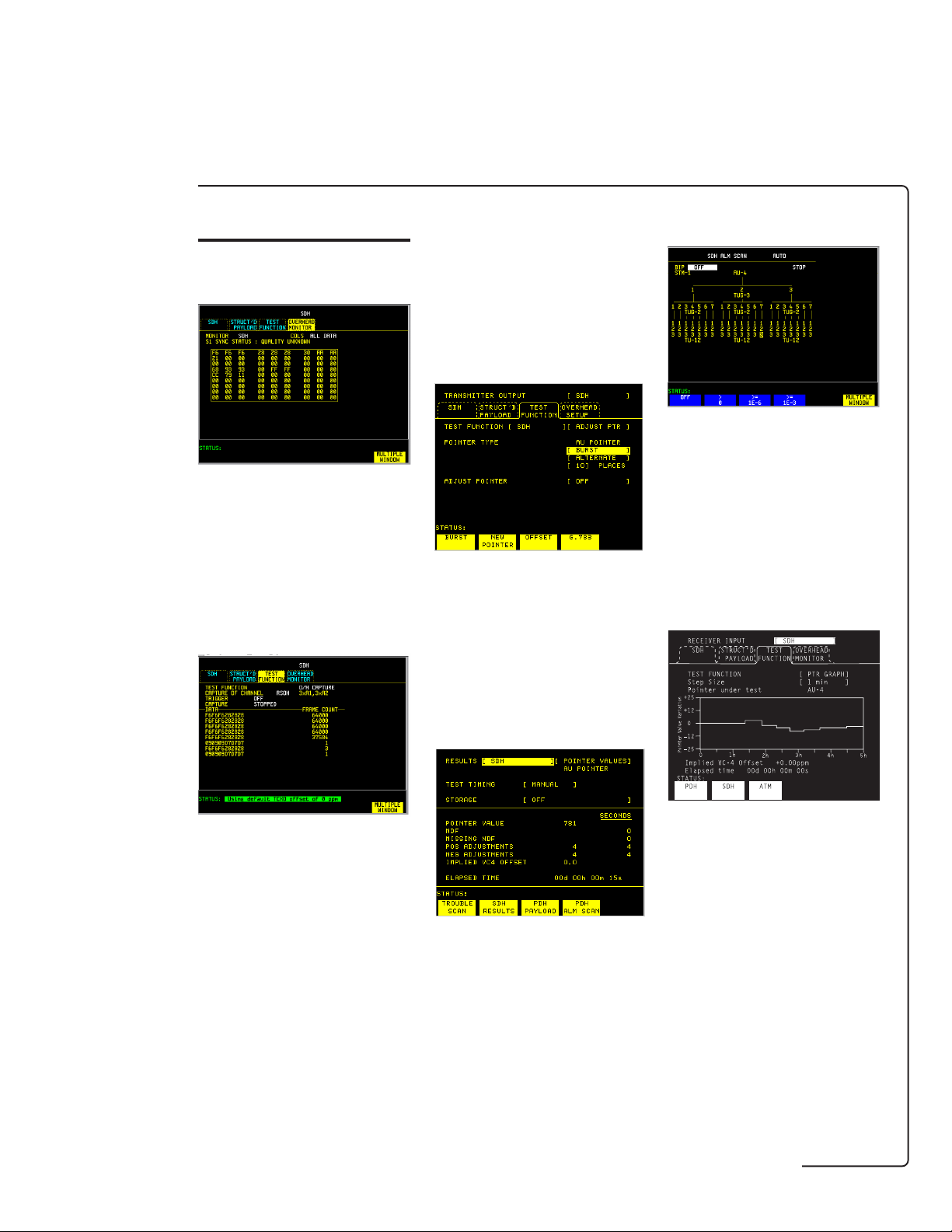
Overhead access
View the section and path
overhead bytes of a received
SDH signal. Bit by bit access of
transmitted section and path
overhead bytes. Display in hex
or binary.
Overhead sequences
DCC drop and insert
Drop or insert RSOH and
MSOH DCC channels via the
SDH module's RS-449
connector.
Pointer adjustments and
analysis
Make positive and negative
adjustments with added and
canceled pointers as per
ITU-T G.783 plus 87:3 pointer
test sequence, then view the
AU and TU pointer value and
AU and TU positive and
negative adjustments.
SDH alarm scan
In-service SDH alarm and BIP
scan automatically scans all
TU-n tributaries within a
received STM-n signal allowing
fast sectionalization of faults.
Auto scan facilities
automatically determines the
received signal structure.
Pointer location graph
Overwrite static values in a
single overhead channel with a
single or repeated sequence of
user-defined values. Detect
intermittents by capturing
selected section and path
overhead channels.
Overhead BER
measurement
Perform a BER measurement
on a selected section or path
channel. Error count, error
ratio, error free seconds and %
error free seconds are
displayed.
Determine the synchronization
status of your network by
monitoring the received AU/TU
pointer value over time. Check
for wander problems or
excessive pointer movements.
PDH drop and insert
Drop/insert of 34/140/2 Mb/s to
or from an STM-1/STM-4
signal.
Thru mode
Use the STM-0/STM-1/STM-4
thru mode for in-service
monitoring where no protected
monitor points are available.
7

Mixed payloads
features
Generate mixed TU-3 and TU12 signal structures in order to
test network elements,
configured to carry mixed 2
Mb/s and 34 Mb/s traffic.
SDH tributary scan
Automatic verification of VC-n
paths within an ADM etc, using
the out-of-service tributary
scan for faster installation
testing.
SONET features
Overhead access
View the transport and path
overhead bytes of a received
SONET signal. Bit by bit access
of transmitted section and path
overhead bytes. Display in hex
or binary.
Overhead sequences
Overwrite static values in a
single overhead channel with a
single or repeated sequence of
user-defined values. Detect
intermittents by capturing
selected section and path
overhead channels.
Overhead BER
measurement
Perform a BER measurement
on a selected section, line or
path channel. Error count,
error ratio, error free seconds
and % error free seconds are
displayed.
DCC drop and insert
Drop or insert TOH and TOH
DCC channels via the SONET/
SDH module's RS-449
connector.
Pointer adjustments and
analysis
Make positive and negative
adjustments with added and
canceled pointers as per
ANSI T1.105.03 plus 87:3
pointer test sequence, then
view the SPE and VT pointer
value and SPE and VT positive
and negative adjustments.
SONET alarm scan
In-service SONET alarm and
BIP scan automatically scans
all VTn tributaries within a
received OC-n/STS-n signal
allowing fast sectionalization of
faults. Auto scan facilities
automatically determines the
received signal structure.
8

Pointer location graph
features
Determine the synchronization
status of your network by
monitoring the received SPE/
VT pointer value over time.
Check for wander problems or
excessive pointer movements.
DSn/PDH drop and insert
Drop/insert of DS1/DS3/2M to
or from an OC-3/OC-12 signal.
ATM features
Change cell stream bandwidth
to obtain quickly quality-ofservice data for the ATM
network.
A single ATM virtual channel
(VC) is set up as the
foreground test signal. The
remaining bandwidth is then
filled with background VCs and
idle or unassigned cells.
Cell delay
Thru mode
Use the OC-1/OC-3/OC/12 thru
mode for in-service monitoring
where no protected monitor
points are available.
Mixed payloads
Generate mixed STS-1 signal
structures within STS-3/OC-3
signal structures in order to
test network elements.
SONET tributary scan
Set cell content to ITU-T O.191
test cells for cell performance
measurements (eg, cell loss,
delay, misinsertion or errors),
PRBS or user defined pattern.
Channel View
Find and identify the VPI/VCI
of up to 1023 channels,
showing cell rates or
percentage for all found VCs;
VPI display filter, AAL type and
ATM alarms displayed against
each VC.
Graphical display for 1-point
and 2-point cell delay variation
(ITU-T I.356) and nonconforming cell count.
AAL monitoring
(AAL-1, AAL-3/4, AAL-5)
SAR-PDU counts/rate, CRC
errors, sequence errors, lost
cell count, aborted PDUs and
length errors.
Automatic verification of VTn
paths within an ADM etc, using
the out-of-service tributary
scan for faster installation
testing.
9

VC rate history
features
Graphical display of maximum,
mean and minimum cell rate on
a chosen VC for short or
extended periods (up to a
month).
Native LAN
Ethernet LAN interfaces; 'ping'
tests for lost packet counts;
round trip delay under
different load conditions.
Verification of file transfer and
transfer time.
Jitter features
Jitter tolerance
Use the automatic jitter
tolerance test to verify
network equipment's
performance margins relative
to ITU-T G.823 (PDH) and
G.958 (SDH) jitter masks.
Jitter transfer
Wander measurement
View current measurements in
graphical or text format on the
results display. Three +ve and
−ve sliding graphs, each
showing ± 1 UI, ± 16 UI and ±
256 UI are provided.
After installing a native LAN
over WAN service and before
handing over to the customer,
you'll want to be certain that
the service performs properly.
Using the provided IP protocol,
you can readily check latency
(delay) and connectivity in
such installations.
Jitter sweep
Automatic jitter transfer test
(with narrow bandwidth
selective filtering) tests jitter
accumulation in regenerative
repeators etc.
Sweep the ITU-T G.823 (PDH)
and G.958 (SDH) jitter masks
to quickly check for jitter
tolerance problems. View the
progress of the jitter sweep on
the analyzer's display.
10
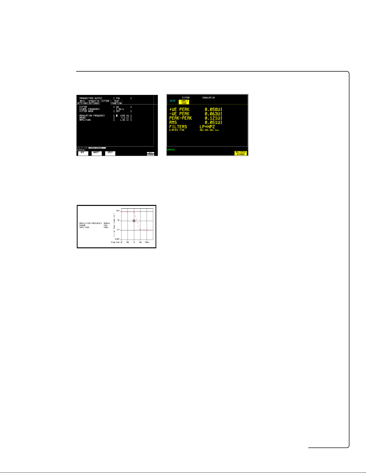
Spot frequency
features
Output jitter
Alternatively, reproduce and
further investigate those jitter
problems by generating a
specified amplitude of jitter at
a spot frequency.
The analyzer's display shows
the generated value of jitter
relative to the ITU.T mask.
Perform PDH and SDH ouput
jitter measurements to ITU-T
G.783, G.825 with ITU-T O.171
LP, HP1 and HP2 filters. RMS
jitter measurements to ITU-T
G.958 are also available with
additional 12 kHz HP filter.
11

Capability summary
SDH and DSn/PDH supported configurations
PDH/ATM cell test
and PDH interfaces
capability
Option UKK Page 14
Unstructured PDH: 0.7, 2, 8,
34 and 140 Mb/s.
Option UKJ Page 14
Structured PDH generation
and measurement: 2, 8, 34 and
140 Mb/s.
Option UKN Page 14, 53
ATM cell generation and
analysis: 2, 34 and 140 Mb/s
(includes all capability of
option UKJ structured PDH).
Option UH3 Page 73
Binary (NRZ) clock and data
Tx/Rx interfaces plus external
clock input. Must also order
option UKK, UKJ, UKN or 110.
Option UHC Page 76
Three additional 2, 8, 34 and
140 Mb/s outputs. Must also
order option UKK, UKJ or
UKN.
Option 110 Page 18
Structured: DS1, DS3,
E1, E3.
STM-0, STM-1e test
and interfaces
Option A3R Page 22
STM-0e (52 Mb/s) and
STM-1e (155 Mb/s) electrical
interface: STM-0/STM-1
overhead access, thru mode
and pointer sequence
generation and full ITU-T
G.707 mappings.
STM-1 and STM-4
interfaces
Option UH1 Page 29, 67
STM-1 (1310 nm).
Option 130 Page 30
Combined STM-0, STM-1 and
STM-4 (1310 and 1550 nm),
STM-0, STM-1 and STM-4
overhead access, optical
power measurement.
Option 131 Page 30
Combined STM-0, STM-1 and
STM-4 (1310 nm), STM-0,
STM-1 and STM-4 overhead
access, optical power
measurement.
Option 0YH Page 72
STM-0, STM-1 and STM-4
NRZ interfaces. Must also
order option 130 or 131.
(See Note 1)
Jitter, wander
and slips testing
Option A3K Page 40
PDH and SDH jitter and
wander generation.
Option 140 Page 40
PDH and SDH jitter
generation.
Option UHN Page 45
PDH jitter measurement:
2, 8, 34 and 140 Mb/s.
Option A3L Page 45
STM-1e line and PDH jitter
measurement: 2, 8, 34, 140
and 155 Mb/s.
Option A3V Page 45
STM-1o, STM-1e line and
PDH jitter measurement: 2, 8,
34, 140 Mb/s electrical and
155 Mb/s electrical and
optical.
Option A3N Page 45
STM-4o, STM-1o, STM-1e
line and PDH jitter
measurement: 2, 8, 34, 140
Mb/s electrical, 155 Mb/s
electrical and optical and
622 Mb/s optical.
Note 1: All optical interface modules require the STM-0e/STM-1e test and interface module (option A3R).
Dual standard SONET/SDH and DSn/PDH supported configurations
PDH/DSn interfaces
Option 110 Page 18
Structured: DS1, DS3, E1, E3.
Option UKK Page 14
Unstructured PDH: 0.7, 2, 8,
34 and 140 Mb/s.
Option UKJ Page 14
Structured PDH: 2, 8, 34 and
140 Mb/s.
Option UKN Page 14, 53
ATM cell: 2, 34 and 140 Mb/s
(includes all capability of option
UKJ).
Option UH3 Page 73
Binary (NRZ) clock and data
plus external clock input. Must
also order option UKK, UKJ,
UKN or 110.
Note 1: All optical interface modules require the SONET/SDH test and interface module
(option 120).
* Jitter capability does not include DS1/DS3. Synchronous line rate measurements are to
ITU-T specifications.
SONET/SDH
test and interfaces
Option 120 Page 34
STS-1/STM-0e (52 Mb/s) and
STS-3/STM-1e (155 Mb/s)
electrical interface: Overhead
access, thru mode and pointer
sequences. Full ITU-T G.707
and Bellcore G-253 mappings.
Optical
interfaces
Option UH1 Page 29, 67
155 Mb/s (1310 nm).
Option 130 Page 30
622/155/52 Mb/s optical
interface (1310 and
1550 nm), optical power
measurement.
Option 131 Page 30
622/155/52 Mb/s optical
interface (1310 nm), optical
power measurement.
Option 0YH Page 72
622/155/52 Mb/s binary (NRZ)
interfaces. Must also order
option 130 or 131.
(See Note 1)
Option A3K Page 40
PDH, 155 Mb/s, 622 Mb/s jitter
and wander generation.
Option 140 Page 40
As option A3K, but without
wander generation.
Option UHN Page 45
PDH jitter measurement.
Option A3L Page 45
155 Mb/s electrical and PDH jitter
measurement.
Option A3V Page 45
155 Mb/s optical, electrical and
PDH jitter measurement.
Option A3N Page 45
622 and 155 Mb/s optical,
electrical and PDH jitter
measurement.
Jitter, wander and slips
testing – generation*
Jitter, wander and slips
testing – measurement*
12

Broadband test plug-in modules
ATM cell test
and PDH interfaces
capability
Option UKN1Page 14, 53
ATM cell generation and
analysis: 2, 34 and 140 Mb/s
(includes all capability of
option UKJ structured PDH).
Option UKZ
Generation and measurement
of ATM payloads: 1.544
(DS1), 44.736 (DS3), 2.048
(E1) and 34.368 (E3) Mb/s.
1
ITU-T
2
ANSI/ITU-T
Option 0YK Page 60
Adds Channel View, graphical
display of CDV, AAL analysis,
rate history, benchmark
traffic generation. Must also
order option UKN or UKZ.
Option USL Page 60
Adds Ethernet LAN
connectivity testing plus all
features of option 0YK. Must
also order option UKN or
UKZ.
2
ATM services
layer test
Page 56
STM-1e test
and interfaces
Option A1T Page 63
STM-1e (155 Mb/s) electrical
interface from ATM testing.
Optical
interfaces
Option UH1 Page 29, 67
155 Mb/s (1310 nm).
Option USN Page 68
Combined STM-1 and STM-4
(1310 and 1550 nm) STM-1
and STM-4 overhead access,
optical power measurement.
Option UKT Page 68
Combined STM-1 and STM-4
(1310 nm), STM-1 and STM-4
overhead access, optical
power measurement.
Option UH3 Page 73
Binary (NRZ) clock and data
Tx/Rx interfaces plus
external clock input. Must
also order option UKK, UKJ
or UKN.
Jitter, wander
and slips testing
Option A3K Page 40
PDH and SDH jitter and
wander generation.
Option 140 Page 40
PDH and SDH jitter
generation.
Option UHN Page 45
PDH jitter measurement:
2, 8, 34 and 140 Mb/s.
Option A3L Page 45
STM-1e line and PDH jitter
measurement: 2, 8, 34, 140
and 155 Mb/s.
Option A3V Page 45
STM-1o, STM-1e line and
PDH jitter measurement: 2, 8,
34, 140 Mb/s electrical and
155 Mb/s electrical and
optical.
Option A3N Page 45
STM-4o, STM-1o, STM-1e
line and PDH jitter
measurement: 2, 8, 34, 140
Mb/s electrical, 155 Mb/s
electrical and optical and 622
Mb/s optical.
13

PDH
TRANSMIT
2 8 34 140 Mb/s
RECEIVE
2 8 34 140 Mb/s
Option UKK
Unstructured PDH: 0.7, 2, 8,
34 and 140 Mb/s.
Key to all tables
● = compliance
– = non-compliance
Option UKJ*
Pair of modules providing
structured PDH generation
and measurement: 2, 8, 34
OUT
PDH & DS1/DS3
MUX
IN
75Ω
DEMUX
HANDSET
75Ω
and 140 Mb/s.
Option UKN
Pair of modules providing
ATM cell generation and
analysis: 2, 34 and 140 Mb/s
(includes all capability of
option UKJ structured
Option
UKK
Option
UKJ
Option
UKN
PDH).
PDH test options Unstructured Structured
PDH PDH
UKK UKJ* , UKN
OUT and IN ports (used for transmit and receive)
Type Electrical: To ITU-T G.703. ●●
Connectors BNC, 75 ohm, unbalanced and Siemens 3-pin, ●●
Rate PDH: 704 kb/s. ● –
120 ohm balanced.
(Small Siemens 75 ohm unbalanced option available.)
PDH: 2.048, 8.448, 34.368 and 139.264 Mb/s. ●●
ATM: 2.048, 34.368, 139.264 and 155.52 Mb/s‡. – ●
‡ For ATM you require option UKN and for 155.52 Mb/s you
also require an STM-1 test option (option A3R or A1T).
PDH transmitter
Clock timing Internal: All rates. ●●
Frequency offset generation Up to ± 100 ppm in 1 ppm steps. ●●
Test pattern PRBS (to ITU-T O.151): 2
Output 704 kb/s: HDB3 or AMI balanced/unbalanced. ● –
Bit error add 1 in 103. ●●
Recovered (loop timed): From 704 kb/s input. ● –
Recovered (loop timed): From 2.048 Mb/s input. ●●
Recovered (loop timed): From 8.448, 34.368 and 139.264 Mb/s input. – ●
15
PRBS: 29 − 1, 211 − 1 and 220 − 1. – ●
Word: User-defined 16-bit word, all ones, all zeros, 1010, 1000. ●●
2.048 Mb/s: HDB3 or AMI balanced/unbalanced. ●●
8.448 Mb/s: HDB3 or AMI unbalanced. ●●
34.368 Mb/s: HDB3 unbalanced. ●●
139.264 Mb/s: CMI unbalanced. ●●
1 in 104, 1 in 105, 1 in 106 and 1 in 107. – ●
Single error. ●●
− 1 and 223 − 1. ●●
*Adding ATM (option UKN) capability to structured PDH (option UKJ) can be accomplished via a firmware upgrade.
14

PDH test options (continued) Unstructured Structured
PDH PDH
UKK UKJ, UKN
Frame error add 1 in 103, 1 in 104, 1 in 105, 1 in 106, 1 in 10
Code error add 2.048, 8.448, 34.368 Mb/s: 1 in 103, 1 in 104, 1 in 105, – ●
CRC4 error add 1 in 103, 1 in 104, 1 in 105, 1 in 106, 1 in 107 and single error. – ●
REBE error add 1 in 103, 1 in 104, 1 in 105, 1 in 106, 1 in 107 and single error. – ●
Alarm generation LOS, AIS, LOF, RAI, RMFAI, CASMFL. – ●
PDH & DS1/DS3
Spare bits generation The following spare bits may be modified: – ●
CAS signaling bits Modify the ABCD signaling bits (timeslot 16 CAS multiframe only). – ●
generation
Tx frame formats All rates: Unframed only. ● –
Test signal at any level N × 64 kb/s, 64 kb/s, 2.048, 8.448, 34.368 – ●
within signal structure and 139.264 Mb/s.
Test signal at interface 704 kb/s, 2.048, 8.448, 34.368 and 139.264 Mb/s. ● –
rate only
Background patterns Unframed 29 − 1 PRBS, AIS or same pattern as – ●
Ext 2 Mb/s mux input To ITU-T G.703, unbalanced HDB3 signal. – ●
and error one to four consecutive frames.
1 in 106, 1 in 107 and single error.
140 Mb/s: FAS bits 14 to 16.
34 Mb/s: FAS bit 12
8 Mb/s: FAS bit 12.
2 Mb/s Si bits (international bits): Timeslot 0 bit 1 in both FAS
and NFAS frames.
2 Mb/s E bits: CRC4 frames 13 and 15; timeslot 0 bit 1.
2 Mb/s Sa bit (national bits): NFAS timeslot bits 4 to 8 .
2 Mb/s Sa bit sequences: An 8 bit sequence may be transmitted
in any selected NFAS Sa bit when CRC4 framing has been
selected. The sequence appears in odd-numbered CRC4 frames,
starting at frame 1.
2 Mb/s CAS multiframe: MFAS timeslot bits 5, 7 and 8.
All rates: Unframed, framed and structured. – ●
2.048 Mb/s: To ITU-T G.706 and G.732 – ●
(No MFM, CAS, CRC4 MFM, CAS + CRC4 MFM).
2.048 Mb/s: N × 64 kb/s to ITU-T G.704. – ●
8.448 Mb/s: To ITU-T G.742. – ●
34.368, 139.264 Mb/s: To ITU-T G.751. – ●
foreground test signal.
7
– ●
PDH receiver
Jitter tolerance To ITU-T O.171. ●●
Equalization at f/2 To ITU-T G.703. ●●
Monitor point compensation 704 kb/s. 26 to 30 dB –
Frame formats All rates: Unframed and framed. ●●
704 kb/s. 6 dB –
2.048, 8.448 Mb/s. 6 dB 6 dB
34.368, 139.264 Mb/s. 12 dB 12 dB
2.048, 8.448 Mb/s. 26 to 30 dB 20, 26 or 30 dB
34.368, 139.264 Mb/s. 26 dB 20 or 26 dB
All rates: Structured. – ●
2.048 Mb/s: To ITU-T G.706 and G.732 ●●
(No MFM, CAS, CRC4 MFM, CAS + CRC4 MFM).
2.048 Mb/s: N × 64 kb/s to ITU-T G.704. – ●
8.448 Mb/s: To ITU-T G.742. ●●
34.368, 139.264 Mb/s: To ITU-T G.751. ●●
15

PDH test options (continued) Unstructured Structured
PDH PDH
UKK UKJ, UKN
Frequency measurement Frequency displayed in Hz, 1 Hz resolution. ●●
Ext. 2 Mb/s demux output Nominally to ITU-T G.703, unbalanced HDB3 signal only. – ●
Autosetup Bit rate, code, framing and level of incoming signal. ●●
Errors (out-of-service ) Error count and ratio: Bit, code. ● –
Errors (ISM only†) Error count and ratio: Code, frame. ● –
PDH & DS1/DS3
Errors Error count and ratio: Bit, code, frame. – ●
Alarm indication AIS, LOS, pattern sync loss, errors present. ●●
(out-of-service)
Alarm seconds As for alarm indication above, plus power loss. ●●
(out-of-service)
Alarm indication All rates: AIS, frame loss, LOS, pattern sync loss, ● –
(ISM only†) remote alarm, errors present;
Alarm seconds As for alarm indication above, plus power loss. ● –
(ISM only†)
Alarm indication All rates: AIS, frame loss, LOS, pattern sync loss, – ●
Alarm seconds As for alarm indication above, plus power loss. – ●
G.821 analysis (Bit): EC, SES, %SES, ES, %ES, EFS, %EFS, ● –
(out-of-service) unavailability, %unavailability, degraded minutes,
G.821 analysis (Frame, CRC, REBE): EC, SES, %SES, ES, %ES, EFS, ● –
(ISM only†) %EFS, unavailability, %unavailability, degraded minutes,
G.821 analysis (Bit, frame, CRC, REBE): EC, SES, %SES, ES, %ES, – ●
G.826 analysis Errored blocks (EB), errored seconds (ES), severely errored – ●
(CRC, REBE) seconds (SES), unavailable second count (UAS),
M.2100 error analysis Same as G.821 (bit errors only). ● –
(out-of-service)
M.2100 error analysis (Frame, CRC, REBE): Tx ES, Tx SES, Rx ES, Rx SES, ● –
(ISM only†) unavailability.
M.2100 error (Bit frame, CRC, REBE): Tx ES, Tx SES, Tx UNAV, Rx ES, – ●
analysis Rx SES, Rx UNAV.
M.2110 bringing into 2 hour, 24 hour and 7 day PASS/–?–/FAIL indication. – ●
service test Run a 24 hour out-of-service test using a PRBS. After
Offset displayed in ppm and Hz.
Test pattern for unframed and framed signals.
CRC4 (2.048 Mb/s only),
REBE (2.048 Mb/s only).
2 Mb/s: CAS/CRC multiframe loss, remote multiframe alarm.
remote alarm, minor alarm, errors present;
2 Mb/s: CAS/CRC multiframe loss,
remote multiframe alarm.
%degraded minutes, code error seconds, elapsed time
(including Annex D).
%degraded minutes, code error seconds,
elapsed time.
EFS, %EFS, unavailability, %unavailability,
degraded minutes, %degraded minutes, code error seconds,
elapsed time (including Annex D for bit errors).
path unavailable second count (PUAS), background block
error count (BBE), errored second ratio (ESR), severely
errored second ratio (SESR), background block error
ratio (BBER).
24 hours the instrument compares ES, SES and UAS results
against the S1 and S2 thresholds derived from the path
allocation and flags either PASS/–?–/FAIL. The 7 day
test is then performed on uncertain paths (–?–) during
the 24 hour test, ie, run contiguously for a further 6 days.
† ISM = In-service measurement mode on framed signals (unstructured PDH option UKK).
16

PDH test options (continued) Unstructured Structured
PDH PDH
UKK UKJ, UKN
M.2120 in-service test Contiguous 15 minute (T1) and 24 hour (T2) periods – ●
for maintenance with TR1 and TR2 threshold reports. Based on the user
entered path allocation and maintenance factors, the
T1-ES, T1-SES, T2-ES and T2-SES thresholds are
calculated. A single threshold report (TR1 for 15 minute,
TR2 for 24 hour) is generated when any of the relevant
thresholds are exceeded within each 15 minute or
24 hour period.
PDH & DS1/DS3
Spare bit display At all rates. NFAS (2 Mb/s), multiframe sync (2.048 Mb/s CAS), ● –
(ISM only†) FAS (8.448, 34.368 to 139.264 Mb/s).
Error output One pulse per bit error or code error. ● –
Round trip delay Up to 2 seconds delay between transmit and receive. – ●
Alarm scan Automatically scans the PDH network hierarchy – ●
CAS signaling Displays the ABCD signaling status of all 30 timeslots – ●
bit monitor (timeslot 15 CAS multiframe only).
N ´ 64 kb/s To ITU-T G.704; 1 to 31 contiguous and – ●
Telephone handset Provides full talk/listen capability – RJ11 connector – ●
connection (Telephone handset accessory available – HP 15722A).
† ISM = In-service measurement mode on framed signals (unstructured PDH option UKK).
Nominal ECL, 75 ohm −2 V BNC.
for alarms (frame loss, AIS and remote alarms).
non-contiguous timeslots.
17

DS1/DS3/E1/E3 structured test interfacing
Option 110
Pair of modules providing structured
DSn and PDH generation and
measurement at DS1 (1.5 Mb/s),
DS3 (45 Mb/s) and E1 (2 Mb/s),
E3 (34 Mb/s ).
PDH & DS1/DS3
Option 110
DS1/DS3/E1/E3 structured test interfaces Structured
DSn/PDH
110
OUT and IN ports (used for transmit and receive)
Type Electrical: To ANSI T1.102-1993; ITU-T O.171, G.703. ●
Connectors DS1 (1.554 Mb/s): WECO bantam, 100 ohm balanced. ●
Rate 1.544, 2.048, 34.368, 44.736 Mb/s. ●
DSn/PDH transmitter
Clock timing Internal: All rates; ●
Frequency offset generation Up to ± 100 ppm in 1 ppm steps. ●
Clock output Selected transmitter clock (internal or looped receiver clock) used ●
Line coding DS1: B8ZS, AMI. ●
Output level DS1: DSX-1, DS1-LO. ●
DS3 (44.736 Mb/s): BNC, 75 ohm, unbalanced.
E1 (2.048 Mb/s): BNC, 75 ohm, unbalanced and WECO bantam,
120 ohm balanced.
E3 (34.368 Mb/s): BNC, 75 ohm, unbalanced.
Recovered by the receiver.
to generated DS1/DS3/E1/E3 test output signal.
(BNC connector, externally terminated 50 ohm to ground).
DS3: B3ZS.
E1: AMI, HDB3.
E3: HDB3.
DS3: DS3-HI, DSX-3, DS3-900'
18

DS1/DS3/E1/E3 structured test interfaces (continued) Structured
DSn/PDH
110
Framing All rates: Unframed, framed and structured. ●
PDH & DS1/DS3
Test pattern PRBS: 29 – 1, 2
Error add DS1: Bit, FAS (Frame Alignment Signal), BPV/code, CRC-6, EXZ (excess zeros). ●
Error insertion rate Single. ●
Alarm generation DS1: Loss of signal (LOS); Out of frame (OOF); alarm indication signal (AIS); ●
FEAC code generation With C-Bit parity framing loopback and alarm/status codes as per ●
Spare bits generation The following spare bits can be modified; ●
Signaling bits generation DS1: User selectable Signaling ON or OFF. When ON user selectable ●
DS1: SF (D4), SLC-96.
DS1: ESF to ANSI T1.403-1989, Bellcore TR-TSY-000499 and ITU-T G.704;
the ESF data link (DL) defaults to repetition of idle code (01111110).
DS3: M13 to ANSI T1.107-1995.
DS3: C-bit parity to ANSI T1.107a-1990.
E1: To ITU-T G.706/G.732.
E3: To ITU-T G.751.
N × 64 kb/s structured to ITU-T G.704 for E1, E3
N × 64 kb/s and N x 56 kb/s structured for DS1 and DS3.
11
15
20
– 1, 2
QRSS (DS1 only).
3-in-24 stress pattern (DS1 only).
Word: 1010, 1000, 16 bit user word, all ones, all zeros.
The PRBS polarity of patterns is user selectable.
DS3: Bit, FAS, MFAS (MultiFrame Alignment Signal), BPV/code, parity(P bits),
CP (path parity), FEBE, EXZ (excess zeros).
E1: Bit, FAS, BPV/code, CRC-4, REBE.
E3: Bit, FAS, BPV/code.
1.0E – 3.
1.1E – 3.
1.0E – 4 to 9.9E-9. Mantissa step size 0.1, exponent step size 1.
remote alarm indication (RAI).
DS3: LOS; LOF; AIS; RAI; far end alarm and control (FEAC): As per T1.107-1995.
E1: LOS, LOF, AIS, RAI.
E3: LOS, LOF, AIS, RAI.
ANSI T1.107-1995 can be generated.
Loopback codes: A single burst of N loopback codes and M messages
where N and M are in the range 1 through 15.
Alarm/status codes: Any ANSI T1.107-1995 message or any
0xxxxxx011111111, message where x is selectable, may be transmitted
either in a single burst of 1 to 15 times or continuously.
34 Mb/s: FAS bit 12
2 Mb/s Si bits (international bits): Timeslot 0 bit 1 in both FAS
and NFAS frames.
2 Mb/s E bits: CRC4 frames 13 and 15; timeslot 0 bit 1.
2 Mb/s Sa bit (national bits): NFAS timeslot bits 4 to 8 .
2 Mb/s Sa bit sequences: An 8 bit sequence may be transmitted
in any selected NFAS Sa bit when CRC4 framing has been
selected. The sequence appears in odd-numbered CRC4 frames, starting at frame 1.
2 Mb/s CAS multiframe: MFAS timeslot bits 5, 7 and 8.
AB bits for SF, ABCD for ESF and AB bits for SLC-96 framing.
– 1, 2
23
– 1, 2
– 1 . ●
Background patterns Unframed 29 – 1 PRBS, AIS or same as test pattern as foreground ●
test signal.
Ext DS1 mux input Weco bantam connector, AMI or B8ZS. ●
Ext 2 Mb/s mux input BNC to ITU-T G.703, AMI or B8ZS. ●
19

DS1/DS3/E1/E3 structured test interfaces (continued) Structured
DSn/PDH receiver
Type, connectors, rates, As for DSn/PDH transmitter. ●
line code and framing
Jitter tolerance To Bellcore TR-TSY-000009 (DS1/DS3) and ITU-T O.171. ●
Operating level (terminate) User selectable as follows: ●
PDH & DS1/DS3
Monitor point DS1 (balanced), E1 (balanced and unbalanced): 20, 26 or 30 dB gain relative ●
compensation to terminate mode. E1 (balanced) is restricted to half cable length with
Framing All rates: Unframed , framed and structured. ●
Frequency measurement Frequency displayed in Hz, 1 Hz resolution. ●
Error results DS1 (counts & ratios): Bit, B8ZS/AMI code violations, frame errors, CRC6 errors. ●
Alarm indication DS1:LOS, pattern loss, AIS, OOF, Multiframe Loss, RAI, EXZ, Idle ●
FEAC code indication With C-Bit parity framing loopback and alarm/status codes are decoded
G.826 analysis Errored blocks (EB), errored seconds (ES), severely errored ●
G.821 analysis EC, SES, %SES, ES, %ES, EFS, %EFS, unavailability, %unavailability, ●
M.2100 analysis Tx ES, Tx SES, Rx ES, Rx SES, unavailability ●
M.2110 bringing into 2 hour, 24 hour and 7 day PASS/–?–/FAIL indication. ●
service test Run a 24 hour out-of-service test using a PRBS. After
DS1 (balanced): DSX-1 to DS1-LO levels.
DS3 (unbalanced): DS3-HI, DSX-3 and DS3-900 levels.
E1 (balanced): 3.0 V ± 20% for cable lengths as per ITU-T G.703.
E1 (unbalanced): 2.37 V ± 20% for cable lengths as per ITU-T G.703.
E3 (unbalanced): 1.0 V ± 20% with automatic equalization for cable lengths
as per ITU-T G.703.
respect to ITU-T G.703 for 26 and 30 dB gains.
DS3 and E3: 20 or 26 dB gain relative to terminate mode.
DS1: SF (D4), SLC-96.
DS1: ESF to ANSI T1.403-1989, Bellcore TR-TSY-000499 and ITU-T G.704.
DS3: M13 to ANSI T1.107-1995.
DS3: C-bit parity to ANSI T1.107a-1990.
E1: To ITU-T G.706/G.732
E3: To ITU-T G.751
N × 64 kb/s structured to ITU-T G.704 for E1, E3
N × 64 kb/s and N x 56 kb/s structured for DS1 and DS3.
Offset displayed in ppm and Hz.
DS3 (counts & ratios): Bit, B3ZS code violations, frame errors, P-parity,
CP-parity, FEBE.
E1 (counts & ratios): Bit, HDB3/AMI code violations, frame errors,
CRC4, REBE.
E3 (counts & ratios): Bit, HDB3 code violations, frame error.
DS3:LOS, Pattern loss, AIS, OOF, Multiframe Loss, RAI, EXZ, Idle
E1: LOS, Pattern loss, AIS, LOF, RAI, RMFAI, CASMFL
E3: LOS, Pattern loss, AIS, LOF, RAI
and displayed. Displays shows current and last active FEAC message. ●
seconds (SES), unavailability seconds (UAS), error second ratio (ESR),
severely errored second ratio (SESR), background block error ratio (BBER),
path unavailable seconds (PUAS).
degraded minutes, (%) degraded minutes, code error seconds,
elapsed (including Annex D for bit errors)
24 hours the instrument compares ES, SES and UAS results
against the S1 and S2 thresholds derived from the path
allocation and flags either PASS/–?–/FAIL. The 7 day
test is then performed on uncertain paths (–?–) during
the 24 hour test, ie, run contiguously for a further 6 days.
DSn/PDH
110
20

DS1/DS3/E1/E3 structured test interfaces (continued) Structured
M.2120 in-service test Contiguous 15 minute (T1) and 24 hour (T2) periods ●
for maintenance with TR1 and TR2 threshold reports. Based on the user
PDH & DS1/DS3
Signaling monitor DS1: Signaling bit state is displayed. ABCD format for ESF and ●
Alarm scan Alarms at the Interface Rate and at all lower levels in the hierarchy ●
entered path allocation and maintenance factors, the
T1-ES, T1-SES, T2-ES and T2-SES thresholds are
calculated. A single threshold report (TR1 for 15 minute,
TR2 for 24 hour) is generated when any of the relevant
thresholds are exceeded within each 15 minute or
24 hour period.
AB for SF/SLC-96. SLC-96 can display one of three states;
0,1 or alternating.
E1: Graphical display, simultaneously showing the ABCD
signalling status of all 30 channels is available.
are scanned continuously. A graphical picture of the hierarchy is shown
which displays the alarm state for all streams.
DSn/PDH
110
21

STM-0/STM-1e test and interfacing
SDH
Option A3R
STM-0e (52 Mb/s) and STM-1e (155 Mb/s)
electrical interface: STM-0/STM-1 overhead
access, thru mode and pointer sequence
generation. Full ITU-T G.707 mappings plus
frequency offset generation, alarm and error
generation/detection plus an error output, SDH
alarm and BIP scan, tributary scan and protection
switch times.
Option A3R
SDH ITU-T G.707 mapping structure
22

SDH
STM-0/STM-1e test and interfacing options (continued) STM-0/STM-1e
testing
A3R
OUT and IN ports (used for transmit)
Type Electrical: To ITU-T G.703. ●
Connectors BNC, 75 ohm, unbalanced. ●
Rate 155.52 Mb/s. ●
Line code 155.52 Mb/s: CMI. ●
Output level 155.52 Mb/s: ± 0.5 V ± 10%. ●
Error output B3 error output pulse on receipt of STM-0 and STM-1 signals. ●
Simultaneous STM-1e/ When used in conjunction with the appropriate optical interfaces, ●
STM-1e and STM-1o transmit STM-1 electrical output signal simultaneously with
Transmitter
Clock timing Internal: All rates. ●
Frequency offset Up to ± 999 ppm in 0.1 ppm steps. ●
generation
Error addition ●
(Small Siemens 75 ohm unbalanced option available.)
51.84 Mb/s. ●
51.84 Mb/s: B3ZS. ●
51.84 Mb/s: ●
Output level is user configurable.
STM-0 X CON: 1.1 V peak nominal (0 ft).
STM-0 HI: 530 mV peak nominal (450 ft).
STM-0 LOW: 350m V peak nominal (900 ft).
TTL pulse termination 75 ohm or 10 kohm.
STM-1 optical output signal.
Recovered: From SDH input (CMI or NRZ electrical or optical). ●
Ext MTS: 64 kb/s conforming to ITU-T G.703, 2 Mb/s conforming to ITUT-G.811. ●
BNC, 75 ohm, unbalanced or Siemens (3-pin), 120 ohm, balanced. ●
(Siemens (3-pin) connector is present on option A3R.
Option 120 replaces this connector with a Bantam connector).
Error type Single Rate 10
Frame A1A2 ● N in four
B1 ● 4 to 9
B2† ● 3 to 9
MS REI ● 3 to 9
AU-4 path BIP-8 (B3) ● 4 to 9
AU-4 path REI ● 4 to 9
AU-4 path IEC ● 4 to 9
AU-3 path BIP-8 (B3) ● 4 to 9
AU-3 path REI ● 4 to 9
AU-3 path IEC ● 4 to 9
TU-3 path BIP-8 (B3) ● 3 to 9
TU-3 path REI ● 3 to 9
TU-2 path BIP (V5) ● 4 to 9
TU-2 path REI ● 5 to 9
TU-12 path BIP (V5) ● 3 to 9
TU-12 path REI ● 4 to 9
TU-11 path BIP ● 3 to 9
TU-11 path REI ● 4 to 9
Bit error* ● 3 to 9
-N
Comments
frame words
† MSP threshold N errors in T ms
where 0 ≤ N ≤ 1920 (STM-1) and
10 ms ≤ T ≤ 10000 s, in decade
steps.
* For SDH stand-alone operation,
bulk-filled payloads and DS1, DS3
mapped payloads only. For bit
error rates supported with other
payloads refer to the PDH test
option for details.
23

SDH
STM-0/STM-1e test and interfacing options (continued) STM-0/STM-1e
testing
A3R
Alarm generation LOS, LOF, OOF, MS AIS, MS RDI, ●
Payload capability
STM-0/STM-1/STM-4 139.264 Mb/s into a VC-4 and VC-4 bulk-filled mappings. ●
payload mappings 34.368 Mb/s into VC-3 and VC-3 bulk-filled mappings.
(to ITU-T G.707) 2.048 Mb/s (async and fl. byte sync) into VC-12 and VC-12 bulk-filled mappings.
Payload data The following unframed patterns can be generated:
Payload framing 139.264, 34.368 and 2.048 Mb/s: Unframed. ●
Drop/insert 139.264Mb/s: Drop/insert via Tx/Rx on options UKJ/UKN. ●
AU-4 path AIS, AU-4 path RDI, AU-4 LOP, AU-4 path unequipped,
AU-3 path AIS, AU-3 path RDI, AU-3 LOP, AU-3 path unequipped,
TU-3 path AIS, TU-3 path RDI, TU-3 LOP, TU-3 path unequipped,
TU-2 path AIS, TU-2 path RDI, TU-2 LOP, TU-2 path unequipped,
TU-2 H4 LOM (loss of multiframe),
TU-12 path AIS, TU-12 path RDI, TU-12 LOP, TU-12 path unequipped,
TU-12 H4 LOM (loss of multiframe),
TU-11 path AIS, TU-11 path RDI, TU-11 LOP, TU-11 path unequipped,
TU-11 H4 LOM (los of multiframe).
DS3 (44.736 Mb/s) into VC-3 and VC-3 bulk-filled mappings†
DS1 (1.544 Mb/s) async into VC-11†.
VC-3 - TU-3 - TUG-3 - VC-4 - AU-4;
VC-3 - AU-3.*
VC-2 bulk filled mapping and TU-2-Nc (for N = 2 to 6):
VC-2 - TU-2 - TUG-2 - TUG-3 - VC-4 - AU-4.
VC-2 - TU-2 - TUG-2 - VC-3 - AU-3.*
VC-12 - TU-12 - TUG-2 - TUG-3 - VC-4 - AU-4.
VC-12 - TU-12 - TUG-2 - TUG-3 - VC-3 - AU-3.*
VC-11 - TU-11 - TUG-2 - TUG-3 - VC-4 - AU-4.†
VC-11 - TU-11 - TUG-2 - VC-3 - AU-3.*†
† DS1 and DS3 mappings require PDH options UKJ, UKN or 110 to be fitted.
* AU-3 mappings require HP OmniBER 717 analyzer mainframe.
(Framed and structured signals are available in conjunction
with the PDH/DSn option UKJ/UKN/110).
PRBS: 29 − 1 (O.150), 2
23
and 2
− 1 (O.151)
20
QRSS (2
Word: User-defined 16-bit word, all ones, all zeros, 1010, 1000.
All PRBS patterns can be set to inverted or non-inverted.
† Applicable to DS1 mappings only.
139.264, 34.368 and 2.048 Mb/s: Framed and structured†.
DS3 payloads: Unframed, C-Bit parity (to ANSI T1.107a-1990)†
M13 (to ANSI T1.107-1988).
TU-2: Unframed.
DS1 payloads: Unframed, SF (D4), ESF (to ANSI T1.403-1989,
TR-TSY-000499 and ITU-T G.704), SLC-96†.
† Only available in conjunction with the PDH/DSn option UKJ/UKN/110.
44.736 (DS3): Drop/insert via Tx/Rx on option 110.
34.368 Mb/s: Drop/insert via Tx/Rx on options UKJ/UKN/110.
2.048 Mb/s: Drop/insert via drop/insert ports on options UKJ/UKN/110.
1.544 Mb/s: Drop/insert via drop/insert ports on option 110.
− 1, 14 zero limited)†
11
− 1 (O.152), 2
15
− 1 (O.151) ●
24
 Loading...