

Page 1
Keysight ZA0060A
Custom IoT Device
Functional Test Solution
For Multi-up Configuration
Quick Start
Guide
Page 2

Notices
CAUTION
WARNING
Copyright Notice
© Keysight Technologies 2019
No part of this manual may be repro-
duced in any form or by any means
(including electronic storage and
retrieval or translation into a foreign
language) without prior agreement and
written consent from Keysight Technologies as governed by United States and
international copyright laws.
Trademarks
Bluetooth® and the Bluetooth® logos
are trademarks owned by Bluetooth
SIG, Inc., U.S.A. and licensed to
Keysight Technologies, Inc.
Manual Part Number
ZA0060-90001
Edition
Edition 1, December 2019
Printed in:
Printed in Malaysia
Published by:
Keysight Technologies
Bayan Lepas Free Industrial Zone,
11900 Penang, Malaysia
Technology Licenses
The hardware and/or software
described in this document are furnished under a license and may be
used or copied only in accordance with
the terms of such license.
Declaration of Conformity
Declarations of Conformity for this
product and for other Keysight products may be downloaded from the
Web. Go to http://www.keysight.com/
go/conformity. You can then search by
product number to find the latest Declaration of Conformity.
®
U.S. Government Rights
The Software is “commercial computer
software,” as defined by Federal Acquisition Regulation (“FAR”) 2.101. Pursuant to FAR 12.212 and 27.405-3 and
Department of Defense FAR Supplement (“DFARS”) 227.7202, the U.S.
government acquires commercial computer software under the same terms
by which the software is customarily
provided to the public. Accordingly,
Keysight provides the Software to U.S.
government customers under its standard commercial license, which is
embodied in its End User License
Agreement (EULA), a copy of which can
be found at http://www.keysight.com/
find/sweula. The license set forth in the
EULA represents the exclusive authority
by which the U.S. government may use,
modify, distribute, or disclose the Software. The EULA and the license set
forth therein, does not require or permit, among other things, that Keysight:
(1) Furnish technical information
related to commercial computer software or commercial computer software
documentation that is not customarily
provided to the public; or (2) Relinquish
to, or otherwise provide, the government rights in excess of these rights
customarily provided to the public to
use, modify, reproduce, release, perform, display, or disclose commercial
computer software or commercial computer software documentation. No
additional government requirements
beyond those set forth in the EULA
shall apply, except to the extent that
those terms, rights, or licenses are
explicitly required from all providers of
commercial computer software pursuant to the FAR and the DFARS and are
set forth specifically in writing elsewhere in the EULA. Keysight shall be
under no obligation to update, revise or
otherwise modify the Software. With
respect to any technical data as
defined by FAR 2.101, pursuant to FAR
12.211 and 27.404.2 and DFARS
227.7102, the U.S. government
acquires no greater than Limited Rights
as defined in FAR 27.401 or DFAR
227.7103-5 (c), as applicable in any
technical data.
Warranty
THE MATERIAL CONTAINED IN THIS
DOCUMENT IS PROVIDED “AS IS,”
AND IS SUBJECT TO BEING
CHANGED, WITHOUT NOTICE, IN
FUTURE EDITIONS. FURTHER, TO THE
MAXIMUM EXTENT PERMITTED BY
APPLICABLE LAW, KEYSIGHT DISCLAIMS ALL WARRANTIES, EITHER
EXPRESS OR IMPLIED, WITH REGARD
TO THIS MANUAL AND ANY INFORMATION CONTAINED HEREIN, INCLUDING BUT NOT LIMITED TO THE
IMPLIED WARRANTIES OF MERCHANTABILITY AND FITNESS FOR A
PARTICULAR PURPOSE. KEYSIGHT
SHALL NOT BE LIABLE FOR ERRORS
OR FOR INCIDENTAL OR CONSEQUENTIAL DAMAGES IN CONNECTION
WITH THE FURNISHING, USE, OR
PERFORMANCE OF THIS DOCUMENT
OR OF ANY INFORMATION CONTAINED HEREIN. SHOULD KEYSIGHT
AND THE USER HAVE A SEPARATE
WRITTEN AGREEMENT WITH WARRANTY TERMS COVERING THE MATERIAL IN THIS DOCUMENT THAT
CONFLICT WITH THESE TERMS, THE
WARRANTY TERMS IN THE SEPARATE
AGREEMENT SHALL CONTROL.
Safety Information
A CAUTION notice denotes a hazard. It
calls attention to an operating procedure, practice, or the like that, if not
correctly performed or adhered to,
could result in damage to the product
or loss of important data. Do not proceed beyond a CAUTION notice until
the indicated conditions are fully
understood and met.
A WARNING notice denotes a hazard. It
calls attention to an operating procedure, practice, or the like that, if not
correctly performed or adhered to,
could result in personal injury or death.
Do not proceed beyond a WARNING
notice until the indicated conditions are
fully understood and met.
2 Keysight ZA0060A Custom IoT Device Functional Test Solution Quick Start Guide
Page 3
Safety Symbols
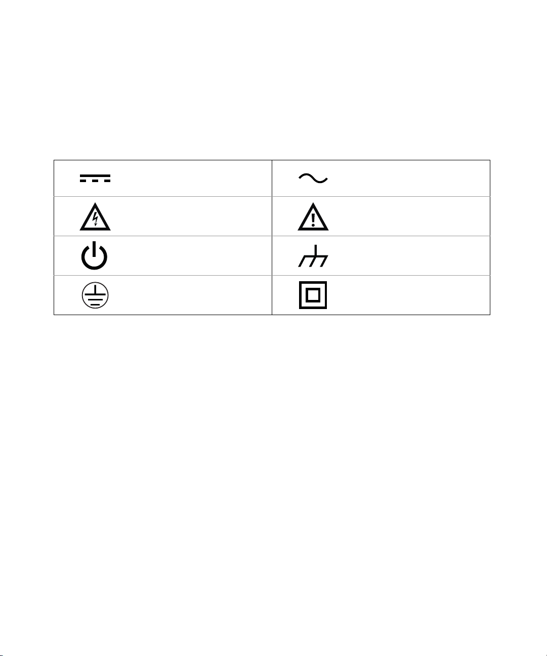
The following symbols on the instrument and in the documentation indicate
precautions which must be taken to maintain safe operation of the instrument.
Direct current (DC) Alternating current (AC)
Caution, risk of electric shock
Standby supply. Unit is not completely
connected from AC mains when
switched off
Protective earth (ground) terminal
Caution, risk of danger (refer to this
manual for specific Warning or Caution
information)
Frame or chassis (ground) terminal
Equipment protected throughout by
double insulation or reinforced
insulation
Keysight ZA0060A Custom IoT Device Functional Test Solution Quick Start Guide 3
Page 4

Safety Considerations
Read the information below before using this instrument.
The following general safety precautions must be observed during all phases of
operation, service, and repair of this instrument. Failure to comply with these
precautions or with specific warnings elsewhere in this manual violates safety
standards for design, manufacture, and intended use of the instrument. Keysight
Technologies assumes no liability for the customer’s failure to comply with these
requirements.
General
Do not use this product in any manner not specified by the manufacturer. The
protective features of this product may be impaired if it is used in a manner not
specified in the operation instructions.
Before Applying Power
Verify that all safety precautions are taken. Make all connections to the unit before
applying power and select the appropriate power line voltage on the fuse module.
Ground the Instrument
This product is provided with protective earth terminals. To minimize shock
hazard, the instrument must be connected to the ac power mains through a
grounded power cable, with the ground wire firmly connected to an electrical
ground (safety ground) at the power outlet. Any interruption of the protective
(grounding) conductor or disconnection of the protective earth terminal will cause
a potential shock hazard that could result in personal injury.
Do Not Operate in an Explosive Atmosphere
Do not operate the instrument in the presence of flammable gases or fumes.
Do Not Remove the Instrument Cover
Only qualified, service-trained personal who are aware of the hazards involved
should remove instrument covers. Always disconnect the power cable and any
external circuits before removing the instrument cover.
Keysight ZA0060A Custom IoT Device Functional Test Solution Quick Start Guide 4
Page 5

Do Not Modify the Instrument
Do not install substitute parts or perform any unauthorized modification to the
product. Return the product to a Keysight Sales and Service Office for service and
repair to ensure that safety features are maintained.
In Case of Damage
Instruments that appear damaged or defective should be made inoperative and
secured against unintended operation until they can be repaired by qualified
service personnel.
Keysight ZA0060A Custom IoT Device Functional Test Solution Quick Start Guide 5
Page 6

Safety and Regulatory Information
The ZA0060A complies with the following safety and Electromagnetic
Compatibility (EMC) regulations:
Safety compliance
– IEC 61010-1:2010/EN 61010-1:2010; IEC 61010-2-030:2010/
EN61010-2-030:2010
– Canada: CAN/CSA-C22.2 No.61010-1-12; CAN/CSA-C22.2 No.
61010-2-030-12
– USA: ANSI/UL Std. No. 61010-1:2012; ANSI/UL Std No.61010-2-030:2012
EMC regulation
– IEC 61326-1:2012 / EN 61326-1:2013
– Canada: ICES/NMB-001:2006
– Australia/New Zealand: AS/NZS CISPR 11:2011
Keysight ZA0060A Custom IoT Device Functional Test Solution Quick Start Guide 6
Page 7
Regulatory Markings
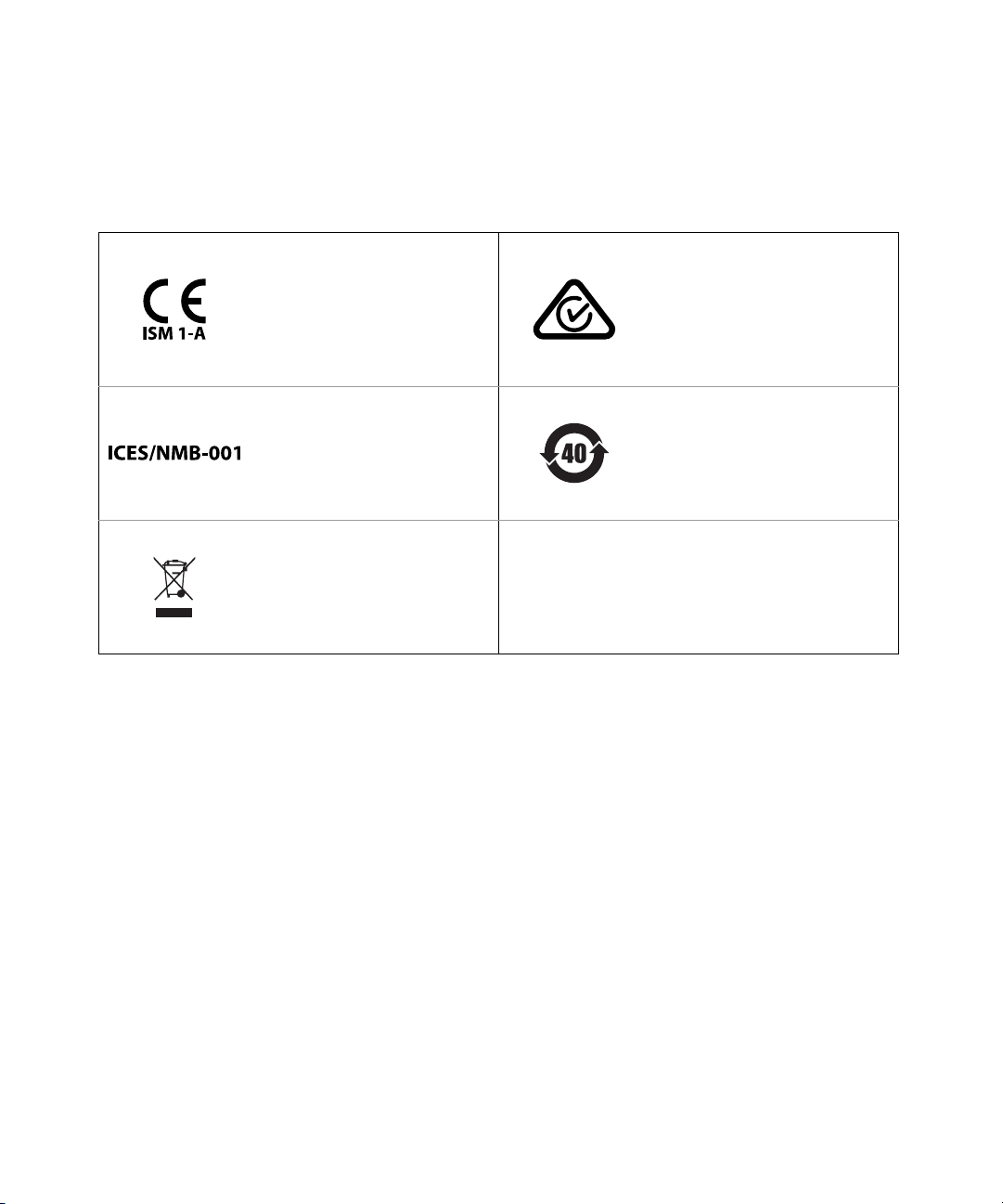
The CE mark is a registered trademark
of the European Community. This CE
mark shows that the product complies
with all the relevant European Legal
Directives.
ICES/NMB-001 indicates that this ISM
device complies with the
Canadian ICES-001.
Cet appareil ISM est conforme a la
norme NMB-001 du Canada.
This instrument complies with the
WEEE Directive (2002/96/EC) marking
requirement. This affixed product label
indicates that you must not discard
this electrical or electronic product in
domestic household waste.
The RCM mark is a registered
trademark of the Spectrum
Management Agency of Australia.
This signifies compliance with the
Australia EMC Framework regulations
under the terms of the Radio
Communication Act of 1992.
This symbol indicates the time period
during which no hazardous or toxic
substance elements are expected to
leak or deteriorate during normal use.
Forty years is the expected useful life
of the product.
Keysight ZA0060A Custom IoT Device Functional Test Solution Quick Start Guide 7
Page 8
Waste Electrical and Electronic Equipment (WEEE) Directive 2002/96/EC
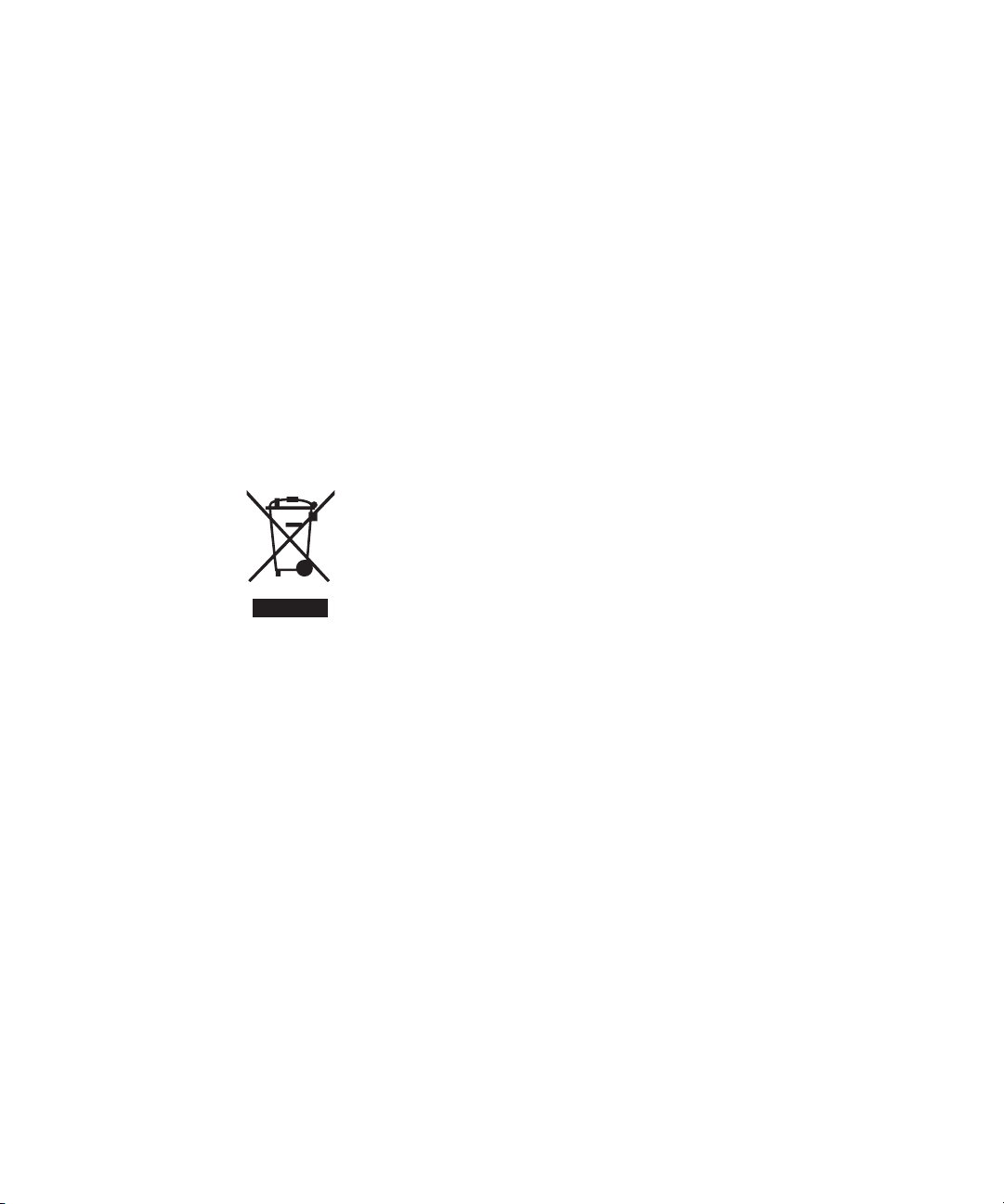
This instrument complies with the WEEE Directive (2002/96/EC) marking
requirement. This affixed product label indicates that you must not discard this
electrical or electronic product in domestic household waste.
Product category
With reference to the equipment types in the WEEE directive Annex 1, this
instrument is classified as a “Monitoring and Control Instrument” product.
The affixed product label is as shown below.
Do not dispose in domestic household waste.
To return this unwanted instrument, contact your nearest Keysight Service Center,
or visit http://about.keysight.com/en/companyinfo/environment/takeback.shtml
for more information.
Keysight ZA0060A Custom IoT Device Functional Test Solution Quick Start Guide 8
Page 9

Sales and Technical Support
To contact Keysight for sales and technical support, refer to the support links on
the following Keysight websites:
– www.keysight.com/find/X8711A
(product-specific information and support, software and
documentation updates)
– www.keysight.com/find/assist
(worldwide contact information for repair and service)
Keysight ZA0060A Custom IoT Device Functional Test Solution Quick Start Guide 9
Page 10

THIS PAGE HAS BEEN INTENTIONALLY LEFT BLANK.
Keysight ZA0060A Custom IoT Device Functional Test Solution Quick Start Guide 10
Page 11

Table of Contents
Safety Symbols . . . . . . . . . . . . . . . . . . . . . . . . . . . . . . . . . . . . . . . . . . . . .3
Safety Considerations . . . . . . . . . . . . . . . . . . . . . . . . . . . . . . . . . . . . . . . .4
Safety and Regulatory Information . . . . . . . . . . . . . . . . . . . . . . . . . . . . .6
Safety compliance . . . . . . . . . . . . . . . . . . . . . . . . . . . . . . . . . . . . . . . .6
EMC regulation . . . . . . . . . . . . . . . . . . . . . . . . . . . . . . . . . . . . . . . . . . 6
Regulatory Markings . . . . . . . . . . . . . . . . . . . . . . . . . . . . . . . . . . . . . . . . .7
Waste Electrical and Electronic Equipment (WEEE) Directive
2002/96/EC . . . . . . . . . . . . . . . . . . . . . . . . . . . . . . . . . . . . . . . . . . . . . 8
Product category . . . . . . . . . . . . . . . . . . . . . . . . . . . . . . . . . . . . . . . . .8
Sales and Technical Support . . . . . . . . . . . . . . . . . . . . . . . . . . . . . . . . . .9
Introduction . . . . . . . . . . . . . . . . . . . . . . . . . . . . . . . . . . . . . . . . . . . . . .13
To Prepare Instrument for Use . . . . . . . . . . . . . . . . . . . . . . . . . . . . . . . .14
Equipment requirements . . . . . . . . . . . . . . . . . . . . . . . . . . . . . . . . . .14
Software requirements . . . . . . . . . . . . . . . . . . . . . . . . . . . . . . . . . . .14
Hardware Configuration . . . . . . . . . . . . . . . . . . . . . . . . . . . . . . . . . . . . .15
Software Installation . . . . . . . . . . . . . . . . . . . . . . . . . . . . . . . . . . . . . . . .17
TAP and Measurement Suite License Redemption . . . . . . . . . . . . . . . .19
TAP and Measurement Suite License Installation . . . . . . . . . . . . . . . . .22
Node-Locked License . . . . . . . . . . . . . . . . . . . . . . . . . . . . . . . . . . . .22
USB Portable License . . . . . . . . . . . . . . . . . . . . . . . . . . . . . . . . . . . .23
Getting Started: IoT Device Test Add-Ons Package . . . . . . . . . . . . . . . 29
Procedure to use USB Coaxial Switch Step (Method 1) . . . . . . . . . .29
Procedure to use USB Coaxial Switch Step (Method 2) . . . . . . . . . .34
Procedure to use 34901 Measurement . . . . . . . . . . . . . . . . . . . . . . .36
Record and export data . . . . . . . . . . . . . . . . . . . . . . . . . . . . . . . . . . . . .38
Troubleshooting and Error Messages . . . . . . . . . . . . . . . . . . . . . . . . . .39
Fail to switch RF path(s) with error code -4 . . . . . . . . . . . . . . . . . . . 39
Fail to switch RF path(s) with error code -2 . . . . . . . . . . . . . . . . . . . 39
No valid BLE/WLAN/Zigbee option license found. For license request
Keysight ZA0060A Quick Start Guide 11
Page 12

please contact Keysight Technologies Sales & Support. . . . . . . 40
Could not create '<Test step>': License required: KS8330xA or
KS8330xB . . . . . . . . . . . . . . . . . . . . . . . . . . . . . . . . . . . . . . . . . . . 40
12 Keysight ZA0060A Quick Start Guide
Page 13
Introduction
Keysight ZA0060A
Custom IoT Device Functional Test Solution Quick Start Guide
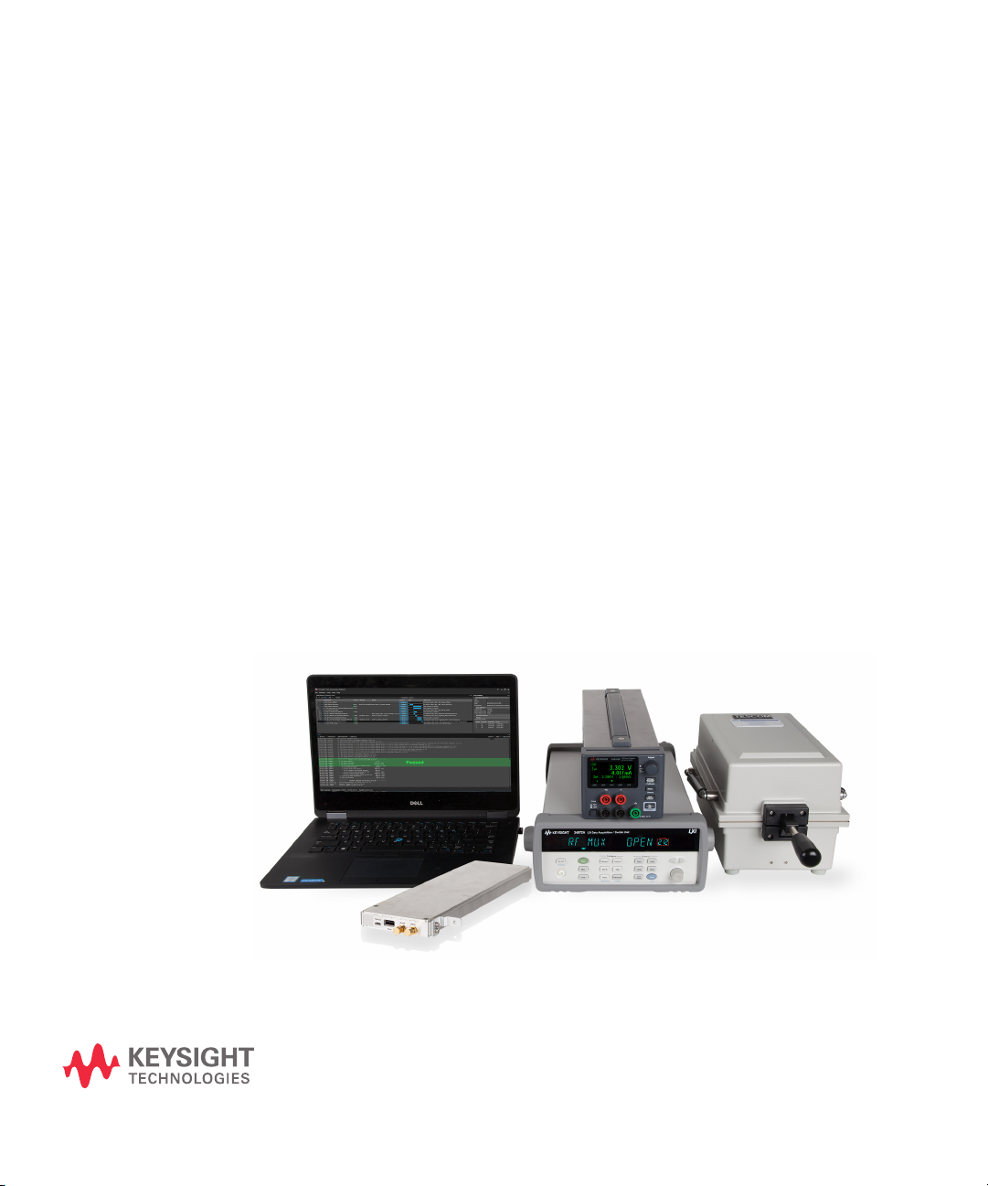
The Keysight ZA0060A is a custom solution based on the X8711A IoT device
functional test solution. It is an over-the-air signaling tester that enables you to
test your IoT device’s transmitter and receiver easily and effectively. It is as simple
as placing your device into a shield box and running the software test plans to get
the transmitter and receiver test results in seconds!
With ZA0060A, you can now extend your test coverage for Bluetooth
®
Zigbee® 3.0, on top of the existing Bluetooth
802.11b/g/n.
This Quick Start Guide is designed to guide you through the hardware and
software setup for the ZA0060A solution before introducing the features and
capabilities of the Zigbee 3.0 and Bluetooth
create and customize your test plan according to your test requirement.
With the use of a USB Coaxial Switch, you are now able to test up to two devices
under test (DUT) sequentially using one measurement system. The ZA0060A
solution supports the use U1810B and U1816A models of USB Coaxial Switch.
Low Energy 4.2 and WLAN
®
5 measurement suites. You can
®
5 and
13
Page 14
To Prepare Instrument for Use
NOTE
NOTE
NOTE
Equipment requirements
– Keysight 34972A LXI Data Acquisition / Switch Unit
– Keysight 34999B RF Module
– Keysight U1810B USB Coaxial Switch that comes with a N-type female to
female adaptor (1250-3274), a USB cable (8121-0506) and three RF cables.
– Power cord
– 34999-60009 USB cables Type A/B
– 34999-60011 USB cables Type A/Micro B
–RF cable*
–Shield box*
– Device under test (DUT)*
* These accessories are not included in the ZA0060A Custom IoT device
functional test solution.
Software requirements
– Keysight License Manager version 5.2 or above
For those who are using USB portable license, download and install Keysight
License Manager 6 at www.keysight.com/find/KLM6
– Keysight IO Libraries Suite version 18.0 or above
– Keysight Test Automation Platform (TAP) Software version 8.7
– KS8400A TAP Developer’s System or KS8000A TAP Deployment System
– Keysight 34999 Utility software version 2.1 or above
The KS8400A TAP Developer’s System will install Keysight License Manager if
not already installed.
14 Keysight ZA0060A Quick Start Guide
.
Page 15
Hardware Configuration
ii
i
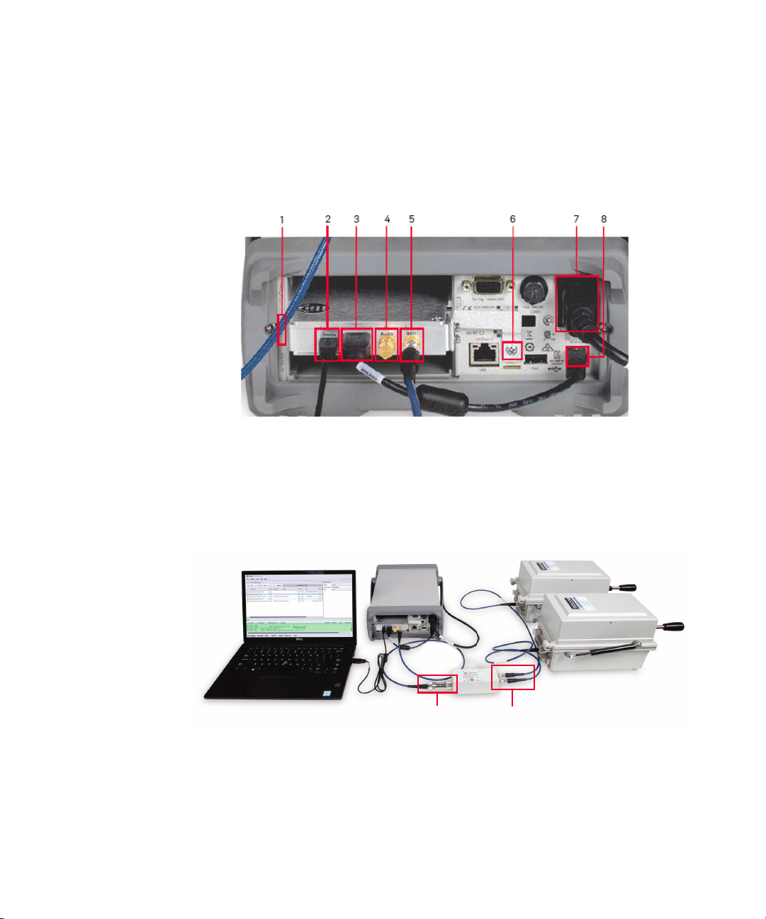
1 Attach the L locking bracket to the 34999B module and insert them into 1 (slot
200). Ensure that you have tightened the L locking bracket with a screw on 6
(Chassis Ground Screw).
2 Set up the connections below.
i 34999-60009 USB cable from 2 (Micro-USB Port) of 34999B RF
module to PC.
ii 34999-60011 USB cable from 3 (USB Port) to 8 (USB Interface
Connector) of the 34999B RF module.
3 For this step, refer to the connections of the U1810B switch as shown below.
i Connect the N-type female to female adapter (P/N 1250-3274) to the
common port of U1810B before connecting the RF cable from the
adapter to 5 (RFIO Port) of 34999B. Do not remove the terminator at 4
(AuxIO Port).
Keysight ZA0060A Quick Start Guide 15
Page 16
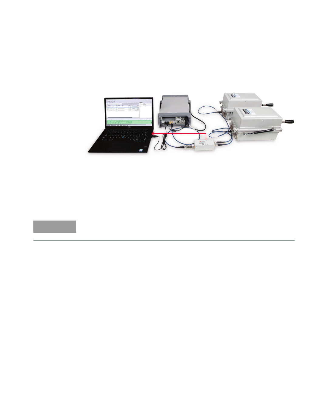
ii Connect the respective RF cables from the back of the shield boxes to
NOTE
Port 1 and 2 of U1810B switch.
4 Connect the U1810B cable (P/N 8121-0506) to the USB port on your PC as
indicated by the red arrow below. The LED indicator at Ports 1 or 2 will light up
once it is connected.
5 Plug in the power cord to 7 (Power Line Fuse Holder Assembly) and then to
the source of electricity.
6 Download and install the software listed in the next section, then power on the
34972A. Allow 15 seconds after powering on the 34972A for your PC to detect
the instrument and its VISA address.
Refer to the U1810B Operating and Service Manual for more information on
troubleshooting and calibration.
16 Keysight ZA0060A Quick Start Guide
Page 17
Software Installation
The Install wizard is a centralized application that contains necessary installers
and software packages for the ZA0060A solution. Download the latest Install
wizard to access the new releases of the software packages.
1 Download and install X8711A & ZA0060A Install wizard from
www.keysight.com/find/ZA0060A-installwizard.
2 Follow the on-screen instructions and click Finish to complete installation.
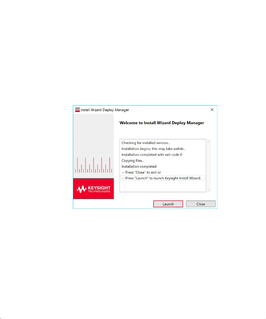
3 Click Launch when you see the pop-up below.
Keysight ZA0060A Quick Start Guide 17
Page 18
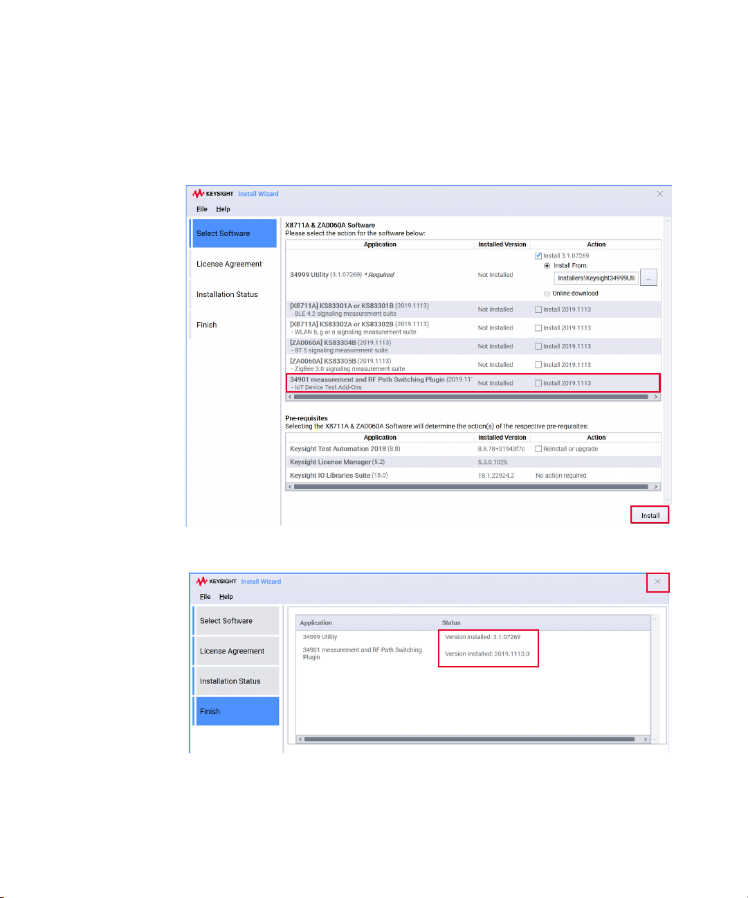
4 Select the Install 2019.1113 check box to install the IoT Device Add-Ons
package and software prerequisites in the ‘Action’ column as shown below. The
34999 Utility application is a compulsory software that will be selected by
default when it is not installed in your PC.
5 When the status reflects the latest version installed, you may close the Install
wizard. Next, proceed to redeem your licenses.
18 Keysight ZA0060A Quick Start Guide
Page 19
TAP and Measurement Suite License Redemption
NOTE
The KS8400A license is required to install the 34901 measurement and RF path
switching plugin (IoT Device Test Add-Ons) package for the X8753A multi-up
configuration.
1 Refer to the email or printed Keysight License Entitlement Certificate for
instructions on how to redeem your license.
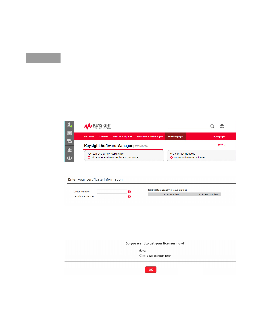
2 Log in to Keysight Software Manager (KSM) using your myKeysight account at
www.keysight.com/find/softwaremanager. First time users need to create a
new account and add the Keysight Software Manager capability.
3 Click You can add a new certificate.
4 Enter the Order Number and Certificate Number from your Keysight License
Entitlement Certificate. Click Continue.
5 Review the summary of the licenses on your certificate and click Ad d
Certificate. You should see a confirmation message indicating that you have
successfully added the certificate.
6 When you see the selection below, click Yes followed by OK to redeem your
licenses.
Keysight ZA0060A Quick Start Guide 19
Page 20
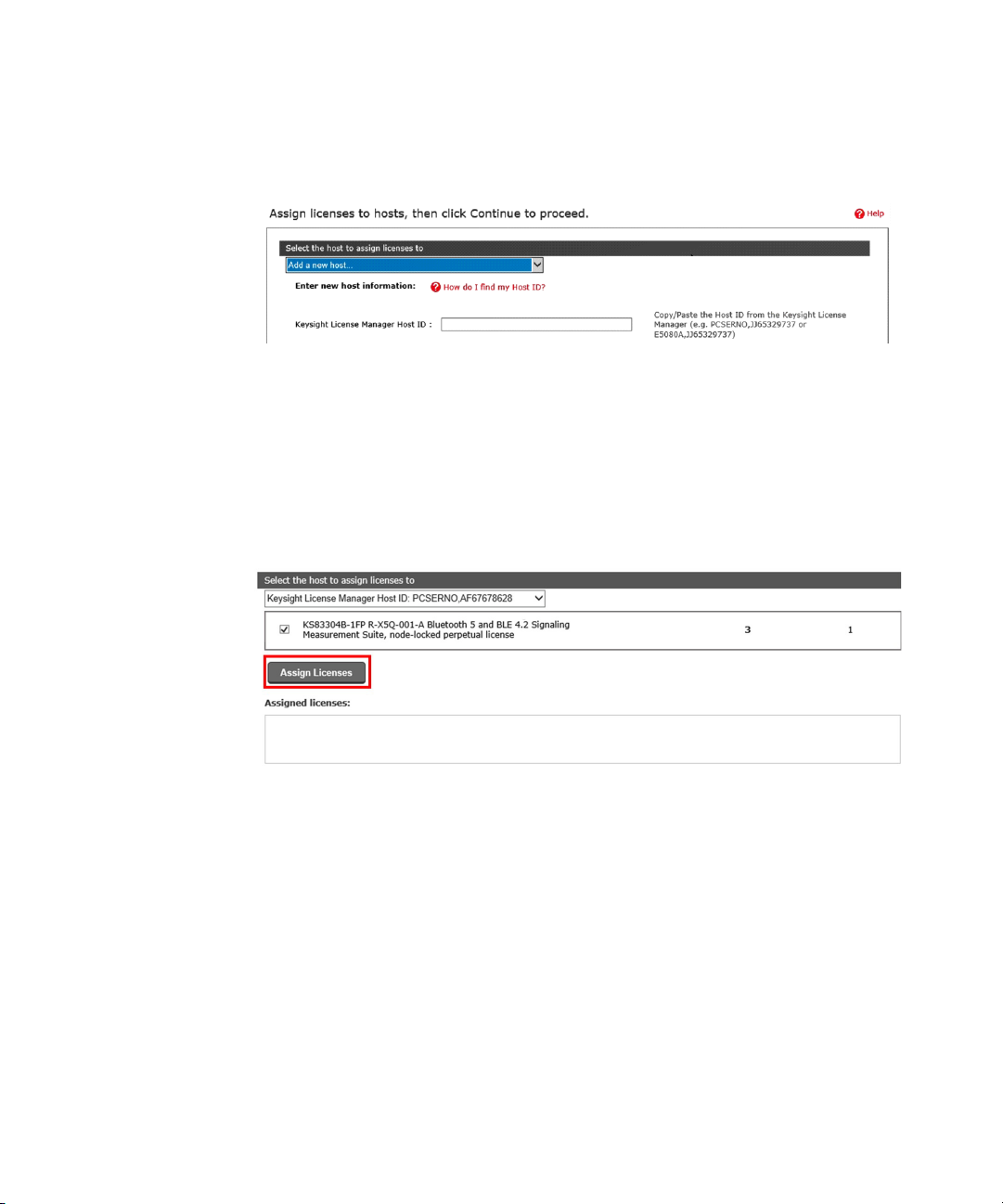
7 Select a host to assign your licenses. Depending on the type of license(s)
selected, you are required to provide any one of the following information.
a For node-locked licenses, click ‘Add a new Keysight License Manager
Host ID host’ and enter the Host ID.
b For floating licenses, click ‘Add a new MAC Address host’ and enter the
MAC address of your server.
c For USB portable licenses, click ‘Add a new USB Portable FlexNet ID host’
and enter the Flexnet ID printed on the USB dongle.
8 Select the license to assign to the specific Host ID and click Assign Licenses.
Verify the details before you click Continue.
20 Keysight ZA0060A Quick Start Guide
Page 21
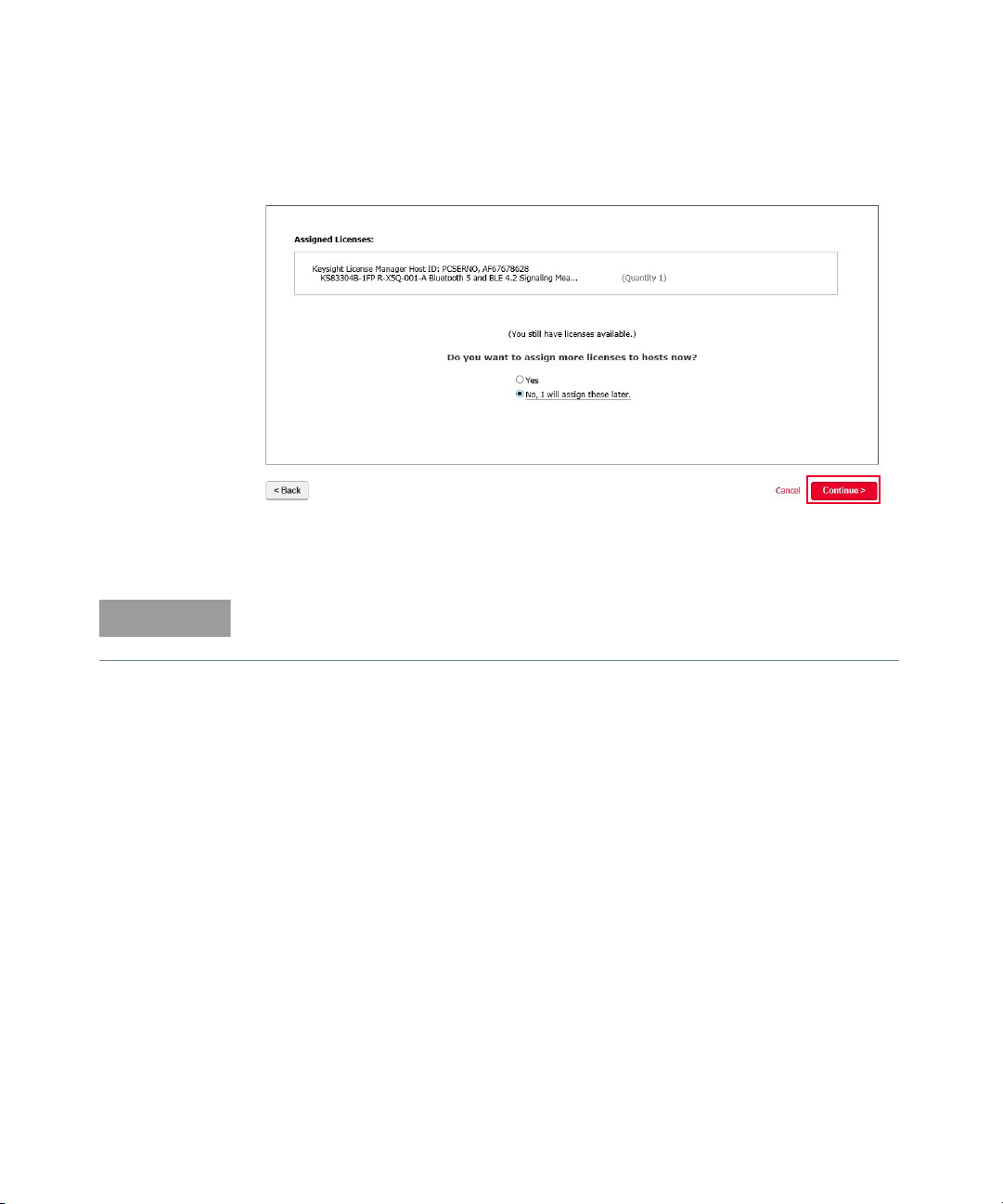
9 You should see the page below. Click Yes to assign more license(s) to other
NOTE
hosts. Otherwise, click No and followed by Continue.
10 Enter your email address and click Submit. You should receive an email
shortly.
For more information, view the Keysight Software Manager Help File.
Keysight ZA0060A Quick Start Guide 21
Page 22
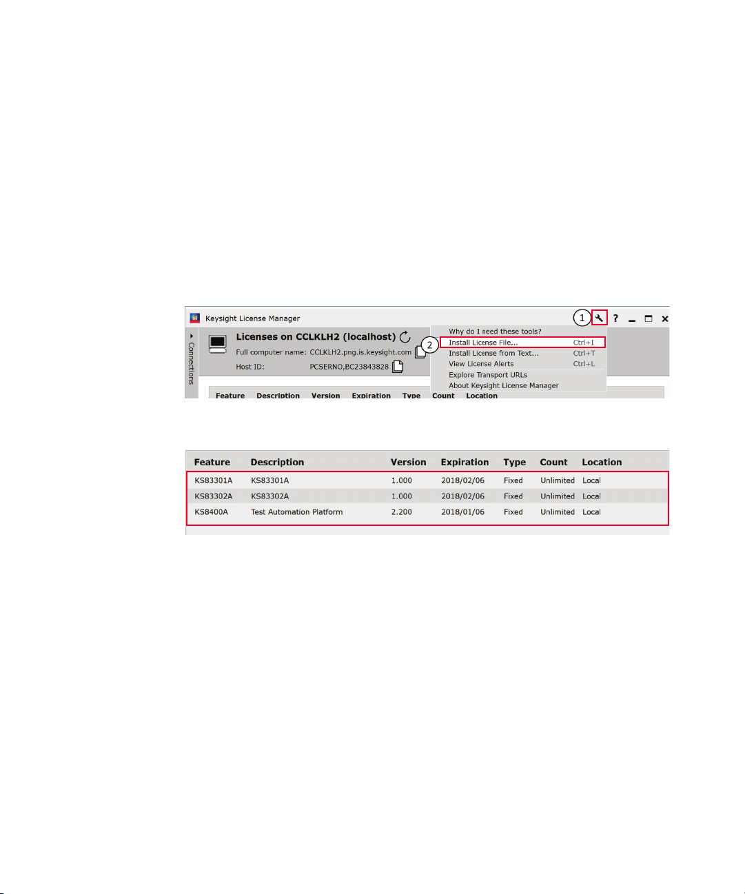
TAP and Measurement Suite License Installation
Node-Locked License
1 You will receive an email for the license file(s). Copy the attachment with the
.lic extension to your PC.
2 Launch Keysight License Manager.
3 Perform the following steps with reference to the image below.
a Click the tools icon (1) followed by Install License File (2).
b Locate the local copy of the License file (.lic) and click Open.
c Successful license installation will be listed as below.
4 Repeat steps 1 through 3 to install more than one licenses.
22 Keysight ZA0060A Quick Start Guide
Page 23
USB Portable License
1 You will receive an email for the license file(s). Copy the attachment with the
.lic extension to your PC.
2 Download and install Keysight License Manager 6 at www.keysight.com/find/
KLM6. Double-click the installer and follow the instructions to complete
installation.
3 Download and install the FLEXID10 USB Dongle Driver package at
www.keysight.com/find/licensingusbdriver.
a Extract the files to a convenient location.
b Execute the Setup64.exe (on 64-bit Windows) or Setup32.exe (on 32-bit
Windows). Follow the instructions, accepting the default values.
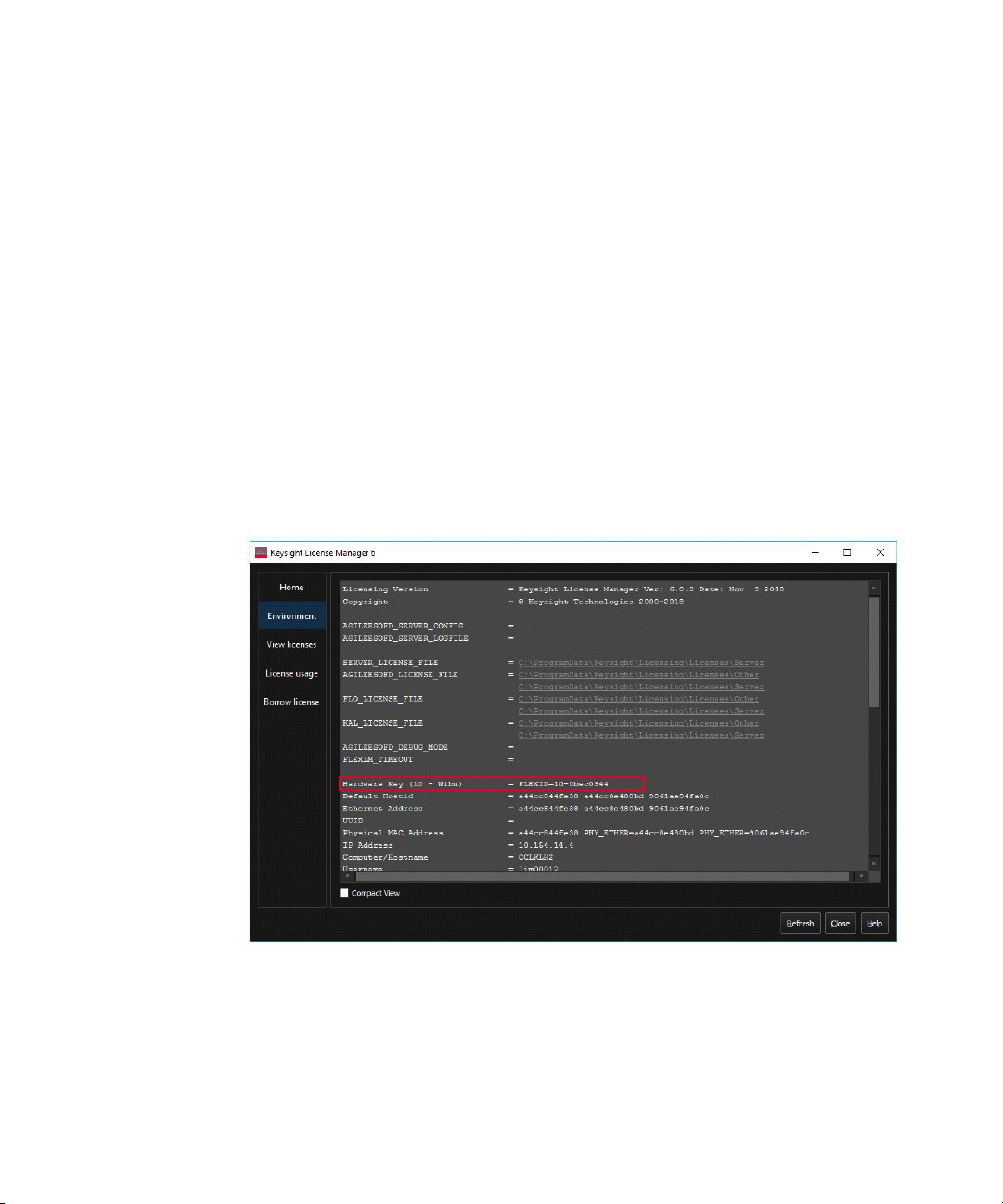
4 Connect the dongle to a USB port. The Flexnet ID is printed on the USB
dongle. With the USB dongle connected to your PC, you can also retrieve the
FlexNet ID in the Environment tab of KLM 6 as shown below.
Keysight ZA0060A Quick Start Guide 23
Page 24
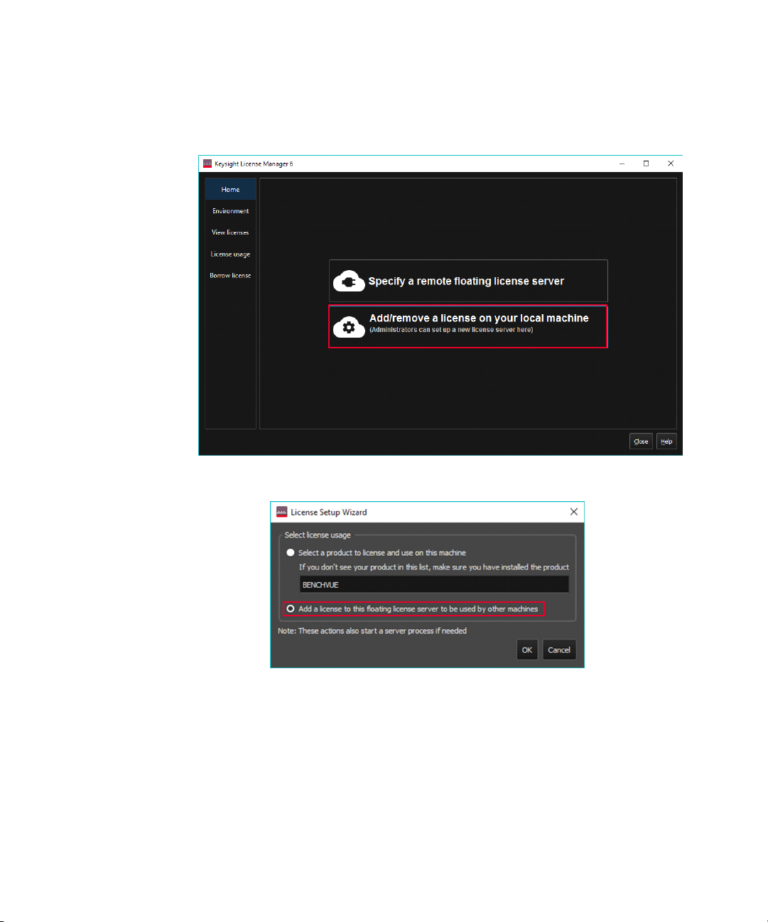
5 Launch Keysight License Manager 6 from your computer’s Start menu. Click
the Add/remove a license to your local machine.
6 Click the Add a license to this floating l icense server to be used by other
machines option.
24 Keysight ZA0060A Quick Start Guide
Page 25
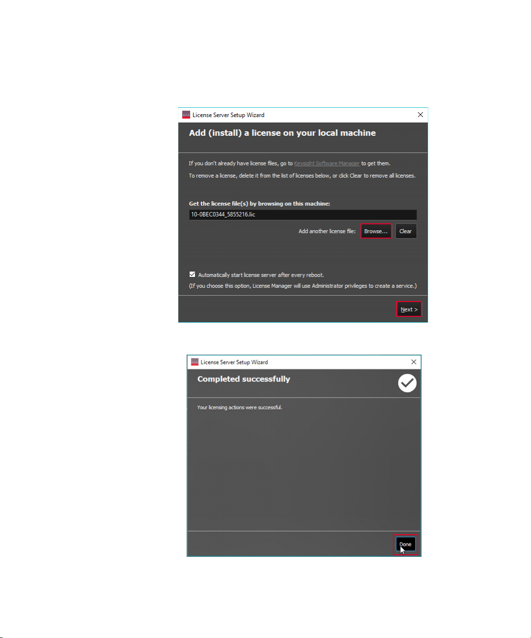
7 Click Browse and browse to the location of the license File. Click Next. When
you are prompted to run a service in a pop-up window, click Yes.
8 You should see the image below the licensing actions were completed
successfully. Click Done.
Keysight ZA0060A Quick Start Guide 25
Page 26
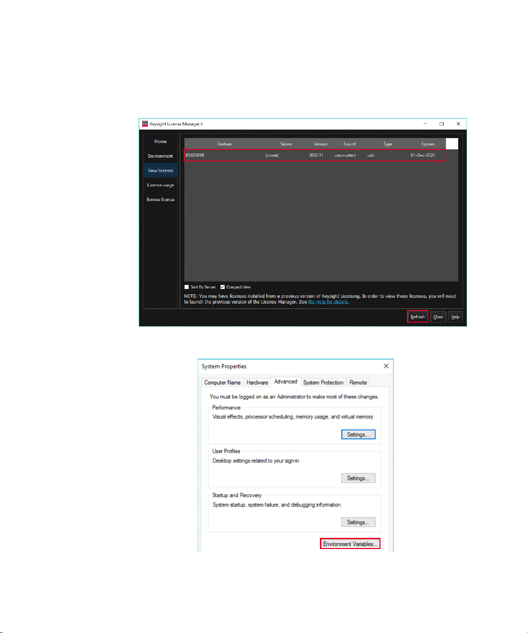
9 Select the View Licenses tab to view the license and the details of the license.
You may need to click Refresh if it is not listed. In this example, KS83301B is
successfully installed in the KLM 6.
10 Go to the Windows menu, search for 'Edit the system environment variables'
and press Enter to view the window below. Click Environment variables.
26 Keysight ZA0060A Quick Start Guide
Page 27
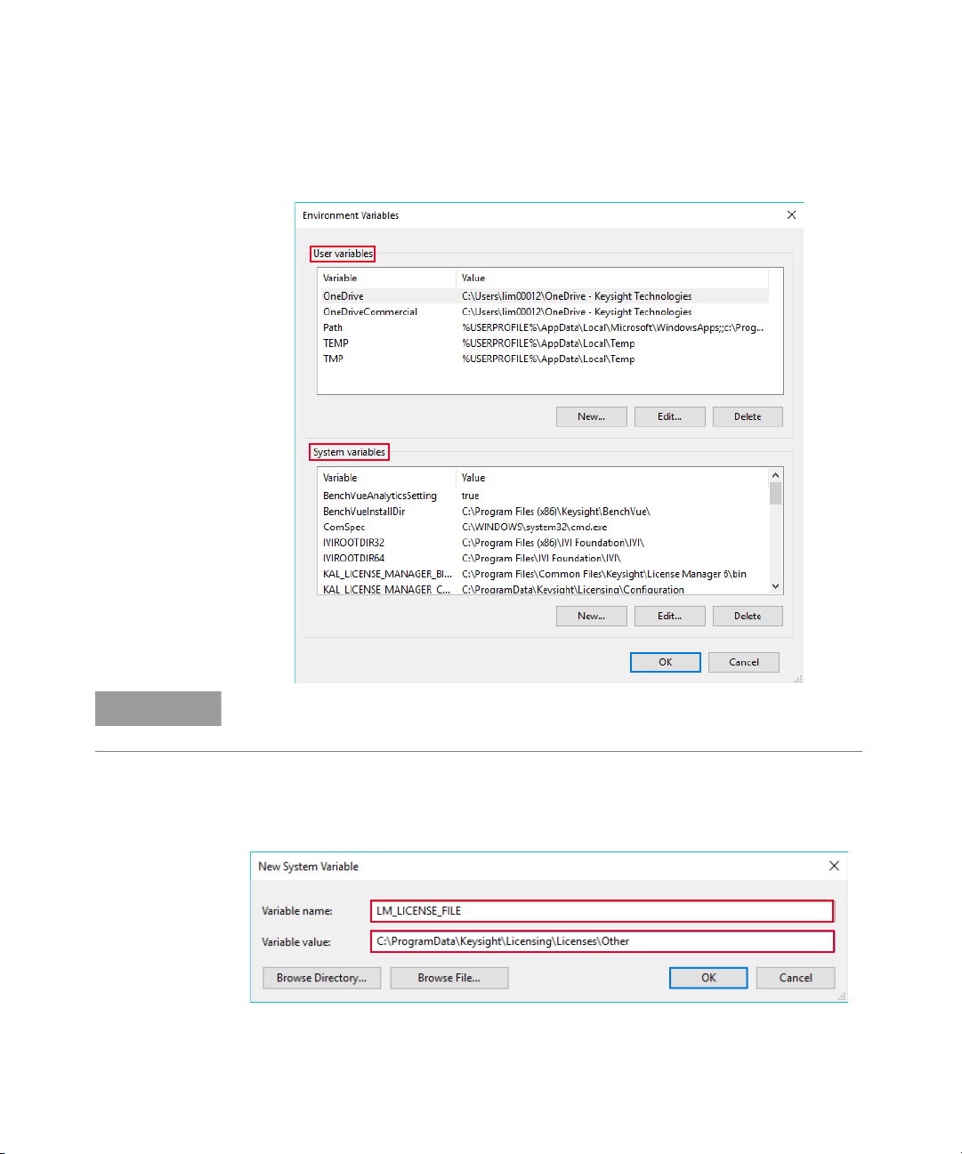
11 Search for the LM_LICENSE_FILE in the User and System variables. You will
NOTE
need to create one if it is not listed in either User or System variables.
Ensure that only one of LM_LICENSE_FILE variable is created in either User or
System variables.
12 Click New to create the LM_LICENSE_FILE variable and enter the information
as shown below. Click OK and you may close all the windows related to
environmental variables.
Keysight ZA0060A Quick Start Guide 27
Page 28
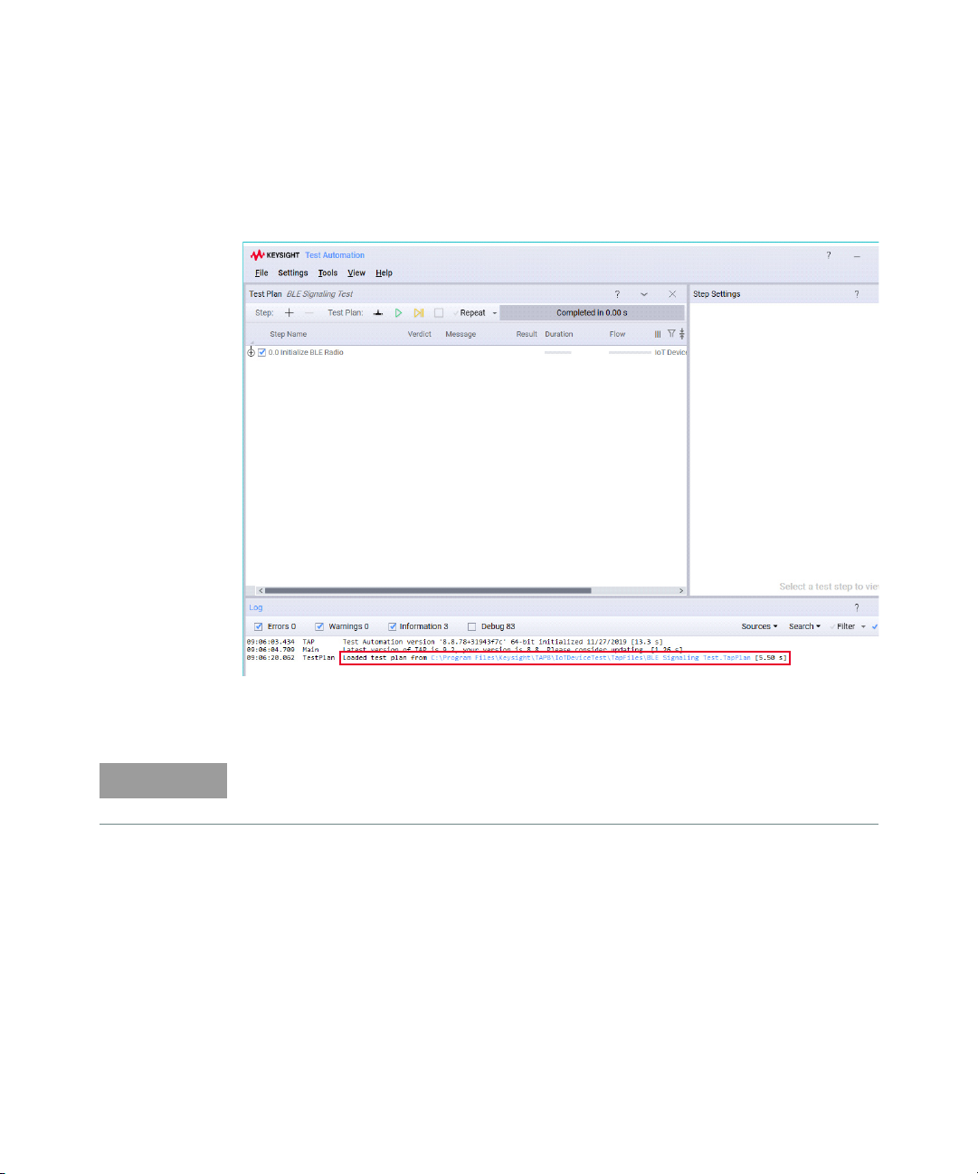
13 Launch TAP and verify if you can load any of the test plans from the installed
NOTE
measurement suite. Based on the example below, you can now load the test
plans from the BLE measurement suite in TAP with the KS83301B license
installed.
14 Repeat these steps on each machine on which you plan to use the USB
portable license.
View the Keysight Licensing Administrator’s Guide for more information.
28 Keysight ZA0060A Quick Start Guide
Page 29
Getting Started: IoT Device Test Add-Ons Package
NOTE
This package consists of the two test steps shown below. The USB coaxial switch
(U1810B and U1816A) and the 34901A module are also required.
a USB Coaxial Switch
Placing this test step in your test plan will allow 34999B RF module to
switch between the RF ports of the USB coaxial switch (supported models
are U1810B and U1816C, subject to the ports available).
b 34901A Measurement
This step requires the use of 34901A module in slot 100 or 300 of the
34972A chassis to measure temperature, DC voltage, and resistance
In the following examples, additional license(s) are required to access the Zigbee
®
and Bluetooth
purchase your license.
Procedure to use USB Coaxial Switch Step (Method 1)
In this example, you will create a test plan to run the Bluetooth® 5 Signaling test
plans on two devices under test (DUT).
1 Launch Keysight TAP. You may turn on the 34972A and allow 15 seconds for
your PC to detect the connection via Keysight Connection Expert.
2 Ensure that you have selected and installed the IoT Device Test Add-Ons
package using the Install wizard shown in Step 5. Otherwise, go to
C:\Program Files\Keysight\TAP8\IoTDeviceTest\TapFiles and double-click IoT
Device Test Add-Ons <version number> TapPackage to install the plug-in.
5 test plans. Contact your local Keysight representative to
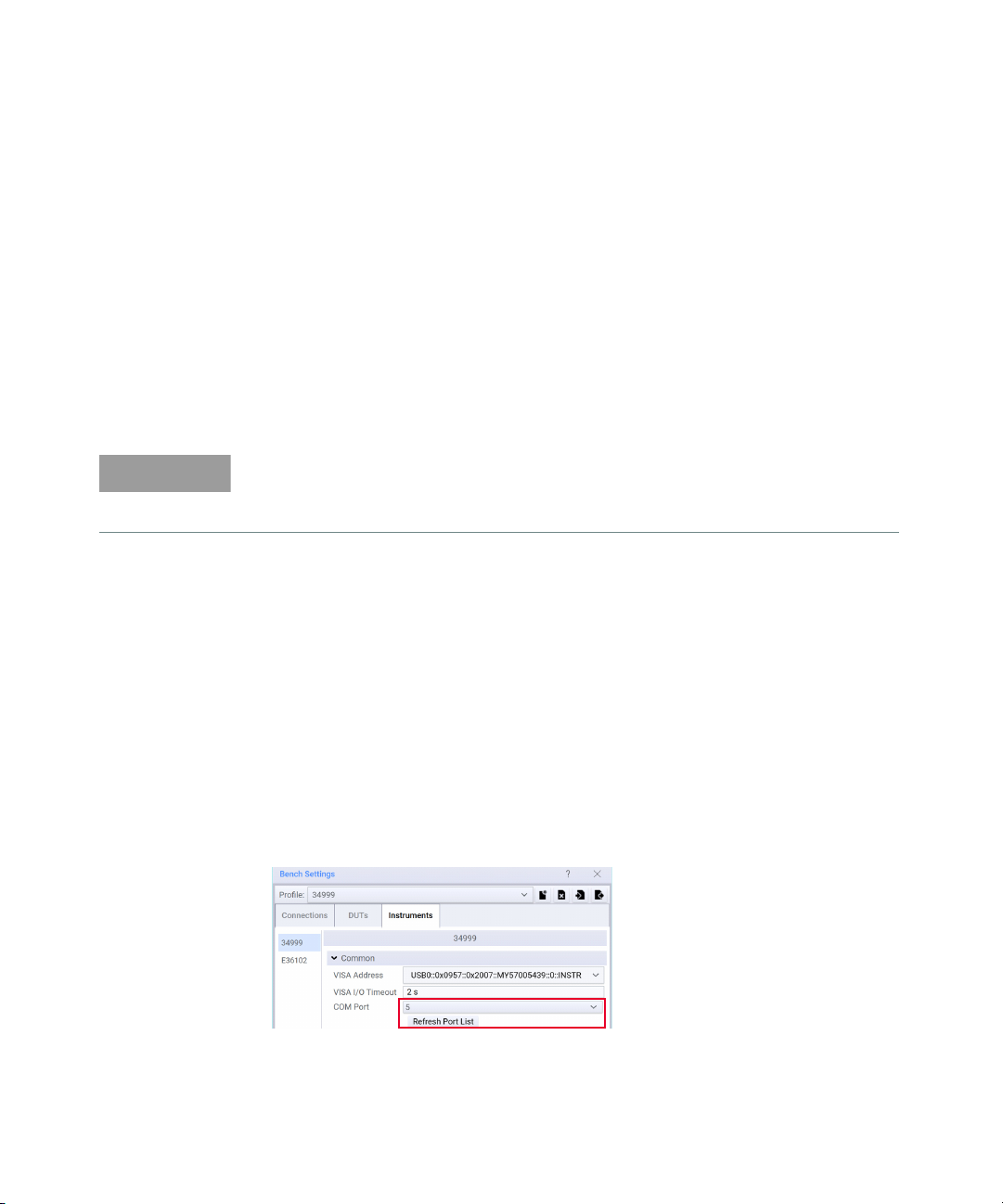
3 Go to Settings > Bench > Instruments to verify the COM Port number selected
in the 34999 profile. Click Refresh Port List to update, if necessary.
Keysight ZA0060A Quick Start Guide 29
Page 30
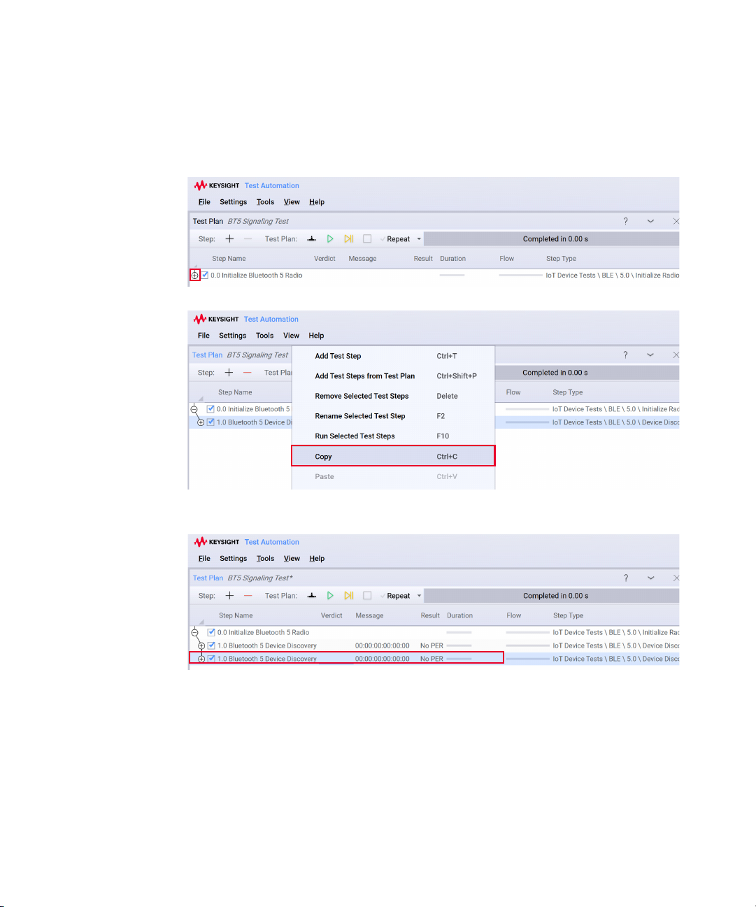
4 Click File > Open and load the Bluetooth
®
5 Signaling test plan.
5 Click the icon highlighted below to expand the 0.0 Initial ize Bluetooth 5
Radio step.
6 Right-click the 1.0 Bluetooth 5 Device Discovery test step and click Copy.
7 Right-click the 1.0 Bluetooth 5 Device Discovery and click Paste to place the
second Bluetooth
®
5 Signaling test plan.
30 Keysight ZA0060A Quick Start Guide
Page 31
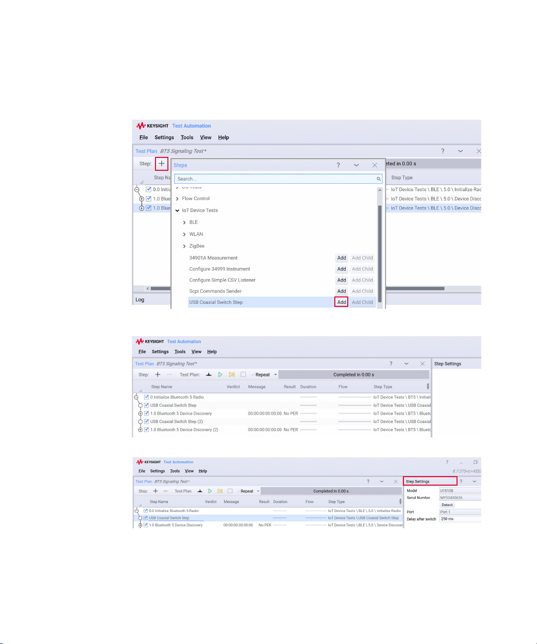
8 Next, add the USB Coaxial Switch Step in your test plan to enable the switch
between Port 1 and 2 of U1810B switch. Click + and click Add for USB Coaxial
Switch Step, twice.
9 Click and drag test steps to rearrange the steps as shown below.
10 Next, configure the Step Settings for the two USB Coaxial Switch Steps.
a Select U1810B or U1816A model from the drop-down list.
Keysight ZA0060A Quick Start Guide 31
Page 32
b Click Detect to update the serial number of the switch. You can find the
NOTE
Test Plan 1
Test Plan 2
matching serial number labeled on the hardware.
c Select the port corresponds to the shield boxes.
i U1810B: Select either Port 1 or Port 2.
ii U1816A: Select Switch 1 or 2 Port to switch to the desired panels.
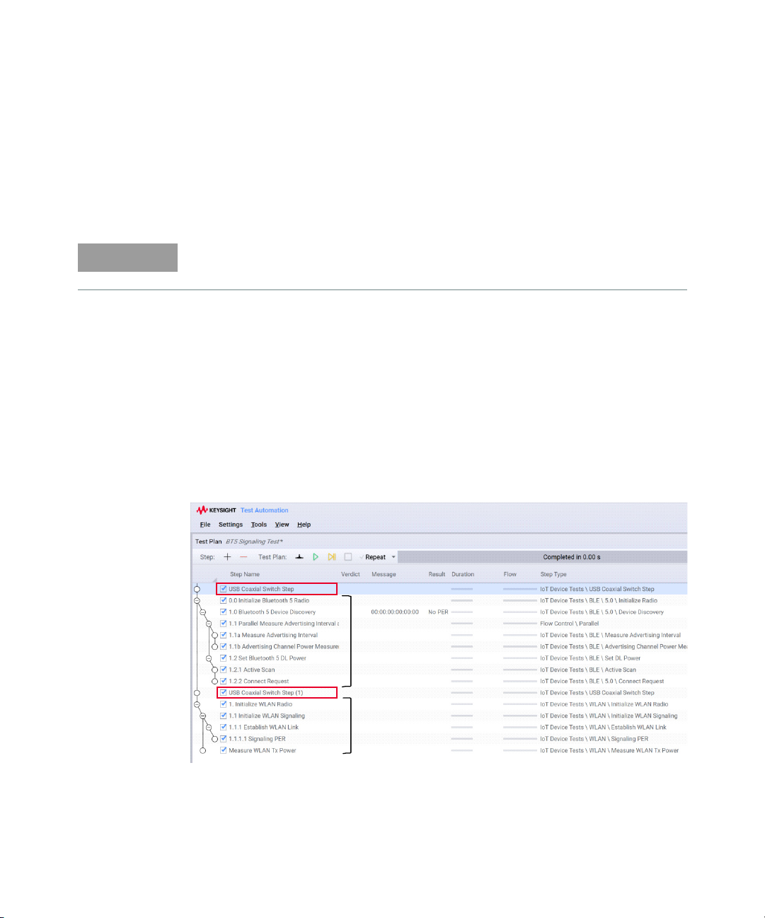
Since there are two of this steps, ensure that one is set to Port 1 and the other as
Port 2 to enable the switching between the DUTs in the shield boxes.
c Delay after switch is set at 250 ms (default) after the RF path has switched
to allow a connection.
This test plan structure will initialize the Bluetooth
®
of the switch and run the Bluetooth
5 Signaling test plan on the first DUT. When
®
radio and then turn on Port 1
that test plan finished, it will switch to Port 2 and test the second DUT.
For this example, you only initialize the Bluetooth
Bluetooth
®
Signaling test plans on two DUTs. If you intend to run two test plans
®
radio once to run the
that uses different radios, place the USB Coaxial Switch Step at the start of the
first and second test plan as shown below.
32 Keysight ZA0060A Quick Start Guide
Page 33
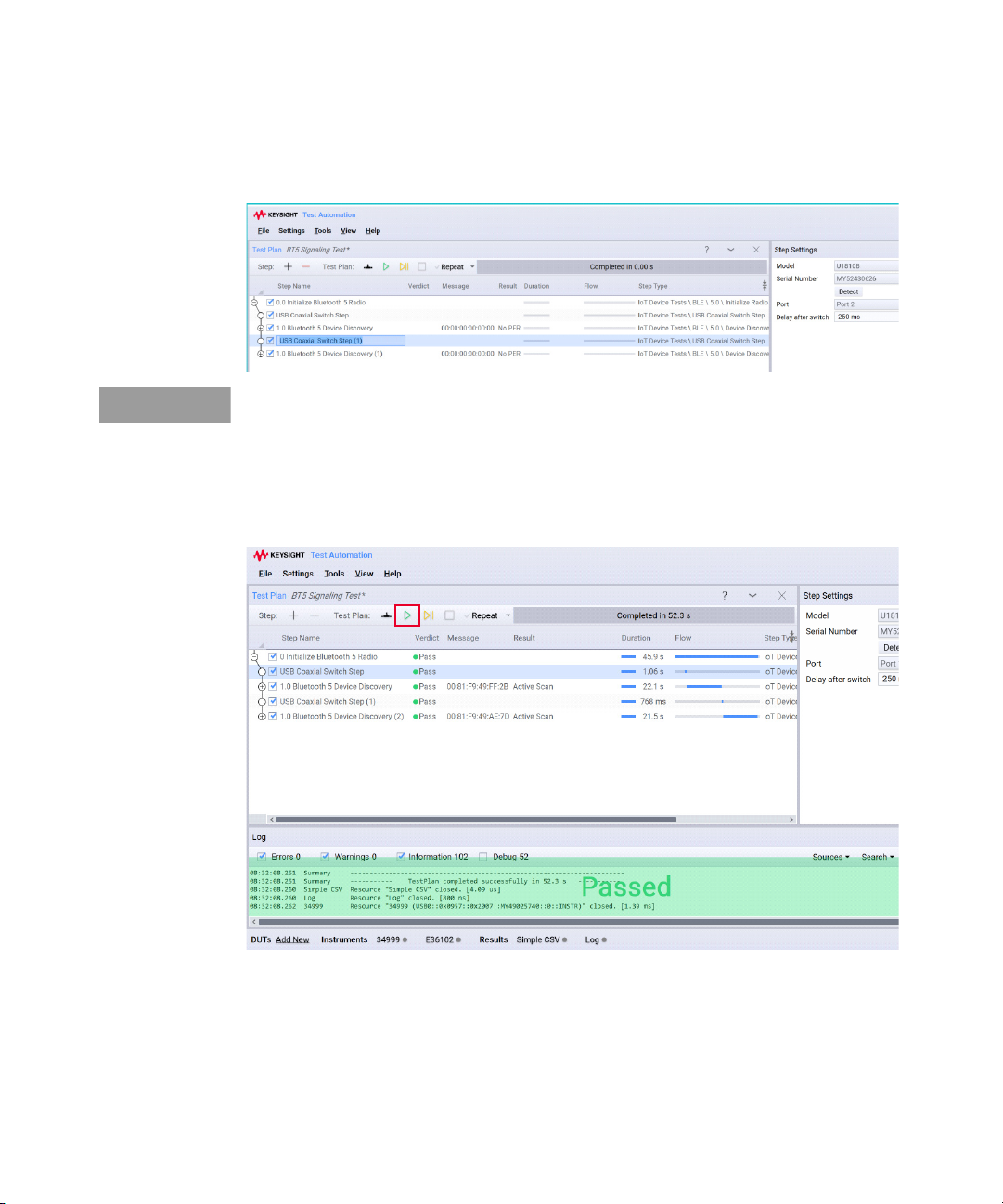
11 Double-click a test step to rename it according to the USB switch or ports
NOTE
selected.
For those who wish to record and export their data, go to Record and export data
to set up the Results Listener plug-ins before you run the test plan.
12 Your test plan is complete and ready to run. Turn on your DUTs and place
them in the shield boxes. Click Run to start your test plan. An example of a
successful run is shown below.
13 Once the test is complete, you can view the results at the ‘Step Settings’ tab
for each test step. For those who have set up the Results Listener plug-ins,
find your recorded results in the default directory C:\Program
Files\Keysight\Tap8\Results to open each file in Microsoft Excel.
Keysight ZA0060A Quick Start Guide 33
Page 34
Procedure to use USB Coaxial Switch Step (Method 2)
NOTE
This is an alternative method to loop the Bluetooth® 5 Signaling test plan.
1 Follow step 1 to 5 of the above method.
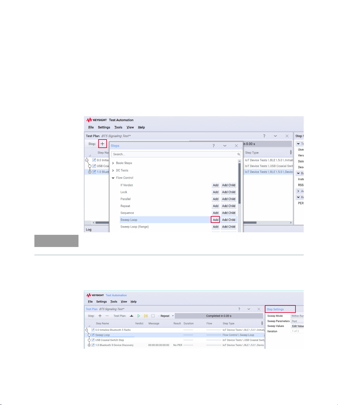
2 Click + and Add for the Sweep Loop and USB Coaxial Switch Step. You can
also add a Delay step of 500 milliseconds as recommended to allow the
U1810B switch to make a connection.
The settings for USB Coaxial Switch Step are as described in Step 10.
3 Drag the Sweep Loop test step and place it after 0 Initialize Bluetooth 5
Radio. Ensure the USB Coaxial Switch and the remaining test steps are placed
as the child steps of Sweep Loop.
34 Keysight ZA0060A Quick Start Guide
Page 35
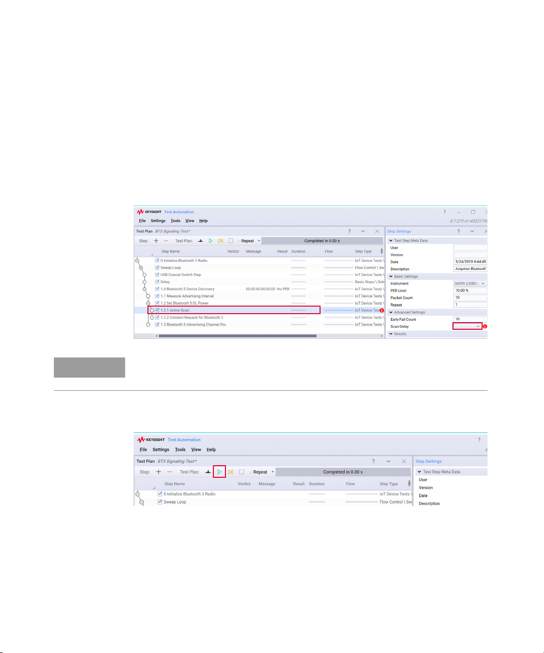
4 Modify the Step Settings to the following:
NOTE
a Sweep Mode: Within Run
b Sweep Parameters: Port
c Sweep Values: Click Edit Values and select Port 1 and Port 2
d Iteration: 1 of 2
5 Before you run the test plan, expand the remaining test steps and take note of
other dependencies as marked by the red icon. In the example below, you
need to manually select the Scan Delay setting for the Active Scan test step.
For those who wish to record and export their data, go to Record and export data
to set up the Results Listener plug-ins before you run the test plan.
6 The structure of your test plan should be similar as above. Turn on your DUTs
and place them in the shield boxes before you run the test. Click Run.
7 Once the test is complete, you can view the results at the ‘Step Settings’ tab
for each test step. For those who have set up the Results Listener plug-ins,
find your recorded results in the default directory C:\Program
Files\Keysight\Tap8\Results to open each file in Microsoft Excel.
Keysight ZA0060A Quick Start Guide 35
Page 36
Procedure to use 34901 Measurement
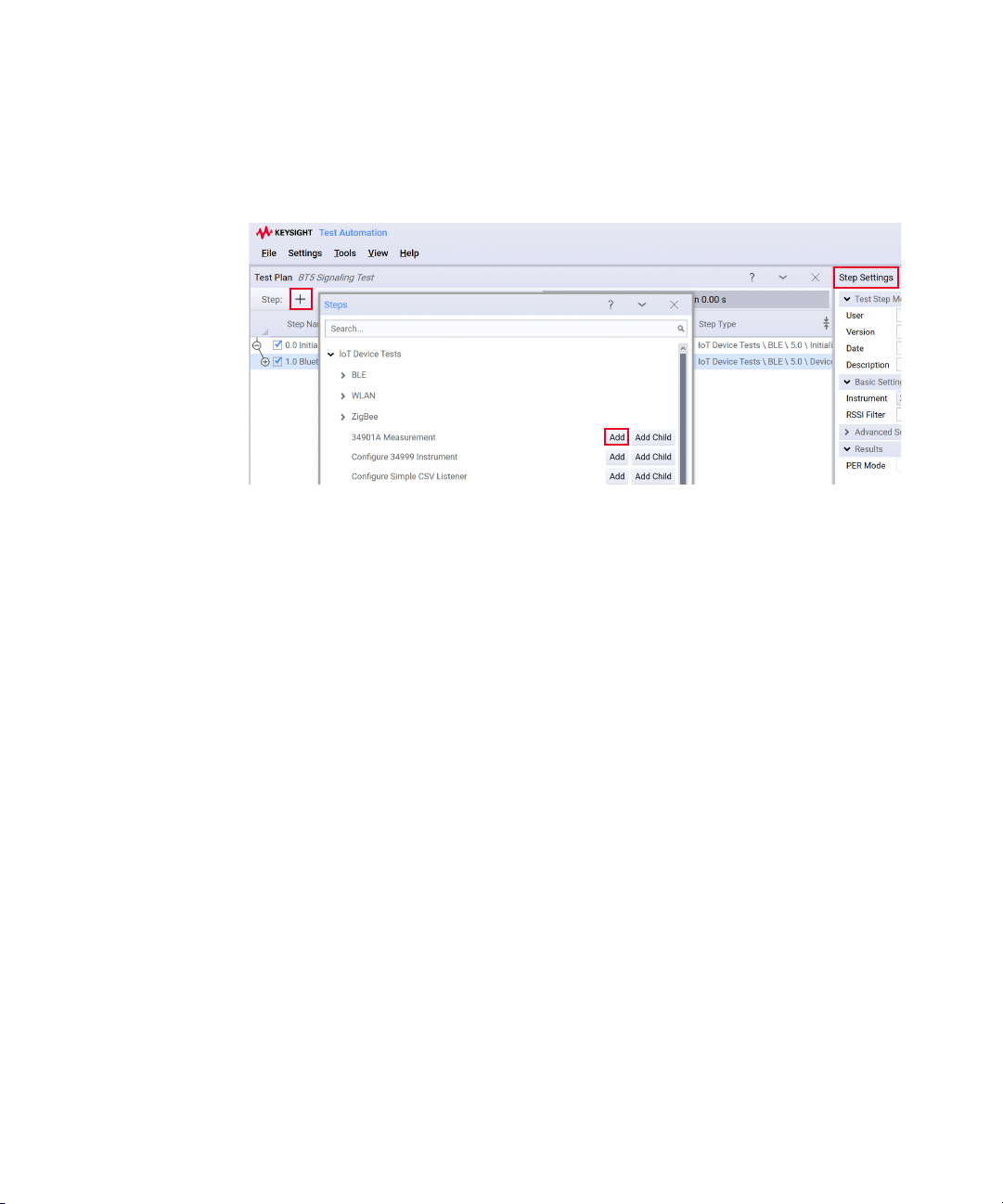
1 Click + and click Add to place a 34901 Measurement step in your test plan.
2 On the Steps Settings panel (towards the right), configure these settings:
a Basic Settings
– Instrument: Select the VISA address of your 34972A
– Slot: Select 1 or 3 to indicate the slot number of 34901A module in the
34972A (as 34999B is in slot 2)
– Measurement: Supported measurements are Temperature, DC voltage,
2-wire resistance, and 4-wire resistance
– Channels: Hover your cursor on the squares to select channel 1 to 20. For
4-wire resistance measurement, the channels range from 1 to 10.
Note: Default parameters are shown in bold.
3 Based on your choice of measurement, configure the respective settings:
a Temperature Measurement Settings
– Probe Type: Thermistor, Thermocouple, 2-wire RTD, and 4-wire RTD
– Type:
– Thermocouple: B, E, J, K, N, R, S, T
– Thermistor: 2252, 5000, 10000
– 2-wire and 4-wire RTD: 85, 91
– Resolution: Default, Maximum, Minimum, and Custom. For custom resolution,
enter the resolution value in °C in the entry box.
36 Keysight ZA0060A Quick Start Guide
Page 37
b DC Voltage Measurement Settings
NOTE
– Range: Auto, 100 mV, 1 V, 10 V, 100 V, and 300 V.
– Resolution: Default, Maximum, Minimum, and Custom. For custom resolution,
enter the resolution value in V in the entry box.
c Resistance Measurement Settings (2-wire Resistance and 4-wire
Resistance)
– Range: Auto, 100 Ω, 1 kΩ, 10 kΩ, 100 kΩ, 1 MΩ, 10 MΩ, and 100 MΩ.
– Resolution: Default, Maximum, Minimum, and Custom. For custom resolution,
enter the resolution value in Ω in the entry box.
For those who wish to record and export their data, go to Record and export data
to set up the Results Listener plug-ins before you run the test plan.
4 Turn on your DUT and place them in the shield box before you run the test
plan. Click Run to start your test plan.
5 Once the test is complete, you can view the results at the ‘Step Settings’ tab
for each test step. For those who have set up the Results Listener plug-ins,
find your recorded results in the default directory C:\Program
Files\Keysight\Tap8\Results to open each file in Microsoft Excel.
For your information, these are the commands used to perform measurements in
the 34901A Measurement test step.
a MEASure:TEMPerature?
{TCouple|RTD|FRTD|THERmistor},{<type>},1,{<resolution>|MIN
|MAX|DEF}, (@<scan_list>)
b MEASure:VOLT:DC?
{<range>|AUTO},{<resolution>|MIN|MAX|DEF}, (@<scan_list>)
c MEASure:RESitance?
{<range>|AUTO},{<resolution>|MIN|MAX|DEF}, (@<scan_list>)
d MEASure:FRESitance?
{<range>|AUTO},{<resolution>|MIN|MAX|DEF}, (@<scan_list>)
Refer to 34901A Quick Reference Guide or 34970A User’s Guide.
Keysight ZA0060A Quick Start Guide 37
Page 38
Record and export data
Other than viewing the results in the ‘Step Settings’ tab or the Log panel, you may
configure the TAP software using the Result Listener plug-ins. The TAP software
includes Result Listener plug-ins for the purpose of storing results such as Text
Log and CSV files.
– Text Log File allows you to save the text log separately after each run, and
its file names support macros.
– CSV file will save collected data in data analysis software.
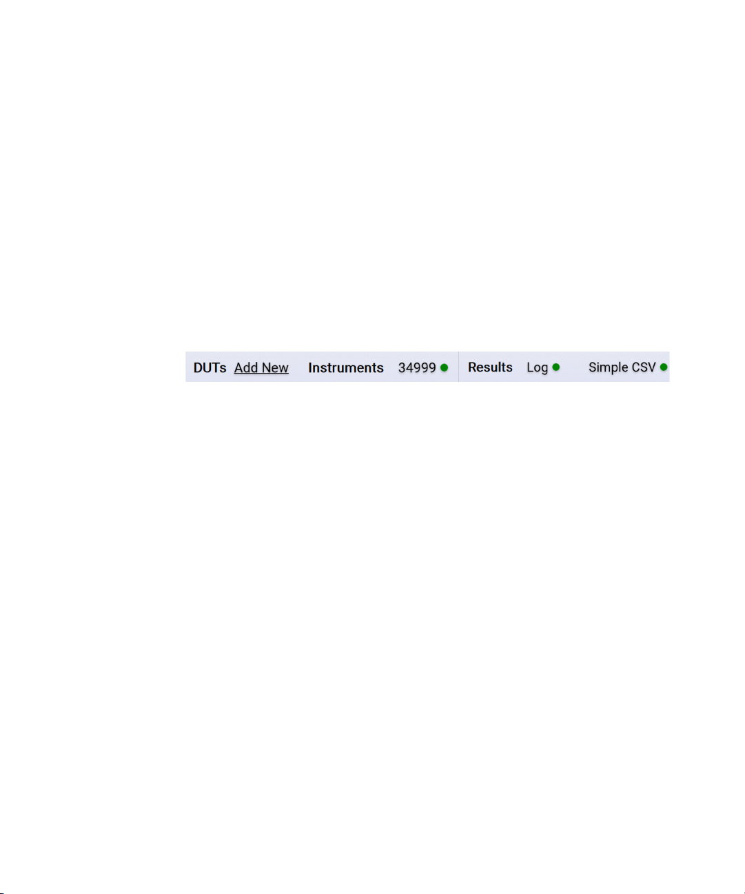
The default listener is Simple CSV Listener, which will appear next to the Results
section at Resource bar shown below.
If not already configured, follow the instructions below to configure the plug-ins.
1 Click Simple CSV listed at the bottom of the Log panel.
2 Select the check boxes corresponding to the desired Result Listener plug-ins
on the left tab. Click + to view more options other than Log and Simple CSV.
A simple CSV Result Listener will generate report into specific folders:
– Saving ResultSaveMode is set to Single Report, the report is saved as:
[<CustomPrefix>_]YYYYMMDD_HHmmss_<TestPlan>_<Verdict>.csv
– Saving ResultSaveMode is set to Individual Reports, the reports are saved
as one CSV file per report name into a folder with the name
[<CustomPrefix>_]YYYYMMDD_HHmmss_<TestPlan>_<Verdict>.
3 For Log, configure the File Path settings and set the Filter Options according
to your preference.
4 Click OK to return to your test plan.
5 When your test plan completes, find your recorded results in the default
directory C:\Program Files\Keysight\Tap8\Results to open each file in
Microsoft Excel.
38 Keysight ZA0060A Quick Start Guide
Page 39
Troubleshooting and Error Messages
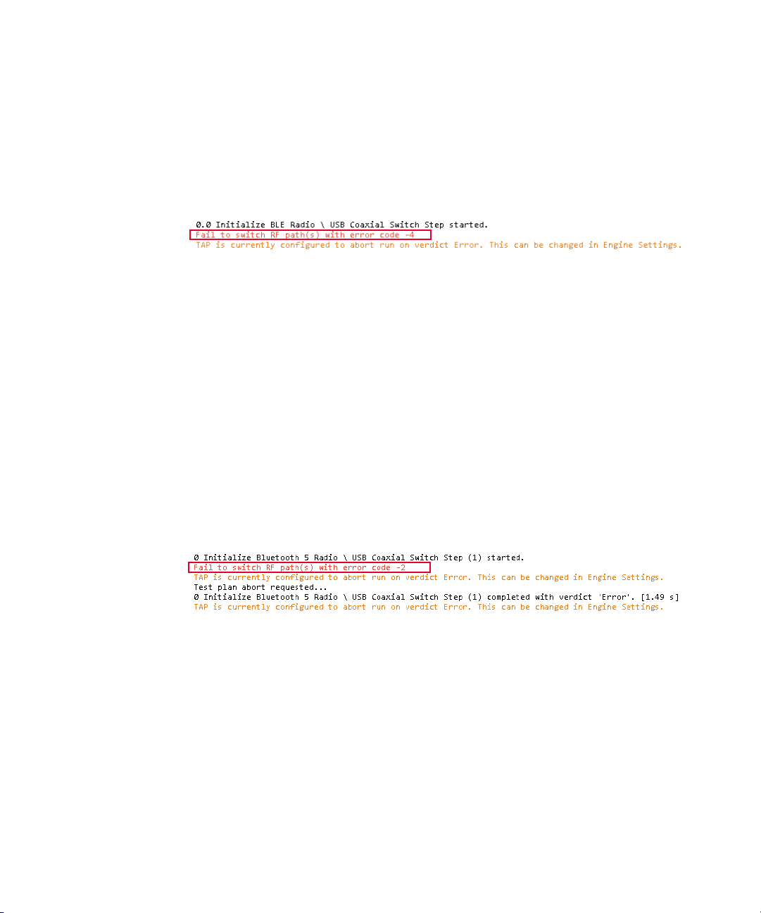
Fail to switch RF path(s) with error code -4
The error message below could be caused by the following issues:
– Incorrect serial number of the USB coaxial switch
–Faulty USB cable
– USB coaxial switch not plugged in
Here are the few tips you can try (applicable for U1810B and U1816A).
– Ensure that the serial number of the USB coaxial switch matches that in Step
Settings.
– Check the connection of the USB cable to your PC and the switch is secure.
– Verify the green LED beside the USB port on the USB coaxial switch. It will
light up when the switch is connected to the PC.
– Replace the faulty cable with a new one.
Fail to switch RF path(s) with error code -2
You will see this error message when there is no power to the USB coaxial switch.
Here are the few tips you can try.
– Check the connection of the USB cable to your PC and the switch is secure.
– When the USB coaxial switch is plugged in, you should see the green LED light
up.
– Ensure that the power supply is functioning well.
– Replace the faulty cable with a new one.
Keysight ZA0060A Quick Start Guide 39
Page 40
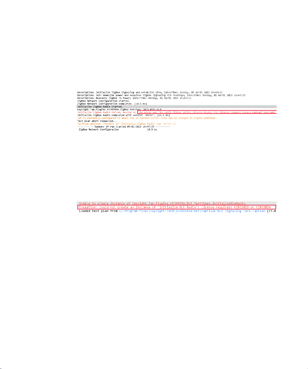
No valid BLE/WLAN/Zigbee option license found. For license request please contact Keysight Technologies Sales & Support.
Depending on the options purchased, this error message indicates that the
respective radio options are not enabled on your 34999B boards. You will need to
purchase the license(s) to use by contacting your local Keysight representative.
Once you have purchased your license(s), refer to the instructions in the
entitlement certificate to redeem your license(s).
Could not create '<Test step>': License required: KS8330xA or KS8330xB
An example of the error message shown above indicates that there is no
KS83301A or KS83301B license installed. You will need to purchase the following
licenses before being able to access and create the test steps.
Here are the few tips you can try.
– Purchase the following license(s) according to your test requirement by
contacting your local Keysight representative.
– KS83304B for Bluetooth
– KS83305B for Zigbee 3.0 and Zigbee Pro related test plans
– Follow the instructions in the entitlement certificate on how to redeem the
license.
40 Keysight ZA0060A Quick Start Guide
®
5 related test plans
Page 41

THIS PAGE HAS BEEN INTENTIONALLY LEFT BLANK.
Keysight ZA0060A Quick Start Guide 41
Page 42
This information is subject to change
without notice. Always refer to the
English version at the Keysight website
for the latest revision.
© Keysight Technologies 2019
Edition 1, December 2019
Printed in Malaysia
*ZA0060-90001*
ZA0060-90001
www.keysight.com
 Loading...