

Page 1

Keysight U8480 Series USB
Thermocouple Power Sensor
Programming
Guide
Page 2

Notices
CAUTION
WARNING
Copyright Notice
© Keysight Technologies 2012–2019
No part of this manual may be
reproduced in any form or by any
means (including electronic storage
and retrieval or translation into a
foreign language) without prior
agreement and written consent from
Keysight Technologies as governed by
United States and international
copyright laws.
Manual Part Number
U8481-90003
Edition
Edition 9, April 15, 2019
Printed in:
Printed in Malaysia
Published by:
Keysight Technologies
Bayan Lepas Free Industrial Zone,
11900 Penang, Malaysia
Technology Licenses
The hard ware and/or software
described in this document are
furnished under a license and may be
used or copied only in accordance with
the terms of such license.
Declaration of Conformity
Declarations of Conformity for this
product and for other Keysight
products may be downloaded from the
Web. Go to http://www.keysight.com/
go/conformity. You can then search by
product number to find the latest
Declaration of Conformity.
U.S. Government Rights
The Software is “commercial computer
software,” as defined by Federal
Acquisition Regulation (“FAR”) 2.101.
Pursuant to FAR 12.212 and 27.405-3
and Department of Defense FAR
Supplement (“DFARS”) 227.7202, the
U.S. government acquires commercial
computer software under the same
terms by which the software is
customarily provided to the public.
Accordingly, Keysight provides the
Software to U.S. government
customers under its standard
commercial license, which is embodied
in its End User License Agreement
(EULA), a copy of which can be found
at http://www.keysight.com/find/
sweula. The license set forth in the
EULA represents the exclusive authority
by which the U.S. government may use,
modify, distribute, or disclose the
Software. The EULA and the license set
forth therein, does not require or
permit, among other things, that
Keysight: (1) Furnish technical
information related to commercial
computer software or commercial
computer software documentation that
is not customarily provided to the
public; or (2) Relinquish to, or
otherwise provide, the government
rights in excess of these rights
customarily provided to the public to
use, modify, reproduce, release,
perform, display, or disclose
commercial computer software or
commercial computer software
documentation. No additional
government requirements beyond
those set forth in the EULA shall apply,
except to the extent that those terms,
rights, or licenses are explicitly required
from all providers of commercial
computer software pursuant to the FAR
and the DFARS and are set forth
specifically in writing elsewhere in the
EULA. Keysight shall be under no
obligation to update, revise or
otherwise modify the Software. With
respect to any technical data as
defined by FAR 2.101, pursuant to FAR
12.211 and 27.404.2 and DFARS
227.7102, the U.S. government
acquires no greater than Limited Rights
as defined in FAR 27.401 or DFAR
227.7103-5 (c), as applicable in any
technical data.
Warranty
THE MATERIAL CONTAINED IN THIS
DOCUMENT IS PROVIDED “AS IS,” AND
IS SUBJECT TO BEING CHANGED,
WITHOUT NOTICE, IN FUTURE
EDITIONS. FURTHER, TO THE MAXIMUM
EXTENT PERMITTED BY APPLICABLE
LAW, KEYSIGHT DISCLAIMS ALL
WARRANTIES, EITHER EXPRESS OR
IMPLIED, WITH REGARD TO THIS
MANUAL AND ANY INFORMATION
CONTAINED HEREIN, INCLUDING BUT
NOT LIMITED TO THE IMPLIED
WARRANTIES OF MERCHANTABILITY
AND FITNESS FOR A PARTICULAR
PURPOSE. KEYSIGHT SHALL NOT BE
LIABLE FOR ERRORS OR FOR
INCIDENTAL OR CONSEQUENTIAL
DAMAGES IN CONNECTION WITH THE
FURNISHING, USE, OR PERFORMANCE
OF THIS DOCUMENT OR OF ANY
INFORMATION CONTAINED HEREIN.
SHOULD KEYSIGHT AND THE USER
HAVE A SEPARATE WRITTEN
AGREEMENT WITH WARRANTY TERMS
COVERING THE MATERIAL IN THIS
DOCUMENT THAT CONFLICT WITH
THESE TERMS, THE WARRANTY TERMS
IN THE SEPARATE AGREEMENT SHALL
CONTROL.
Safety Information
A CAUTION notice denotes a hazard. It
calls attention to an operating
procedure, practice, or the like that, if
not correctly performed or adhered to,
could result in damage to the product
or loss of important data. Do not
proceed beyond a CAUTION notice
until the indicated conditions are fully
understood and met.
A WARNING notice denotes a hazard. It
calls attention to an operating
procedure, practice, or the like that, if
not correctly performed or adhered to,
could result in personal injury or death.
Do not proceed beyond a WARNING
notice until the indicated conditions are
fully understood and met.
2 U8480 Series Programming Guide
Page 3

Table of Contents
1 U8480 Series Remote Operation
Introduction . . . . . . . . . . . . . . . . . . . . . . . . . . . . . . . . . . . . . . . . . . . . . .16
Configuring the USB Interface . . . . . . . . . . . . . . . . . . . . . . . . . . . . . . . .17
An Introduction to the SCPI Language . . . . . . . . . . . . . . . . . . . . . . . . . 18
Zeroing and Calibrating the U8480 Series . . . . . . . . . . . . . . . . . . . . . . .26
Making Measurements . . . . . . . . . . . . . . . . . . . . . . . . . . . . . . . . . . . . . .28
Using Frequency-Dependent Offset Tables . . . . . . . . . . . . . . . . . . . . . .36
Setting the Averaging . . . . . . . . . . . . . . . . . . . . . . . . . . . . . . . . . . . . . . .43
Setting Offsets . . . . . . . . . . . . . . . . . . . . . . . . . . . . . . . . . . . . . . . . . . . .45
Setting Measurement Limits . . . . . . . . . . . . . . . . . . . . . . . . . . . . . . . . .46
Getting the Best Speed Performance . . . . . . . . . . . . . . . . . . . . . . . . . . 50
How Measurements are Calculated . . . . . . . . . . . . . . . . . . . . . . . . . . . .53
Status Reporting . . . . . . . . . . . . . . . . . . . . . . . . . . . . . . . . . . . . . . . . . . .54
Saving and Recalling U8480 Series Configurations . . . . . . . . . . . . . . .69
Using Device Clear to Halt Measurements . . . . . . . . . . . . . . . . . . . . . .70
2 MEASurement Commands
Measurement Commands . . . . . . . . . . . . . . . . . . . . . . . . . . . . . . . . . . .72
CONFigure[1]? . . . . . . . . . . . . . . . . . . . . . . . . . . . . . . . . . . . . . . . . . . . .74
CONFigure[1] Command . . . . . . . . . . . . . . . . . . . . . . . . . . . . . . . . . . . .75
CONFigure[1][:SCALar][:POWer:AC]
[<expected_value>[,<resolution>[,<source list>]]] . . . . . . . . . . . . . . .76
FETCh[1]? Query . . . . . . . . . . . . . . . . . . . . . . . . . . . . . . . . . . . . . . . . . . .78
FETCh[1][:SCALar][:POWer:AC]? [<expected_value>[,<resolution>[,<source
list>]]] . . . . . . . . . . . . . . . . . . . . . . . . . . . . . . . . . . . . . . . . . . . . . . . . .79
FETCh[1][:SCALar][:POWer:AC]:MUNC? [<expected_value>[,<resolu-
tion>[,<source list>]]] . . . . . . . . . . . . . . . . . . . . . . . . . . . . . . . . . . . . . 81
READ[1] Query . . . . . . . . . . . . . . . . . . . . . . . . . . . . . . . . . . . . . . . . . . . .83
READ[1][:SCALar][:POWer:AC]? [<expected_value>[,<resolution>[,<source
U8480 Series Programming Guide 3
Page 4

list>]]] . . . . . . . . . . . . . . . . . . . . . . . . . . . . . . . . . . . . . . . . . . . . . . . . . 84
READ[1][:SCALar][:POWer:AC]:MUNC? [<expected_value>[,<resolu-
tion>[,<source list>]]] . . . . . . . . . . . . . . . . . . . . . . . . . . . . . . . . . . . . . 86
MEASure[1] Query . . . . . . . . . . . . . . . . . . . . . . . . . . . . . . . . . . . . . . . . . 88
MEASure[1][:SCALar][:POWer:AC]? [<expected_value>[,<resolu-
tion>[,<source list>]]] . . . . . . . . . . . . . . . . . . . . . . . . . . . . . . . . . . . . . 89
MEASure[1][:SCALar][:POWer:AC]:MUNC? [<expected_value>[,<resolu-
tion>[,<source list>]]] . . . . . . . . . . . . . . . . . . . . . . . . . . . . . . . . . . . . . 91
3 CALCulate Subsystem
CALCulate Command Subsystem . . . . . . . . . . . . . . . . . . . . . . . . . . . . . 94
CALCulate[1]:FEED[1] <“string”> . . . . . . . . . . . . . . . . . . . . . . . . . . . . . 95
CALCulate[1]:LIMit Commands . . . . . . . . . . . . . . . . . . . . . . . . . . . . . . . 97
CALCulate[1]:LIMit:CLEar:AUTO <boolean>|ONCE . . . . . . . . . . . . . . . . 98
CALCulate[1]:LIMit:CLEar[:IMMediate] . . . . . . . . . . . . . . . . . . . . . . . . 100
CALCulate[1]:LIMit:FAIL? . . . . . . . . . . . . . . . . . . . . . . . . . . . . . . . . . . . 101
CALCulate[1]:LIMit:FCOunt? . . . . . . . . . . . . . . . . . . . . . . . . . . . . . . . . 102
CALCulate[1]:LIMit:LOWer[:DATA] <numeric_value> . . . . . . . . . . . . . 104
CALCulate[1]:LIMit:UPPer[:DATA] <numeric_value> . . . . . . . . . . . . . 106
CALCulate[1]:LIMit:STATe <boolean> . . . . . . . . . . . . . . . . . . . . . . . . . 108
CALCulate[1]:MATH Commands . . . . . . . . . . . . . . . . . . . . . . . . . . . . . 110
CALCulate[1]:MATH[:EXPRession] <“string”> . . . . . . . . . . . . . . . . . . . 111
CALCulate[1]:MATH[:EXPRession]:CATalog? . . . . . . . . . . . . . . . . . . . 113
4 CALibration Subsystem
CALibration Command Subsystem . . . . . . . . . . . . . . . . . . . . . . . . . . . 116
CALibration[1][:ALL] . . . . . . . . . . . . . . . . . . . . . . . . . . . . . . . . . . . . . . . 117
CALibration[1][:ALL]? . . . . . . . . . . . . . . . . . . . . . . . . . . . . . . . . . . . . . . 118
CALibration[1]:ZERO:AUTO ONCE . . . . . . . . . . . . . . . . . . . . . . . . . . . . 119
CALibration[1]:AUTO [ONCE|ON|OFF|0|1] . . . . . . . . . . . . . . . . . . . . . . 120
CALibration[1]:AUTO? . . . . . . . . . . . . . . . . . . . . . . . . . . . . . . . . . . . . . 122
CALibration[1]:TYPE EXTernal|INTernal . . . . . . . . . . . . . . . . . . . . . . . . 123
4 U8480 Series Programming Guide
Page 5

5FORMat Subsystem
FORMat Command Subsystem . . . . . . . . . . . . . . . . . . . . . . . . . . . . . .126
FORMat[:READings]:BORDer <character_data> . . . . . . . . . . . . . . . . .127
FORMat[:READings][:DATA] <character_data> . . . . . . . . . . . . . . . . . .129
6 MEMory Subsystem
MEMory Command Subsystem . . . . . . . . . . . . . . . . . . . . . . . . . . . . . .133
MEMory:CATalog Queries . . . . . . . . . . . . . . . . . . . . . . . . . . . . . . . . . . .134
MEMory:CATalog[:ALL]? . . . . . . . . . . . . . . . . . . . . . . . . . . . . . . . . . . .135
Example 1: Syntax . . . . . . . . . . . . . . . . . . . . . . . . . . . . . . . . . . . . . . . .136
MEMory:CATalog:STATe? . . . . . . . . . . . . . . . . . . . . . . . . . . . . . . . . . .137
MEMory:CATalog:TABLe? . . . . . . . . . . . . . . . . . . . . . . . . . . . . . . . . . . . 138
MEMory:CLEar Commands . . . . . . . . . . . . . . . . . . . . . . . . . . . . . . . . .140
MEMory:CLEar[:NAME] <“character_data”> . . . . . . . . . . . . . . . . . . . .141
MEMory:CLEar:TABLe . . . . . . . . . . . . . . . . . . . . . . . . . . . . . . . . . . . . .143
MEMory:FREE Queries . . . . . . . . . . . . . . . . . . . . . . . . . . . . . . . . . . . . .144
MEMory:FREE[:ALL]? . . . . . . . . . . . . . . . . . . . . . . . . . . . . . . . . . . . . . .145
MEMory:FREE:STATe? . . . . . . . . . . . . . . . . . . . . . . . . . . . . . . . . . . . . .146
MEMory:FREE:TABLe? . . . . . . . . . . . . . . . . . . . . . . . . . . . . . . . . . . . . .147
MEMory:NSTates? . . . . . . . . . . . . . . . . . . . . . . . . . . . . . . . . . . . . . . . .148
MEMory:NTABles? FDOFset|SGAMma|SPARam . . . . . . . . . . . . . . . . .149
MEMory:STATe Commands . . . . . . . . . . . . . . . . . . . . . . . . . . . . . . . . .150
MEMory:STATe:CATalog? . . . . . . . . . . . . . . . . . . . . . . . . . . . . . . . . . .151
MEMory:STATe:DEFine <“character_data”>,<numeric_value> . . . . . .152
MEMory:TABLe Commands . . . . . . . . . . . . . . . . . . . . . . . . . . . . . . . . .154
MEMory:TABLe:FREQuency <numeric_value>{,<numeric_value>} . . 155
MEMory:TABLe:FREQuency:POINts? . . . . . . . . . . . . . . . . . . . . . . . . .158
MEMory:TABLe:GAIN[:MAGNitude] <numeric_value>{,<numeric_value>}
159
MEMory:TABLe:GAIN[:MAGNitude]:POINts? . . . . . . . . . . . . . . . . . . . .161
MEMory:TABLe:MOVE <“character_data”>,<“character_data”> . . . .162
U8480 Series Programming Guide 5
Page 6

MEMory:TABLe:SELect <“character_data”> . . . . . . . . . . . . . . . . . . . . 163
MEMory:TABLe:SGAMma <numeric_value>,<numeric_value>
{,<numeric_value>}{,<numeric_value>} . . . . . . . . . . . . . . . . . . . . . 164
MEMory:TABLe:SGAMma:POINts? . . . . . . . . . . . . . . . . . . . . . . . . . . . 166
MEMory:TABLe:SPARam <S11|S12|S21|S22>,<numeric_value>,<numer-
ic_value> {,<numeric_value>}{,<numeric_value>} . . . . . . . . . . . . . 167
MEMory:TABLe:SPARam:POINts? <S11|S12|S21|S22> . . . . . . . . . . . . 169
7INPut Subsystem
INPut:TRIGger:IMPedance [HIGH|LOW] . . . . . . . . . . . . . . . . . . . . . . . 172
8 SENSe Subsystem
[SENSe] Command Subsystem . . . . . . . . . . . . . . . . . . . . . . . . . . . . . . 177
[SENSe[1]:]AVERage Commands . . . . . . . . . . . . . . . . . . . . . . . . . . . . 178
[SENSe[1]:]AVERage:COUNt <numeric_value> . . . . . . . . . . . . . . . . . 179
[SENSe[1]:]AVERage:COUNt:AUTO <boolean> . . . . . . . . . . . . . . . . . 181
[SENSe[1]:]AVERage:SDETect <boolean> . . . . . . . . . . . . . . . . . . . . . 184
[SENSe[1]:]AVERage[:STATe] <boolean> . . . . . . . . . . . . . . . . . . . . . . 186
[SENSe[1]:]BUFFer:COUNt <numeric_value> . . . . . . . . . . . . . . . . . . . 187
[SENSe[1]:]CORRection:CSET2 Commands . . . . . . . . . . . . . . . . . . . . 189
[SENSe[1]:]CORRection:CSET2[:SELect] <“string”> . . . . . . . . . . . . . . 190
[SENSe[1]:]CORRection:CSET2:STATe <boolean> . . . . . . . . . . . . . . . 192
[SENSe[1]:]CORRection:DCYCle|GAIN3[:INPut][:MAGNitude]
<numeric_value> . . . . . . . . . . . . . . . . . . . . . . . . . . . . . . . . . . . . . . . 194
[SENSe[1]:]CORRection:DCYCle|GAIN3:STATe <boolean> . . . . . . . . . 196
[SENSe[1]:]CORRection:FDOFset|GAIN4[:INPut][:MAGNitude]? . . . . 198
[SENSe[1]:]CORRection:GAIN2 Commands . . . . . . . . . . . . . . . . . . . . 199
[SENSe[1]:]CORRection:GAIN2:STATe <boolean> . . . . . . . . . . . . . . . 200
[SENSe[1]:]CORRection:GAIN2[:INPut][:MAGNitude] <numeric_value> .
202
[SENSe[1]:]CORRection:SGAMma:MAGNitude <numeric_value> . . . 204
[SENSe[1]:]CORRection:SGAMma:PHASe <numeric_value> . . . . . . . 206
6 U8480 Series Programming Guide
Page 7

[SENSe[1]:]CORRection:SGAMma:STATe <boolean> . . . . . . . . . . . . .208
[SENSe[1]:]CORRection:SGAMma? . . . . . . . . . . . . . . . . . . . . . . . . . . .210
[SENSe[1]:]CORRection:SPARam? <S11|S12|S21|S22> . . . . . . . . . . .211
[SENSe[1]:]MUNC:STATe OFF|ON|0|1 . . . . . . . . . . . . . . . . . . . . . . . . .212
[SENSe[1]:]MUNC:SGAMma:TYPE? SINGle|TABLe|SPARam . . . . . . . .213
[SENSe[1]:]CORRection:CSET3:STATe <boolean> . . . . . . . . . . . . . . .215
[SENSe[1]:]CORRection:CSET3:[SELect] <“string”> . . . . . . . . . . . . . .217
[SENSe[1]:]CORRection:CSET4:STATe <boolean> . . . . . . . . . . . . . . .218
[SENSe[1]:]CORRection:CSET4:[SELect] <“string”> . . . . . . . . . . . . . .219
[SENSe[1]:]DETector:FUNCtion <character_data> . . . . . . . . . . . . . . .220
[SENSe[1]:]FREQuency[:CW|:FIXed] <numeric_value> . . . . . . . . . . . .222
[SENSe[1]:]FREQuency[:CW|:FIXed]:STARt <numeric_value> <unit> . 224
[SENSe[1]:]FREQuency[:CW|:FIXed]:STEP <numeric_value> . . . . . . .227
[SENSe[1]:]FREQuency[:CW|:FIXed]:STOP <numeric_value> <unit> .230
[SENSe[1]:]MRATe <character_data> . . . . . . . . . . . . . . . . . . . . . . . . .233
[SENSe[1]:]SPEed <numeric_value> . . . . . . . . . . . . . . . . . . . . . . . . . .236
[SENSe[1]:]TEMPerature:INTernal? . . . . . . . . . . . . . . . . . . . . . . . . . . .239
[SENSe[1]:]TEMPerature? . . . . . . . . . . . . . . . . . . . . . . . . . . . . . . . . . . . 240
9 SERVice Subsystem
SERVice:BIST:TRIGger:LEVel:STATe? . . . . . . . . . . . . . . . . . . . . . . . . .242
SERVice:OPTion? . . . . . . . . . . . . . . . . . . . . . . . . . . . . . . . . . . . . . . . . .243
SERVice:SENSor[1]:CDATe? . . . . . . . . . . . . . . . . . . . . . . . . . . . . . . . . .244
SERVice:SENSor[1]:CDUEdate <“date”> . . . . . . . . . . . . . . . . . . . . . . .245
SERVice:SENSor[1]:CPLace <“place”> . . . . . . . . . . . . . . . . . . . . . . . . .246
SERVice:SENSor[1]:FREQuency:MAXimum? . . . . . . . . . . . . . . . . . . .247
SERVice:SENSor[1]:FREQuency:MINimum? . . . . . . . . . . . . . . . . . . . .248
SERVice:SENSor[1]:POWer:AVERage:MAXimum? . . . . . . . . . . . . . . .249
SERVice:SENSor[1]:POWer:USABle:MAXimum? . . . . . . . . . . . . . . . .250
SERVice:SENSor[1]:POWer:USABle:MINimum? . . . . . . . . . . . . . . . . . 251
SERVice:SENSor[1]:RADC? . . . . . . . . . . . . . . . . . . . . . . . . . . . . . . . . .252
U8480 Series Programming Guide 7
Page 8

SERVice:SENSor[1]:SNUMber? . . . . . . . . . . . . . . . . . . . . . . . . . . . . . . 253
SERVice:SENSor[1]:TNUMber <“tracking_number”> . . . . . . . . . . . . . 254
SERVice:SENSor[1]:TYPE? . . . . . . . . . . . . . . . . . . . . . . . . . . . . . . . . . . 255
SERVice:SNUMber? . . . . . . . . . . . . . . . . . . . . . . . . . . . . . . . . . . . . . . . 256
SERVice:SECure:ERASe . . . . . . . . . . . . . . . . . . . . . . . . . . . . . . . . . . . . 257
SERVice:SECure:CLEar . . . . . . . . . . . . . . . . . . . . . . . . . . . . . . . . . . . . 258
10 STATus Subsystem
STATus Command Subsystem . . . . . . . . . . . . . . . . . . . . . . . . . . . . . . . 260
Status Register Set Commands . . . . . . . . . . . . . . . . . . . . . . . . . . . . . . 262
Device Status Register Sets . . . . . . . . . . . . . . . . . . . . . . . . . . . . . . . . 266
Operation Register Sets . . . . . . . . . . . . . . . . . . . . . . . . . . . . . . . . . . . . 267
STATus:OPERation . . . . . . . . . . . . . . . . . . . . . . . . . . . . . . . . . . . . . . . . 268
STATus:OPERation:CALibrating[:SUMMary] . . . . . . . . . . . . . . . . . . . . 269
STATus:OPERation:LLFail[:SUMMary] . . . . . . . . . . . . . . . . . . . . . . . . . 270
STATus:OPERation:MEASuring[:SUMMary] . . . . . . . . . . . . . . . . . . . . . 271
STATus:OPERation:SENSe[:SUMMary] . . . . . . . . . . . . . . . . . . . . . . . . 272
STATus:OPERation:TRIGger[:SUMMary] . . . . . . . . . . . . . . . . . . . . . . . 273
STATus:OPERation:ULFail[:SUMMary] . . . . . . . . . . . . . . . . . . . . . . . . 274
STATus:PRESet . . . . . . . . . . . . . . . . . . . . . . . . . . . . . . . . . . . . . . . . . . 275
Questionable Register Sets . . . . . . . . . . . . . . . . . . . . . . . . . . . . . . . . . 276
STATus:QUEStionable . . . . . . . . . . . . . . . . . . . . . . . . . . . . . . . . . . . . . 277
STATus:QUEStionable:CALibration[:SUMMary] . . . . . . . . . . . . . . . . . 278
STATus:QUEStionable:POWer[:SUMMary] . . . . . . . . . . . . . . . . . . . . . 279
11 SYSTem Subsystem
SYSTem:ERRor? . . . . . . . . . . . . . . . . . . . . . . . . . . . . . . . . . . . . . . . . . . 282
SYSTem:HELP:HEADers? . . . . . . . . . . . . . . . . . . . . . . . . . . . . . . . . . . 288
SYSTem:PERSona:MANufacturer <"string"> . . . . . . . . . . . . . . . . . . . . 289
SYSTem:PERSona:MANufacturer:DEFault . . . . . . . . . . . . . . . . . . . . . 291
SYSTem:PRESet <character_data> . . . . . . . . . . . . . . . . . . . . . . . . . . . 292
8 U8480 Series Programming Guide
Page 9

SYSTem:VERSion? . . . . . . . . . . . . . . . . . . . . . . . . . . . . . . . . . . . . . . . .295
12 TRIGger Subsystem
TRIGger Command Subsystem . . . . . . . . . . . . . . . . . . . . . . . . . . . . . . 298
ABORt[1] . . . . . . . . . . . . . . . . . . . . . . . . . . . . . . . . . . . . . . . . . . . . . . . .299
INITiate Commands . . . . . . . . . . . . . . . . . . . . . . . . . . . . . . . . . . . . . . .300
INITiate[1]:CONTinuous <boolean> . . . . . . . . . . . . . . . . . . . . . . . . . . .301
INITiate[1][:IMMediate] . . . . . . . . . . . . . . . . . . . . . . . . . . . . . . . . . . . .303
INITiate[1]:CONTinuous:ALL <boolean> . . . . . . . . . . . . . . . . . . . . . . .304
INITiate[1]:CONTinuous:SEQuence[1] <boolean> . . . . . . . . . . . . . . . .306
INITiate[1][:IMMediate]:ALL . . . . . . . . . . . . . . . . . . . . . . . . . . . . . . . . .308
INITiate[1][:IMMediate]:SEQuence[1] . . . . . . . . . . . . . . . . . . . . . . . . . .309
TRIGger Commands . . . . . . . . . . . . . . . . . . . . . . . . . . . . . . . . . . . . . .310
TRIGger[1]:DELay:AUTO <boolean> . . . . . . . . . . . . . . . . . . . . . . . . . .311
TRIGger[1][:IMMediate] . . . . . . . . . . . . . . . . . . . . . . . . . . . . . . . . . . . .313
TRIGger[1]:SOURce BUS|EXTernal|HOLD|IMMediate . . . . . . . . . . . . .314
TRIGger[:SEQuence]:DELay <numeric_value> . . . . . . . . . . . . . . . . . .317
TRIGger[:SEQuence]:SLOPe <character_data> . . . . . . . . . . . . . . . . . .319
TRIGger[:SEQuence[1]]:COUNt <numeric_value> . . . . . . . . . . . . . . .320
TRIGger[:SEQuence[1]]:DELay:AUTO <boolean> . . . . . . . . . . . . . . . .322
TRIGger[:SEQuence[1]]:IMMediate . . . . . . . . . . . . . . . . . . . . . . . . . . .324
TRIGger[:SEQuence[1]]:SOURce BUS|EXTernal|HOLD|IMMediate . . .325
13 UNIT Subsystem
UNIT[1]:POWer <amplitude_unit> . . . . . . . . . . . . . . . . . . . . . . . . . . . .328
14 IEEE-488.2 Command Reference
SCPI Compliance Information . . . . . . . . . . . . . . . . . . . . . . . . . . . . . . .332
*CLS . . . . . . . . . . . . . . . . . . . . . . . . . . . . . . . . . . . . . . . . . . . . . . . . . . .333
*ESE <NRf> . . . . . . . . . . . . . . . . . . . . . . . . . . . . . . . . . . . . . . . . . . . . .334
*ESR? . . . . . . . . . . . . . . . . . . . . . . . . . . . . . . . . . . . . . . . . . . . . . . . . . .336
*IDN? . . . . . . . . . . . . . . . . . . . . . . . . . . . . . . . . . . . . . . . . . . . . . . . . . . .337
U8480 Series Programming Guide 9
Page 10

*OPC . . . . . . . . . . . . . . . . . . . . . . . . . . . . . . . . . . . . . . . . . . . . . . . . . . . 338
*OPT? . . . . . . . . . . . . . . . . . . . . . . . . . . . . . . . . . . . . . . . . . . . . . . . . . . 339
*RCL <NRf> . . . . . . . . . . . . . . . . . . . . . . . . . . . . . . . . . . . . . . . . . . . . . 340
*RST . . . . . . . . . . . . . . . . . . . . . . . . . . . . . . . . . . . . . . . . . . . . . . . . . . . 341
*SAV <NRf> . . . . . . . . . . . . . . . . . . . . . . . . . . . . . . . . . . . . . . . . . . . . . 342
*SRE <NRf> . . . . . . . . . . . . . . . . . . . . . . . . . . . . . . . . . . . . . . . . . . . . . 343
*STB? . . . . . . . . . . . . . . . . . . . . . . . . . . . . . . . . . . . . . . . . . . . . . . . . . . 345
*TRG . . . . . . . . . . . . . . . . . . . . . . . . . . . . . . . . . . . . . . . . . . . . . . . . . . . 347
*TST? . . . . . . . . . . . . . . . . . . . . . . . . . . . . . . . . . . . . . . . . . . . . . . . . . . . 348
*WAI . . . . . . . . . . . . . . . . . . . . . . . . . . . . . . . . . . . . . . . . . . . . . . . . . . . 349
USBTMC/USB488 Universal Commands . . . . . . . . . . . . . . . . . . . . . . 350
15 Programming Examples
Identifying the U8480 Series In Use . . . . . . . . . . . . . . . . . . . . . . . . . . 352
FETCh, MEASure, and READ Queries . . . . . . . . . . . . . . . . . . . . . . . . . 353
CW Power Measurement from +20 dBm to –35 dBm . . . . . . . . . . . . . 355
Acquiring 400 Readings/s with Buffer Mode . . . . . . . . . . . . . . . . . . . . 358
Frequency-Dependent Offset . . . . . . . . . . . . . . . . . . . . . . . . . . . . . . . 359
Frequency Sweep Operation . . . . . . . . . . . . . . . . . . . . . . . . . . . . . . . . 360
Power Sweep Operation . . . . . . . . . . . . . . . . . . . . . . . . . . . . . . . . . . . . 363
Gamma Correction . . . . . . . . . . . . . . . . . . . . . . . . . . . . . . . . . . . . . . . . 366
S-Parameter Correction . . . . . . . . . . . . . . . . . . . . . . . . . . . . . . . . . . . . 368
Real-Time Measurement Uncertainty . . . . . . . . . . . . . . . . . . . . . . . . . 369
AAppendix
Auto-Averaging Settings . . . . . . . . . . . . . . . . . . . . . . . . . . . . . . . . . . . 374
10 U8480 Series Programming Guide
Page 11

List of Figures
Figure 1-1 Hierarchical structure of SCPI . . . . . . . . . . . . . . . . . . .18
Figure 1-2 Format of <character_data> . . . . . . . . . . . . . . . . . . . .21
Figure 1-3 Format of <non-decimal numeric> . . . . . . . . . . . . . . . 22
Figure 1-4 Format of <NR1> . . . . . . . . . . . . . . . . . . . . . . . . . . . . .23
Figure 1-5 Format of <NR2> . . . . . . . . . . . . . . . . . . . . . . . . . . . . .23
Figure 1-6 Format of <NR3> . . . . . . . . . . . . . . . . . . . . . . . . . . . . .24
Figure 1-7 Format of <string> . . . . . . . . . . . . . . . . . . . . . . . . . . . .25
Figure 1-8 Frequency-dependent offset tables . . . . . . . . . . . . . . .37
Figure 1-9 Limits checking results . . . . . . . . . . . . . . . . . . . . . . . . .46
Figure 1-10 How measurements are calculated . . . . . . . . . . . . . . .53
Figure 1-11 Generalized status register model . . . . . . . . . . . . . . . .54
Figure 1-12 Typical status register bit changes . . . . . . . . . . . . . . .56
Figure 1-13 Status system . . . . . . . . . . . . . . . . . . . . . . . . . . . . . . . .59
Figure 2-1 Measurement display CALCulate block channel . . . . . 72
Figure 3-1 Measurement display CALCulate block channel . . . . . 94
Figure 3-2 CALCulate block . . . . . . . . . . . . . . . . . . . . . . . . . . . . . . 94
Figure 8-1 Example of averaged readings . . . . . . . . . . . . . . . . . .181
Figure 11-1 IEEE 488.2 arbitrary block program data format . . . .288
U8480 Series Programming Guide 11
Page 12

THIS PAGE HAS BEEN INTENTIONALLY LEFT BLANK.
12 U8480 Series Programming Guide
Page 13

List of Tables
Table 1-1 MEASure? and CONFigure preset states . . . . . . . . . . .28
Table 1-2 Settling time for normal speed, ×2 speed, and fast speed
44
Table 1-3 Range of values for measurement limits . . . . . . . . . . .47
Table 1-4 Bit definitions - Status byte register . . . . . . . . . . . . . .60
Table 1-5 Bit definitions - Standard event register . . . . . . . . . . .61
Table 1-6 Bit definitions - Questionable status registers . . . . . . 63
Table 1-7 Bit change conditions for Questionable status register .
63
Table 1-8 Bit definitions - Operation status . . . . . . . . . . . . . . . . .64
Table 1-9 Bit change conditions for operation status . . . . . . . . .65
Table 1-10 Bit definitions - Device status register . . . . . . . . . . . .66
Table 1-11 Bit change conditions for Device status . . . . . . . . . . .67
Table 6-1 Frequency and offset factor list . . . . . . . . . . . . . . . . .155
Table 6-2 Gamma frequency, magnitude, and phase list . . . . .155
Table 6-3 S-Parameter frequency, magnitude, and phase list .155
Table 6-4 Frequency and offset factor list . . . . . . . . . . . . . . . . .159
Table 10-1 Commands and events affecting status registers . . .260
Table 11-1 DEFault: U8480 Series presets . . . . . . . . . . . . . . . . .293
Table 14-1 *ESE mapping . . . . . . . . . . . . . . . . . . . . . . . . . . . . . . .334
Table 14-2 *ESR? mapping . . . . . . . . . . . . . . . . . . . . . . . . . . . . . .336
Table 14-3 *SRE mapping . . . . . . . . . . . . . . . . . . . . . . . . . . . . . .343
Table 14-4 *STB? mapping . . . . . . . . . . . . . . . . . . . . . . . . . . . . . .345
U8480 Series Programming Guide 13
Page 14

THIS PAGE HAS BEEN INTENTIONALLY LEFT BLANK.
14 U8480 Series Programming Guide
Page 15

U8480 Series USB Thermocouple Power Sensor
Programming Guide
1 U8480 Series Remote
Operation
Introduction 16
Configuring the USB Interface 17
Zeroing and Calibrating the U8480 Series 26
Making Measurements 28
Using Frequency-Dependent Offset Tables 36
Setting the Averaging 43
Setting Offsets 45
Setting Measurement Limits 46
Getting the Best Speed Performance 50
How Measurements are Calculated 53
Status Reporting 54
Saving and Recalling U8480 Series Configurations 69
Using Device Clear to Halt Measurements 70
This chapter describes the parameters that configure the U8480 Series and helps
you determine settings to optimize performance.
15
Page 16

1 U8480 Series Remote Operation
Introduction
This chapter contains the following sections:
– “Configuring the USB Interface” on page 17.
– “An Introduction to the SCPI Language” on page 18.
– “Zeroing and Calibrating the U8480 Series” on page 26.
– “Making Measurements” on page 28.
– “Using Frequency-Dependent Offset Tables” on page 36.
– “Setting the Averaging” on page 43.
– “Setting Offsets” on page 45.
– “Setting Measurement Limits” on page 46.
– “Getting the Best Speed Performance” on page 50.
– “How Measurements are Calculated” on page 53.
– “Status Reporting” on page 54.
– “Saving and Recalling U8480 Series Configurations” on page 69.
– “Using Device Clear to Halt Measurements” on page 70.
16 U8480 Series Programming Guide
Page 17
Configuring the USB Interface
NOTE
NOTE
The USB interface requires no front panel or remote configuration.
Before connecting the USB cable, make sure that the Keysight IO Libraries
software is installed on your PC.
For further information on connecting and verifying the U8480 Series via USB,
refer to the U8480 Series User’s Guide.
– For more information on configuring the USB remote interface connectivity,
refer to the Keysight USB/LAN/GPIB Interfaces Connectivity Guide.
– If you have installed the IO Libraries Suite, you can access the Connectivity
Guide via the IO Libraries Control icon or via the Web at www.keysight.com/
find/connectivity.
– If you have installed other I/O software, refer to the documentation that
accompanies the software.
U8480 Series Remote Operation 1
U8480 Series Programming Guide 17
Page 18
1 U8480 Series Remote Operation
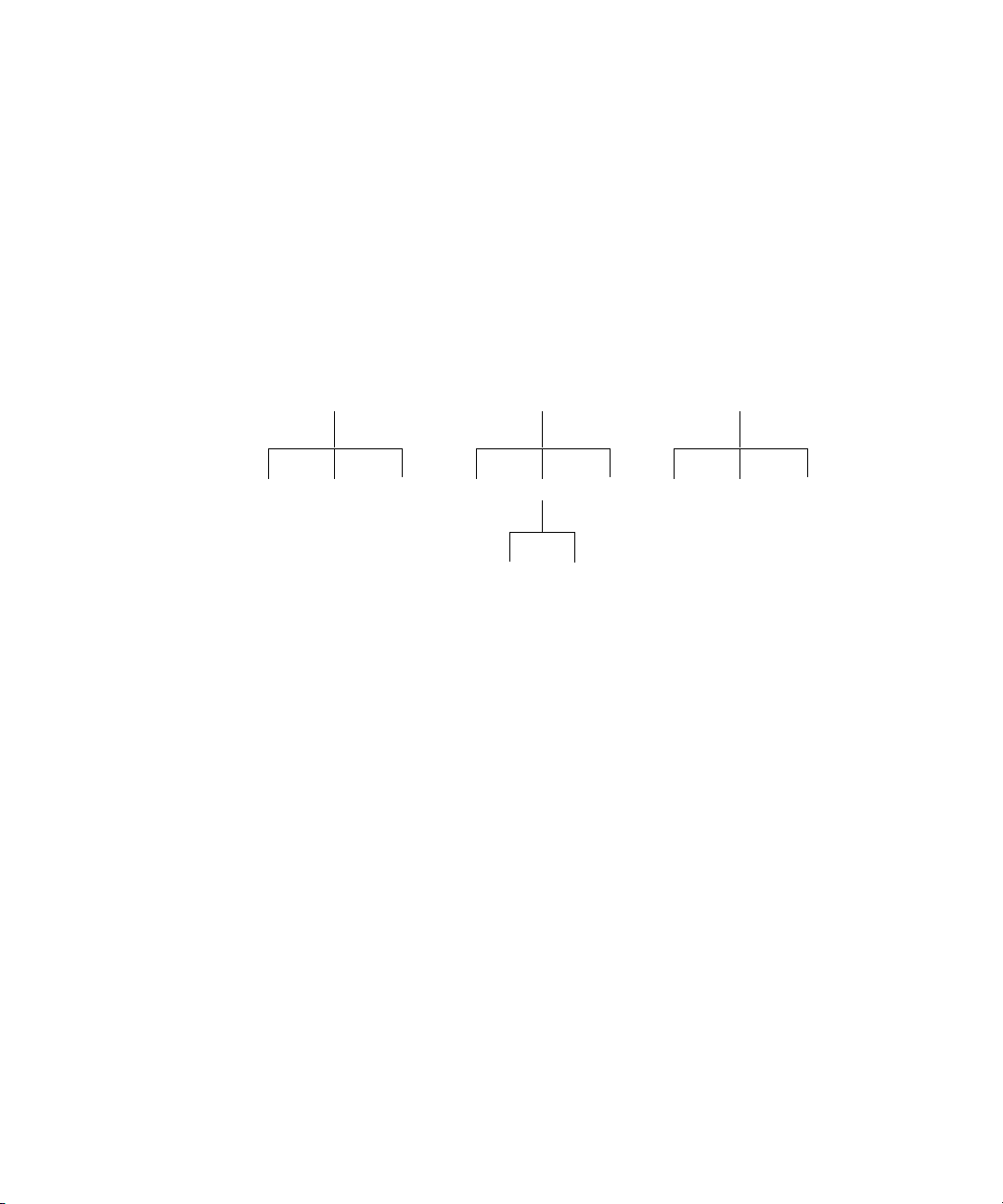
“B” Subsystem
:G :I:H
:M
:N=:B:H:N
“A” Subsystem
:D :F:E
“C” Subsystem
:J :L=:C:L:K
An Introduction to the SCPI Language
Standard Commands for Programmable Instruments (SCPI) defines how you
communicate with an instrument from a bus controller. The SCPI language uses a
hierarchical structure similar to the file systems used by many bus controllers. The
command tree is organized with root-level commands (also called subsystems)
positioned at the top, with multiple levels below each root-level command. You
must specify the complete path to execute the individual lower-level commands.
Figure 1-1 Hierarchical structure of SCPI
Mnemonic forms
Each keyword has both a long form and a short form. A standard notation is used
to differentiate the short-form keyword from the long-form keyword. The long
form of the keyword is shown, with the short form portion shown in upper-case
characters, and the rest of the keyword shown in lower-case characters. For
example, the short form of TRIGger is TRIG.
Using a colon (:)
When a colon is the first character of a command keyword, it indicates that the
next command mnemonic is a root-level command. When a colon is inserted
between two command mnemonics, the colon moves the path down one level in
the present path (for the specified root-level command) of the command tree. You
must separate command mnemonics from each other using a colon. You can omit
the leading colon if the command is the first of a new program line.
18 U8480 Series Programming Guide
Page 19

Using a semicolon (;)
NOTE
Use a semicolon to separate two commands within the same command string.
The semicolon does not change the present path specified. For example, the
following two statements are equivalent. Note that in the first statement, the first
colon is optional but the third is compulsory.
SENS:AVER ON;SENS:AVER:COUN 1
SENS:AVER ON;AVER:COUN 1
Using a comma (,)
If a command requires more than one parameter, you must separate adjacent
parameters using a comma.
Using whitespace
You must use whitespace characters, [tab] or [space], to separate a parameter
from a command keyword. Whitespace characters are generally ignored only in
parameter lists.
U8480 Series Remote Operation 1
Using “?” commands
The bus controller may send commands at any time, but a SCPI instrument may
only send responses when specifically instructed to do so. Only query commands
(commands that end with a “?”) instruct the instrument to send a response
message. Queries return either measured values or internal instrument settings.
If you send two query commands without reading the response from the first,
then attempt to read the second response, you may receive some data from the
first response followed by the complete second response. To avoid this, do not
send a query command without reading the response. When you cannot avoid
this situation, send a device clear before sending the second query command.
U8480 Series Programming Guide 19
Page 20

1 U8480 Series Remote Operation
Using “*” commands
Commands starting with a “*” are called common commands. They are required
to perform the identical function for all instruments that are compliant with the
IEEE-488.2 interface standard. The “*” commands are used to control reset,
self-test, and status operations in the U8480 Series.
Syntax conventions
Throughout this guide, the following conventions are used for the SCPI command
syntax.
– Square brackets ([]) indicate optional keywords or parameters.
– Braces ({}) enclose one or more parameters that may be included zero or more
times.
– Triangle brackets (<>) indicate that you must substitute a value for the
enclosed parameter.
– Bars (|) can be read as “or” and are used to separate alternative parameter
options.
Syntax diagram conventions
– Solid lines represent the recommended path.
– Ovals enclose command mnemonics. The command mnemonic must be
entered exactly as shown.
– Dotted lines indicate an optional path for bypassing secondary keywords.
– Arrows and curved intersections indicate command path direction.
SCPI data types
The SCPI language defines different data formats for use in program messages
and response messages. Instruments are flexible listeners and can accept
commands and parameters in various formats. However, SCPI instruments are
precise talkers. This means that SCPI instruments always respond to a particular
query in a predefined, rigid format.
20 U8480 Series Programming Guide
Page 21
U8480 Series Remote Operation 1
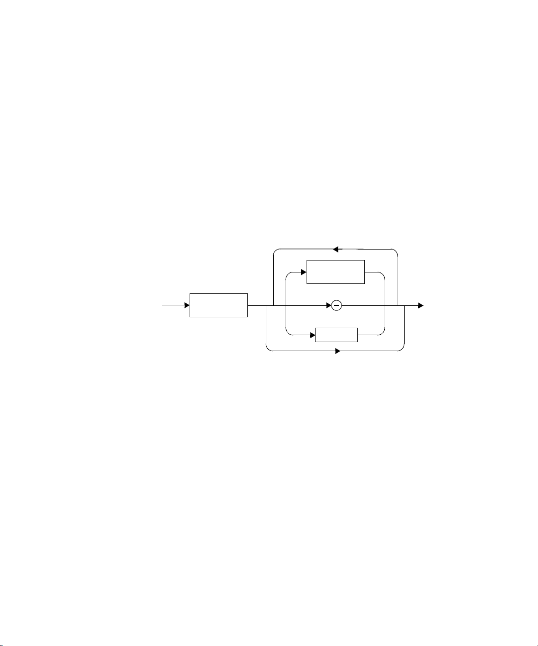
<digit>
<upper-case
alpha>
<upper-case
alpha>
<boolean> definition
Throughout this document, <boolean> is used to represent ON|OFF|<NRf>.
Boolean parameters have a value of 0 or 1 and are unitless. ON corresponds to 1
and OFF corresponds to 0.
On input, an <NRf> is rounded to an integer. A nonzero result is interpreted as 1.
Queries always return a 1 or 0, never ON or OFF.
<character_data> definition
Throughout this document, <character_data> is used to represent character
data, that is, A-Z, a-z, 0-9, and _ (underscore). For example: START and R6_5F.
The format is defined as follows:
Figure 1-2 Format of <character_data>
<NAN> definition
Not a number (NAN) is represented as 9.91E37. Not a number is defined in
IEEE 754.
U8480 Series Programming Guide 21
Page 22
1 U8480 Series Remote Operation
A/a
B/b
C/c
D/d
E/e
F/f
<digit>
H/h
1
2
3
4
5
6
0
7
Q/q
0
1
#
B/b
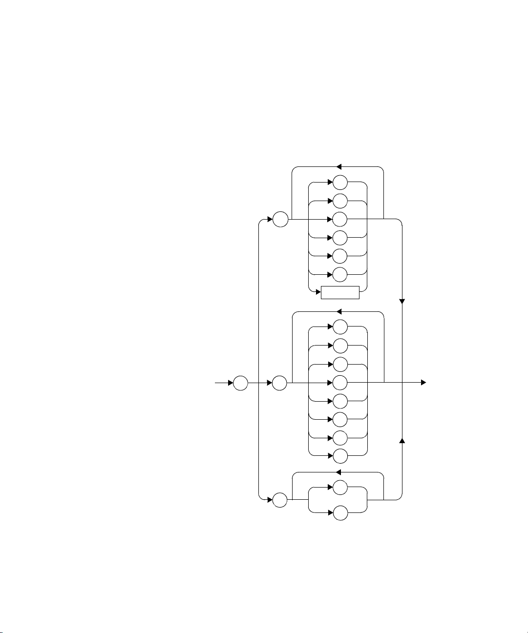
<non-decimal numeric> definition
Throughout this document, <non-decimal numeric> is used to represent numeric
information in bases other than ten (that is, hexadecimal, octal, and binary). The
following syntax diagram shows the standard for these three data structures. For
example: #HA2F, #ha4e, #Q62, #q15, #B01011.
Figure 1-3 Format of <non-decimal numeric>
22 U8480 Series Programming Guide
Page 23
U8480 Series Remote Operation 1
digit
+
digit
+
digit
Refer to section 7.7.4.1 of IEEE 488.2 for further details.
<NRf> definition
Throughout this document, <NRf> is used to denote a flexible numeric
representation. For example: +200; –56; +9.9E36. Refer to section 7.7.2.1 of IEEE
488.2 for further details.
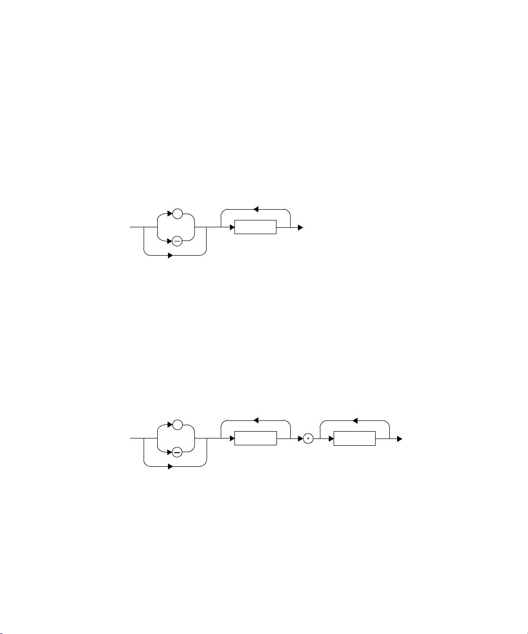
<NR1> definition
Throughout this document, the <NR1> numeric response data is defined as:
Figure 1-4 Format of <NR1>
For example:
– 146
– +146
– –12345
Refer to section 8.7.2 of IEEE 488.2 for further details.
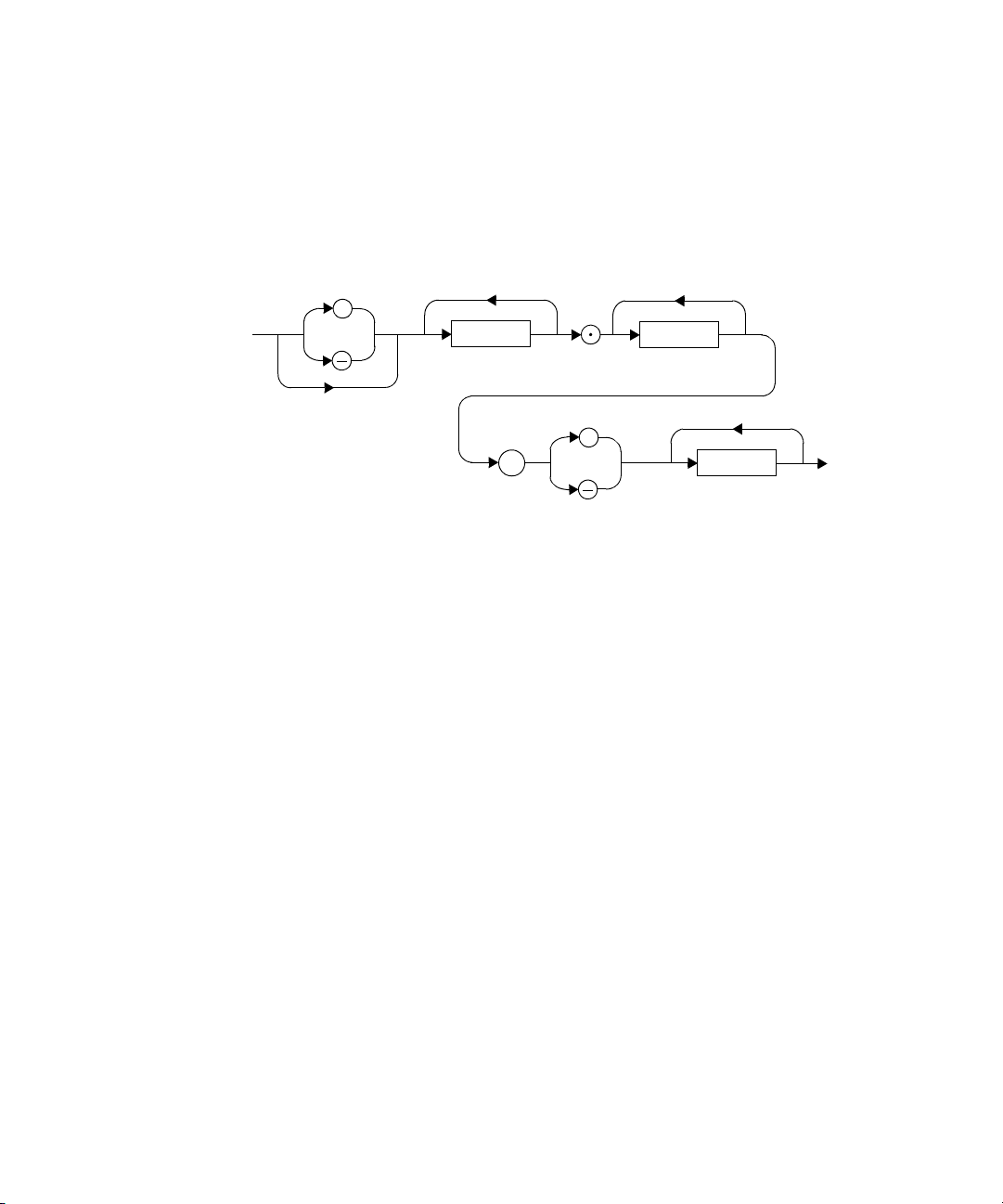
<NR2> definition
Throughout this document, the <NR2> numeric response data is defined as:
Figure 1-5 Format of <NR2>
For example:
– 12.3
– +1.2345
– –0.123
U8480 Series Programming Guide 23
Page 24
1 U8480 Series Remote Operation
digit
+
digit
digit
+
E
Refer to section 8.7.3 of IEEE 488.2 for further details.
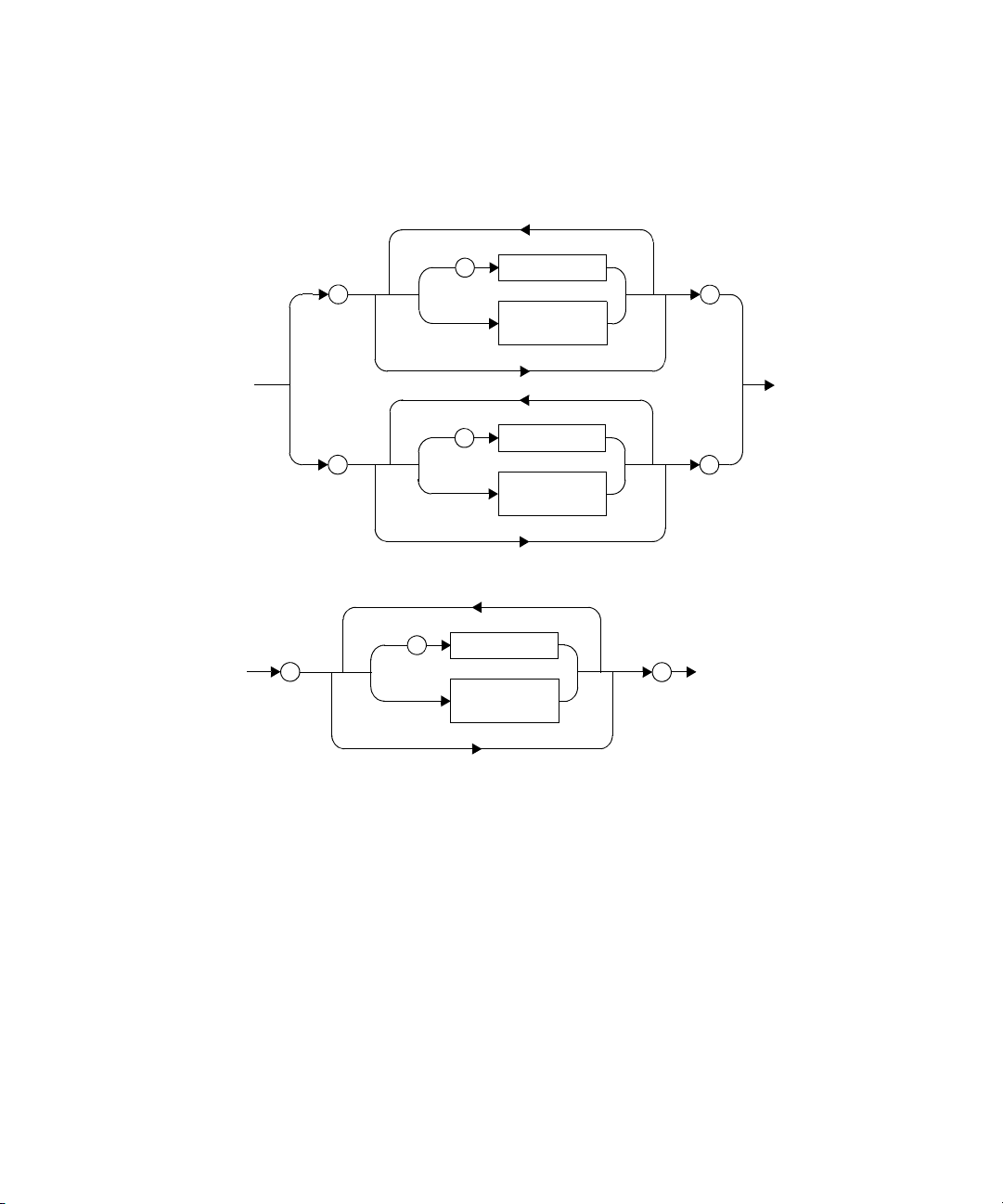
<NR3> definition
Throughout this document, the <NR3> numeric response data is defined as:
Figure 1-6 Format of <NR3>
For example:
– 1.23E+6
– 123.4E-54
– –1234.567E+90
Refer to section 8.7.4 of IEEE 488.2 for further details.
<numeric_value> definition
Throughout this document, the decimal numeric element is abbreviated to
<numeric_value>. For example: <NRf>, MINimum, MAXimum, DEFault, or Not A
Number (NAN).
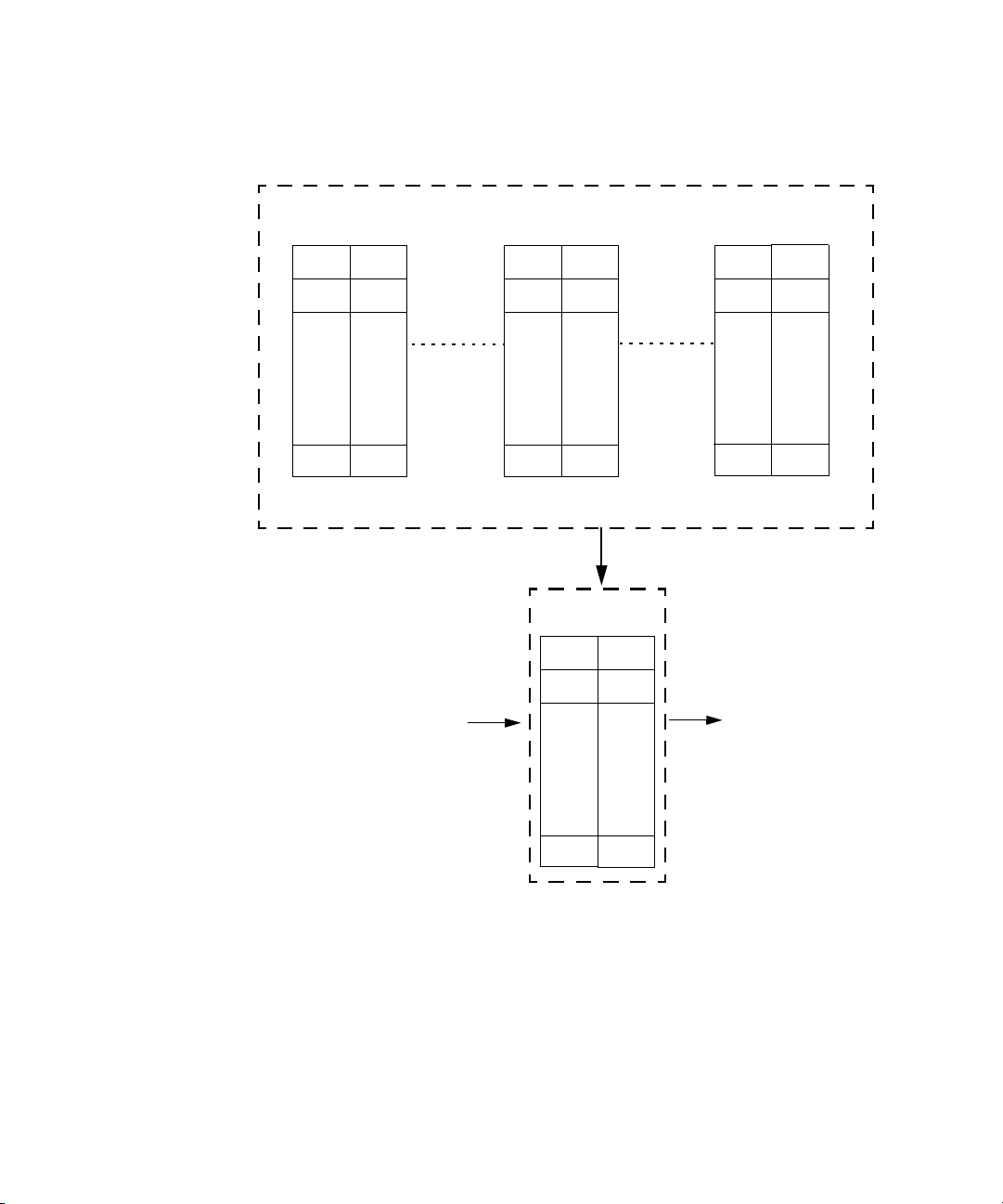
<string> definition
Throughout this document, <string> is used to represent 7-bit ASCII characters.
24 U8480 Series Programming Guide
Page 25
The format is defined as:
<inserted “>
<non-double
quote char>
“
“
“
<inserted “>
<non-double
quote char>
“
“
“
<inserted '>
<non-single
quote char>
'
'
'
Program Data
Response Data
U8480 Series Remote Operation 1
Figure 1-7 Format of <string>
Input message terminators
Program messages sent to a SCPI instrument must terminate with a <newline>
character. The IEEE.488 EOI (end or identify) signal is interpreted as a <newline>
character and may also be used to terminate a message in place of the <newline>
character. A <carriage return> followed by a <newline> is also accepted. Many
programming languages allow you to specify a message terminator character or
EOI state to be automatically sent with each bus transaction. Message
termination always sets the current path back to the root-level.
U8480 Series Programming Guide 25
Page 26

1 U8480 Series Remote Operation
Zeroing and Calibrating the U8480 Series
The U8480 Series does not require manual calibration. It is equipped with a highly
stable and accurate Internal Reference circuitry so that calibration can be
performed without an external 50 MHz 1 mW power reference.
Zeroing must be performed on the U8480 Series without the presence of RF
power at the U8480 Series input.
Zeroing
Zeroing adjusts the U8480 Series for a zero power reading. Input power to the
U8480 Series must not be present while zeroing is performed.
The CALibration[1]:ZERO:AUTO ONCE command causes the U8480 Series to
perform its zeroing routine, assuming that there is no power being applied to the
U8480 Series.
Zeroing takes approximately 15 seconds to complete.
Zeroing of the U8480 Series is recommended:
– upon power up.
– when a 5
– every 24 hours.
ο
C change in temperature occurs.
– prior to measuring low-level signals (for example, lowest 10 dB of the dynamic
range).
– when switching from or to the fast measurement mode (SENSe:MRATe FAST).
Calibration
The CALibration:AUTO ONCE command is used to calibrate the U8480 Series.
The U8480 Series performs an internal or external calibration:
– Internal calibration (CALibration:TYPE INT) utilizes the Internal Reference
Circuitry to perform calibration, and it does not require a 50 MHz 1 mW power
reference. Internal calibration is not impacted by the input power to the U8480
Series.
26 U8480 Series Programming Guide
Page 27

U8480 Series Remote Operation 1
– External calibration (CALibration:TYPE EXT) enables the U8480 Series to
perform calibration with a 50 MHz 1 mW power reference or a suitable power
reference.
Internal calibration is the default calibration type upon power up.
Internal calibration of the U8480 Series occurs automatically:
– upon power up.
– when a 10
ο
C change in temperature has occurred since the last calibration.
The CALibration:AUTO [ON|OFF|1|0] command controls the automatic
setting of the internal calibration.
Internal calibration takes approximately 1.5 s to complete, while external
calibration takes approximately 15 s to complete.
Calibration sequence
You can perform a complete calibration sequence in a single query:
CALibration[1][:ALL]?
This query is only applicable for the internal calibration as the U8480 Series does
not have control of the power reference in the external calibration. The calibration
sequence consists of:
1 Zeroing the U8480 Series (CALibration:ZERO:AUTO ONCE) and
2 Calibrating the U8480 Series (CALibration:AUTO ONCE).
This query enters a number into the output buffer when the sequence has
completed. If the result is 0, the sequence is successful. If the result is 1, the
sequence has failed.
Refer to “CALCulate Command Subsystem” on page 94 for further information.
U8480 Series Programming Guide 27
Page 28

1 U8480 Series Remote Operation
Making Measurements
The MEASure? query and CONFigure command provide a straightforward method
to program the U8480 Series for measurements. You can select the measurement
expected power level and resolution in one command. The U8480 Series
automatically presets other measurement parameters to default values as shown
in Table 1-1 below.
Tab le 1-1 MEASure? and CONFigure preset states
Command MEASure? and CONFigure settings
Trigger source
(TRIGger[1]:SOURce)
Filter
([SENSe[1]:]AVERage:COUNt:AUTO)
Immediate
On
Filter state
([SENSe[1]:]AVERage[:STATe])
Trigger cycle
(INITiate[1]:CONTinuous)
Trigger delay
(TRIGger[1]:DELay:AUTO)
An alternative method to program the U8480 Series is to use the lower-level
commands. The advantage of using the lower-level commands over the
MEASure? query and CONFigure command is that they give you more precise
control of the U8480 Series. As shown in Table 1-1, the CONFigure command
presets various states in the U8480 Series. It may be likely that you do not want to
preset these states.
Using MEASure?
The simplest way to program the U8480 Series for measurements is by using the
MEASure? query. However, this query does not offer much flexibility. When you
execute the query, the U8480 Series selects the best settings for the requested
configuration and immediately performs the measurement. You cannot change any
setting (other than the expected power value and resolution) before the
measurement is taken. This means you cannot finetune the measurement; for
On
Off
On
28 U8480 Series Programming Guide
Page 29

U8480 Series Remote Operation 1
MEAS?
MEAS? DEF,DEF,(@1)
specifies source list
example, you cannot change the filter length. To make more flexible and accurate
measurements, use the CONFigure command. MEASure? is a compound command
which is equivalent to an ABORt, followed by a CONFigure and a READ?
MEASure? examples
The following examples describe how to use the MEASure? query to make a
measurement. These examples configure the U8480 Series for a measurement (as
described in each individual example), automatically place the U8480 Series in
the “wait-for-trigger” state, trigger the U8480 Series to take one reading, and
then send the reading to the output buffer.
For further information on the
Commands” on page 72.
MEASure? query, refer to the “Measurement
Example 1 - The simplest method
The following shows the simplest method of making measurements using MEAS?
Example 2 - Specifying the source list parameter
The MEASure? query has three optional parameters: an expected power value, a
resolution, and a source list. These parameters must be entered in the specified
order. Parameters may be defaulted from the right by omitting them, or anywhere
by substituting the keyword DEFault. The parameter DEFault is used as a
placeholder.
The source list parameter is used to specify a measurement channel. The U8480
Series supports only one channel. Therefore, the only valid value is (@1). The
expected power and resolution parameters are set to their default values, leaving
them at their current settings.
U8480 Series Programming Guide 29
Page 30

1 U8480 Series Remote Operation
MEAS? -20,DEF,(@1)
specifies expected power value
MEAS? DEF,3
specifies resolution setting
Example 3 - Specifying the expected power parameter
The previous example details the three optional parameters which can be used
with the MEASure? query. The first optional parameter is used to enter an expected
power value.
The following example uses the expected value parameter to specify a value of
-20 dBm. The resolution parameter is set to its default value, leaving it at its
current setting.
Example 4 - Specifying the resolution parameter
The previous examples detail the use of the expected value and source list
parameters. The resolution parameter is used to set the resolution. This parameter
does not affect the resolution of the data; however it does affect the
auto-averaging setting (refer to “Auto- aver agin g mode” on page 43).
The following example uses the resolution parameter to specify a resolution
setting of 3. This setting represents three significant digits if the measurement unit
is W, and 0.01 dB if the unit is dBm. Refer to Chapter 2, “MEASurement
Commands” on page 71 for further details on the resolution parameter. The
expected power and source list parameters are set to their default values in the
example. The expected power value remains unchanged at its current setting.
Note that as the source list parameter is the last specified parameter, you do not
have to specify DEF.
30 U8480 Series Programming Guide
Page 31

Using the CONFigure command
When you execute this command, the U8480 Series presets the optimum settings
for the requested configuration (like the MEASure? query). However, the
measurement is not automatically started, and you can change the measurement
parameters before making measurements. This allows you to change the U8480
Series configuration from the preset conditions. The U8480 Series offers a variety
of low-level commands in the SENSe, CALCulate, and TRIGger command
subsystems. For example, if you want to change the measurement filter length,
use the [SENSe[1]:]AVERage:COUNt command.
Use the INITiate command or the READ? query to initiate the measurement.
Using READ?
CONFigure does not take the measurement. One method of obtaining a result is to
use the READ? query. The READ? query takes the measurement using the
parameters set by the CONFigure command and then sends the reading to the
output buffer. New data is obtained using the READ? query.
Using INITiate and FETCh?
CONFigure does not take the measurement. One method of obtaining the result is
to use the INITiate command and FETCh? query. The INITiate command
causes the measurement to be taken. The FETCh? query retrieves a reading when
the measurement is complete and sends the reading to the output buffer. FETCh?
can be used to retrieve the measurement results in a number of different formats
without taking fresh data for each measurement.
U8480 Series Remote Operation 1
CONFigure examples
The following examples describe how to use the CONFigure commands together
with the INITiate, READ?, and FETCh? commands to make measurements.
For further information on the CONFigure commands, refer to Chapter 2,
MEASurement Commands.
Example 1 - The simplest method
This example shows the simplest method of querying the measurement results.
U8480 Series Programming Guide 31
Page 32

1 U8480 Series Remote Operation
Using READ?
*RST Resets the U8480 Series.
CONF Configures the measurement -sets to a single measurement by
default.
READ? Initiates and retrieves the measurement.
Using INITiate and FETCh?
*RST Resets the U8480 Series.
CONF Configures the measurement -sets to a single measurement by
default.
INIT Sets it to wait for a trigger state.
FETC? Triggers a measurement, and then retrieves the measurement
reading.
Example 2 - Specifying the source list parameter
The CONFigure command and READ? query have three optional parameters: an
expected power value, a resolution, and a source list. These parameters must be
entered in the specified order. Parameters may be defaulted from the right by
omitting them, or anywhere by substituting the keyword DEFault. The parameter
DEFault is used as a placeholder.
The following examples use the source list parameter to specify the measurement.
The expected power and resolution parameters are set to their default values,
leaving them at their current settings.
Although the READ? and FETCh? queries have three optional parameters, it is not
necessary to define them as shown in these examples. If they are defined, they
must be identical to those defined in the CONFigure command, otherwise an error
will occur.
Using READ?
ABOR Aborts the measurement.
CONF DEF,DEF,(@1) Configures the measurement to make a measurement
using the current expected power and resolution
settings.
READ? Initiates and retrieves the measurement.
32 U8480 Series Programming Guide
Page 33

U8480 Series Remote Operation 1
Using INITiate and FETCh?
ABOR Aborts the measurement.
CONF DEF,DEF,(@1) Configures the measurement to measure using the
current expected power and resolution settings.
INIT Sets it to wait for a trigger state.
FETC? DEF,DEF,(@1) Triggers a measurement, and then retrieves the
measurement reading.
Example 3 - Specifying the expected power parameter
The previous example details the three optional parameters which can be used
with the CONFigure command and READ? query. The first optional parameter is
used to enter an expected power value.
The following example uses the expected value parameter to specify an expected
power of –20 dBm. The resolution parameter is set to its default value, leaving it
at its current setting.
Using READ?
ABOR Aborts the measurement.
CONF -20,DEF,(@1) Configures the measurement to use an expected
power of –20 dBm and the current resolution
setting.
READ? Initiates and retrieves the measurement.
Some finetuning of the measurements can be performed using the CONFigure
command and READ? query. For example, in the earlier program segment, some
finetuning can be performed by setting the filter length to 1024 and the trigger
delay off.
1 ABOR
2 CONF -20,DEF,(@1)
3 SENS:AVER:COUN 1024
4 TRIG:DEL:AUTO OFF
5 READ?
U8480 Series Programming Guide 33
Page 34

1 U8480 Series Remote Operation
Using INITiate and FETCh?
ABOR Aborts the measurement.
CONF -20,DEF,(@1) Configures the measurement to use an expected
INIT Sets it to wait for a trigger state.
FETC? -20,DEF,(@1) Triggers a measurement, and then retrieves the
Some finetuning of measurements can be carried out using the CONFigure
command, INITiate command, and FETCh? query. For example, in the above
program segment, some finetuning can be carried out by setting the filter length
to 1024 and the trigger delay off.
1 ABOR
2 CONF -20,DEF,(@1)
3 SENS:AVER:COUN 1024
4 TRIG:DEL:AUTO OFF
power of –20 dBm and the current resolution
setting.
measurement reading.
5 INIT
6 FETC? -20,DEF,(@1)
Example 4 - Specifying the resolution parameter
The previous examples detail the use of the expected value and source list
parameters. The resolution parameter is used to set the measurement resolution.
This parameter does not affect the resolution of the data; however it does affect
the auto-averaging setting.
The following example uses the resolution parameter to specify a resolution
setting of 3. This setting represents three significant digits if the measurement unit
is W, and 0.01 dB if the unit is dBm (for further details on the resolution
parameter, refer to the commands in Chapter 2, MEASurement Commands). Also,
in this example, the expected power and source list parameters are set to their
default values. The expected power value is left unchanged at its current setting.
Note that as the source list parameter is the last specified parameter, you do not
have to specify DEF.
34 U8480 Series Programming Guide
Page 35

U8480 Series Remote Operation 1
Using READ?
ABOR Aborts the measurement.
CONF DEF,3 Configures the measurement to use the current setting of
the expected power and source list and a resolution
setting of 3.
READ? Initiates and retrieves the measurement.
Some finetuning of the above program segment can be carried out, for example,
by setting the trigger delay off, as shown below.
1 ABOR
2 CONF DEF,3
3 TRIG:DEL:AUTO OFF
4 READ?
Using INITiate and FETCh?
ABOR
CONF DEF,3
INIT
FETC? DEF,3
Some finetuning of the above program segment can be carried out, for example,
by setting the trigger delay off, as shown below.
1 ABOR
2 CONF DEF,3
3 TRIG:DEL:AUTO OFF
4 INIT
5 FETC? DEF,3
U8480 Series Programming Guide 35
Aborts the measurement.
Configures the measurement to use the current setting
of the expected power and source list and a resolution
setting of 3.
Sets it to wait for a trigger state.
Triggers a measurement, and then retrieves the
measurement reading.
Page 36

1 U8480 Series Remote Operation
Using Frequency-Dependent Offset Tables
This section describes how to use frequency-dependent offset tables. These
tables give you the ability to compensate for frequency effects in your test setup.
Overview
If the [SENSe[1]:]CORRection:CSET2:STATe command is OFF, the
frequency-dependent offset tables are not used. When
[SENSe[1]:]CORRection:CSET2:STATe is ON, the frequency-dependent offset
tables are used, providing you with a quick and convenient method of
compensating for your external test setup over a range of frequencies. Note that
when selected, frequency-dependent offset correction is IN ADDITION to any
correction applied for sensor frequency response. The U8480 Series is capable of
storing 10 frequency-dependent offset tables of 80 frequency points each.
To use the frequency-dependent offset table:
1 Edit a frequency-dependent offset table if necessary.
2 Select the frequency-dependent offset table.
3 Enable the frequency-dependent offset table.
4 Zero and calibrate the U8480 Series.
5 Specify the frequency of the signal you want to measure. The required offset is
automatically set by the U8480 Series from the frequency-dependent offset
table.
6 Make the measurement.
The figure below illustrates how frequency-dependent offset tables operate.
36 U8480 Series Programming Guide
Page 37
U8480 Series Remote Operation 1
TABLE N
FREQ
FREQ
1
.
.
.
.
.
.
.
.
.
.
.
FREQ
2
80
OFFSET
OFFSET
1
.
.
.
.
.
.
.
.
.
.
.
80
TABLE 1
FREQ
FREQ
1
.
.
.
.
.
.
.
.
.
.
.
FREQ
2
80
OFFSET
OFFSET
1
.
.
.
.
.
.
.
.
.
.
.
2
80
TABLE 10
FREQ
FREQ
1
.
.
.
.
.
.
.
.
.
.
.
FREQ
2
80
OFFSET
OFFSET
1
.
.
.
.
.
.
.
.
.
.
.
OFFSET
2
80
OFFSET = Frequency-dependent offset
FREQ
FREQ
1
.
.
.
.
.
.
.
.
.
.
.
FREQ
2
80
OFFSET
OFFSET
1
.
.
.
.
.
.
.
.
.
.
.
OFFSET
2
80
Frequency of the signal you want
to measure
TABLE SELECTE D
OFFSET
2
OFFSET
Frequency-dependent
offset is used to make
measurements using
linear interpolation
U8480 Series Programming Guide 37
Figure 1-8 Frequency-dependent offset tables
Page 38

1 U8480 Series Remote Operation
Editing frequency-dependent offset tables
It is not possible to create any additional frequency-dependent offset tables.
However, the 10 existing tables can be edited using the MEMory command
subsystem. To do this:
1 Select one of the existing tables using
MEMory:TABLe:SELect <“character_data”>
For information on naming frequency-dependent offset tables, see “Naming
frequency-dependent offset tables” on page 40. For information on the current
names which you can select, refer to “Listing the frequency-dependent offset
table names” on page 39.
2 Enter the frequency data using
MEMory:TABLe:FREQuency <numeric_value>{,<numeric_value>}
3 Enter the offset factors as shown in the table below using
MEMory:TABLe:GAIN <numeric_value>{,<numeric_value>}
Frequency Offset
Frequency 1 Offset 1
Frequency 2 Offset 2
""
Frequency n Offset n
4 If required, rename the frequency-dependent offset table using
MEMory:TABLe:MOVE <“character_data”>,<“character_data”>. The first
<string> parameter identifies the existing table name, and the second
identifies the new table name.
38 U8480 Series Programming Guide
Page 39

U8480 Series Remote Operation 1
NOTE
The legal frequency unit multipliers are any of the IEEE unit multipliers, for
example, KHZ, MHZ, and GHZ. If no units are specified, the U8480 Series
assumes the data is Hz.
PCT is the only legal unit for offset factors and can be omitted.
The frequency and offset data must be within range. Refer to the individual
commands in Chapter 8 for their specified ranges.
Ensure that the frequency points you use cover the frequency range of the
signals you want to measure. If you measure a signal with a frequency outside
the frequency range defined in the frequency-dependent offset table, then the
U8480 Series uses the highest or lowest frequency point in the table to calculate
the offset.
To make subsequent editing of a frequency-dependent offset table simpler, it is
recommended that you retain a copy of your data in a program.
Listing the frequency-dependent offset table names
To list the frequency-dependent offset tables currently stored in the U8480 Series,
use the following query:
MEMory:CATalog:TABLe?
The U8480 Series returns the data in the form of two numeric parameters and a
string list representing all stored tables:
– <numeric_value>,<numeric_value>{,<string>}
The first numeric parameter indicates the amount of memory, in bytes, used
for storage of tables. The second parameter indicates the memory, in bytes,
available for tables.
Each string parameter returned indicates the name, type, and size of a stored
frequency-dependent offset table:
– <string>,<type>,<size>
The <string>, <type> and <size> are all character data. The <type> is always
TABL. The <size> is indicated in bytes.
For example, a sample of the response may look like:
560,8020,”Offset_1,TABL,220”,”Offset_2,TABL,340” ....
U8480 Series Programming Guide 39
Page 40

1 U8480 Series Remote Operation
Naming frequency-dependent offset tables
To rename a frequency-dependent offset table use
MEMory:TABLe:MOVE <string>,<string>
The first <string> parameter identifies the existing table name, and the second
identifies the new table name.
The following rules apply to frequency-dependent offset table names:
– Table names use a maximum of 12 characters.
– All characters must be upper or lower case alphabetic characters, or numeric
(0-9), or an underscore (_).
– No spaces are allowed in the name.
Reviewing table data
To review the data stored in a frequency-dependent offset table, use the following
command and queries:
MEMory:TABLe:SELect “Offset1”
Selects the frequency-dependent offset table named “Offset1”.
MEMory:TABLe:SELect?
Returns the name of the currently selected table.
MEMory:TABLe:FREQuency:POINts?
Returns the number of stored frequency points.
MEMory:TABLe:FREQuency?
Returns the frequencies stored in the frequency-dependent offset table (in Hz).
MEMory:TABLe:GAIN[:MAGNitude]:POINts?
Returns the number of offset factor points stored in the frequency-dependent
offset table.
MEMory:TABLe:GAIN[:MAGNitude]?
Returns the offset factors stored in the frequency-dependent offset table.
Modifying data
If you need to modify the frequency and offset factor data stored in a
frequency-dependent offset table, you need to resend the complete data lists.
If you have retained the original data in a program, edit the program and resend
the data.
40 U8480 Series Programming Guide
Page 41

U8480 Series Remote Operation 1
Selecting a frequency-dependent offset table
After you have created the frequency-dependent offset table, you can select it
using the following command:
[SENSe[1]:]CORRection:CSET2[:SELect] <string>
To find out which frequency-dependent offset table is currently selected, use the
following query:
[SENSe[1]:]CORRection:CSET2[:SELect]?
Enabling a frequency-dependent offset table
To enable the frequency-dependent offset table, use the following command:
[SENSe[1]:]CORRection:CSET2:STATe ON
If you set [SENSe[1]:]CORRection:CSET2:STATe to ON and no
frequency-dependent offset table is selected, error –221, “Settings conflict” occurs.
Making the measurement
To make the power measurement, set the U8480 Series for the frequency of the
signal you want to measure. The U8480 Series automatically sets the offset factor.
Use either INITiate and FETCh?, or READ? to initiate the measurement as shown
in the following program segments:
INITiate example
ABOR
CONF DEF,1,(@1)
CORR:CSET2:SEL “Offset1”
CORR:CSET2:STAT ON
FREQ 50MHZ
INIT:IMM
FETC?
U8480 Series Programming Guide 41
Page 42

1 U8480 Series Remote Operation
NOTE
READ? example
ABOR
CONF DEF,2,(@1)
CORR:CSET2:SEL “Offset1”
CORR:CSET2:STAT ON
FREQ 50MHZ
READ?
If the measurement frequency does not correspond directly to a frequency in the
frequency- dependent offset table, the U8480 Series calculates the offset using
linear interpolation.
If you enter a frequency outside the frequency range defined in the
frequency-dependent offset table, then the U8480 Series uses the highest or
lowest frequency point in the table to set the offset.
To find out the value of the offset being used by the U8480 Series to make a
measurement, use the following query:
[SENSe[1]:]CORRection:FDOFfset|GAIN4[:INPut][:MAGNitude]?
The response may be an interpolated value.
42 U8480 Series Programming Guide
Page 43

Setting the Averaging
This section provides an overview of setting the averaging. For more detailed
information on this feature, refer to the individual commands in Chapter 8, SENSe
Subsystem.
Averaging
The U8480 Series has a digital filter to average power readings. The number of
readings averaged can range from 1 to 1024. This filter is used to reduce noise,
obtain the desired resolution, and to reduce the jitter in the measurement results.
However, the time to take the measurement is increased. You can select the filter
length, or you can set the U8480 Series to the auto-filter mode. To enable and
disable averaging, use the following command:
[SENSe[1]:]AVERage[:STATe] <boolean>
Auto-averaging mode
To enable or disable auto-filter mode, use the following command:
U8480 Series Remote Operation 1
[SENSe[1]:]AVERage:COUNt:AUTO <boolean>
When the auto-filter mode is enabled, the U8480 Series automatically sets the
number of readings averaged together to satisfy the filtering requirements for
most power measurements. The number of readings averaged together depends
on the resolution and the power level currently being measured. Refer to
“Auto-Averaging Settings” on page 374 for more information.
U8480 Series Programming Guide 43
Page 44

1 U8480 Series Remote Operation
Filter length
You specify the filter length using the following command:
[SENSe[1]:]AVERage:COUNt <numeric_value>
The range of values for the filter length is 1 to 1024. Specifying this command
disables automatic filter length selection. Increasing the value of the filter length
reduces measurement noise. However, the time to take the measurement is
increased.
Tab le 1-2 Settling time for normal speed, ×2 speed, and fast speed
Number of averages
1 0.15 0.14 0.003
2 0.23 0.16 0.005
4 0.33 0.23 0.009
8 0.53 0.33 0.018
16 0.90 0.51 0.036
32 1.68 0.91 0.069
64 3.24 1.70 0.134
128 6.44 3.28 0.265
256 12.7 6.45 0.528
512 25.3 12.7 1.05
1024 50.5 25.3 2.10
[a] Manual filter, 10 dB decreasing power step
Settling time
(Normal speed)
[a]
(s)
Settling time
(´2 speed)
[a]
(s)
Settling time
(Fast speed)
[a]
(s)
44 U8480 Series Programming Guide
Page 45

Setting Offsets
NOTE
Channel offsets
The U8480 Series can be configured to compensate for signal loss or gain in your
test setup (for example, to compensate for the loss of a 10 dB attenuator). You use
the SENSe command subsystem to configure the U8480 Series. Gain and loss
correction are a coupled system. If you enter an offset value, the state is
automatically enabled. However, it can be enabled and disabled using the
[SENSe[1]:]CORRection:GAIN2:STATe <boolean> command.
To enter a LOSS value, you can enter a negative value in the command:
[SENSe[1]:]CORRection:GAIN2[:INPut][:MAGNitude] <numeric_value>
U8480 Series Remote Operation 1
U8480 Series Programming Guide 45
Page 46
1 U8480 Series Remote Operation
Amplitude
Frequency
o
o
o
o
o
o
o
Fail
Fail
Setting Measurement Limits
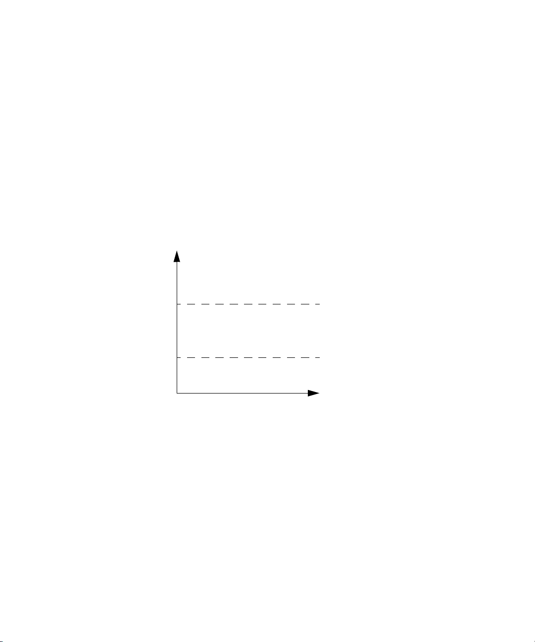
You can configure the U8480 Series to detect when a measurement is outside of a
predefined upper and/or lower limit value.
Setting limits
The U8480 Series can be configured to verify the power being measured against
an upper and/or lower limit value. The range of values that can be set for lower
and upper limits is –150.00 dBm to +230.00 dBm. The default upper limit is
+90.00 dBm, and the default lower limit is –90.00 dBm.
Figure 1-9 Limits checking results
The U8480 Series can be configured to verify the measurement in either Watts (W)
or dBm against the predefined upper and/or lower limit values. The upper and
lower limits can be set using the CALCulate[1]:LIMit:UPPer[:DATA] and
CALCulate[1]:LIMit:LOWer[:DATA] commands respectively. The range of
values that can be set for the limits and default values depends on the
measurement unit that is currently selected (refer to Tab le 1-3).
46 U8480 Series Programming Guide
Page 47

U8480 Series Remote Operation 1
NOTE
Table 1-3 Range of values for measurement limits
Unit Maximum Minimum Default maximum Default minimum
dBm 230 dBm
W 1e20 W 1e–18 W 1e6 W 1e–12 W
An example of the programming sequence is shown as follows.
-> SYST:PRES DEF // Presets the U8480 Series.
-> UNIT:POW DBM // Sets the measurement unit to dBm.
-> CALC:LIM:STAT 1 // Enables the test limit feature.
-> CALC:LIM:LOW 4 // Sets the lower limit to 4 dBm.
-> CALC:LIM:UPP 10 // Sets the upper limit to 10 dBm.
The U8480 Series will start to monitor the RF power between 4 dBm (lower limit)
and 10 dBm (upper limit). RF power that is either <4 dBm or
>10 dBm will cause the U8480 Series to log an error.
–150 dBm
90 dBm
–90 dBm
“->” indicates the commands that you send to the U8480 Series.
Checking for limit failures
To check for limit failures, use the CALCulate[1]:LIMit:FAIL? and/or
CALCulate[1]:LIMit:FCOunt? queries.
The CALCulate[1]:LIMit:FAIL? query will return 1 if one or more limit failures
have occurred. If no limit failures have occurred, 0 will be returned.
The CALCulate[1]:LIMit:FCOunt? query will return the total number of limit
failures.
U8480 Series Programming Guide 47
Page 48

1 U8480 Series Remote Operation
An example of the programming sequence is shown as follows.
-> SYST:PRES DEF // Presets the U8480 Series.
-> TRIG:SOUR EXT // Sets the trigger source to external.
-> UNIT:POW DBM // Sets the measurement unit to dBm.
-> CALC:LIM:STAT 1 // Enables the test limit feature.
-> CALC:LIM:LOW 4 // Sets the lower limit to 4 dBm.
-> CALC:LIM:UPP 10 // Sets the upper limit to 10 dBm.
-> CALC:LIM:CLE:AUTO OFF // Disables auto-clearing of the fail counter.
-> CALC:LIM:CLE // Clears the fail counter of any limit failure.
Provides 5 dBm of RF power to the U8480 Series, followed by sending an
external trigger signal to the U8480 Series.
-> CALC:LIM:FAIL? // Checks for limit failures.
<– 0 // No limit failure, where the measured
-> CALC:LIM:FCO? // Checks the total number of limit failures.
<– 0 // No limit failure has been detected.
Provides 12 dBm of RF power to the U8480 Series, followed by sending an
external trigger signal to the U8480 Series.
-> CALC:LIM:FAIL? // Checks for limit failures.
<– 1 // Limit failures have been detected, where
-> CALC:LIM:FCO? // Checks the total number of limit failures.
<– 1 // One limit failure has been detected.
Provides 8 dBm of RF power to the U8480 Series, followed by sending an
external trigger signal to the U8480 Series.
-> CALC:LIM:FAIL? // Checks for limit failures.
<– 1 // No limit failure. “1” was caused by the
-> CALC:LIM:FCO? // Checks the total number of limit failures.
power is within the range of >4 dBm and
<10 dBm.
the measured power is
>10 dBm. Previous limit failures will not
be cleared.
previous limit failure.
48 U8480 Series Programming Guide
Page 49

U8480 Series Remote Operation 1
NOTE
NOTE
<– 1 // One limit failure has been detected.
Provides 2 dBm of RF power to the U8480 Series, followed by sending an
external trigger signal to the U8480 Series.
-> CALC:LIM:FAIL? // Checks for limit failures.
<– 1 // Limit failures have been detected, where
the measured power is
<4 dBm. Previous limit failures will not be
cleared.
-> CALC:LIM:FCO? // Checks the total number of limit failures.
<– 2 // Two limit failures have been detected.
“->” indicates the commands that you send to the U8480 Series.
“<-” indicates the response from the U8480 Series.
If TRIGger[1]:DELay:AUTO is set to ON, then the number of failures returned by
CALCulate[1]:LIMit:FCOunt? is affected by the current filter settings.
U8480 Series Programming Guide 49
Page 50

1 U8480 Series Remote Operation
Getting the Best Speed Performance
This section discusses the factors that influence the speed of operation (number
of readings/sec) of the U8480 Series.
The following factors are those which have the greatest effect upon measurement
speed (in no particular order):
– The selected measurement rate of either NORMal, DOUBle, or FAST.
– The trigger mode (for example, Free Run, Triggered Free Run, or Single Shot).
– The output format: ASCii
– The units used for the measurement.
– The command used to take a measurement.
In addition, there are other influences in the FAST
“Fast mode” on page 52.
The following paragraphs give a brief description of the above factors and how
they are controlled using SCPI.
Measurement rate
There are three possible speed settings: NORMal, DOUBle, and FAST. These are set
using the [SENSe[1]:]MRATe command.
In the NORMal and DOUBle modes, full instrument functionality is available, but in
the FAST mode, limits are disabled.
Refer to the specifications in the U8480 Series User’s Guide to determine the
influence of these speed settings on the accuracy and noise performance of the
U8480 Series.
Trigger mode
The U8480 Series has a very flexible triggering system. For simplicity, it can be
described as having three modes:
or REAL.
mode which are described in
– Free Run: When the U8480 Series is in the Free Run mode, it continuously
takes measurements. A measurement is in free run when
INITiate:CONTinuous is set to ON and TRIGger:SOURce is set to IMMediate.
50 U8480 Series Programming Guide
Page 51

U8480 Series Remote Operation 1
NOTE
– Triggered Free Run: When the U8480 Series is in the Triggered Free Run or
Continuous Trigger mode, it takes a new measurement each time a trigger
event is detected. A measurement is in triggered free run or continuous trigger
when INITiate:CONTinuous is set to ON and TRIGger:SOURce is not set to
IMMediate.
– Single Shot: When the U8480 Series is in the Single Shot mode, it takes a new
measurement when a trigger event is detected and then returns to the idle
state. A measurement is in single shot when INITiate:CONTinuous is set to
OFF. Note that a measurement can take several EXT triggers depending on the
filter settings. Refer to “TRIGger[1]:DELay:AUTO <boolean>” on page 311 for
further information.
A trigger event can be any of the following:
– The input signal meeting the trigger level criteria.
– Auto-level triggering being used.
–A TRIGger[1][:IMMediate] or *TRG command being sent.
– An external TTL level trigger being detected.
Trigger with delay
This can be achieved using the same sequences above (apart from the second)
with TRIG:DEL:AUTO set to ON. Also, the MEAS? query operates in the trigger with
delay mode.
In the trigger with delay mode, a measurement is not completed until the U8480
Series filter is full. In this way, the reading returned is guaranteed to be settled. In
all other modes, the result returned is simply the current result from the filter and
may or may not be settled. This depends on the current length of the filter and the
number of readings that have been taken since a change in power level.
With trigger with delay enabled, the measurement speed can be calculated
roughly using the following equation:
readings/sec = speed (as set by [SENSe[1]:]MRATe) / filter length
For example, with a filter length of 4 and [SENSe[1]:]MRATe set to NORMal,
approximately 5 readings/sec is calculated by the U8480 Series.
U8480 Series Programming Guide 51
Page 52

1 U8480 Series Remote Operation
Output format
The U8480 Series has two output formats for measurement results: ASCii and
REAL. These formats are selected using the FORMat command. When FORMat is set
to REAL, the returned result is in the IEEE-754 floating-point format (note that the
byte order can be changed using FORMat:BORDer).
The REAL format is likely to be required only for the FAST mode as it reduces the
amount of bus traffic.
Units
The U8480 Series can output results in either linear or log units. The internal units
are linear; therefore optimal performance is achieved when the results output are
also in linear units (since the overhead of performing a log function is removed).
Command used
In the Free Run mode, FETCh? must be used to return a result.
In other trigger modes, there are a number of queries that can be used, for
example, MEASure?, READ?, FETCh?. Note that the MEAS? and READ? queries are
compound commands — they perform a combination of other lower-level
commands. Typically, the best speed performance is achieved using the low-level
commands directly.
Trigger count
To get the fastest measurement speed, TRIG:COUNt must be set to return multiple
measurements for each FETCh? query. For average only measurements, a count of
4 is required; however, 10 is recommended.
Fast mode
In the highest speed setting, the limiting factor tends to be the speed of the
controller being used to retrieve results from the U8480 Series, and to a certain
extent, the volume of remote traffic. The latter can be reduced using the FORMat
REAL command to return results in the binary format. The former is a combination
of two factors:
– the hardware platform being used
– the programming environment being used
52 U8480 Series Programming Guide
Page 53
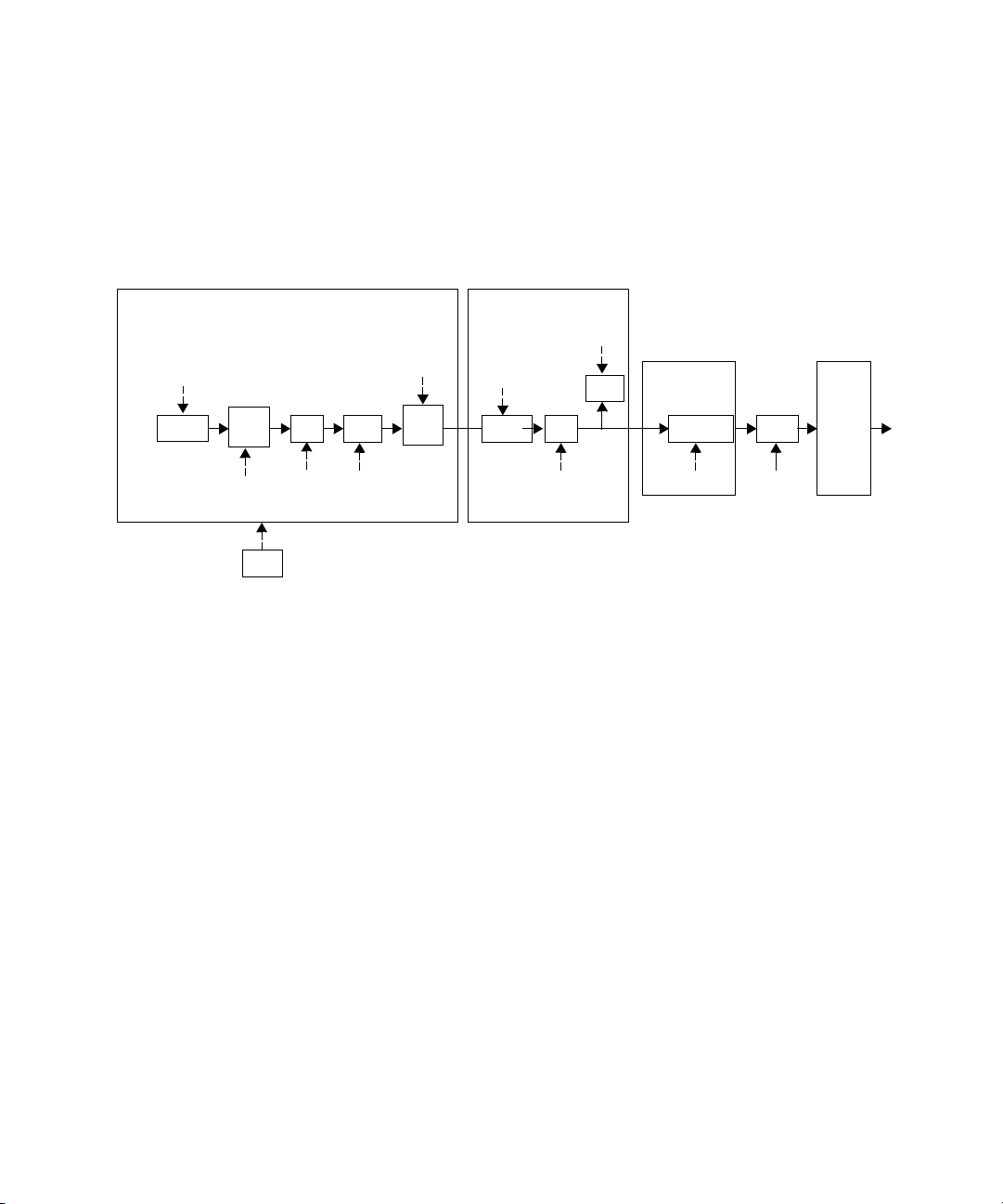
How Measurements are Calculated
SENSe[1]
Sensor
Freq.
corr.
Filter
Offset
Duty
cycle
Math
Limits
Switch
Conversion
Switch
FORMat
:FREQ
:CORR:CSET2
TRIG
:AVER :CORR:GAIN2
:CORR:DCYC
CALCulate[1]
:FEED[1]
:MATH
:LIM
UNIT[1]
:POW
MEAS?
READ?
FETC?
CONF
:MRAT
:SPE
:DET:FUNC
Figure 1-10 shows how measurements are calculated. It shows the order in which
the various U8480 Series functions are implemented in the measurement calculation.
Figure 1-10 How measurements are calculated
U8480 Series Remote Operation 1
U8480 Series Programming Guide 53
Page 54
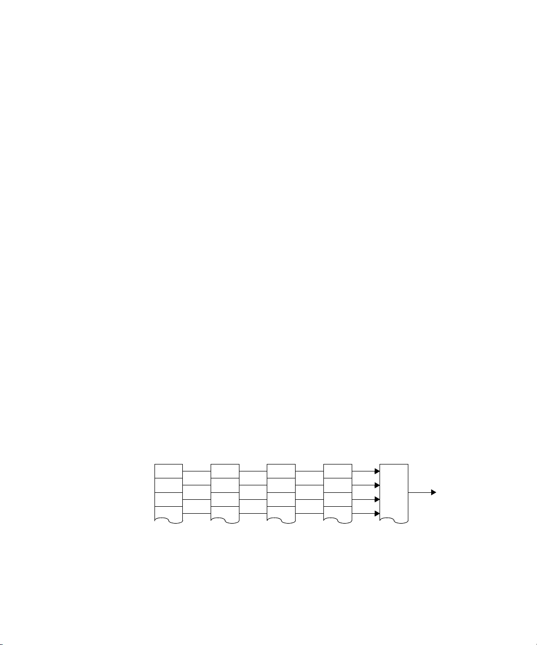
1 U8480 Series Remote Operation
0
1
2
Bit 0
Bit 1
Bit 2
Bit 3
Condition
Register
Transition
Filter
Event
Register
Enable
Register
Logical OR
Summary
Bit
Status Reporting
Status reporting is used to monitor the U8480 Series to determine when events
have occurred. Status reporting is accomplished by configuring and reading
status registers.
The U8480 Series has the following main registers:
–Status Register
– Standard Event Register
– Operation Status Register
– Questionable Status Register
– Device Status Register
There are other registers that exist “behind” the main registers, and they are
described later in this chapter.
Status and Standard Event registers are read using the IEEE-488.2 common
commands.
Operation and Questionable Status registers are read using the SCPI STATus
command subsystem.
The general status register model
The generalized status register model shown in Figure 1-11 is the building block
of the SCPI status system. This model consists of a condition register, a transition
filter, an event register, and an enable register. A set of these registers is called a
status group.
Figure 1-11 Generalized status register model
54 U8480 Series Programming Guide
Page 55

U8480 Series Remote Operation 1
When a status group is implemented in an instrument, it always contains all of the
component registers. However, there is not always a corresponding command to
read or write to every register.
Condition register
The condition register continuously monitors the hard ware and firmware status of
the U8480 Series. There is no latching or buffering for this register; it is updated in
real time. Condition registers are read-only.
Transition filter
The transition filter specifies which type of changes to the bit state in the
condition register will set corresponding bits in the event register. Transition filter
bits may be set for positive transitions (PTR), negative transitions (NTR), or both.
Positive transition will cause the corresponding bit in the event register to be set
when the condition bit changes from 0 to 1. Negative transition will cause the
corresponding bit in the event register to be set when the condition bit changes
from 1 to 0. Setting both positive and negative transitions will cause the
corresponding bit in the event register to be set whenever the condition bit
changes. Clearing both the positive and negative transition filters disables the
corresponding bit in the event register to be set. Transition filters are read-write.
They are unaffected by clear status (*CLS) or queries.
Event register
The event register latches transition events from the condition register as
specified by the transition filter. Bits in the event register are latched, and once
the bits are set, they will remain set until they are cleared by a query or clear
status (*CLS). There is no buffering; therefore, while an event bit is set,
subsequents events corresponding to that bit are ignored. Event registers are
read-only.
Enable register
The enable register specifies which bits in the event register can generate a
summary bit. The instrument logically ANDs corresponding bits in the event and
enable registers, and ORs all the resulting bits to obtain a summary bit. Summary
bits are, in turn, recorded in another register, usually the Status Byte. Enable
registers are read-write. They are not affected by clear status (*CLS) or querying
the enable registers. There is always a command to read and write to the enable
register of a particular status group.
U8480 Series Programming Guide 55
Page 56
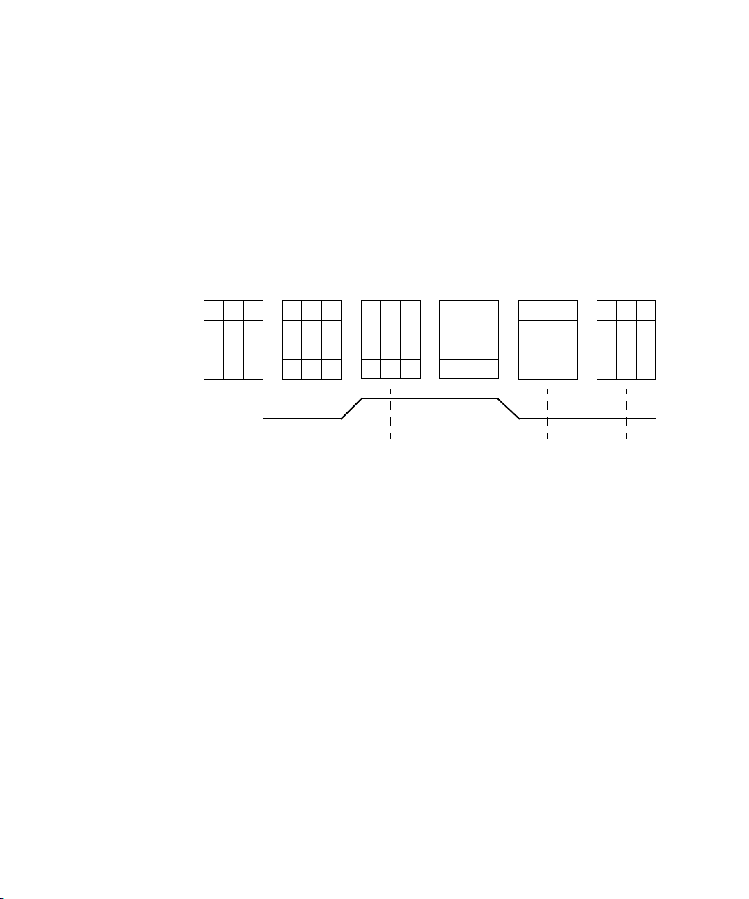
1 U8480 Series Remote Operation
00
01
110
011
0
1
00
0
0
0
0
0
1
11
011
0
1
000
1
1
0
0
1
0
1
00
01
0
01
0
1
00
0
0
0
0
00
000
000
1
0
0
0
0
0
Case A
Case B
Case C
Case D
Condition
PTR
NTR
Enable
Condition
Event
Summary Bit
Condition
Event
Summary Bit
Condition
Event
Summary Bit
Condition
Event
Summary Bit
Condition
Event
Summary Bit
1
0
T1 T2 T3
T4
T5
00
0
0
00
***
*
marks when the event register is read
An example sequence
Figure 1-12 illustrates the response of a single bit position in a typical status
group for various settings. The changing state of the condition in question is
shown at the bottom of the figure. A small binary table shows the state of the
chosen bit in each status register at selected times T1 to T5.
Figure 1-12 Typical status register bit changes
Consider Case C, where the positive transition filter is set to 1 and negative
transition filter to 0. This configures the U8480 Series to set the corresponding bit
in the event register whenever the condition bit changes from 0 to 1. The enable
register is set to 1 to enable the summary bit to be generated each time there is a
change in the event register.
At time T1, the condition bit is 0. Since there is no changes to the condition bit at
this time, no corresponding bit in the event register will be set and the summary
bit is 0.
At time T2, the condition bit changes from 0 to 1. Since the positive transition filter
56 U8480 Series Programming Guide
is set to detect condition bit changes from 0 to 1, the corresponding bit in the event
register will be set to 1. The enable register is set to 1, which means that the
summary bit will also be set to 1 whenever any bit in the event register is set to 1.
At time T3, the condition bit remains 1. The event register is cleared by a query.
Hence, the event register bit and summary bit are set to 0.
Page 57

U8480 Series Remote Operation 1
At time T4, the condition bit changes from 1 to 0. Since the positive transition
filter is set to detect condition bit changes from 0 to 1, the corresponding bit in
the event register will be set to 0, signifying no event has been logged. The
summary bit is set to 0 as no bit is set in the event register.
At time T5, the condition bit remains 0. Since there is no changes to the condition
bit at this time, no corresponding bit in the event register will be set and the
summary bit is 0.
Consider Case D, where the positive transition filter is set to 1 and negative
transition filter to 1. This configures the U8480 Series to set the corresponding bit
in the event register whenever there are changes to the condition bit. The enable
register is set to 0 to disable the summary bit to be generated.
At time T1, the condition bit is 0. Since there is no changes to the condition bit at
this time, no corresponding bit in the event register will be set and the summary
bit is 0.
At time T2, the condition bit changes from 0 to 1. Since the positive and negative
transition filters are set to detect any changes to the condition bit, the
corresponding bit in the event register will be set to 1. The enable register is set to
0, which means that the summary bit will not be set.
At time T3, the condition bit remains 1. The event register is cleared by a query.
Hence, the event register bit and summary bit are set to 0.
At time T4, the condition bit changes from 1 to 0. Since the positive and negative
transition filters are set to detect any changes to the condition bit, the
corresponding bit in the event register will be set to 1, signifying an event has
been logged. The summary bit is 0 as the enable register is set to 0.
At time T5, the condition bit remains 0. The event register is cleared by a query.
Hence, the event register bit and summary bit are set to 0.
U8480 Series Programming Guide 57
Page 58

1 U8480 Series Remote Operation
How to read registers
The condition polling method is used to access the information in the status
register groups. In this method, the U8480 Series has a passive role. It only
informs the PC that conditions have changed when the PC “asks”. When you
monitor a condition with the polling method, you must:
1 Determine which register contains the bit that monitors the condition.
2 Send the unique query that reads that register.
3 Examine the bit to see if the condition has changed.
The polling method works well if you do not need to know about the changes the
moment they occur. Detecting an immediate change in a condition using the
polling method requires your program to continuously read the registers at very
short intervals. This is not particularly efficient, and there is a possibility that an
event may be missed.
Status registers
The Status System in the U8480 Series is shown in Figure 1-13. The Operation
Status and Questionable Status groups are 16 bits wide, while the Status Byte and
Standard Event groups are 8 bits wide. In all 16-bit groups, the most significant bit
(bit 15) is not used and is always set to 0.
58 U8480 Series Programming Guide
Page 59
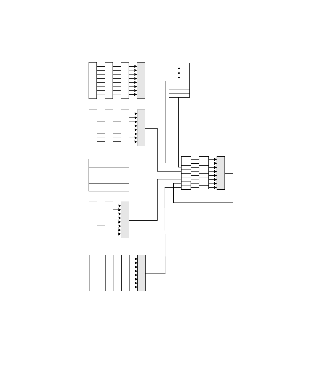
U8480 Series Remote Operation 1
Questionable Status
Logical OR
Condition Event Enable
Operation Status
Logical OR
Condition Event Enable
Standard Event
Logical OR
Event
Enable
*ESR
*ESE
Status Byte
Logical OR
*STB?
*SRE
MAV
0
1
2
QUE
ESB
RQS
OPR
MAV
0
1
2
QUE
ESB
X
OPR
Output Queue
Device Status
Logical OR
Condition Event Enable
Error/Event Queue
Figure 1-13 Status system
U8480 Series Programming Guide 59
Page 60

1 U8480 Series Remote Operation
Status byte summary register
The status byte summary register reports conditions from other status registers.
Query data waiting in the U8480 Series output buffer is immediately reported
through the “message available” bit (bit 4). Clearing an event register clears the
corresponding bits in the status byte summary register. Reading all messages in
the output buffer, including any pending queries, clears the message available bit.
Tab le 1-4 Bit definitions - Status byte register
Bit number Decimal weight Definition
0 1 Not Used (Always set to 0)
1 2 Device Status Register summary bit
One or more bits are set in the Device Status Register (bits must be “enabled” in
the enable register)
24Error/Event Queue
3 8 Questionable Status Register summary bit
One or more bits are set in the Questionable Status Register (bits must be
“enabled” in the enable register)
4 16 Data Available
Data is available in the U8480 Series output buffer
532Standard Event
One or more bits are set in the Standard Event register (bits must be “enabled” in
the enable register)
6 64 Request Service
The U8480 Series is requesting service (serial poll)
7 128 Operation Status Register summary bit
One or more bits are set in the Operation Status Register (bits must be “enabled”
in the enable register)
Particular bits in the status byte register are cleared when:
– The standard event, questionable status, operation status, and device status
are queried.
– The error or event queue becomes empty.
– The output queue becomes empty.
60 U8480 Series Programming Guide
Page 61

U8480 Series Remote Operation 1
The status byte enable register (SRE, service request enable) is cleared when you:
– cycle the U8480 Series power.
–execute a *SRE 0 command.
Using *STB? to read the status byte
The *STB? (status byte query) is similar to a serial poll except it is processed like
any other U8480 Series command. *STB? returns the same result as an IEEE-488
serial poll except that the request service bit (bit 6) is not cleared if a serial poll
has occurred. *STB? is not handled automatically by the IEEE-488 bus interface
hardware, and the query is executed only after previous commands have
completed. Using *STB? does not clear the status byte summary register.
Standard event register
The standard event register reports the following types of instrument events:
power-on detected, command and syntax errors, command execution errors,
self-test or calibration errors, query errors, or when an overlapped command
completes following an *OPC command. Any or all of these conditions can be
reported in the standard event summary bit through the enable register. You must
write a decimal value using the *ESE (event status enable) command to set the
enable register mask.
Table 1-5 Bit definitions - Standard event register
Bit number Decimal value Definition
0 1 Operation Complete
All overlapped commands following an *OPC command have been completed
1 2 Not Used (always set to 0)
24 Query Error
A query error occurred, refer to error numbers 410 to 440 in Error message list
3 8 Device-Dependent Error
A device error occurred, refer to error numbers 310 to 350 in Error message list
U8480 Series Programming Guide 61
Page 62
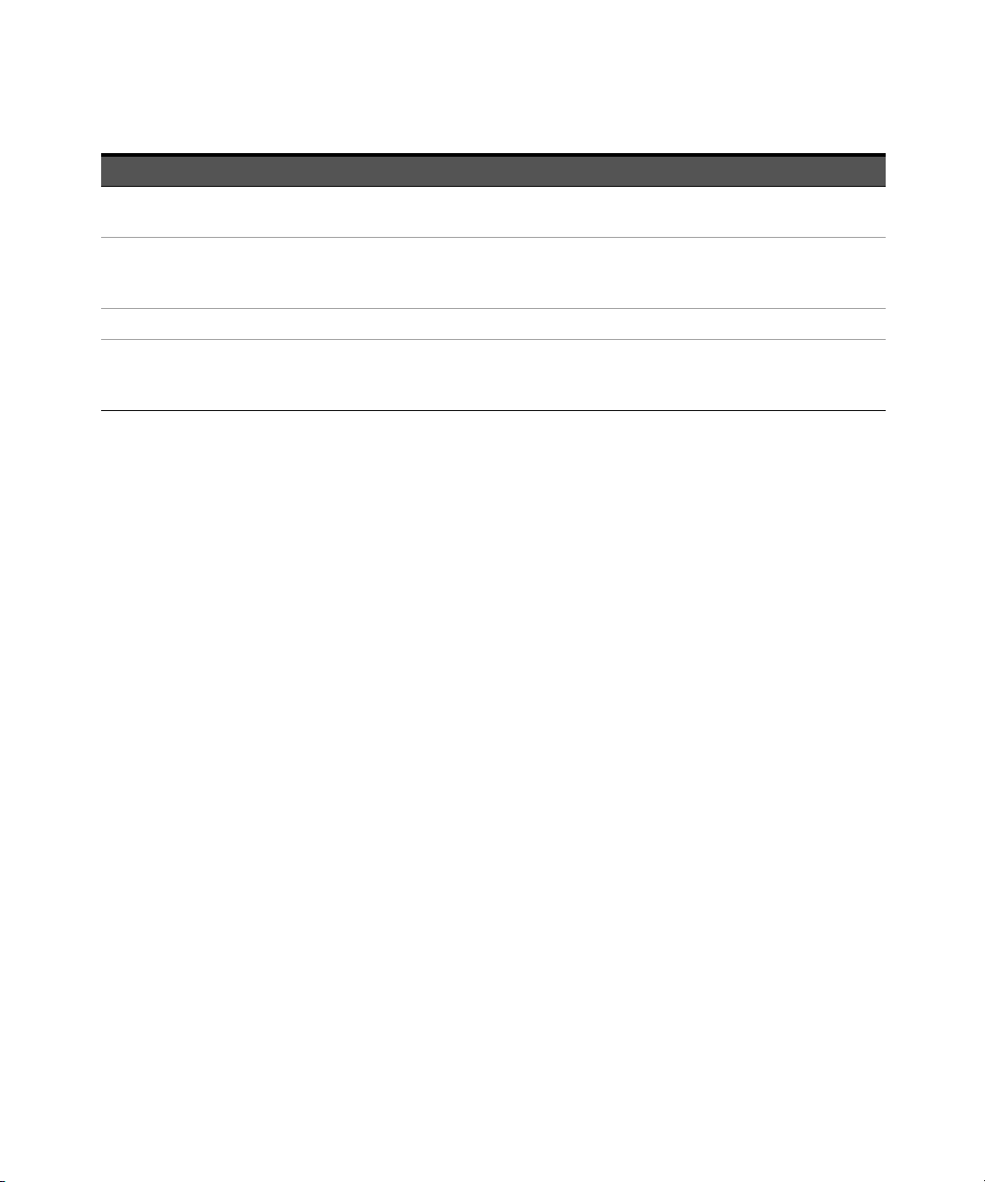
1 U8480 Series Remote Operation
Bit number Decimal value Definition
4 16 Execution Error
An execution error occurred, refer to error numbers 211 to 231 in Error message list
5 32 Command Error
A command syntax error occurred, refer to error numbers 101 to 178 in Error
message list
6 64 User Request
7 128 Power On
Power has been turned off and on since the last time the event register was read or
cleared
The standard event register is cleared when you:
–send a *CLS (clear status) command.
– query the event register using *ESR? (event status register).
The standard event enable register is cleared when you:
– cycle the U8480 Series power.
– execute an *ESE 0 command.
Questionable status register
The questionable status register provides information about the quality of the
U8480 Series measurement results. Any or all of these conditions can be reported
in the questionable data summary bit through the enable register. You must write
a value using the STATus:QUEStionable:ENABle command to set the enable
register mask.
62 U8480 Series Programming Guide
Page 63

U8480 Series Remote Operation 1
The following bits in these registers are used by the U8480 Series.
Table 1-6 Bit definitions - Questionable status registers
Bit number Decimal weight Definition
0 to 2 - Not Used
3 8 POWer Summary
4 to 7 - Not Used
8 256 CALibration Summary
9 512 Power-On Self-Test
10 to 14 - Not Used
15 - Not Used (always 0)
The condition bits are set and cleared under the following conditions:
Table 1-7 Bit change conditions for Questionable status register
Bit number Definition EVENts causing bit changes
3 POWer Summary This is a summary bit for the Questionable POWer Register
– SET:
Error –230, “Data corrupt or stale”
Error –231, “Data questionable;Input Overload”
Error –231, “Data questionable;ZERO ERROR”
– CLEARED:
When no errors are detected by the U8480 Series during a measurement
covering the causes given for it to set
U8480 Series Programming Guide 63
Page 64

1 U8480 Series Remote Operation
Bit number Definition EVENts causing bit changes
8CALibration
Summary
9 Power-On Self-Test – SET:
This is a summary bit for the Questionable CALibration Register
– SET:
These may be caused by
CALibration[1]:ZERO:AUTO ONCE or
CALibration[1]:AUTO ONCE or
CALibration[1][:ALL] or
CALibration[1][:ALL]?
Error –231, “Data questionable;ZERO ERROR”
Error –231, “Data questionable;CAL ERROR”
– CLEARED:
When any of the commands listed above succeed and no errors are placed on
the error queue
This bit is set when the power-on self-test fails
– CLEARED:
When the power-on self-test passes
Operation status register
The Operation Status group monitors conditions in the U8480 Series
measurement process.
The following bits in these registers are used by the U8480 Series:
Tab le 1-8 Bit definitions - Operation status
Bit number Decimal weight Definition
0 1 CALibrating Summary
1 to 3 - Not Used
4 16 MEASuring Summary
5 32 Waiting for TRIGger Summary
6 to 9 - Not Used
10 1024 SENSe Summary
11 2048 Lower Limit Fail Summary
12 4096 Upper Limit Fail Summary
64 U8480 Series Programming Guide
Page 65
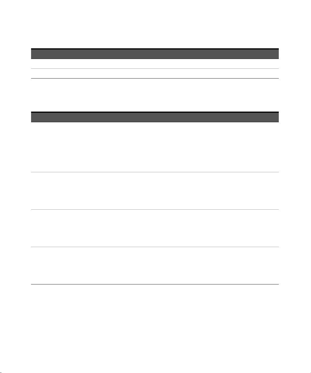
U8480 Series Remote Operation 1
Bit number Decimal weight Definition
13 to 14 - Not Used
15 - Not Used (always 0)
The condition bits are set and cleared under the following conditions:
Table 1-9 Bit change conditions for operation status
Bit number Definition EVENts causing bit changes
0 CALibrating This is a summary bit for the Operation CALibrating Register
– SET:
At the beginning of zeroing (CALibration[1]:ZERO:AUTO ONCE) or calibration
(CALibration[1]:AUTO ONCE). Also for the compound command/query
CALibration[1][:ALL]?, this bit is set when calibration begins.
– CLEARED:
At the end of zeroing or calibration
4 MEASuring This is a summary bit for the Operation MEASuring Register
– SET:
When the U8480 Series is taking a measurement
– CLEARED:
When the measurement is completed
5 Waiting for
TRIGger
10 SENSe This is a summary bit for the Operation SENSe Register
This is a summary bit for the Operation TRIGger Register
– SET:
When the U8480 Series enters the “wait-for-trigger” state
– CLEARED:
When the U8480 Series enters the “idle” state
– SET:
When the U8480 Series is reading data from the non-volatile memory
– CLEARED:
When the U8480 Series is not reading data from the non-volatile memory
U8480 Series Programming Guide 65
Page 66

1 U8480 Series Remote Operation
Bit number Definition EVENts causing bit changes
11 Lower Limit Fail This is a summary bit for the Lower Limit Fail Register
– SET:
If a measurement is made and the lower limit test fails
– CLEARED:
If a measurement is made and the lower limit test is not enabled or the test is enabled
and passes
12 Upper Limit Fail This is a summary bit for the Upper Limit Fail Register
– SET:
If a measurement is made and the upper limit test fails
– CLEARED:
If a measurement is made and the upper limit test is not enabled or the test is enabled
and passes
Device status register
The device status register set contains bits which give device-dependent
information.
The following bits in these registers are used by the U8480 Series:
Table 1-10 Bit definitions - Device status register
Bit number Decimal weight Definition
0 to 2 - Not Used
3 8 U8480 Series Error
4 to 14 - Not Used
15 - Not Used (always 0)
66 U8480 Series Programming Guide
Page 67

The condition bits are set and cleared under the following conditions:
Table 1-11 Bit change conditions for Device status
Bit number Definition EVENts causing bit changes
3 U8480 Series Error – SET:
If the U8480 Series non-volatile memory has failed or other hardware has failed
– CLEARED:
In every other condition
U8480 Series Remote Operation 1
U8480 Series Programming Guide 67
Page 68

1 U8480 Series Remote Operation
Using the Operation Complete commands
*OPC? and *OPC allow you to maintain synchronization between the PC and the
U8480 Series. *OPC? places a 1 into the U8480 Series output queue when all
pending U8480 Series commands have completed. If your program reads this
response before continuing program execution, you can ensure synchronization
between one or more sensors and the PC.
The *OPC command sets bit 0 (Operation Complete) in the Standard Event Status
Register when all pending U8480 Series operations have completed.
Procedure
1 Send a Device Clear message to clear the U8480 Series output buffer.
2 Clear the event registers with the *CLS (clear status) command.
3 Enable operation complete using the *ESE 1 command (standard event
register).
4 Send *OPC? (operation complete query) to assure synchronization.
5 Send your programming command string, and place the *OPC (operation
complete) command as the last command.
6 Send *STB? (status byte query) to poll the register. This command does not
clear the status byte summary register.
Examples
This example program uses *OPC? to determine when the U8480 Series has
finished calibrating.
CAL:AUTO ONCE
*OPC?
MEAS?
68 U8480 Series Programming Guide
Page 69

U8480 Series Remote Operation 1
Saving and Recalling U8480 Series Configurations
To reduce repeated programming, up to ten U8480 Series configurations can be
stored in the U8480 Series non-volatile memory. The error list, remote addresses,
calibration table data, and zeroing/calibration information are not stored.
How to save and recall a configuration
The U8480 Series configurations are saved and recalled with the following
commands:
*SAV <NRf>
*RCL <NRf>
The range of values for <NRf> in the above commands is 1 to 10.
U8480 Series Programming Guide 69
Page 70

1 U8480 Series Remote Operation
Using Device Clear to Halt Measurements
Device clear is an IEEE-488 low-level bus message which can be used to halt
measurements in progress. The status registers, the error queue, and all
configuration states are left unchanged when a device clear message is received.
Device clear performs the following actions:
– All measurements in progress are aborted.
– The U8480 Series returns to the trigger “idle state”.
– The U8480 Series input and output buffers are cleared.
– The U8480 Series is prepared to accept a new command string.
70 U8480 Series Programming Guide
Page 71

U8480 Series USB Thermocouple Power Sensor
Programming Guide
2 MEASurement Commands
Measurement Commands 72
CONFigure[1]? 74
CONFigure[1] Command 75
CONFigure[1][:SCALar][:POWer:AC]
[<expected_value>[,<resolution>[,<source list>]]] 76
FETCh[1]? Query 78
FETCh[1][:SCALar][:POWer:AC]?
[<expected_value>[,<resolution>[,<source list>]]] 79
FETCh[1][:SCALar][:POWer:AC]:MUNC?
[<expected_value>[,<resolution>[,<source list>]]] 81
READ[1] Query 83
READ[1][:SCALar][:POWer:AC]?
[<expected_value>[,<resolution>[,<source list>]]] 84
READ[1][:SCALar][:POWer:AC]:MUNC?
[<expected_value>[,<resolution>[,<source list>]]] 86
MEASure[1] Query 88
MEASure[1][:SCALar][:POWer:AC]?
[<expected_value>[,<resolution>[,<source list>]]] 89
MEASure[1][:SCALar][:POWer:AC]:MUNC?
[<expected_value>[,<resolution>[,<source list>]]] 91
This chapter explains how to use the MEASure group of instructions to acquire
data using a set of high-level instructions.
71
Page 72
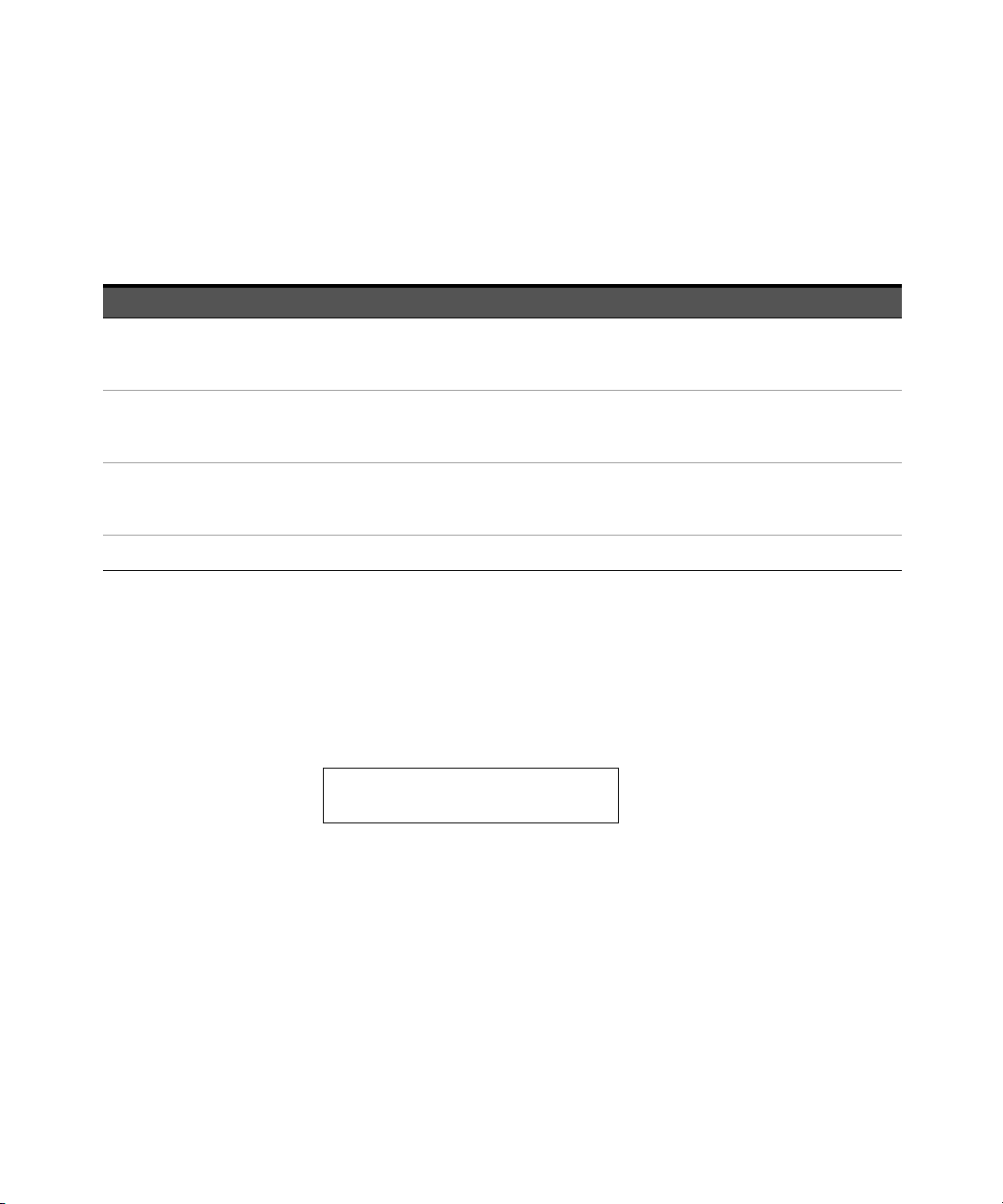
2 MEASurement Commands
CONFigure1?
current measurement
Measurement Commands
Measurement commands are high-level commands used to acquire data. They
enable you to trade interchangeability against fine control of the measurement
process.
Measurement command Description
MEASure? Provides the simplest way to program a U8480 Series for measurements. MEASure? is a
compound command which is equivalent to a CONFigure followed by a READ?. It does not
enable much flexibility or control over measurement settings.
CONFigure Used to change the U8480 Series configuration values. CONFigure must then be followed by
another command which takes the measurement, for example, INITiate? followed by
FETCh?
READ? Takes a measurement using parameters previously set up using either CONFigure or
lower-level commands. READ? is equivalent to an INITiate (which performs the data
acquisition) and a FETCh?
FETCh?
[a] INITiate is described in Chapter 12, “TRIGger Subsystem” on page 297.
Retrieves measurements taken by INITiate
[a]
.
CONFigure, FETCh?, READ?, and MEASure? all have a numeric suffix which refers to
a specific measurement window. The U8480 Series does not have the
measurement window feature, so this suffix is always 1. Figure 2-1 shows an
example of the configuration returned measurement result.
Figure 2-1 Measurement display CALCulate block channel
72 U8480 Series Programming Guide
Page 73

Optional parameters
CONFigure, FETCh?, READ?, and MEASure? have the following three optional
parameters:
– An expected power value
–A resolution
– A source list
Refer to “Auto-Averaging Settings” on page 374 to configure the correct
parameters for expected power and resolution.
Expected power value
The <expected_value> parameter sets the expected power level of the
measurement.
Resolution
The <resolution> parameter sets the resolution of the measurement. This
parameter does not affect the resolution of the returned data, but it does affect
the auto-averaging setting.
MEASurement Commands 2
Source list
The <source list> parameter is used to define the measurement channel.
U8480 Series Programming Guide 73
Page 74

2 MEASurement Commands
?
CONF
1
CONFigure[1]?
This query returns the present configuration of the measurement.
Syntax
The returned string depends on the setting of the CALCulate:MATH commands.
The configuration is returned as a quoted string in the following format:
<function> <expected_value>,<resolution>,<source list>”
<expected_value> returns the expected value sent by the last CONFigure
command or +20 dBm by default.
Example
CONF? Queries the measurement configuration.
Reset condition
On reset:
– The command function is set to :POWer:AC.
– The expected power level is set to +20 dBm.
– The resolution is set to 3.
– The source list on the U8480 Series is set to (@1).
74 U8480 Series Programming Guide
Page 75

MEASurement Commands 2
CONFigure[1] Command
The CONFigure command is used to set:
– the expected measurement power level.
– the measurement resolution.
The CONFigure command does not make the power measurement after setting
the configuration. Use READ?, or alternatively use INITiate followed by a FETCh?,
to make the measurement.
The CONFigure command also applies the following defaults to the
measurement(s) which are specified in the <source list> parameter:
Default settings Description
INITiate[1]:CONTinuous OFF Sets the U8480 Series to make one trigger cycle when
INITiate is sent
TRIGger[1]:SOURce IMMediate When TRIG:SOUR is set to BUS or HOLD, sets the U8480
Series to make the measurement immediately once a trigger
is received
TRIGger[1]:DELay:AUTO ON Enables automatic delay before making the measurement
[SENSe[1]:]AVERage:COUNt:AUTO ON Enables automatic filter length selection
[SENSe[1]:]AVERage:STATe ON Enables averaging
U8480 Series Programming Guide 75
Page 76
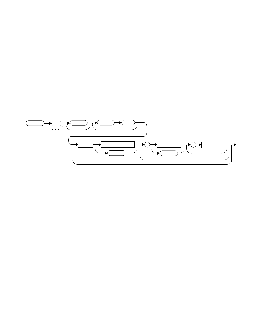
2 MEASurement Commands
Space
expected_value
DEF
resolution
,
:POW
:AC
:SCAL
DEF
source list
,
CONF
1
CONFigure[1][:SCALar][:POWer:AC] [<expected_value>[,<resolution>[,<source list>]]]
This command is used to set:
– the expected measurement power level.
– the measurement resolution.
Refer to “Auto-Averaging Settings” on page 374 to configure the correct
parameters for the expected power and resolution.
Syntax
76 U8480 Series Programming Guide
Page 77

MEASurement Commands 2
Parameters
Refer to “Optional parameters” on page 73 for additional details on the
parameters in this command.
Item Description/Default Range of values
expected_value A numeric value for the expected power level. The
units of measurement are dBm and W. The default
units are defined by UNIT:POWer
resolution A numeric value for the resolution. If unspecified, the current
resolution setting is used.
sensor-dependent
[a]
DEF
[b]
1 to 4
1.0, 0.1, 0.01, 0.001
[a]
DEF
source list The measurement channel which the command is
implemented on. The U8480 Series supports only one
channel. Therefore, the only valid value is (@1).
[a] The mnemonic DEF means DEFault. This is not equivalent to the DEFault parameter used in the command subsystems. The parameters must
be entered in the specified order. If parameters are omitted, they default from the right. The parameter DEFault is used as a placeholder.
Specifying DEF leaves the parameter value unchanged.
[b] When the measurement result is linear, this parameter represents the number of significant digits. When the measurement result is
logarithmic, 1 to 4 represents 1, 0.1, 0.01, and 0.001 respectively.
(@1)
Example
CONF DEF,2,(@1) This command configures the measurement
to measure power using the current range
and a resolution setting of 2.
U8480 Series Programming Guide 77
Page 78

2 MEASurement Commands
NOTE
FETCh[1]? Query
The FETCh? query calculates the measurement and sends the result to the PC.
The result format is set by FORMat[:READing][:DATA]. Refer to Chapter 5,
“FORMat Subsystem,” on page 125 for further information.
The query returns a measurement result when it is valid. The measurement result
is invalid under the following conditions:
– when *RST is executed.
– whenever a measurement is initiated.
– when any SENSe parameter, such as frequency, is changed.
If the data is invalid, the FETCh? query is not completed until all data becomes
valid. The exceptions to this are, if the U8480 Series is in the idle state and the
data is invalid, or the U8480 Series has been reconfigured as defined above and
no new measurement has been initiated. In such cases, the FETCh? routine
generates the error –230, “Data corrupt or stale” and no result is returned. A
common cause for this error is receiving a FETCh?
value and resolution parameters are not the same as those that were used to
collect the data, error –221, “Settings conflict” occurs.
after a *RST. If the expected
When TRIGger[1]:SOURce is EXT and a new acquisition has been initiated (using
the INITiate command for example), FETCh? waits until the trigger takes place
before executing. If trigger conditions are not satisfied — when the trigger level
differs greatly from the signal level for example — this can give the impression
that the U8480 Series has hung.
To unlock the U8480 Series and adjust trigger settings, a Device Clear command
must be performed.
78 U8480 Series Programming Guide
Page 79
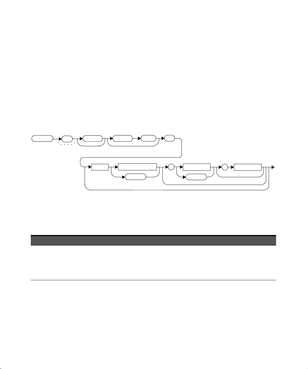
MEASurement Commands 2
:POW
:AC
?
:SCAL
Space
expected_value
DEF
resolution
,
DEF
source list
,
FETC
1
FETCh[1][:SCALar][:POWer:AC]? [<expected_value>[,<resolution>[,<source list>]]]
This command sets the measurement function, recalculates the measurement,
and places the result on the bus. The result is a power-based measurement and is
expressed in the units defined by UNIT[1]:POWer.
Refer to “Auto-Averaging Settings” on page 374 to configure the correct
parameters for the expected power and resolution.
Syntax
Parameters
Refer to “Optional parameters” on page 73 for additional details on the
parameters in this command.
Item Description/Default Range of values
expected_value The expected power level parameter can be set to DEF or a
numeric value. If a value is entered, it should correspond to
that set by CONFigure otherwise an error occurs. The units of
measurement are dBm and W. The default units are defined by
UNIT:POWer.
U8480 Series Programming Guide 79
sensor-dependent
[a]
DEF
Page 80

2 MEASurement Commands
Item Description/Default Range of values
resolution A numeric value for the resolution. If it is unspecified, the
current resolution setting is used. If a value is entered, it
should correspond to the current resolution setting otherwise
an error occurs.
[b]
1 to 4
1.0, 0.1, 0.01, 0.001
[a]
DEF
source list The measurement channel which the command is
implemented on. The U8480 Series supports only one
channel. Therefore, the only valid value is (@1).
[a] The mnemonic DEF means DEFault. This is not equivalent to the DEFault parameter used in the command subsystems. The parameters must
be entered in the specified order. If parameters are omitted, they default from the right. The parameter DEFault is used as a placeholder.
Specifying DEF leaves the parameter value unchanged.
[b] When the measurement result is linear, this parameter represents the number of significant digits. When the measurement result is
logarithmic, 1 to 4 represents 1, 0.1, 0.01, and 0.001 respectively.
(@1)
Example
FETC? Queries the measurement result.
Error messages
– If the last measurement is not valid, error –230, “Data corrupt or stale” occurs.
A measurement is valid after it has been initiated. It becomes invalid when
either a reset occurs or any measurement parameter, for example frequency, is
changed.
– If the expected_value and resolution parameters are not the same as the
current expected value and resolution settings on the measurement, error
–221, “Settings conflict” occurs.
80 U8480 Series Programming Guide
Page 81
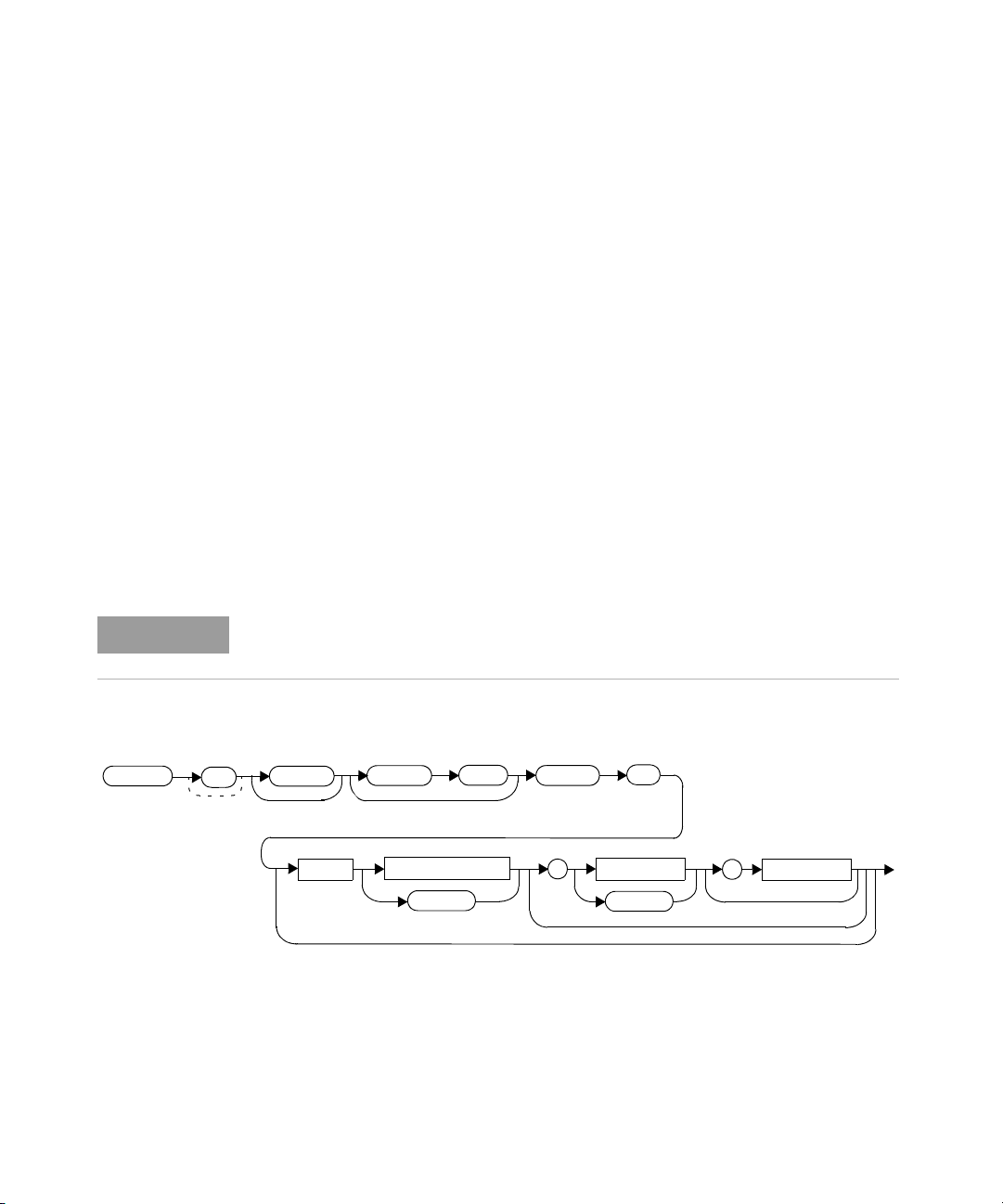
MEASurement Commands 2
NOTE
:POW
:AC
?
:SCAL
Space
expected_value
DEF
resolution
,
DEF
source list
,
FETC
1
:MUNC
FETCh[1][:SCALar][:POWer:AC]:MUNC? [<expected_value>[,<resolution>[,<source list>]]]
This command sets the measurement function, recalculates the measurement and
the corresponding measurement uncertainty, and places the result on the bus.
The result is a power-based measurement and is expressed in the units defined by
UNIT[1]:POWer.
When “UNIT:POW W” is set, the parameters returned will be:
–measured power in Watts
– +measurement uncertainty value in %
– –measurement uncertainty value in %
When “UNIT:POW DBM” is set, the parameters returned will be:
–measured power in dBm
– +measurement uncertainty value in dB
– –measurement uncertainty value in dB.
This query is only supported for TRIG:COUNT of 1. It is not supported for power
and frequency sweep modes.
Syntax
U8480 Series Programming Guide 81
Page 82

2 MEASurement Commands
Parameters
Refer to “Optional parameters” on page 73 for additional details on the
parameters in this command.
Item Description/Default Range of values
expected_value The expected power level parameter can be set to DEF or a
numeric value. If a value is entered, it should correspond to
that set by CONFigure otherwise an error occurs. The units of
measurement are dBm and W. The default units are defined by
UNIT:POWer.
resolution A numeric value for the resolution. If it is unspecified, the
current resolution setting is used. If a value is entered, it
should correspond to the current resolution setting otherwise
an error occurs.
source list The measurement channel which the command is
implemented on. The U8480 Series supports only one
channel. Therefore, the only valid value is (@1).
[a] The mnemonic DEF means DEFault. This is not equivalent to the DEFault parameter used in the command subsystems. The parameters must
be entered in the specified order. If parameters are omitted, they default from the right. The parameter DEFault is used as a placeholder.
Specifying DEF leaves the parameter value unchanged.
[b] When the measurement result is linear, this parameter represents the number of significant digits. When the measurement result is
logarithmic, 1 to 4 represents 1, 0.1, 0.01, and 0.001 respectively.
sensor-dependent
[a]
DEF
[b]
1 to 4
1.0, 0.1, 0.01, 0.001
[a]
DEF
(@1)
Error messages
– If this query is sent, and TRIG:COUNT > 1, error –221, “Settings conflict”
occurs.
82 U8480 Series Programming Guide
Page 83

READ[1] Query
The READ? query is most commonly used with the CONFigure command to cause a
new power measurement to be taken and the result returned to the output buffer.
The result format is set by FORMat[:READing][:DATA]. Refer to Chapter 5,
“FORMat Subsystem” on page 125 for further information.
The READ? query is equivalent to:
MEASurement Commands 2
INITiate
FETCh?
U8480 Series Programming Guide 83
Page 84
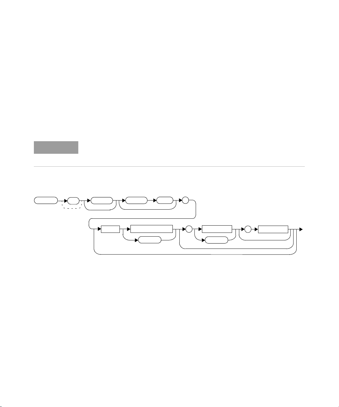
2 MEASurement Commands
NOTE
:POW
:AC
:SCAL
?
Space
expected_value
DEF
resolution
,
DEF
source list
,
READ
1
READ[1][:SCALar][:POWer:AC]? [<expected_value>[,<resolution>[,<source list>]]]
This query sets the measurement function, aborts then initiates the measurement,
calculates the measurement result, and places the result on the bus. The result is
a power-based measurement and is expressed in the units defined by
UNIT[1]:POWer.
Refer to “Auto-Averaging Settings” on page 374 to configure the correct
parameters for expected power and resolution.
INITiate[1]:CONTinuous must be set to OFF, otherwise error –213, “INIT
ignored” occurs. If TRIGger[1]:SOURce is set to BUS, error –214, “Trigger
deadlock” occurs.
Syntax
84 U8480 Series Programming Guide
Page 85

MEASurement Commands 2
Parameters
Refer to “Optional parameters” on page 73 for additional details on the
parameters in this query.
Item Description/Default Range of values
expected_value
(for the expected power
level)
resolution A numeric value for the resolution. If it is unspecified, the
source list The measurement channel which the command is
[a] The mnemonic DEF means DEFault. This is not equivalent to the DEFault parameter used in the command sub-systems. The parameters must
be entered in the specified order. If parameters are omitted, they default from the right. The parameter DEFault is used as a placeholder.
Specifying DEF leaves the parameter value unchanged.
[b] When the measurement result is linear, this parameter represents the number of significant digits. When the measurement result is
logarithmic, 1 to 4 represents 1, 0.1, 0.01, and 0.001 respectively.
The expected power level parameter can be set to
DEF or a numeric value. If a value is entered, it should
correspond to that set by CONFigure otherwise an
error occurs.
current resolution setting is used. If a value is entered, it
should correspond to the current resolution setting otherwise
an error occurs.
implemented on. The U8480 Series supports only one
channel. Therefore, the only valid value is (@1).
sensor-dependent
[a]
DEF
[b]
1 to 4
1.0, 0.1, 0.01, 0.001
[a]
DEF
(@1)
Example
READ? Queries the measurement.
Error messages
– INITiate[1]:CONTinuous must be set to OFF, otherwise error –213, “Init
ignored” occurs.
–If TRIGger[1]:SOURce is set to BUS or HOLD, error –214, “Trigger deadlock”
occurs.
– If the expected value and resolution parameters are not the same as the
current expected value and resolution settings on the measurement, error
–221, “Settings conflict” occurs.
U8480 Series Programming Guide 85
Page 86
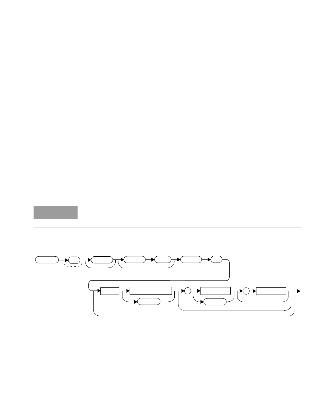
2 MEASurement Commands
NOTE
:POW
:AC
?
:SCAL
Space
expected_value
DEF
resolution
,
DEF
source list
,
READ
1
:MUNC
READ[1][:SCALar][:POWer:AC]:MUNC? [<expected_value>[,<resolution>[,<source list>]]]
This command sets the measurement function, aborts then initiates the
measurement and the corresponding measurement uncertainty, and places the
result on the bus. The result is a power-based measurement and is expressed in
the units defined by UNIT[1]:POWer.
When “UNIT:POW W” is set, the parameters returned will be:
– measured power in Watts
– +measurement uncertainty value in %
– –measurement uncertainty value in %
When “UNIT:POW DBM” is set, the parameters returned will be:
– measured power in dBm
– +measurement uncertainty value in dB
– –measurement uncertainty value in dB.
This query is only supported for TRIG:COUNT of 1. It is not supported for power
and frequency sweep modes.
Syntax
86 U8480 Series Programming Guide
Page 87

MEASurement Commands 2
Parameters
Refer to “Optional parameters” on page 73 for additional details on the
parameters in this query.
Item Description/Defaul t Range of values
expected_value
(for the expected power
level)
resolution A numeric value for the resolution. If it is unspecified, the
source list The measurement channel which the command is
[a] The mnemonic DEF means DEFault. This is not equivalent to the DEFault parameter used in the command sub-systems. The parameters must
be entered in the specified order. If parameters are omitted, they default from the right. The parameter DEFault is used as a placeholder.
Specifying DEF leaves the parameter value unchanged.
[b] When the measurement result is linear, this parameter represents the number of significant digits. When the measurement result is
logarithmic, 1 to 4 represents 1, 0.1, 0.01, and 0.001 respectively.
The expected power level parameter can be set to DEF or a
numeric value. If a value is entered, it should correspond to
that set by CONFigure
current resolution setting is used. If a value is entered, it
should correspond to the current resolution setting
otherwise an error occurs.
implemented on. The U8480 Series supports only one
channel. Therefore, the only valid value is (@1).
otherwise an error occurs.
sensor-dependent
[a]
DEF
[b]
1 to 4
1.0, 0.1, 0.01, 0.001
[a]
DEF
(@1)
Error messages
– INITiate[1]:CONTinuous must be set to OFF, otherwise error –213, “Init
ignored” occurs.
–If TRIGger[1]:SOURce is set to BUS or HOLD, error –214, “Trigger deadlock”
occurs.
– If the expected value and resolution parameters are not the same as the
current expected value and resolution settings on the measurement, error
–221, “Settings conflict” occurs.
– If this query is sent, and TRIG:COUNT > 1, error –221, “Settings conflict” occurs.
U8480 Series Programming Guide 87
Page 88

2 MEASurement Commands
MEASure[1] Query
The MEASure? query configures the U8480 Series to perform a power measurement
with the given measurement function, range, and resolution, and then make the
measurement. The format of the result is set by FORMat[:READing][:DATA]. Refer
to Chapter 5, “FORMat Subsystem” on page 125 for further information.
The MEASure? compound command is equivalent to:
CONFigure
READ?
88 U8480 Series Programming Guide
Page 89
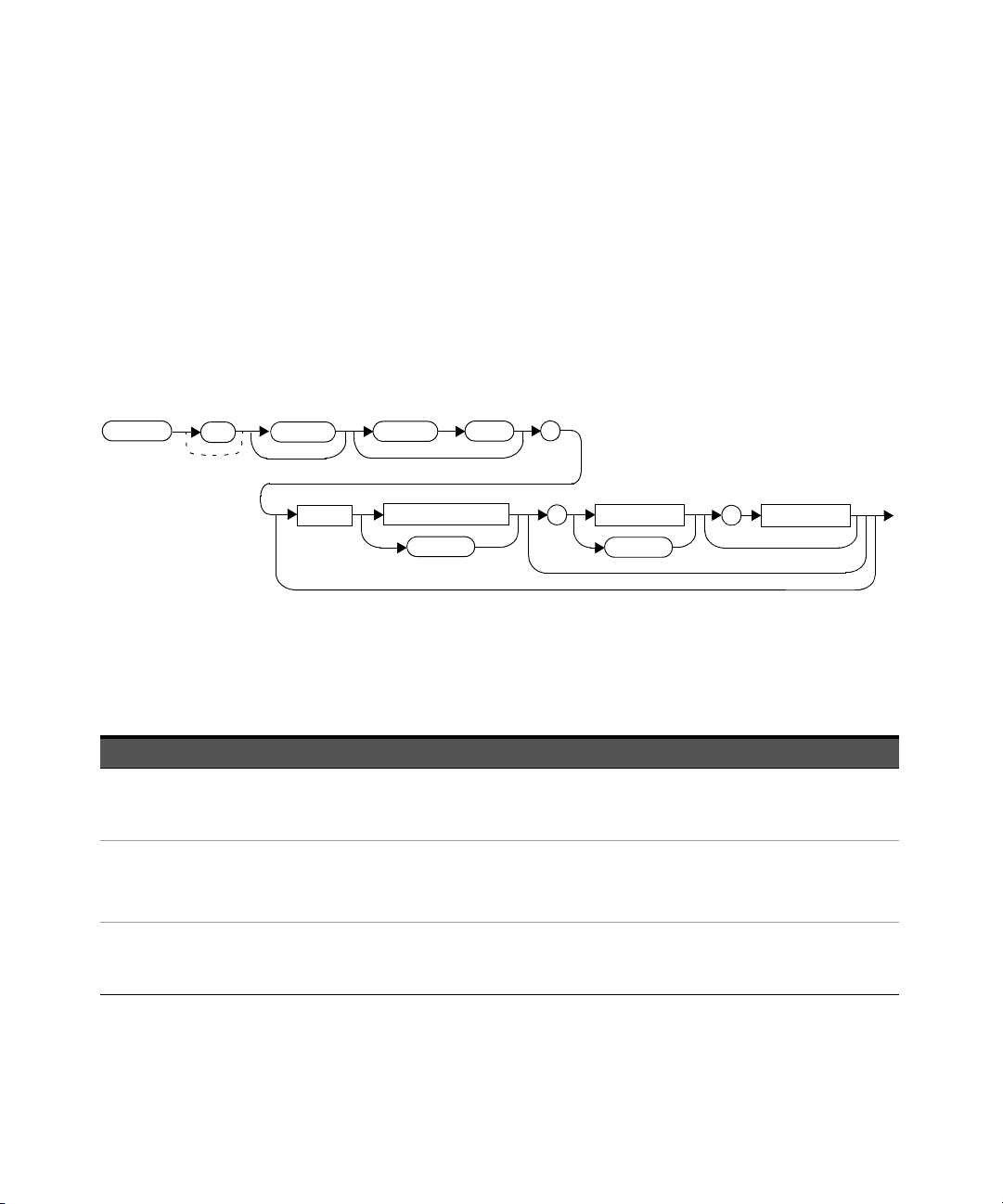
MEASurement Commands 2
:POW
:AC
:SCAL
?
Space
expected_value
DEF
resolution
,
DEF
source list
,
MEAS
1
MEASure[1][:SCALar][:POWer:AC]? [<expected_value>[,<resolution>[,<source list>]]]
This query aborts any measurement in progress, configures the U8480 Series,
calculates the measurement result, and places the result on the bus.
Refer to “Auto-Averaging Settings” on page 374 to configure the correct
parameters for the expected power and resolution.
Syntax
Parameters
Refer to “Optional parameters” on page 73 for additional details on the
parameters in this query.
Item Description/Default Range of values
expected_value
(for the expected power
level)
resolution A numeric value for the resolution. If unspecified, the current
source list The measurement channel which the command is
U8480 Series Programming Guide 89
A numeric value for the expected power level. The units of
measurement are dBm and W. The default units are defined
by UNIT:POWer.
resolution setting is used.
implemented on. The U8480 Series supports only one
channel. Therefore, the only valid value is (@1).
sensor-dependent
[a]
DEF
[b]
1 to 4
1.0, 0.1, 0.01, 0.001
[a]
DEF
(@1)
Page 90

2 MEASurement Commands
[a] The mnemonic DEF means DEFault. This is not equivalent to the DEFault parameter used in the command subsystems. The parameters must
be entered in the specified order. If parameters are omitted, they default from the right. The parameter DEFault is used as a placeholder.
Specifying DEF leaves the parameter value unchanged.
[b] When the measurement result is linear, this parameter represents the number of significant digits. When the measurement result is
logarithmic, 1 to 4 represents 1, 0.1, 0.01, and 0.001 respectively.
Example
MEAS? -10DBM,1,(@1) Queries the measurement using an expected
power level of –10 dBm and a resolution
setting of 1.
90 U8480 Series Programming Guide
Page 91
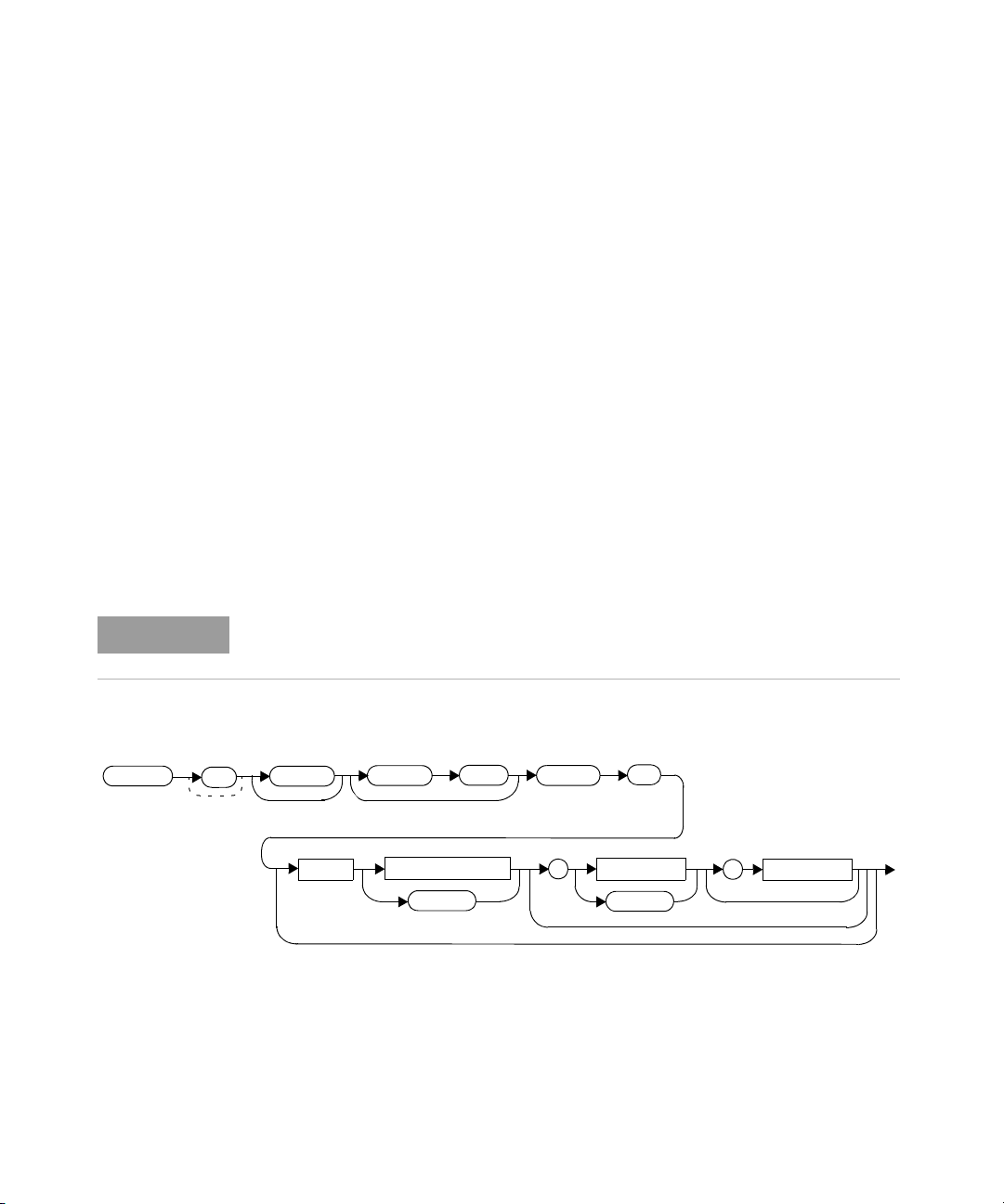
MEASurement Commands 2
NOTE
:POW
:AC
?
:SCAL
Space
expected_value
DEF
resolution
,
DEF
source list
,
MEAS
1
:MUNC
MEASure[1][:SCALar][:POWer:AC]:MUNC? [<expected_value>[,<resolution>[,<source list>]]]
This command aborts any measurement in progress, configures the U8480 Series,
calculates the measurement result and the corresponding measurement
uncertainty, and places the result on the bus. The result is a power-based
measurement and is expressed in the units defined by UNIT[1]:POWer.
When “UNIT:POW W” is set, the parameters returned will be:
–measured power in Watts
– +measurement uncertainty value in %
– –measurement uncertainty value in %
–When “UNIT:POW DBM” is set, the parameters returned will be:
–measured power in dBm
– +measurement uncertainty value in dB
– –measurement uncertainty value in dB.
This query is only supported for TRIG:COUNT of 1. It is not supported for power
and frequency sweep modes.
Syntax
U8480 Series Programming Guide 91
Page 92

2 MEASurement Commands
Parameters
Refer to “Optional parameters” on page 73 for additional details on the
parameters in this query.
Item Description/Defaul t Range of values
expected_value
(for the expected power
level)
resolution A numeric value for the resolution. If unspecified, the current
source list The measurement channel which the command is
[a] The mnemonic DEF means DEFault. This is not equivalent to the DEFault parameter used in the command subsystems. The parameters must
be entered in the specified order. If parameters are omitted, they default from the right. The parameter DEFault is used as a placeholder.
Specifying DEF leaves the parameter value unchanged.
[b] When the measurement result is linear, this parameter represents the number of significant digits. When the measurement result is
logarithmic, 1 to 4 represents 1, 0.1, 0.01, and 0.001 respectively.
A numeric value for the expected power level. The units of
measurement are dBm and W. The default units are defined
by UNIT:POWer.
resolution setting is used.
implemented on. The U8480 Series supports only one
channel. Therefore, the only valid value is (@1).
sensor-dependent
[a]
DEF
[b]
1 to 4
1.0, 0.1, 0.01, 0.001
[a]
DEF
(@1)
Error messages
– If this query is sent, and TRIG:COUNT > 1, error –221, “Settings conflict”
occurs.
92 U8480 Series Programming Guide
Page 93

U8480 Series USB Thermocouple Power Sensor
Programming Guide
3 CALCulate Subsystem
CALCulate Command Subsystem 94
CALCulate[1]:FEED[1] <“string”> 95
CALCulate[1]:LIMit Commands 97
CALCulate[1]:LIMit:CLEar:AUTO <boolean>|ONCE 98
CALCulate[1]:LIMit:CLEar[:IMMediate] 100
CALCulate[1]:LIMit:FAIL? 101
CALCulate[1]:LIMit:FCOunt? 102
CALCulate[1]:LIMit:LOWer[:DATA] <numeric_value> 104
CALCulate[1]:LIMit:UPPer[:DATA] <numeric_value> 106
CALCulate[1]:LIMit:STATe <boolean> 108
CALCulate[1]:MATH Commands 110
CALCulate[1]:MATH[:EXPRession] <“string”> 111
CALCulate[1]:MATH[:EXPRession]:CATalog? 113
This chapter explains how the CALCulate command subsystem is used to
perform post-acquisition data processing.
93
Page 94
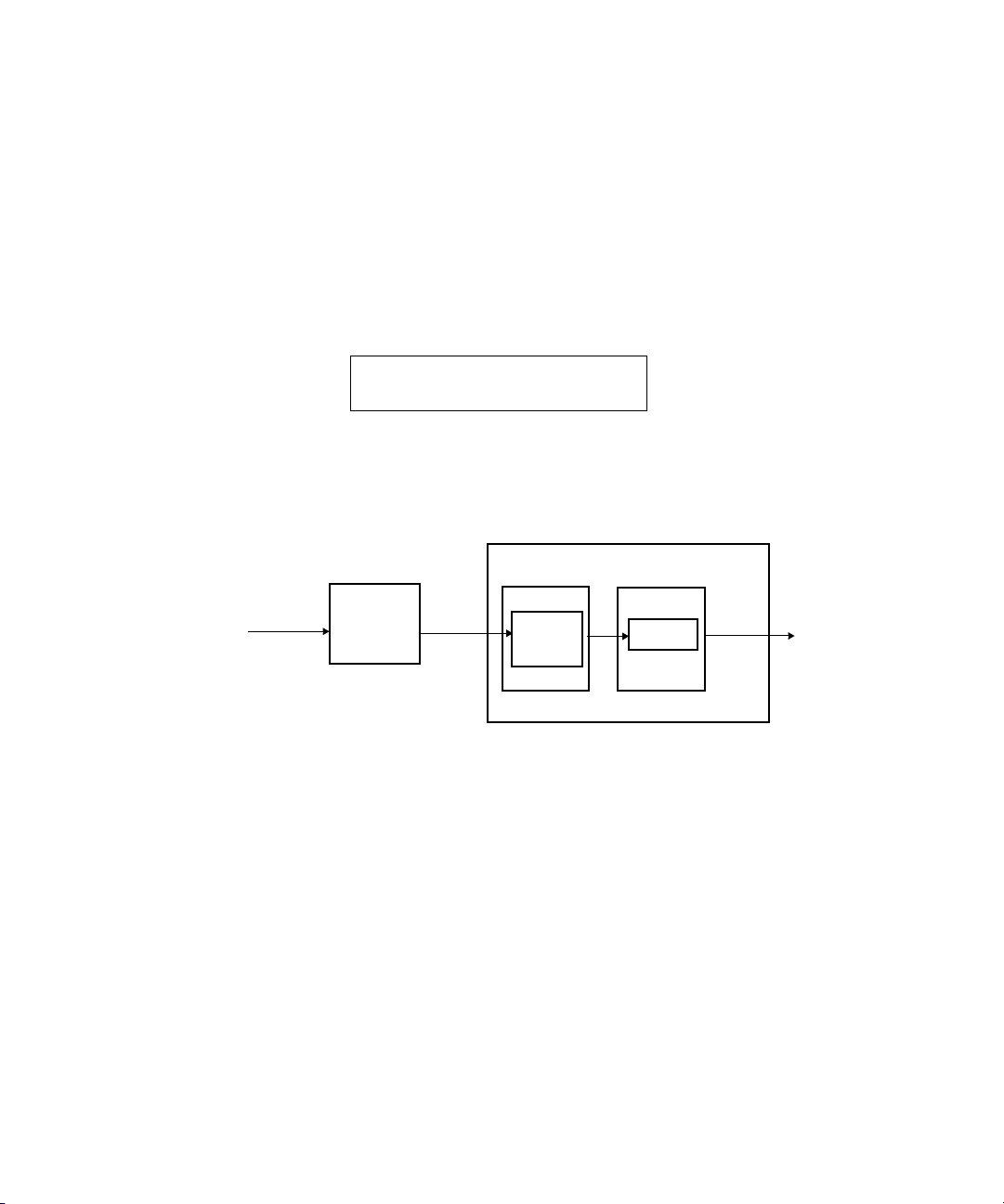
3 CALCulate Subsystem
CALC1
current measurement
“A”
:MATH
CALCulate Block
SENSe[1]:
Input from
SENSe[1]
block
FEED1
:FEED
Avg
CALCulate Command Subsystem
The CALCulate command subsystem performs post-acquisition data processing.
Functions in the SENSe command subsystem are related to data acquisition, while
the CALCulate command subsystem operates on the data acquired by a SENSe
function.
There is an independent CALCulate block in the U8480 Series, as shown below.
Figure 3-1 Measurement display CALCulate block channel
Figure 3-2 details where the commands are applied within the CALCulate block.
Figure 3-2 CALCulate block
94 U8480 Series Programming Guide
Page 95
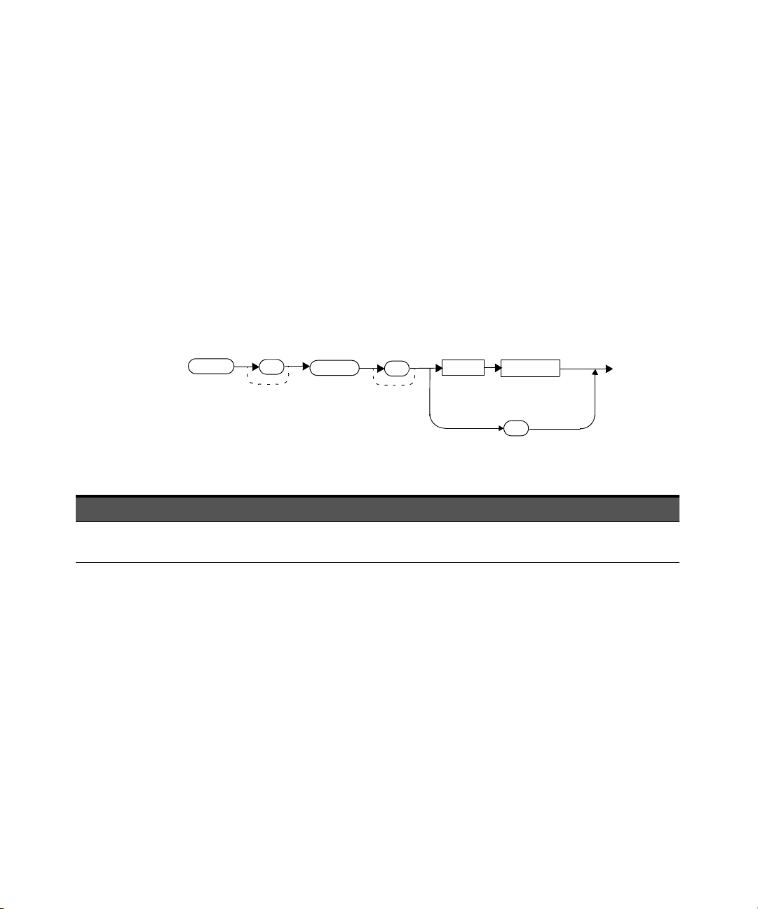
CALCulate[1]:FEED[1] <“string”>
Space
?
“string”
:FEED
1
CALC
1
This command sets the input measurement mode to be fed to the specified input
on the CALC block. It is applied to the measurement after the
CALCulate[1]:MATH[:EXPRession] command has been used to specify which
measurement the feed is taken from.
Under certain circumstances, the measurement mode is changed by the
CALCulate[1]:MATH[:EXPRession] command. Refer to
“CALCulate[1]:MATH[:EXPRession] <“string”>” on page 111 for further
information.
Syntax
CALCulate Subsystem 3
Parameters
Item Description Range of values
string The input measurement type to be fed to the specific input on the CALC block
is AVER (average).
“POW:AVER”
Example
CALC:FEED “POW:AVER” This command selects the input for FEED of
the CALC block to be average power. The
measurement from which the feed is taken is
determined by CALC:MATH:EXPR.
U8480 Series Programming Guide 95
Page 96

3 CALCulate Subsystem
Reset condition
On reset, the feed is set to POW:AVER.
Query
CALCulate[1]:FEED[1]?
The query returns the current value of the string.
Query example
CALC:FEED? Queries the current setting of the CALC block
Error message
If the command parameter is not “POW:AVER”, error –224, “Illegal parameter
value” occurs.
on FEED.
96 U8480 Series Programming Guide
Page 97

CALCulate[1]:LIMit Commands
These commands set the measurement limits which enable you to:
– set upper-level and lower-level limits
– query if there has been a failure
– count the number of failures
– clear the counter
The following commands or queries are detailed in this section:
CALCulate[1]:LIMit:CLEar:AUTo <boolean>|ONCE
CALCulate[1]:LIMit:CLEar[IMMediate]
CALCulate[1]:LIMit:FAIL?
CALCulate[1]:LIMit:FCOunt?
CALCulate[1]:LIMit:LOWer[:DATA] <numeric_value>
CALCulate[1]:LIMit:UPPer[:DATA] <numeric_value>
CALCulate[1]:LIMit:STATe <boolean>
CALCulate Subsystem 3
U8480 Series Programming Guide 97
Page 98
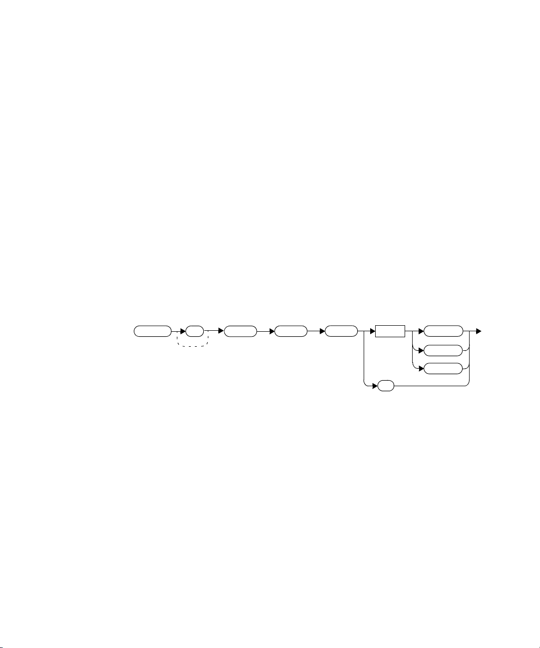
3 CALCulate Subsystem
0|OFF
1|ON
Space
?
:LIM
:CLE
:AUTO
ONCE
CALC
1
CALCulate[1]:LIMit:CLEar:AUTO <boolean>|ONCE
This command controls when the FCO (fail counter) is cleared of any limit failure.
The FCO is used to determine the results returned by the
CALCulate[1]:LIMit:FAIL? query.
–If ON is specified, the FCO is set to 0 each time a measurement is:
– initiated using INITiate[1][:IMMediate]
– initiated using INITiate[1]:CONTinuous ON
–measured using MEASure?
–read using READ?
–If OFF is specified, the FCO is not cleared by the above commands or queries.
–If ONCE is specified, the FCO is cleared only after the first initialization, and then
starts accumulating any limit failures.
Syntax
Example
CALC:LIM:CLE:AUTO 1 This command switches on automatic
clearing of the FCO.
98 U8480 Series Programming Guide
Page 99

Reset condition
On reset, CALCulate[1]:LIMit:CLEar:AUTO is set to ON.
Query
CALCulate[1]:LIMit:CLEar:AUTO?
The query enters a 1 or 0 into the output buffer indicating whether limit failures
are cleared automatically when a new measurement is initiated.
– 1 is entered into the output buffer when limit failures are cleared automatically
when a new measurement is initiated.
– 0 is entered into the output buffer when limit failures are not cleared
automatically when a new measurement is initiated.
In the case where limit failures are cleared once, when a query occurs, 1 is entered
into the output buffer if no measurement is initiated. If a measurement is initiated,
then 0 is entered.
Query example
CALCulate Subsystem 3
CALC:LIM:CLE:AUTO? Queries when the fail counter is cleared.
U8480 Series Programming Guide 99
Page 100
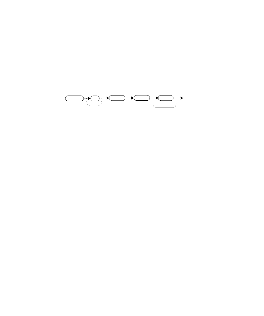
3 CALCulate Subsystem
:LIM
:CLE
:IMM
CALC
1
CALCulate[1]:LIMit:CLEar[:IMMediate]
This command immediately clears the FCO (fail counter) of any limit failure. The
FCO is used to determine the results returned by the
CALCulate[1]:LIMit:FAIL? query.
Syntax
Example
CALC:LIM:CLE:IMM This command clears the FCO.
100 U8480 Series Programming Guide
 Loading...