

Page 1
Keysight U4205A Direct Connect
34-Channel Mictor Probe
User Guide
Page 2

2 Keysight U4205A Direct Connect 34-Channel Mictor Probe
Page 3

Notices
CAUTION
WARNING
© Keysight Technologies 2014
No part of this manual may be reproduced
in any form or by any means (including
electronic storage and retrieval or translation into a foreign language) without prior
agreement and written consent from
Keysight Technologies as governed by
United States and international copyright
laws.
Manual Part Number
U4205-97000
Edition
First Edition, November 2014
Keysight Technologies
1900 Garden of the Gods Road
Colorado Springs, CO 80907 USA
Warranty
THE MATERIAL CONTAINED IN THIS
DOCUMENT IS PROVIDED "AS IS," AND IS
SUBJECT TO BEING CHANGED, WITHOUT
NOTICE, IN FUTURE EDITIONS. FURTHER,
TO THE MAXIMUM EXTENT PERMITTED BY
APPLICABLE LAW, KEYSIGHT DISCLAIMS
ALL WARRANTIES, EITHER EXPRESS OR
IMPLIED WITH REGARD TO THIS MANUAL
AND ANY INFORMATION CONTAINED
HEREIN, INCLUDING BUT NOT LIMITED TO
THE IMPLIED WARRANTIES OF
MERCHANTABILITY AND FITNESS FOR A
PARTICULAR PURPOSE. KEYSIGHT SHALL
NOT BE LIABLE FOR ERRORS OR FOR
INCIDENTAL OR CONSEQUENTIAL
DAMAGES IN CONNECTION WITH THE
FURNISHING, USE, OR PERFORMANCE OF
THIS DOCUMENT OR ANY INFORMATION
CONTAINED HEREIN. SHOULD KEYSIGHT
AND THE USER HAVE A SEPARATE
WRITTEN AGREEMENT WITH WARRANTY
TERMS COVERING THE MATERIAL IN THIS
DOCUMENT THAT CONFLICT WITH THESE
TERMS, THE WARRANTY TERMS IN THE
SEPARATE AGREEMENT WILL CONTROL.
Technology Licenses
The hardware and/or software described in
this document are furnished under a
license and may be used or copied only in
accordance with the terms of such license.
Restricted Rights Legend
If software is for use in the performance of
a U.S. Government prime contract or subcontract, Software is delivered and
licensed as "Commercial computer software" as defined in DFAR 252.227-7014
(June 1995), or as a "commercial item" as
defined in FAR 2.101(a) or as "Restricted
computer software" as defined in FAR
52.227-19 (June 1987) or any equivalent
agency regulation or contract clause. Use,
duplication or disclosure of Software is
subject to Keysight Technologies standard
commercial license terms, and non-DOD
Departments and Agencies of the U.S. Government will receive no greater than
Restricted Rights as defined in FAR
52.227-19(c)(1-2) (June 1987). U.S. Government users will receive no greater than
Limited Rights as defined in FAR 52.227-14
(June 1987) or DFAR 252.227-7015 (b)(2)
(November 1995), as applicable in any
technical data.
Safety Notices
A CAUTION notice denotes a hazard.
It calls attention to an operating procedure, practice, or the like that, if
not correctly performed or adhered
to, could result in damage to the
product or loss of important data. Do
not proceed beyond a CAUTION
notice until the indicated conditions
are fully understood and met.
A WARNING notice denotes a hazard.
It calls attention to an operating procedure, practice, or the like that, if
not correctly performed or adhered
to, could result in personal injury or
death. Do not proceed beyond a
WARNING notice until the indicated
conditions are fully understood and
met.
3 Keysight U4205A Direct Connect 34-Channel Mictor Probe
Page 4

4 Keysight U4205A Direct Connect 34-Channel Mictor Probe
Page 5

Contents
1 U4205A Overview
2 Mechanical Considerations
U4205A - At a Glance 8
The U4205A 34-channel 38-pin Single-ended Mictor Probe: 8
Introduction to U4205A Use 9
Descriptions of U4205A direct connect probe 9
Number of probes required 9
Maximum state speed supported 9
The U4205A 34-Channel 38-pin Single-Ended Mictor Probe 10
Characteristics 12
Probe Dimensions 13
MICTOR Connector Dimensions 14
Support Shroud Dimensions 15
Footprint Dimensions 16
U4205A 38-pin single-ended probe pin out table 17
3 Operating U4205A Probe
Equivalent Probe Load 20
Measured versus modeled input impedance 21
4 Circuit Board Design
Transmission Line Considerations 24
Keysight U4205A Direct Connect 34-Channel Mictor Probe 5
Page 6

Contents
5 Recommended Reading
6 Connectors and Shrouds
16850 Series and U4154A Data and Clock Inputs per Operating
Mode 25
Thresholds 26
U4205A Direct-Connect 34-Channel 38-pin Single-Ended Mictor
Probe
26
Signal Access 27
Labels split across probes 27
Re-ordered bits 27
For More Information 30
MECL System Design Handbook 30
High-speed Digital Design 30
Designing High-speed Target Systems for Logic Analyzer Probing 30
Ordering Probing Connectors and Shrouds 32
7 Safety Information
Safety Symbols 34
Informations relatives à la sécurité 36
Symboles de sécurité: 37
6 Keysight U4205A Direct Connect 34-Channel Mictor Probe
Page 7

Keysight U4205A Direct Connect 34-Channel Mictor
Probe
User Guide
1 U4205A Overview
U4205A - At a Glance / 8
Introduction to U4205A Use / 9
The U4205A 34-Channel 38-pin Single-Ended Mictor Probe / 10
This chapter describes features and specifications of U4205A 34-channel
single-ended Mictor probe.
Page 8
1 U4205A Overview
U4205A - At a Glance
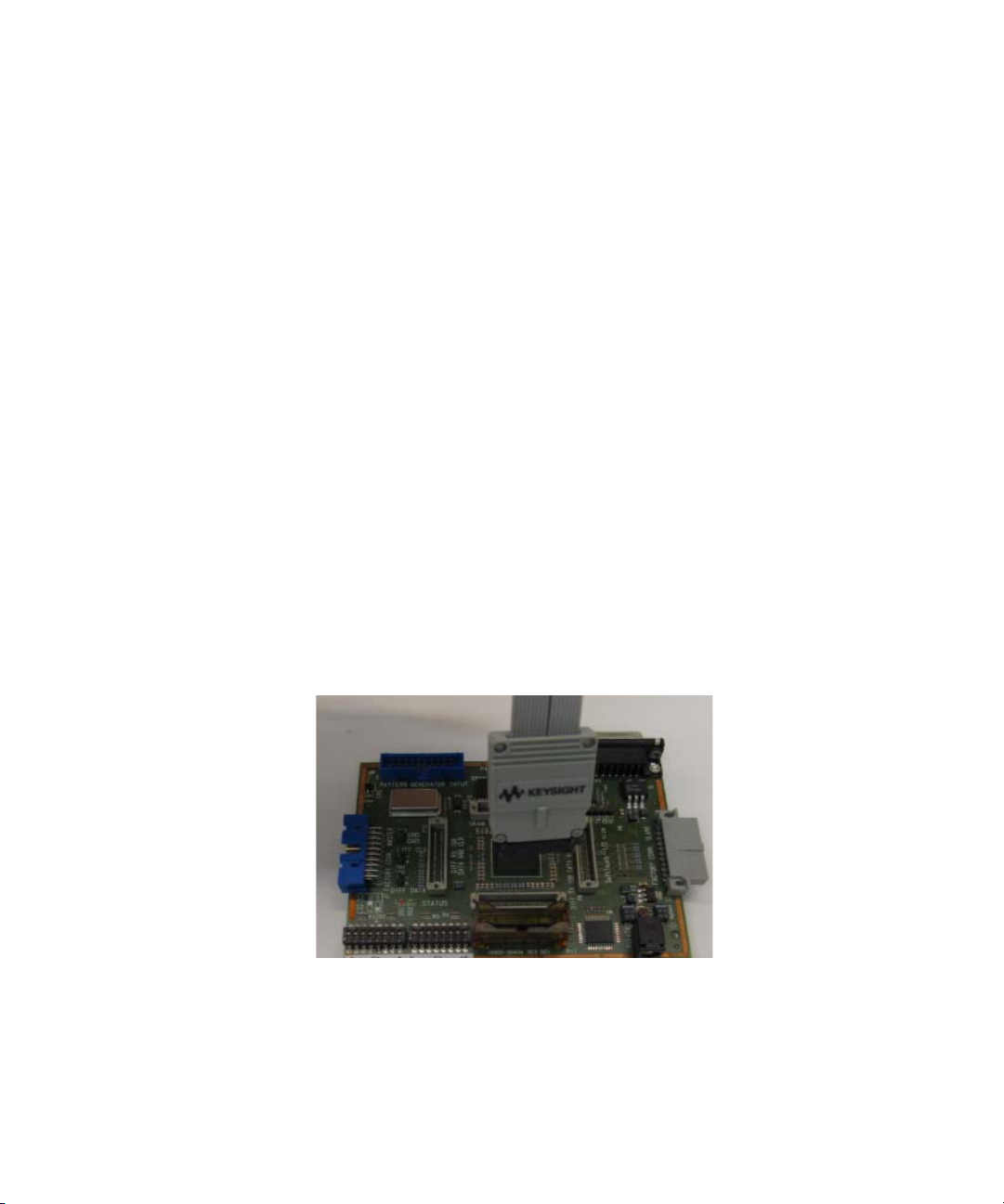
The U4205A 34-channel 38-pin Single-ended Mictor Probe:
The U4205A is a 34-channel single-ended Mictor probe which is
compatible with the 160-pin interface on logic analyzers including the
Keysight 16850-series portable logic analyzers and U4154A logic analysis
AXIe-based modules. For more information on Keysight logic analyzers,
refer to http://www.keysight.com/find/logicanalyzer. For more
information on your specific analyzer, refer to the Online help.
• Compatible with the 16850 Series and U4154A
• Compatible with boards designed for Keysight E5346A
• 34 Channels
• State speeds up to 600 Mb/s
• 300 mV peak- to- peak sensitivity
• 38- pin MICTOR connector
• Requires AMP MICTOR 38 connector and Keysight support
see page 32
38- pin probe
shroud
Figure 1 E5386A half channel adapter
8 Keysight U4205A Direct Connect 34-Channel Mictor Probe
Page 9
Introduction to U4205A Use
Descriptions of U4205A direct connect probe
Number of probes required
Probe Logic Analyzer Module
U4205A 38-pin single-ended probe 4 1 2 3 4
U4205A Overview 1
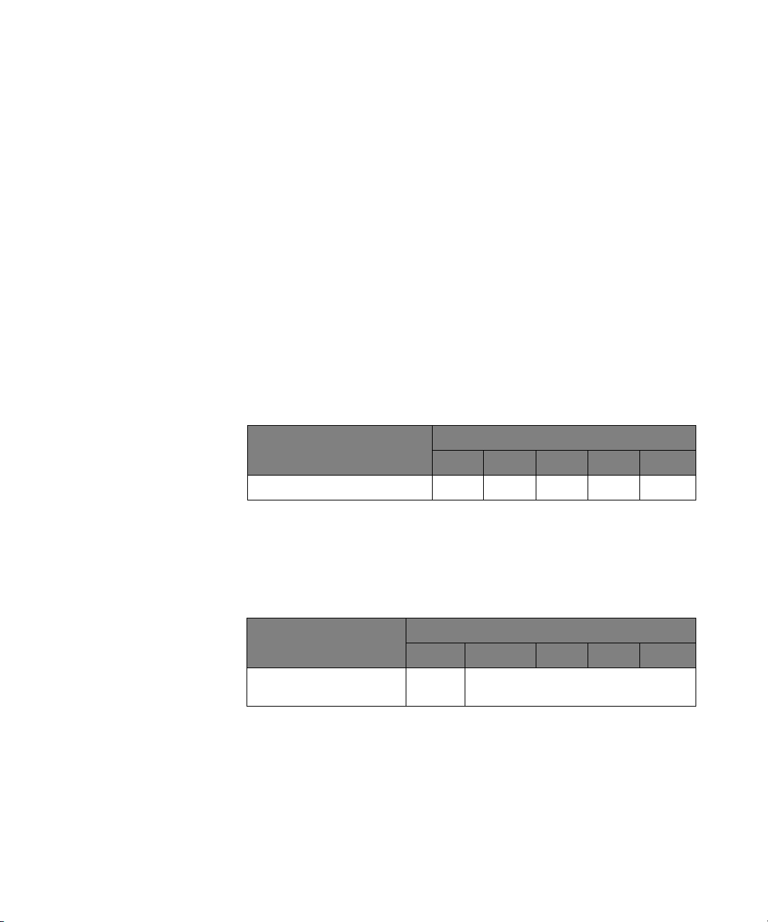
This chapter provides information to help you utilize the U4205A. Tables in
this chapter show you the number of probes required and the maximum
state speed supported depending
on which logic analyzer you have.
Another table shows the number of data and clock inputs for the various
operating modes of your logic analyzer.
• U4205A Direct Connect 34-Channel 38-pin single-ended probe
This table shows how many probes are required to provide connections to
all channels of your logic analyzer module.
Table 1 Number of probes required
U4154A 16851A 16852A 16853A 16854A
Maximum state speed supported
This table gives you the maximum state speed that is
supported by the
combination of a probe and your logic analyzer module.
Table 2 Maximum state speed supported
Probe Logic Analyzer Module
U4154A 16851A 16852A 16853A 16854A
U4205A 38-pin single-ended
probe
Keysight U4205A Direct Connect 34-Channel Mictor Probe 9
600 Mb/s 600 Mb/s
Page 10
1 U4205A Overview
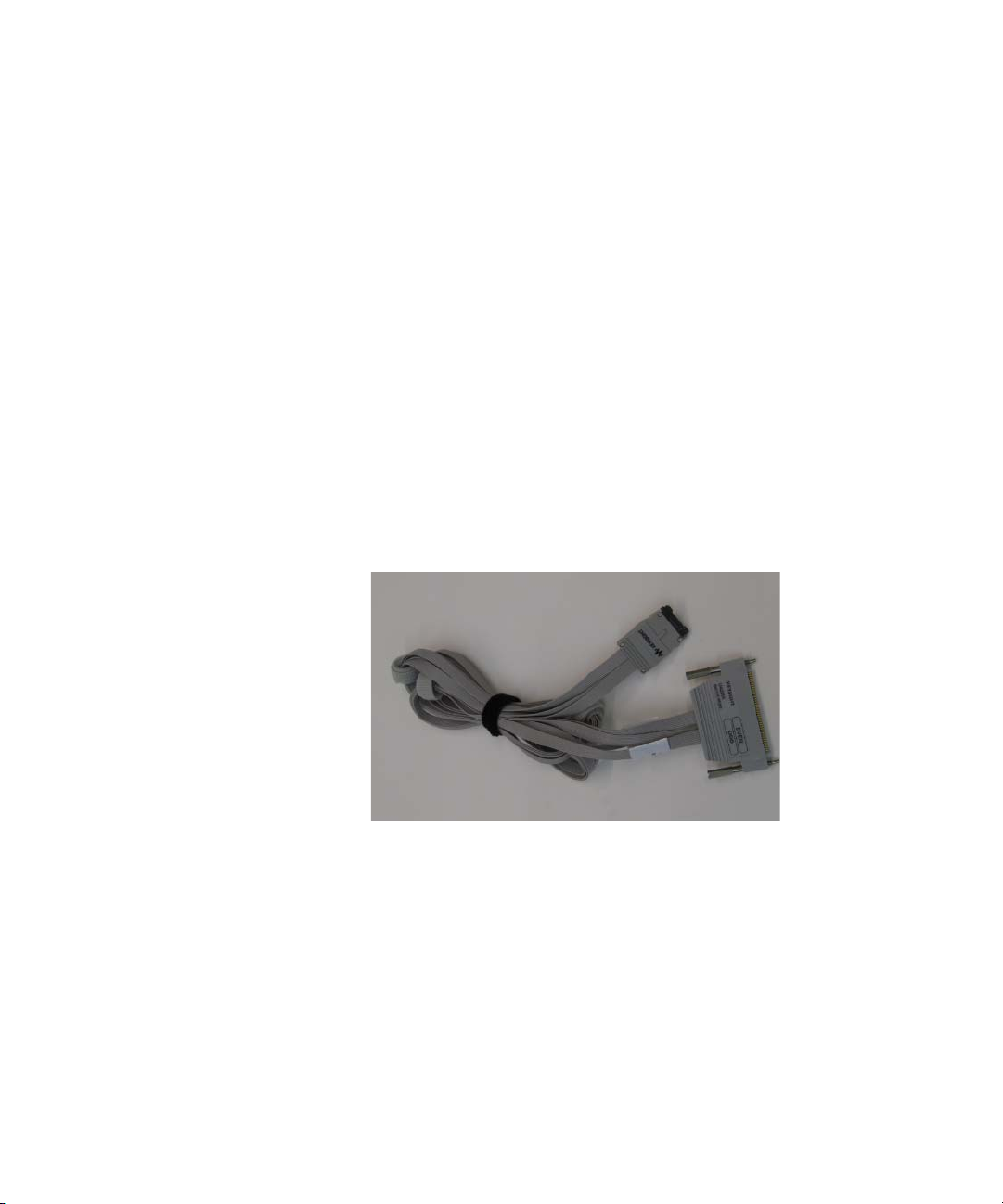
The U4205A 34-Channel 38-pin Single-Ended Mictor Probe
The U4205A is a direct connect, 34- channel, single- ended, 38- pin probe
designed to be compatible with the AMP MICTOR 38- pin connector. It is
pin- compatible with target systems that were designed for the Keysight
E5346A 38- pin probe, thus enabling you to use Keysight's latest logic
analyzers with target systems that were designed for older Keysight logic
analyzers. The U4205A is compatible with the Keysight 16851A,
16852A,16853A and 16854A portable logic analyzers, and the U4154A
logic analyzer module. It is capable of capturing state (synchronous) data
at clock speeds up to 600 MHz, at data rates up to 600 Mb/s, with signal
amplitudes as small as 300 mV peak- to- peak.
The Keysight E5346- 68701 or E5346- 68700 probing connector kit is
required for connecting the U4205A probe to your target system. The kit
contains five mating connectors and five support shrouds. The connectors
and shrouds may be ordered separately if desired. See the table on
page 32 for part numbers.
Figure 2 U4205A 38-pin single-ended probe
See Also: Chapter 2 for the mechanical information to design the connector
into your target system boards.
10 Keysight U4205A Direct Connect 34-Channel Mictor Probe
Page 11

Keysight U4205A Direct Connect 34-Channel Mictor
Probe
User Guide
2 Mechanical
Considerations
Characteristics / 12
Probe Dimensions / 13
MICTOR Connector Dimensions / 14
Support Shroud Dimensions / 15
Footprint Dimensions / 16
U4205A 38-pin single-ended probe pin out table / 17
This chapter describes mechanical considerations and dimensions of
U4205A 34-channel single-ended Mictor probe.
Page 12

2 Mechanical Considerations
Characteristics
Electrical considerations such as equivalent probe loads, input impedance,
and time domain transmission are shown in chapters 3 and 4 of this manual.
Other characteristics are
using.
dependent on the logic analyzer module you are
12 Keysight U4205A Direct Connect 34-Channel Mictor Probe
Page 13
Probe Dimensions
Mechanical Considerations 2
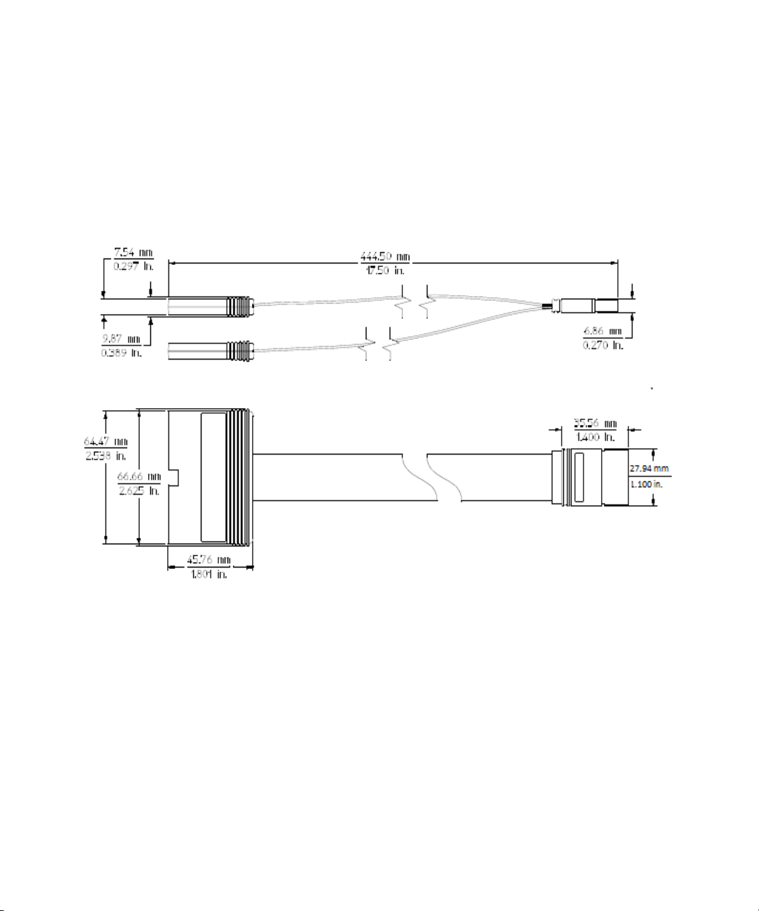
The following figure shows the dimensions of the 38- pin single- ended
probe.
Figure 3 U4205A 38-pin single-ended probe dimensions
Keysight U4205A Direct Connect 34-Channel Mictor Probe 13
Page 14
2 Mechanical Considerations
MICTOR Connector Dimensions
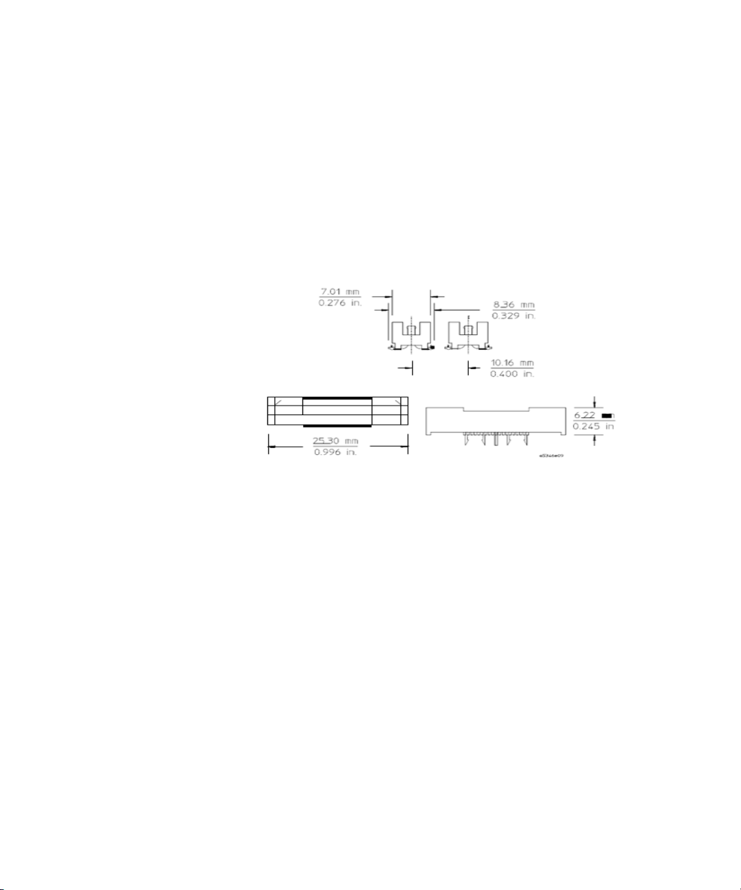
The U4205A probe is compatible with target systems designed for the
Keysight E5346A 38- pin probe. This probe requires a probe kit that
contains MICTOR connectors and
numbers.
shrouds. Refer to page 32 for the kit part
Figure 4 MICTOR 38-pin connector dimensions
14 Keysight U4205A Direct Connect 34-Channel Mictor Probe
Page 15
Support Shroud Dimensions
Bottom View
Mechanical Considerations 2
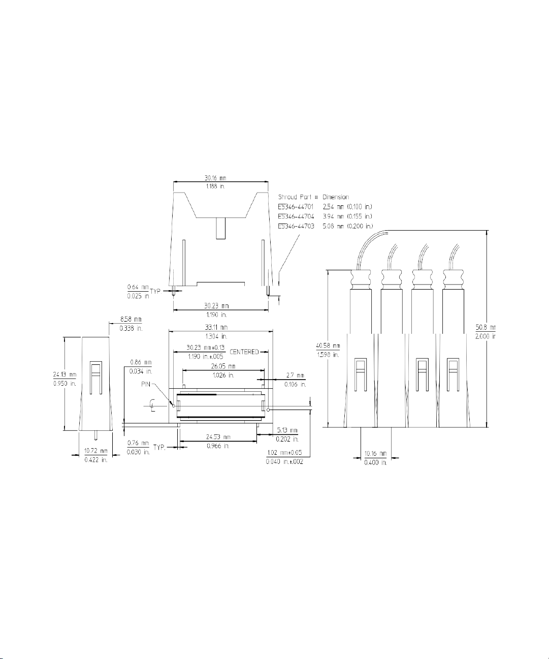
Support shrouds are not required but are recommended if pulling forces
may be applied to the cables that could cause the connector to be
dislodged. Refer to page 32 for the kit
part numbers.
Figure 5 Support shroud dimensions for the MICTOR 38-pin connector
Keysight U4205A Direct Connect 34-Channel Mictor Probe 15
Page 16
2 Mechanical Considerations
Footprint Dimensions
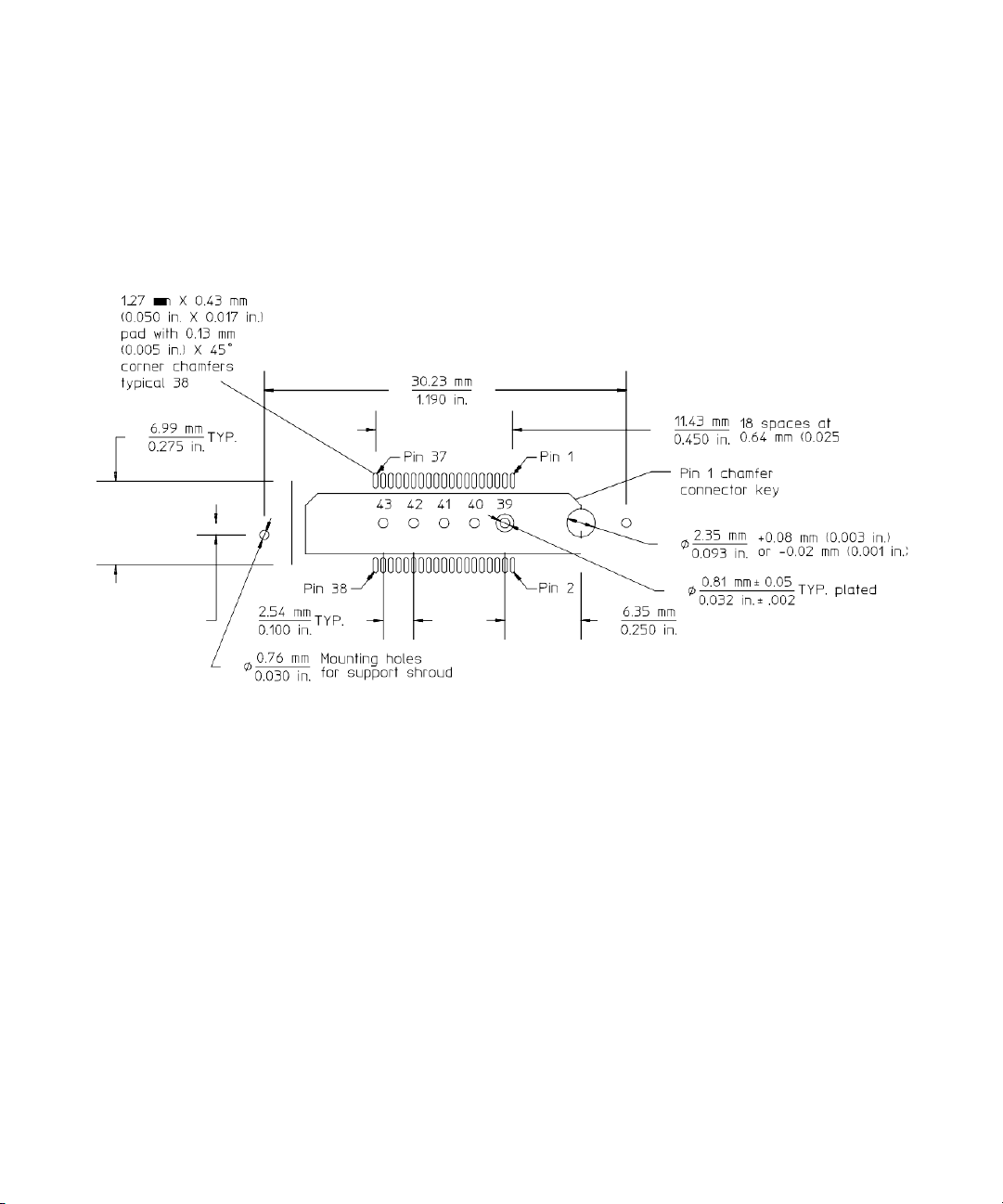
Use the following 38- pin MICTOR connector footprint and support shroud
mounting hole dimensions to design your target system board.
Figure 6 38-pin MICTOR connector footprint and support shroud mounting hole
16 Keysight U4205A Direct Connect 34-Channel Mictor Probe
dimensions
Page 17
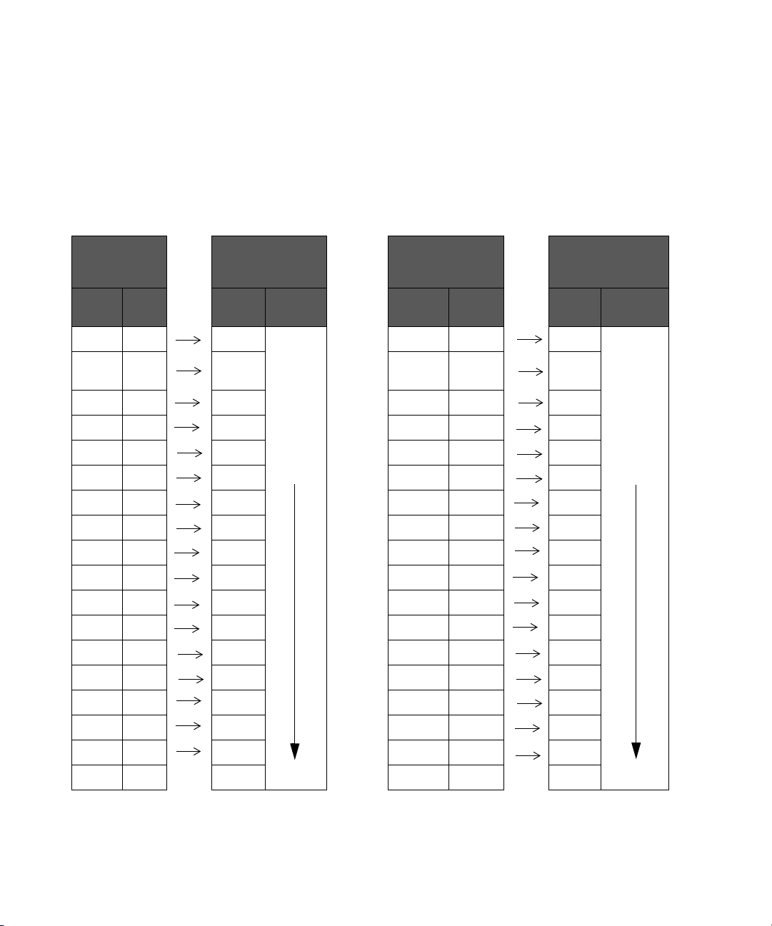
U4205A 38-pin single-ended probe pin out table
The following table lists the signal, Mictor pin number and the channel
values of the U4205A 38-pin single-ended probe.
Table 3 U4205A 38-pin single-ended probe pin out table
Mechanical Considerations 2
U4205A
Single-ended
Probe
Signal
Name
Clk 5 Clk Which
D 15 7
D 14 9 14 D 14 10 14
D 13 11 13 D 13 12 13
D 12 13 12 D 12 14 12
D 11 15 11 D 11 16 11
D 10 17 10 D 10 18 10
D 9 19 9 D 9 20 9
D 8 21 8 D 8 22 8
D 7 23 7 D 7 24 7
D 6 25 6 D 6 26 6
D 5 27 5 D 5 28 5
D 4 29 4 D 4 30 4
Mictor
Pin
12
Logic Analyzer U4205A Single-ended
Channel Pod Signal
ever pod is
connected
to “Even”
on the
U4205A
probe
Probe
Name
Clk 6 Clk Whichever
D 15 8
Mictor
Pin
15
Logic Analyzer
Channel Pod
pod is
connected
to “Odd”
on the
U4205A
probe
D 3 31 3 D 3 32 3
D 2 33 2 D 2 34 2
D 1 35 1 D 1 36 1
D 0 37 1 D 0 38 1
Ground 39-43 Ground 39-43
Keysight U4205A Direct Connect 34-Channel Mictor Probe 17
Page 18

2 Mechanical Considerations
NOTE
Do not connect the following pins. These pins are +5 volt supply and DC return
for analysis probes.
+5 V dc 1
Ground 3
Do not connect the following pins. They are used by the Keysight logic analyzer
with an emulator or analysis probe to program or read target information.
SCL 2
SDA 4
18 Keysight U4205A Direct Connect 34-Channel Mictor Probe
Page 19

Keysight U4205A Direct Connect 34-channel Mictor
Probe
User Guide
3 Operating U4205A
Probe
Equivalent Probe Load / 20
This chapter describes load specifications for operating U4205A
34-channel single-ended Mictor probe.
Page 20
3 Operating U4205A Probe
Equivalent Probe Load
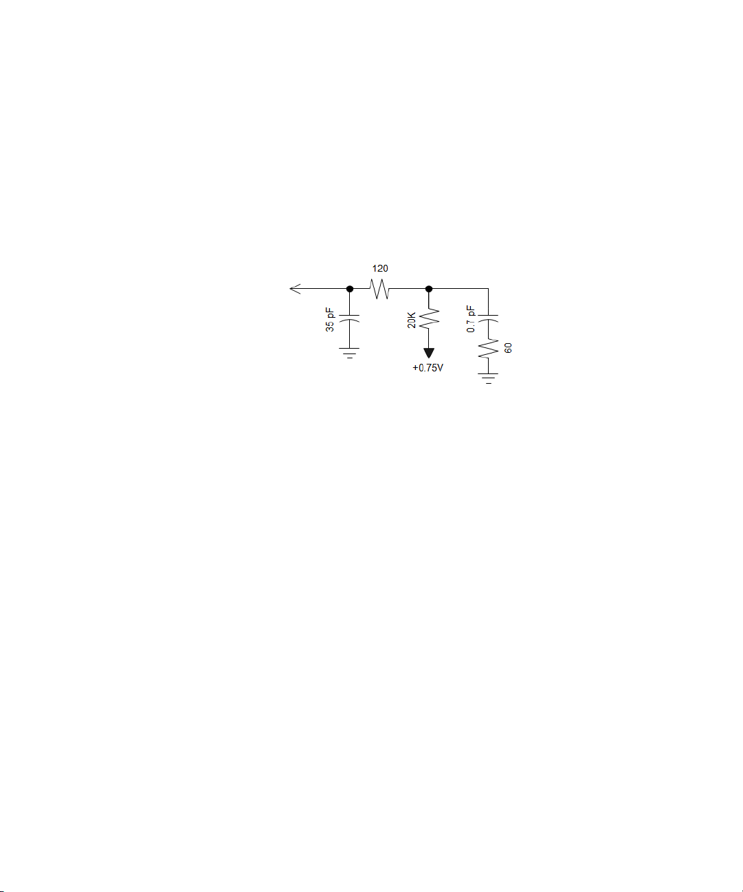
The equivalent probe load for the U4205A probe is shown in the figure
below. It includes the 38- pin MICTOR connector and the target connector.
The model is accurate up to 1 GHz.
Figure 7 Equivalent load for U4205A
20 Keysight U4205A Direct Connect 34-Channel Mictor Probe
Page 21
Measured versus modeled input impedance
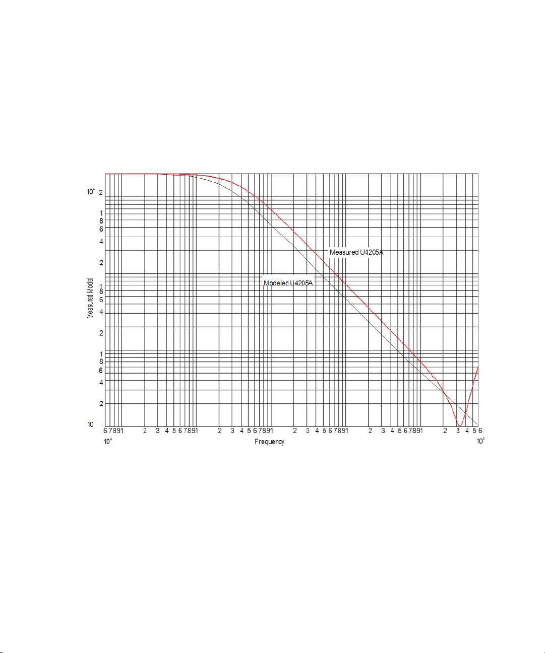
The U4205A probes have an input impedance which varies with frequency,
and depends on which accessories are being used. The following graph
shows the input impedance of the probe.
Operating U4205A Probe 3
Figure 8 Measured versus modeled input impedance
Keysight U4205A Direct Connect 34-Channel Mictor Probe 21
Page 22

3 Operating U4205A Probe
22 Keysight U4205A Direct Connect 34-Channel Mictor Probe
Page 23

Keysight U4205A Direct Connect 34-Channel Mictor
Probe
User Guide
4 Circuit Board Design
Transmission Line Considerations / 24
16850 Series and U4154A Data and Clock Inputs per Operating Mode / 25
Thresholds / 26
Signal Access / 27
This chapter describes design considerations for circuit board layout for
U4205A 34-channel single-ended Mictor probe.
Page 24

4 Circuit Board Design
Transmission Line Considerations
Stubs connecting signal transmission lines to the connector should be as
short as feasible. Longer stubs will cause more loading and reflections on a
transmission line. If the
signal rise time, it can be modeled as a lumped capacitance. Longer stubs
must be treated as transmission lines.
Example
Assume you are using FR-4 PC board material with a dielectric constant of
~4.3 for inner-layer traces (microstrip). For example, A 0.28 cm long stub
in an inner layer has a propagation delay of ~20 ps. Therefore, for a signal
with a rise time of 100 ps or greater, a 0.28 cm stub will behave like a
capacitor.
The trace capacitance per unit length will depend on the trace width and
the spacing to ground or power planes. If the trace is laid out to have a
characteristic impedance of 50 ohms, it turns out that the capacitance per
unit length is ~ 1.2 pF/cm. Therefore, the 0.28 cm stub in the previous
example would have an effective capacitance equal to ~0.34 pF.
This trace capacitance is in addition to the probe load
electrical length of a stub is less than 1/5 of the
model.
24 Keysight U4205A Direct Connect 34-Channel Mictor Probe
Page 25
Circuit Board Design 4
NOTE
16850 Series and U4154A Data and Clock Inputs per Operating Mode
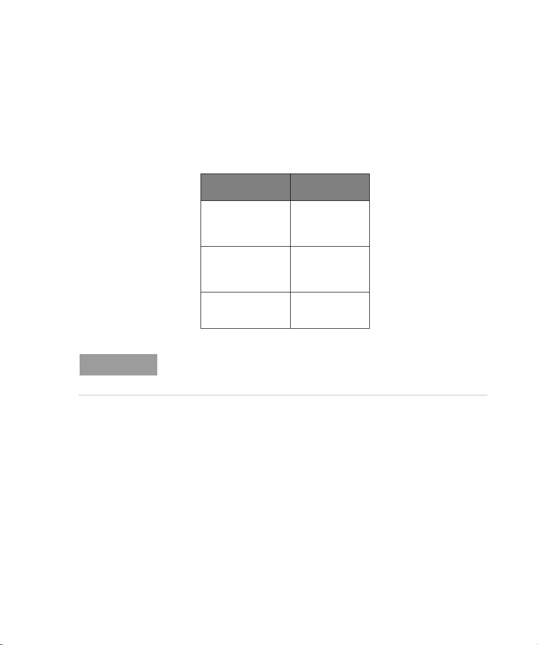
The following table shows the number of data and clock inputs for each
connector on your target system for the various operating modes of your
U4154A and 16850 Series logic analyzer.
Table 4 Data clock inputs per operating mode
U4154A and 16850 Series
Operating Mode
Synchronous (state)
analysis maximum
800 Mb/s
Eye scan mode 800 Mb/s 32 data
Timing mode 32 data
U4205A
32 data
plus 2
clock inputs
(see Note below)
plus 2
clock inputs
(see Note below)
plus 2
clock inputs
In synchronous (state) analysis mode, and in the eye scan mode, there is one
clock input which must be routed to the clock input on pod 1. The clock inputs
on other pods can be assigned to labels and acquired as data inputs.
Keysight U4205A Direct Connect 34-Channel Mictor Probe 25
Page 26

4 Circuit Board Design
Thresholds
U4205A Direct-Connect 34-Channel 38-pin Single-Ended Mictor Probe
All inputs in the U4205A 38-pin probe are single- ended. The
does not have a threshold reference input. When you use the U4205A, you
adjust the logic threshold in the user interface.
The clock input on the U4205A is sing le- ended. The clock
adjusted independent of the data.
U4205A
threshold may be
probe
26 Keysight U4205A Direct Connect 34-Channel Mictor Probe
Page 27

Signal Access
Circuit Board Design 4
Labels split across probes
Re-ordered bits
If a label is split across more than one pod, this may lead to
triggering. Refer to "Triggering with the Keysight 16760A" (Keysight
publication number 5988- 2994EN) for more details. Triggering restrictions
across more than one pod may or may not apply depending upon the
actual configuration.
If bits need to be reordered within a label, this leads to
restrictions in triggering. Specifically, equalities can be used to evaluate the
value of a label with reordered
may be able to avoid the need to reorder bits in a label by routing signals to
appropriate pins on the probe connector. Refer to “Triggering with the
Keysight 16760A" (Keysight publication
details.
bits, but inequalities cannot be used. You
number 5988- 2994EN) for more
restrictions in
additional
Keysight U4205A Direct Connect 34-Channel Mictor Probe 27
Page 28

4 Circuit Board Design
28 Keysight U4205A Direct Connect 34-Channel Mictor Probe
Page 29

Keysight U4205A Direct Connect 34-Channel Mictor
Probe
User Guide
5 Recommended
Reading
For More Information / 30
This chapter lists the recommended reading for more information about
systems and high- speed digital design.
Page 30

5 Recommended Reading
For More Information
MECL System Design Handbook
High-speed Digital Design
Designing High-speed Target Systems for Logic Analyzer Probing
For more information on Keysight logic analyzers, refer to
http://www.keysight.com/find/logicanalyzer.For more information on
your specific analyzer, refer to the online help in the product.
Blood, William R. Jr., "MECL System Design Handbook," 4th edition, 1988,
published by Motorola. This handbook can be obtained from ON
Semiconductor on the web. Go to
<http://onsemi.com>. Click on "On- line ordering" under
"Documentation." Click on the link "General search." Type in "HB205" in
the "Document number" field. Click "Submit." To view the document
online, click on "PDF" in the right- hand column titled "PDF MFAX." Or
order a hardcopy of the handbook on- line.
Johnson, Howard W., and Martin Graham, "High- speed Digital Design,"
Prentice- Hall, 1993, ISBN 0- 13- 395724- 1
“Designing High- speed Target Systems for Logic Analyzer
Keysight Technologies application note publication
30 Keysight U4205A Direct Connect 34-Channel Mictor Probe
Probing”
number 5988- 2989EN.
Page 31

Keysight U4205A Direct Connect 34-Channel Mictor
Probe
User Guide
6 Connectors and
Shrouds
Ordering Probing Connectors and Shrouds / 32
This chapter lists the Keysight part numbers of the Probes and their
corresponding Targets.
Page 32
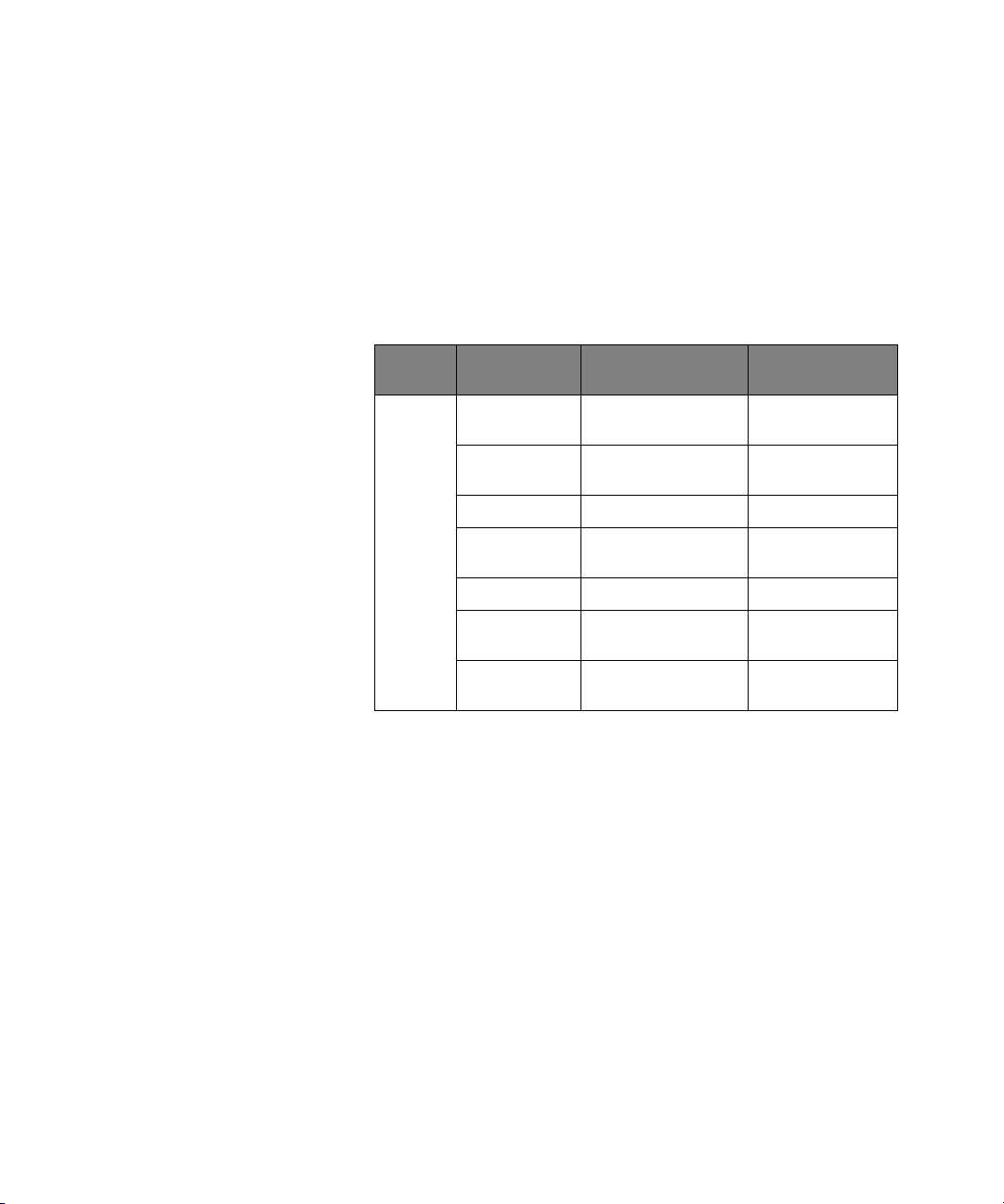
6 Connectors and Shrouds
Ordering Probing Connectors and Shrouds
Connectors and shrouds may be ordered in kits or ordered separately.
Select a support shroud appropriate for the thickness of your PC board. The
following table lists the
connectors and shrouds.
Table 5 Keysight part numbers
Keysight part numbers for each of these
For Probes
Model #
U4205A E5346-68701 5 MICTOR Connectors
Keysight Part
Number
E5346-68700 5 MICTOR Connectors
1252-7431 1 MICTOR Connector n/a
AMP part
#2-767004-2
E5346-44701 1 Support Shroud up to 1.57 mm (0.062”)
E5346-44704 1 Support Shroud 1.575 to 3.175 mm
E5346-44703 1 Support Shroud 3.175 to 4.318 mm
Consists of For Target PC Board
& 5 Support Shrouds
& 5 Support Shrouds
1 MICTOR Connector n/a
Thickness
up to 1.57 mm (0.062
in.)
1.575 to 3.175 mm
(0.062 to 0.125 in.)
(0.062 to 0.125 in.)
(0.125 to 0.70 in.)
32 Keysight U4205A Direct Connect 34-Channel Mictor Probe
Page 33

Safety Information
CAUTION
The following general safety precautions must be observed during all phases of operation
of this instrument. Failure to comply with these precautions or with specific warnings or
operating instructions in the product manuals violates safety standards of design, manufacture, and intended use of the instrument. Keysight Technologies assumes no liability for
the customer's failure to comply with these requirements. Product manuals are provided
with your instrument on CD-ROM and/or in printed form. Printed manuals are an option
for many products. Manuals may also be available on the Web. Go to www.keysight.com
and type in your product number in the Search field at the top of the page.
General Do not use this product in any manner not specified by the manufacturer. The protective
features of this product may be impaired if it is used in a manner not specified in the operation instructions.
Before Applying Power Verify that all safety precautions are taken. Make all connections to the unit before
applying power. Note the instrument's external markings described in “Safety Symbols”.
Ground the Instrument If your product is provided with a grounding type power plug, the instrument chassis and
cover must be connected to an electrical ground to minimize shock hazard. The ground
pin must be firmly connected to an electrical ground (safety ground) terminal at the
power outlet. Any interruption of the protective (grounding) conductor or disconnection
of the protective earth terminal will cause a potential shock hazard that could result in
personal injury.
Fuses See the user's guide or operator's manual for information about line-fuse replacement.
Some instruments contain an internal fuse, which is not user accessible.
Do Not Operate in an
Do not operate the instrument in the presence of flammable gases or fumes.
Explosive Atmosphere
Do Not Remove the
Instrument Cover
Only qualified, service-trained personnel who are aware of the hazards involved should
remove instrument covers. Always disconnect the power cable and any external circuits
before removing the instrument cover.
Cleaning Clean the outside of the instrument with a soft, lint-free, slightly dampened cloth. Do not
use detergent or chemical solvents.
Do Not Modify the
Instrument
Do not install substitute parts or perform any unauthorized modification to the product.
Return the product to Keysight Sales and Service Office for service and repair to ensure
that safety features are maintained.
In Case of Damage Instruments that appear damaged or defective should be made inoperative and secured
against unintended operation until they can be repaired by qualified service personnel.
A CAUTION notice denotes a hazard. It calls attention to an operating procedure, practice,
or the like that, if not correctly performed or adhered to, could result in damage to the
product or loss of important data. Do not proceed beyond a CAUTION notice until the
indicated conditions are fully understood and met.
Keysight U4205A Direct Connect 34-Channel Mictor Probe 33
Page 34
WARNING
A WARNING notice denotes a hazard. It calls attention to an operating procedure,
practice, or the like that, if not correctly performed or adhered to, could result in
personal injury or death. Do not proceed beyond a WARNING notice until the indicated
conditions are fully understood and met.
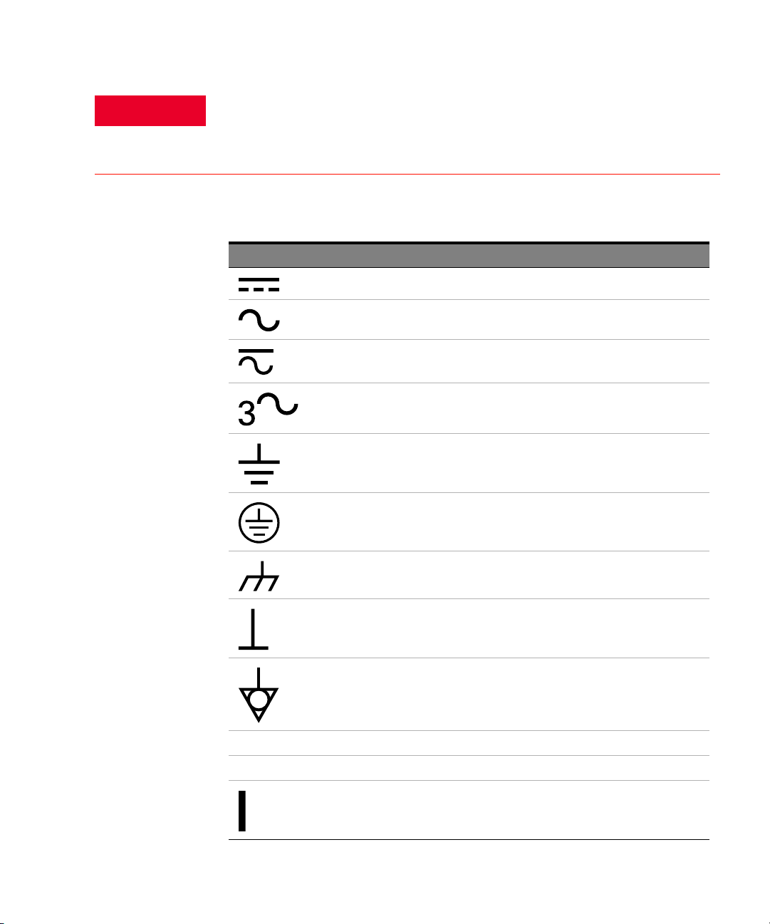
Safety Symbols
Symbol Description
Direct current
Alternating current
Both direct and alternating current
Three phase alternating current
Earth ground terminal
Protective earth ground terminal
Frame or chassis ground terminal
Terminal is at earth potential
Equipotentiality
N Neutral conductor on permanently installed equipment
L Line conductor on permanently installed equipment
On (mains supply)
34 Keysight U4205A Direct Connect 34-Channel Mictor Probe
Page 35
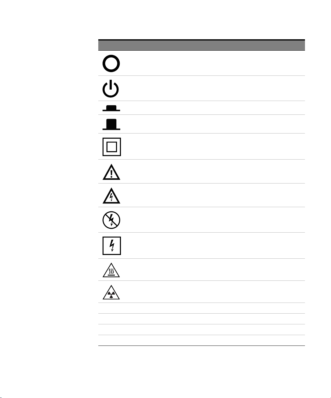
Symbol Description
Off (mains supply)
Standby (mains supply). The instrument is not completely disconnected from the mains supply
when the power switch is in the stand by position
In position of a bi-stable push switch
Out position of a bi-stable push switch
Equipment protected throughout by DOUBLE INSULATION or REINFORCED INSULATION
Caution, refer to accompanying documentation
Caution, risk of electric shock
Do not apply around or remove from HAZARDOUS LIVE conductors
Application around and removal from HAZARDOUS LIVE cond uctors is permitted
Caution, hot surface
Ionizing radiation
CAT I IEC Measurement Category I
CAT II Measurement Category II
CAT III Measurement Category III
CAT IV Measurement Category IV
Keysight U4205A Direct Connect 34-Channel Mictor Probe 35
Page 36

Informations relatives à la sécurité
Les consignes de sécurité générales présentées dans cette section doivent être appliquées
au cours des différentes phases d'utilisation de cet appareil. Le non-respect de ces précautions ou des avertissements et consignes d'utilisation spécifiques mentionnés dans les
manuels des produits constitue une violation des normes de sécurité relatives à la conception, à la fabrication et à l'usage normal de l'instrument. Keysight Technologies ne saurait
être tenu responsable du non-respect de ces consignes. Les manuels des produits sont
fournis avec votre instrument sur CD-ROM et/ou en version papier. Les versions papier des
manuels sont en option pour de nombreux produits. Certains manuels sont également disponibles en ligne. Pour y accéder, allez sur le site www.keysight.com et saisissez la
référence de votre produit dans le champ Rechercher qui se trouve en haut de la page.
Généralités Utilisez ce produit uniquement dans le cadre prévu par le fabricant. Si vous ne respectez
pas les instructions d'utilisation, les fonctions de sécurité du produit risquent d'être inhibées.
Avant la mise sous tension Vérifiez que vous avez bien respecté toutes les consignes de sécurité. Faites tous les
branchements au niveau de l'appareil avant de mettre ce dernier sous tension. Tenez
compte des marquages externes à l'instrument décrits à la section «Symboles de sécurité».
Mise à la terre de
l'instrument
Si une prise de mise à la terre est fournie avec le produit, le châssis et le capot de l'instrument doivent être reliés à la terre afin de limiter les risques d'électrocution. Le contact à
la terre doit être solidement connecté à une borne de terre (de sécurité) au niveau de la
prise de courant . Toute interruption du conducteur de protection (mise à la terre) ou tout
débranchement de la borne de terre de protection donne lieu à un risque d'électrocution
pouvant entraîner des blessures graves.
Fusibles Pour obtenir des instructions sur le changement des fusibles de ligne, consultez le guide
de l'utilisateur ou le manuel d'instructions. Certains instruments comportent un fusible interne inaccessible à l'utilisateur.
Ne pas utiliser en
N'utilisez pas l'instrument en présence de gaz ou de vapeurs inflammables.
atmosphère explosive
Ne pas démonter le capot
de l'instrument
Seules des personnes qualifiées, formées à la maintenance et conscientes des risques
d'électrocution encourus sont autorisées à démonter les capots de l'instrument. Débranchez toujours le cordon d'alimentation secteur et tous les circuits externes avant de
démonter le capot de l'instrument.
Nettoyage Nettoyez la partie externe de l'instrument à l'aide d'un chiffon doux et non pelucheux,
légèrement humidifié. N'utilisez pas de détergents ou de solvants chimiques.
Ne pas modifier
l'instrument
N'installez pas de composants de remplacement et n'apportez aucune modification non
autorisée à l'appareil. Pour toute opération de maintenance ou de réparation, renvoyez
l'appareil à un bureau de vente et de service après-vente keysight, afin d'être certain que
les fonctions de sécurité seront maintenues.
En cas de dommages Les instruments endommagés ou défectueux doivent être désactivés et protégés contre
toute utilisation involontaire jusqu'à ce qu'ils aient été réparés par une personne qualifiée.
36 Keysight U4205A Direct Connect 34-Channel Mictor Probe
Page 37
La mention ATTENTION indique un risque. Si la manoeuvre ou le procédé correspondant
n'est pas exécuté correctement, il peut y avoir un risque de dommages à l'appareil ou de
perte de données importantes. En présence de la mention ATTENTION, il convient de
s'interrompre tant que les conditions indiquées n'ont pas été parfaitement comprises et
respectées.
La mention AVERTISSEMENT signale un danger pour la sécurité de l'opérateur. Si la
manœuvre ou le procédé correspondant n'est pas exécuté correctement, il peut y avoir
un risque pour la santé des personnes. En présence d'une mention AVERTISSEMENT, il
convient de s'interrompre tant que les conditions indiquées n'ont pas été parfaitement
comprises et respectées.
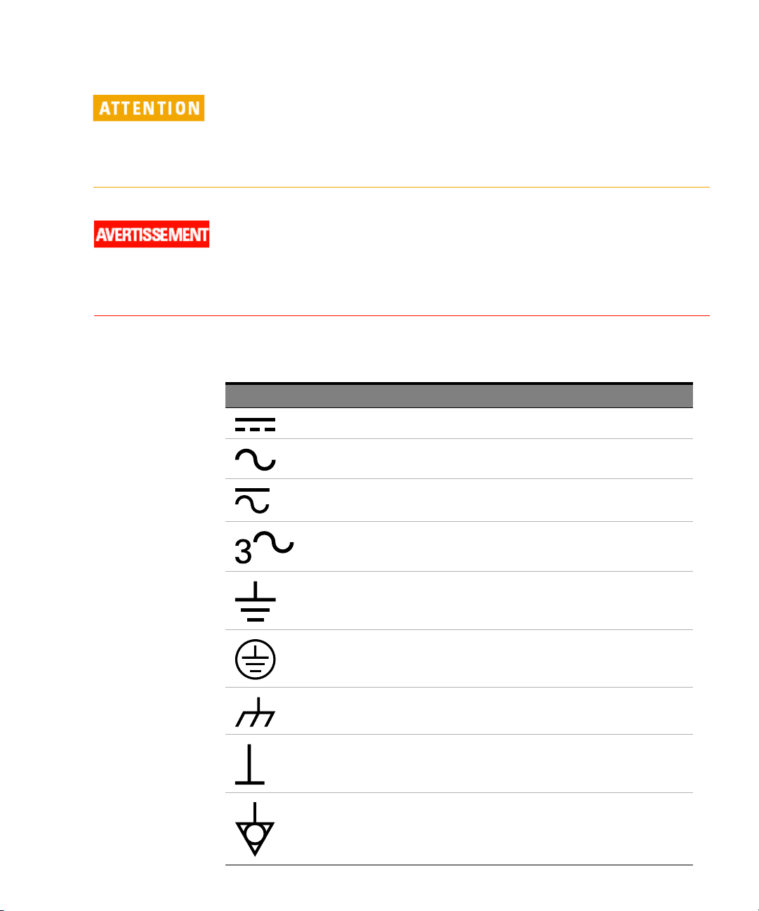
Symboles de sécurité:
Symboles Description
Courant continu.
Courant alternatif.
Courant continu et alternatif.
Courant alternative triphasé.
Borne de terre (masse).
Borne de terre de protection.
Borne de terre reliée au cadre ou au châssis.
Borne au potentiel de la terre.
Equipotentialité
Keysight U4205A Direct Connect 34-Channel Mictor Probe 37
Page 38
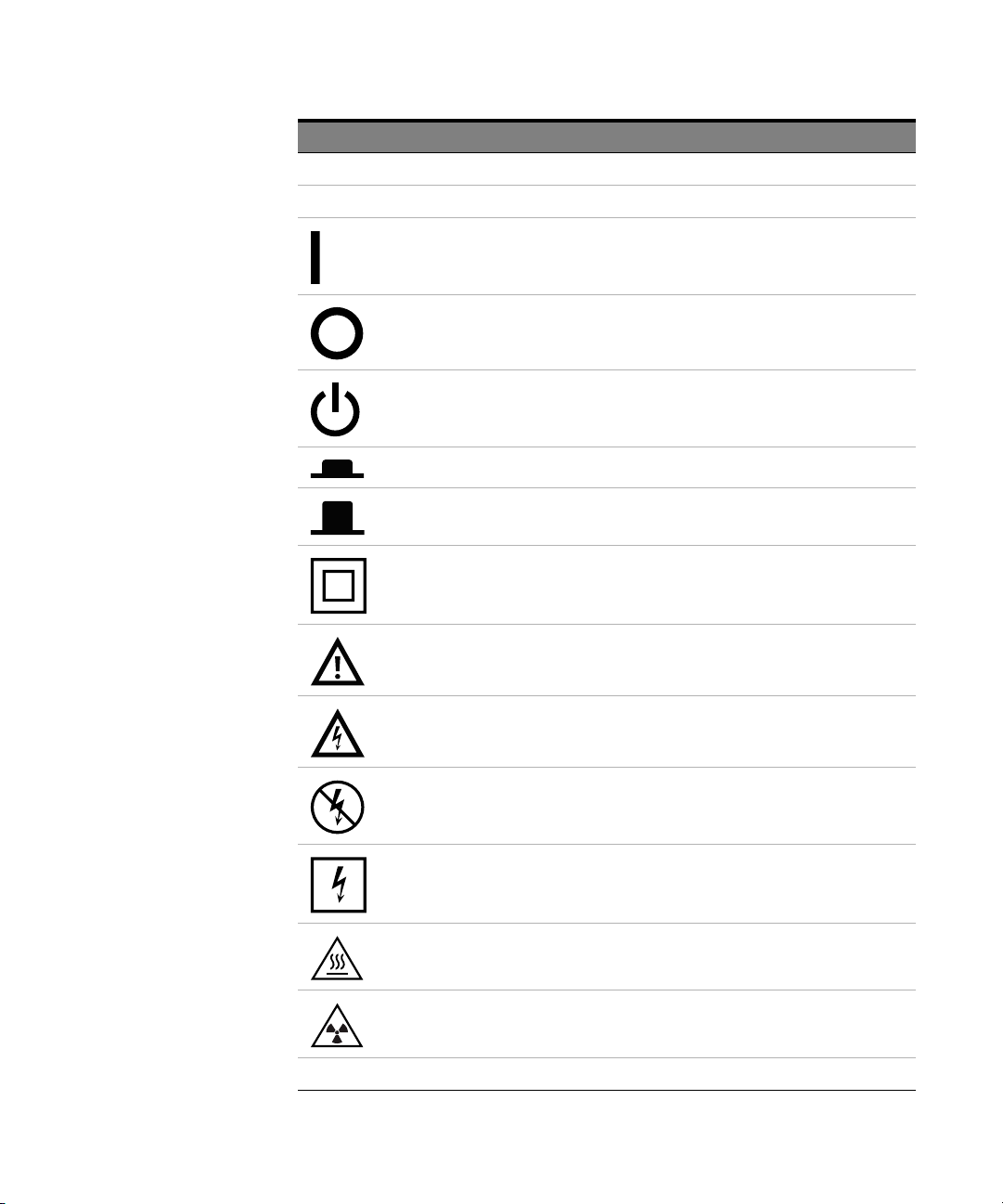
Symboles Description
N Conducteur neutre sur un équipement installé à demeure
L Conducteur de phase sur un équipement installé à demeure.
Alimentation en marche.
Alimentation à l'arrêt.
Alimentation en mode veille. Lorsque l'interrupteur est en mode veille, l'unité n'est pas
complètement déconnectée de l'alimentation secteur.
Position Marche d'un interrupteur par bouton poussoir bi-stable.
Position Arrêt d'un interrupteur par bouton poussoir bi-stable.
Appareil entièrement protégé par DOUBLE ISOLATION ou ISOLATION RENFORCÉE
Attention. Consultez la documentation fournie.
Attention, danger d'électrocution.
Ne pas appliquer ou enlever sur des conducteurs SOUS TENSION DANGEREUSE
Application ou retrait autorisés sur les conducteurs SOUS TENSION DANGEREUSE
Attention, surface chaude
Rayonnement ionisant
CAT I Appareil de mesure de catégorie I selon la norme CEI applicable
38 Keysight U4205A Direct Connect 34-Channel Mictor Probe
Page 39

Symboles Description
CAT II Appareil de mesure de catégorie II selon la norme CEI applicable
CAT III Appareil de mesure de catégorie III selon la norme CEI appl icable
CAT IV Appareil de mesure de catégorie IV selon la norme CEI applicable
Keysight U4205A Direct Connect 34-Channel Mictor Probe 39
Page 40

40 Keysight U4205A Direct Connect 34-Channel Mictor Probe
 Loading...