

Page 1

Keysight U3606A
Multimeter | DC Power
Supply
Programmer’s
Reference
Page 2

Page 3

Page 4

Notices
CAUTION
WARNING
© Keysight Technologies 2009 - 2014
No p art o f this manu al may be re produce d in
any form or by any means (including electronic storage and retrieval or translation
into a foreign language) without prior agreement and written consent from Keysight
Technologies as governed by United States
and international copyright laws.
Manual Part Number
U3606-90023
Edition
Edition 5, August 2014
Keysight Technologies
1400 Fountaingrove Parkway
Santa Rosa, CA 95403
Warranty
The material contained in this document is provided “as is,” and is subject to being changed, without notice,
in future editions. Further, to the maximum extent permitted by applicable
law, Keysight disclaims all warranties, either express or implied, with
regard to this manual and any information contained herein, including
but not limited to the implied warranties of merchantability and fitness for
a particular purpose. Keysight shall
not be liable for errors or for incidental or consequential damages in connection with the furnishing, use, or
performance of this document or of
any information contained herein.
Should Keysight and the user have a
separate written agreement with
warranty terms covering the material
in this document that conflict with
these terms, the warranty terms in the
separate agreement shall control.
Technology Licenses
The hardware and or software described in
this document are furnished under a license
and may be used or copied only in accordance with the terms of such license.
Restricted Rights Legend
U.S. Government Restricted Rights. Software and technical data rights granted to
the federal government include only those
rights customarily provided to end user customers. Keysight provides this customary
commercial license in Software and technical data pursuant to FAR 12.211 (Technical
Data) and 12.212 (Computer Software) and,
for the Department of Defense, DFARS
252.227-7015 (Technical Data - Commercial
Items) and DFARS 227.7202-3 (Rights in
Commercial Computer Software or Computer Software Documentation).
Safety Notices
A CAUTION notice denotes a hazard. It calls attention to an operating procedure, practice, or the like
that, if not correctly performed or
adhered to, could result in damage
to the product or loss of important
data. Do not proceed beyond a
CAUTION notice until the indicated
conditions are fully understood and
met.
A WARNING notice denotes a
hazard. It calls attention to an
operating procedure, practice, or
the like that, if not correctly performed or adhered to, could result
in personal injury or death. Do not
proceed beyond a WARNING
notice until the indicated conditions are fully understood and
met.
II U3606A Programmer’s Reference
Page 5

Table of Contents
1 Introduction to SCPI
Introduction to the SCPI Language 2
SCPI Conventions and Data Formats 3
Command separators 4
Syntax conventions 8
Data types and formats 9
Input message terminators 10
Using device clear 11
SCPI Status System 12
Standard Event register 14
Status Byte register 15
Operation Status register 16
Questionable Status register 17
2 CALCulate Subsystem
CALCulate:FUNCtion 20
CALCulate[:STATe] 23
CALCulate:AVERage:AVERage? 25
CALCulate:AVERage:COUNt? 26
CALCulate:AVERage:MAXimum? 27
CALCulate:AVERage:MINimum? 28
CALCulate:AVERage:PRESent? 29
CALCulate:DB:REFerence 30
CALCulate:DBM:REFerence 32
CALCulate:HOLD:VARiation 34
CALCulate:HOLD:THReshold 36
U3606A Programmer’s Reference III
Page 6

CALCulate:LIMit:LOWer 38
CALCulate:LIMit:UPPer 40
CALCulate:NULL:OFFSet 42
3 CALibration Subsystem
CALibration[:ALL]? 46
CALibration:COUNt? 47
CALibration:SECure:CODE 48
CALibration:SECure:STATe 49
CALibration:STRing 51
CALibration:VALue 53
CALibration:LEVel 55
Remote Calibration Procedures 56
Zero offset adjustments 57
Gain adjustments 59
Output adjustments 75
4 CONFigure Subsystem
CONFigure? 80
CONFigure[:VOLTage][:DC] 81
CONFigure[:VOLTage]:AC 84
CONFigure[:VOLTage]:ACDC|DCAC 87
CONFigure:CURRent[:DC] 90
CONFigure:CURRent:AC 93
CONFigure:CURRent:ACDC|DCAC 96
CONFigure:RESistance 99
CONFigure:CONTinuity 102
IV U3606A Programmer’s Reference
Page 7

CONFigure:LRESistance 104
CONFigure:CAPacitance 107
CONFigure:DIODe 110
CONFigure:FREQuency 112
CONFigure:PWIDth 114
CONFigure:DCYCle 116
5 INITiate Subsystem
INITiate[:IMMediate] 120
INITiate:CONTinuous 122
6 MEASure Subsystem
MEASure[:VOLTage][:DC]? 126
MEASure[:VOLTage]:AC? 128
MEASure[:VOLTage]:ACDC|DCAC? 131
MEASure:CURRent[:DC]? 134
MEASure:CURRent:AC? 136
MEASure:CURRent:ACDC|DCAC? 138
MEASure:RESistance? 140
MEASure:CONTinuity? 143
MEASure:LRESistance? 145
MEASure:CAPacitance? 147
MEASure:DIODe? 150
MEASure:FREQuency? 151
MEASure:PWIDth? 153
MEASure:DCYCle? 155
U3606A Programmer’s Reference V
Page 8

7 MEMory Subsystem
MEMory:STATe:RECall:AUTO 158
8 OUTPut Subsystem
OUTPut[:STATe] 162
9 SENSe Subsystem
[SENSe:]FUNCtion[:ON] 165
[SENSe:]VOLTage[:DC]:RANGe[:UPPer] 167
[SENSe:]VOLTage[:DC]:RANGe:AUTO 169
[SENSe:]VOLTage[:DC]:RESolution 171
[SENSe:]VOLTage:AC:RANGe[:UPPer] 173
[SENSe:]VOLTage:AC:RANGe:AUTO 175
[SENSe:]VOLTage:AC:RESolution 177
[SENSe:]VOLTage:ACDC|DCAC:RANGe[:UPPer] 179
[SENSe:]VOLTage:ACDC|DCAC:RANGe:AUTO 181
[SENSe:]VOLTage:ACDC|DCAC:RESolution 183
[SENSe:]CURRent[:DC]:RANGe[:UPPer] 185
[SENSe:]CURRent[:DC]:RANGe:AUTO 187
[SENSe:]CURRent[:DC]:RESolution 189
[SENSe:]CURRent:AC:RANGe[:UPPer] 191
[SENSe:]CURRent:AC:RANGe:AUTO 193
[SENSe:]CURRent:AC:RESolution 195
[SENSe:]CURRent:ACDC|DCAC:RANGe[:UPPer] 197
[SENSe:]CURRent:ACDC|DCAC:RANGe:AUTO 199
[SENSe:]CURRent:ACDC|DCAC:RESolution 201
VI U3606A Programmer’s Reference
Page 9

[SENSe:]RESistance:RANGe[:UPPer] 203
[SENSe:]RESistance:RANGe:AUTO 205
[SENSe:]RESistance:RESolution 207
[SENSe:]CONTinuity:RANGe[:UPPer] 209
[SENSe:]CONTinuity:RANGe:AUTO 211
[SENSe:]LRESistance:RANGe[:UPPer] 213
[SENSe:]LRESistance:RANGe:AUTO 215
[SENSe:]LRESistance:RESolution 217
[SENSe:]CAPacitance:RANGe[:UPPer] 219
[SENSe:]CAPacitance:RANGe:AUTO 221
[SENSe:]FREQuency:VOLTage:RANGe[:UPPer] 223
[SENSe:]FREQuency:VOLTage:RANGe:AUTO 225
[SENSe:]PWIDth:VOLTage:RANGe[:UPPer] 227
[SENSe:]PWIDth:VOLTage:RANGe:AUTO 229
[SENSe:]DCYCle:VOLTage:RANGe[:UPPer] 231
[SENSe:]DCYCle:VOLTage:RANGe:AUTO 233
[SENSe:]FREQuency:CURRent:RANGe[:UPPer] 235
[SENSe:]FREQuency:CURRent:RANGe:AUTO 237
[SENSe:]PWIDth:CURRent:RANGe[:UPPer] 239
[SENSe:]PWIDth:CURRent:RANGe:AUTO 241
[SENSe:]DCYCle:CURRent:RANGe[:UPPer] 243
[SENSe:]DCYCle:CURRent:RANGe:AUTO 245
10 SOURce Subsystem
[SOURce:]SENSe 248
U3606A Programmer’s Reference VII
Page 10

[SOURce:]SENSe:VOLTage[:LEVel]? 249
[SOURce:]SENSe:CURRent[:LEVel]? 250
SOURce:VOLTage:RANGe 251
SOURce:CURRent:RANGe 252
SOURce:SQUare:RANGe 253
[SOURce:]VOLTage:LIMit 254
[SOURce:]CURRent:LIMit 255
[SOURce:]VOLTage:PROTection 256
[SOURce:]CURRent:PROTection 257
[SOURce:]VOLTage[:LEVel][:IMMediate][:AMPLitude] 258
[SOURce:]CURRent[:LEVel][:IMMediate][:AMPLitude] 259
[SOURce:]VOLTage[:LEVel]:RAMP[:AMPLitude] 260
[SOURce:]CURRent[:LEVel]:RAMP[:AMPLitude] 262
[SOURce:]VOLTage[:LEVel]:RAMP:STEP 264
[SOURce:]CURRent[:LEVel]:RAMP:STEP 265
[SOURce:]VOLTage[:LEVel]:SCAN[:AMPLitude] 266
[SOURce:]CURRent[:LEVel]:SCAN[:AMPLitude] 268
[SOURce:]VOLTage[:LEVel]:SCAN:STEP 270
[SOURce:]CURRent[:LEVel]:SCAN:STEP 271
[SOURce:]VOLTage[:LEVel]:SCAN:DWELling 272
[SOURce:]CURRent[:LEVel]:SCAN:DWELling 273
[SOURce:]SQUare[:LEVel][:IMMediate]:AMPLitude 274
[SOURce:]SQUare[:LEVel][:IMMediate]:FREQuency 275
[SOURce:]SQUare[:LEVel][:IMMediate]:DCYCle 276
[SOURce:]SQUare[:LEVel][:IMMediate]:PWIDth 278
VIII U3606A Programmer’s Reference
Page 11

[SOURce:]PROTection[:STATe] 280
11 STATus Subsystem
STATus:OPERation:CONDition? 284
STATus:OPERation:ENABle 285
STATus:OPERation[:EVENt]? 287
STATus:PRESet 288
STATus:QUEStionable:CONDition? 289
STATus:QUEStionable:ENABle 290
STATus:QUEStionable[:EVENt]? 292
12 SYSTem Subsystem
SYSTem:BEEPer[:IMMediate] 294
SYSTem:BEEPer:STATe 295
SYSTem:DEFault 297
SYSTem:ERRor? 298
SYSTem:LOCal 300
SYSTem:PRESet 301
SYSTem:RWLock 302
SYSTem:SMOoth[:STATe] 303
SYSTem:SMOoth:FLUCtuation 305
SYSTem:SMOoth:POINts 307
SYSTem:VERSion? 308
13 TRIGger Subsystem
TRIGger:SOURce 310
U3606A Programmer’s Reference IX
Page 12

14 Root Commands
ABORt 314
FETCh? 315
READ? 316
15 IEEE-488.2 Common Commands
*CLS 320
*ESE 321
*ESR? 323
*IDN? 324
*OPC 325
*PSC 326
*RCL 327
*RST 328
*SAV 329
*SRE 330
*STB? 332
*TRG 333
*TST? 334
*WAI 335
16 List of Error Messages
Error Messages 338
Command errors 339
Execution errors 340
Internal errors 341
Query errors 341
X U3606A Programmer’s Reference
Page 13

Device specific errors 341
Self-test errors 342
Calibration errors 343
U3606A Programmer’s Reference XI
Page 14

XII U3606A Programmer’s Reference
Page 15

U3606A Multimeter|DC Power Supply
NOTE
Programmer’s Reference
1 Introduction to SCPI
Introduction to the SCPI Language 2
SCPI Conventions and Data Formats 3
Command separators 4
Syntax conventions 8
Data types and formats 9
Input message terminators 10
Using device clear 11
SCPI Status System 12
Standard Event register 14
Status Byte register 15
Operation Status register 16
Questionable Status register 17
This chapter introduces the remote programming basics of the U3606A.
The SCPI programming commands provide the means to control this
instrument remotely via a PC.
During remote programming, various SCPI commands are stringed
together in a single programming module. As the programming module
executes each SCPI command sequentially, a 1 millisecond interval
between each subsequent SCPI command is recommended to allow the
U3606A Multimeter|DC Power Supply sufficient command processing
time.
Page 16

1 Introduction to SCPI
Introduction to the SCPI Language
Introduction to the SCPI Language
SCPI, also known as the Standard Commands for Programmable
Instruments, is an ASCII- based instrument command language designed
for test and measurement instruments. SCPI commands define how you
communicate with an instrument from a bus controller.
They are based on a hierarchical structure, similar to the file systems
used by many bus controllers. This hierarchical structure is also known as
a tree system. In this system, associated commands are grouped together
under a common node or root, thus forming subsystems. You must specify
the complete path to execute the individual lower- level commands. A
portion of the SOURce subsystem is shown below to illustrate the tree
system.
SOURce
:VOLTage
:LIMit <value>
:LIMit?
SOURce
:CURRent
:RANGe <value>
SOURce is the root keyword of the command, VOLTage and CURRent are
second- level keywords, and LIMit and RANGe are third- level keywords. A
colon (:) separates a command keyword from a lower-level keyword.
Mnemonic forms
Each keyword has both a long and a short form. A standard notation is
used to differentiate the short–form keyword from the long–form keyword.
The long form of the keyword is shown, with the short–form portion
shown in uppercase characters, and the rest of the keyword shown in
lowercase characters. For example, the short form of SOURce is SOUR.
For shorter program lines, you can send the abbreviated form. For better
program readability, you can send the long form. For example, in the
above syntax statement, SOURce and SOUR are both acceptable forms. You
can use a mixture of upper- case and lower- case letters. Therefore,
SOURCE, sour, and Sour are all acceptable forms. Other forms, such as
SOU and sourc, are not valid and will generate an error.
2 U3606A Programmer’s Reference
Page 17

SCPI Conventions and Data Formats
Throughout this document, the following conventions and formats are used
in the SCPI command examples. The examples are presented in the
following manner:
Example
This programming snippet illustrates how several commands are used
together to instruct the U3606A to make a single DC voltage measurement.
Introduction to SCPI 1
SCPI Conventions and Data Formats
& CONF 10, 0.0001
& TRIG:SOUR BUS
& INIT
& *TRG
& FETC?
$ 9.985308E+00
A right directional arrow (&) indicates a
command that is sent to the instrument.
The abbreviated form of the command is favored
over the long form for shorter program lines. See
“Mnemonic forms” on page 2 for more
information.
Optional keywords are omitted in the command
syntax. See “Square brackets” on page 8 for
more information.
The particular command or query in question is
highlighted in the programming snippet.
This example illustrates how the “INIT”
command is used within a larger programming
module.
Commands beginning with an “*” indicate an
IEEE-488.2 common command. See “Using “*”
commands” on page 7 for more information.
A command ending with a “?” indicates a query
that is sent to the instrument. See “Using “?”
commands” on page 6 for more information.
A left directional arrow ($) indicates a return
message from the instrument.
U3606A Programmer’s Reference 3
Page 18

1 Introduction to SCPI
SCPI Conventions and Data Formats
Command separators
Using a colon
A colon ( : ) is used to separate a command keyword from a lower- level
keyword. When a colon is inserted between two command mnemonics, the
colon moves the path down one level in the present path (for the specified
root- level command) of the command tree. You must separate command
mnemonics from each other using a colon as shown below:
& MEM:STAT:REC:AUTO ON
An error is generated if you do not use the colon in your command string.
& MEM STAT REC AUTO ON
& SYST:ERR?
Typical response:
$ -113,"Undefined header"
When a colon is the first character of a command keyword, it indicates
that the next command mnemonic is a root- level command.
& :CALC:FUNC NULL
This indicates that the CALC command mnemonic is a root- level command.
However, you can omit the leading colon if the command is the first of a
new program line.
& CALC:FUNC NULL
4 U3606A Programmer’s Reference
Page 19

Introduction to SCPI 1
SCPI Conventions and Data Formats
Using a semicolon
Use a semicolon ( ; ) to separate two commands within the same
command string. For example, sending the following command string:
& :SOUR:VOLT:RANG 5;:SOUR:VOLT:LIM 8
is the same as sending the following two commands.
& SOUR:VOLT:RANG 5
& SOUR:VOLT:LIM 8
The semicolon does not change the present path specified. For example,
the following two statements are equivalent.
& :SOUR:VOLT:RANG 5;:SOUR:VOLT:LIM 8
& :SOUR:VOLT:RANG 5;LIM 8
Note that in the first statement, the first colon is optional but the fourth
is compulsory.
Using a comma
If a command requires more than one parameter, you must separate
adjacent parameters using a comma ( , ).
CONFigure[:VOLTage]:AC
[<range>|AUTO|MAX|MIN|DEF[,{<resolution>|MAX|MIN|DEF}]]
The angle brackets are not sent with the command string. See “Syntax
conventions” on page 8 for more information.
& CONF:AC 10, 0.001
U3606A Programmer’s Reference 5
Page 20

1 Introduction to SCPI
SCPI Conventions and Data Formats
Using whitespace
You must use whitespace characters, [tab], or [space] to separate a
parameter from a command keyword. Whitespace characters are generally
ignored only in parameter lists. You may omit the whitespace characters
only in parameter lists.
For example, sending the following command:
& CONF:AC 10,0.01
is the same as sending this command:
& CONF:AC 10, 0.01
However, an error is generated if you do not use a whitespace character
to separate a parameter from a command keyword in your command
string.
& CONF:AC10,0.01
& SYST:ERR?
Typical response:
$ -113,"Undefined header"
Using “?” commands
The bus controller may send commands at any time, but a SCPI- equipped
instrument may only send responses when specifically instructed to do so.
Only query commands (commands that end with a “?”) will instruct the
instrument to send a response message. Queries return either measured
values or internal instrument settings.
For example, the following command sets the U3606A to measure AC
current within a range of 100 mA.
& CONF:CURR:AC 0.1
You can then query the present measurement configuration by sending:
& CONF?
Typical response:
$ CURR:AC +1.000000E-01,+1000000E-05
6 U3606A Programmer’s Reference
Page 21
Introduction to SCPI 1
NOTE
SCPI Conventions and Data Formats
If you send two query commands without reading the response from the
first, then attempt to read the second response, you may receive some
data from the first response followed by the complete second response. To
avoid this, do not send a query command without reading the response.
When you cannot avoid this situation, send a device clear before sending
the second query command. See “Using device clear” on page 11 for more
information.
Using “*” commands
Commands starting with a “*” are called common commands. They are
required to perform the identical function for all instruments that are
compliant with the IEEE- 488.2 interface standard. Common commands
always begin with an asterisk (*), are three characters in length, and may
include one or more parameters. The “*” commands are used to control
reset, self- test, and status operations in the U3606A.
& *RST; *CLS
See Chapter 15, “IEEE- 488.2 Common Commands,” starting on page 319
for a complete list of all common commands supported.
U3606A Programmer’s Reference 7
Page 22

1 Introduction to SCPI
SCPI Conventions and Data Formats
Syntax conventions
The following SCPI conventions are used throughout this document.
Braces
Braces “{ }” enclose the parameter choices for a given command string.
For example, the syntax statement below shows that you have to chose a
function (either NULL, DB, DBM, AVERage, LIMit, or HOLD) for the
calculate operation.
CALCulate:FUNCtion {NULL|DB|DBM|AVERage|LIMit|HOLD}
The braces are not sent with the command string. A vertical bar “|”
separates multiple parameter choices for a given command string.
& CALC:FUNC AVER
Triangle brackets
Triangle brackets “< >” indicate that you must specify a value for the
enclosed parameter. For example, the syntax statement below shows the
<value> parameter enclosed in triangle brackets:
[SOURce:]VOLTage[:LEVel][:IMMediate][:AMPLitude] <value>
The brackets are not sent with the command string. You must specify a
value for the parameter:
& VOLT 10
Square brackets
Some commands and parameters are enclosed in square brackets “[ ]”.
This indicates that the command or parameter is optional and can be
omitted. For example, the syntax statement below shows that the STATe
second- level keyword is optional and can be omitted.
OUTPut[:STATe] {0|1|OFF|ON}
The brackets are not sent with the command string.
& OUTP ON
For parameters enclosed in square brackets, if you do not specify a value
for the optional parameter, the instrument chooses a default value.
8 U3606A Programmer’s Reference
Page 23

Introduction to SCPI 1
SCPI Conventions and Data Formats
Data types and formats
The SCPI language defines different data formats for use in program
messages and response messages. Instruments are flexible listeners and
can accept commands and parameters in various formats. However,
SCPI- equipped instruments are precise talkers. This means that
SCPI- equipped instruments always respond to a particular query in a
predefined, rigid format.
Numeric
Parameters that accepts all commonly used decimal representations of
numbers including optional signs, and decimal points, scientific notations
(3e2 = 3 × 10
notations (M, k, m, μ, n) Special values for numeric parameters such as
AUTO, MIN, MAX, and DEF are also accepted. If only specific numeric
values are accepted, the instrument will automatically round the input
numeric parameters. As an example, the following command requires a
numeric parameter for the amplitude value:
[SOURce:]VOLTage[:LEVel][:IMMediate][:AMPLitude] <value>
2
, 5.43e–3 = 5.43 × 10⁻³, or 10e6 = 10 × 106), and engineering
Discrete
Parameters (used in program settings) that have a limited number of
values such as IMMediate and BUS. Some of these parameters have a
short form and a long form just like command keywords. You can mix
upper- case and lower- case letters. Query responses will always return the
abbreviated form in all upper-case letters. As an example, the following
command require a discrete parameter for the trigger source.
TRIGger:SOURce {IMMediate|BUS}
Boolean
Parameters that represent a single binary condition that is either true or
false. For a false condition, the U3606A will accept OFF or 0. For a true
condition, the U3606A will accept ON or 1. When you query a boolean
setting, the U3606A will always return 0 or 1. As an example, the
following command require a boolean parameter for the instrument output
state:
OUTPut[:STATe] {0|OFF|1|ON}
U3606A Programmer’s Reference 9
Page 24

1 Introduction to SCPI
SCPI Conventions and Data Formats
String
Parameters can contain virtually any set of ASCII characters. A string
must begin and end with matching quotes; either with a single quote or a
double quote. You can include the quote delimiter as part of the string by
typing it twice without any characters in–between.
CALibration:STRing “<string>”
Input message terminators
Program messages sent to a SCPI- equipped instrument must terminate
with a <newline> character. The IEEE.488 EOI (end or identify) signal is
interpreted as a <newline> character and may also be used to terminate a
message in place of the <newline> character. A <carriage return> followed
by a <newline> is also accepted. Many programming languages allow you
to specify a message terminator character or EOI state to be automatically
sent with each bus transaction. Message termination always sets the
current path back to the root- level.
10 U3606A Programmer’s Reference
Page 25

Introduction to SCPI 1
NOTE
SCPI Conventions and Data Formats
Using device clear
Device clear is an IEEE- 488 low- level bus message that you can use to
return the instrument to a responsive state (for example, during a lengthy
query).
Different programming languages and IEEE- 488 interface cards provide
access to this capability through their own unique commands. The status
registers, the error queue, and all configuration states are left unchanged
when a device clear message is received.
Device clear performs the following actions:
1 If a measurement is running, it is aborted.
2 The instrument returns to the trigger “idle” state.
3 The instrument's input and output buffers are cleared.
4 The instrument is prepared to accept a new command string.
An overlapped command, if any, will be terminated with no “Operation
Complete” indication.
It is recommended that you allow for a two-second wait following a device
clear to enable the instrument to process the clear operation.
U3606A Programmer’s Reference 11
Page 26

1 Introduction to SCPI
SCPI Status System
SCPI Status System
The status system records various instrument conditions and states in
several register groups. Each register group is made up of several
low-level registers called the Condition register, Event register, and Enable
register which control the action of specific bits within the register group.
• A Condition register continuously monitors the state of the instrument.
The bits in the condition register are updated in real- time and the bits
are not latched or buffered. This is a read- only register and the bits are
not cleared when you read the register.
• An Event register latches the various events from the changes in the
condition register. There is no buffering in this register; while an event
bit is set, subsequent events corresponding to that bit are ignored. This
is a read- only register. Once a bit is set, it remains set until cleared by
a query or clear status (*CLS) command.
• An Enable register defines which bits in the event register will be
reported to the Status Byte register group. You can write to or read
from an enable register.
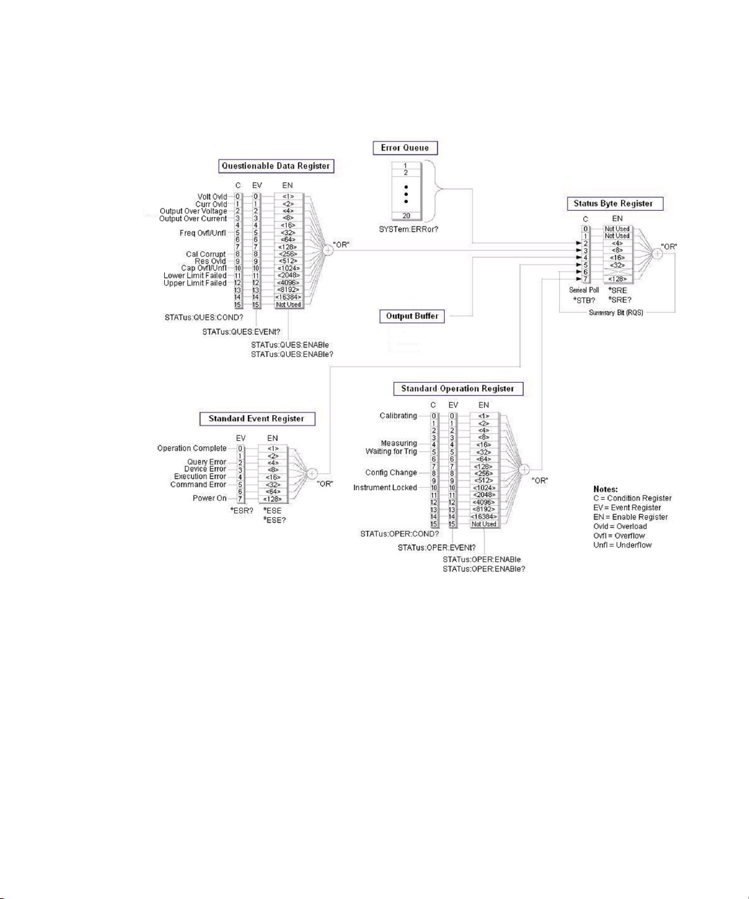
The relationship between various registers in the U3606A SCPI status
system is shown in Figure 1-1.
12 U3606A Programmer’s Reference
Page 27
Introduction to SCPI 1
SCPI Status System
Figure 1-1 Status system diagram
U3606A Programmer’s Reference 13
Page 28

1 Introduction to SCPI
NOTE
SCPI Status System
Standard Event register
The Standard Event register group reports the following types of
instrument events: power-on detected, command syntax errors, command
execution errors, device errors (self- test or calibration), or query errors.
All of these conditions can be reported in the Standard Event summary
bit through the enable register. To set the enable register mask, key in a
decimal value to the register using the event status enable (*ESE)
command.
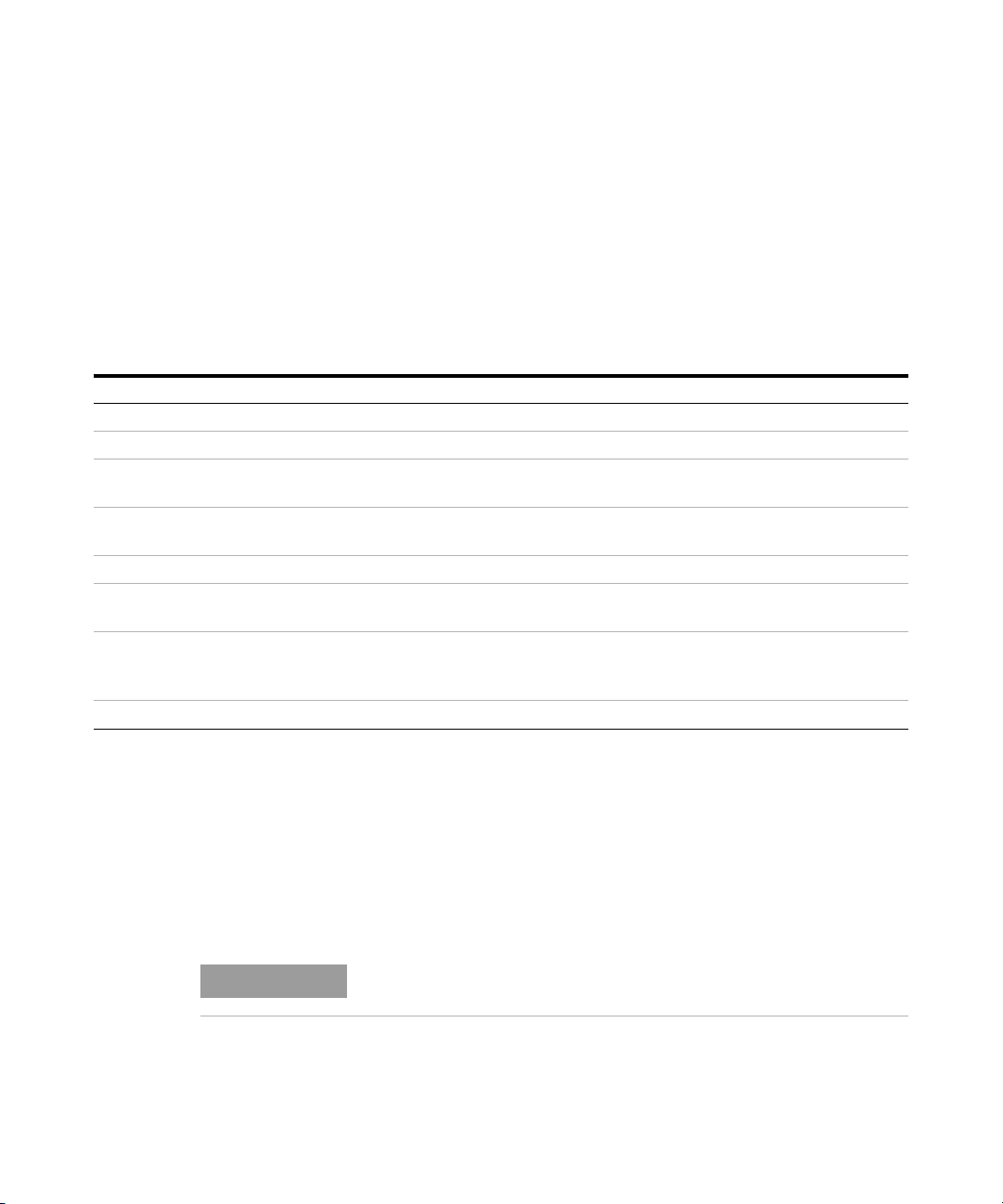
Bit definitions: Standard Event register
Bit number Decimal value Definition
0 Operation complete 1 All commands prior to and including *OPC have been executed.
1 Not used Not used “0” is returned.
2 Query error 4 A query error occurred (an error in the –400 range has been generated).
3 Device error 8 A self-test, calibration, or other device-specific error has occurred (an
error in the -300 range or any positive error has been generated).
4 Execution error 16 An execution error occurred.
5 Command error 32 A command syntax error occurred.
6 Not used Not used “0” is returned.
7 Power-on 128 Power has been turned off and on since the last time the event register
was read or cleared.
The event register in the Standard Event is cleared when:
• you execute the clear status (*CLS) command, or
• you read the event register using the event status register (*ESR?)
command.
The Standard Event enable register is cleared when you send the
*ESE 0 command.
When a command, execution, device, or query error have occurred, a
related error message will be generated. For a complete listing of all error
messages, refer to Chapter 16, “List of Error Messages,” starting on page
337.
14 U3606A Programmer’s Reference
Page 29
Introduction to SCPI 1
NOTE
SCPI Status System
Status Byte register
The Status Byte register group reports the conditions from the other
status registers. Clearing an event register from one of the other registers
will clear the corresponding bits in the Status Byte condition register.
Data that is waiting in the U3606A output buffer is immediately reported
on the “Message Available” bit (bit 4).
Bit definitions: Status Byte register
Bit number Decimal value Definition
0 Not used Not used “0” is returned.
1 Not used Not used “0” is returned.
2 Error queue 4 One or more errors have been stored in the Error Queue. Use the
SYSTem:ERRor? query to read and delete errors.
3 Questionable Data
summary
4 Message available 16 Data is available in the instrument output buffer.
5 Standard Event summary 32 One or more bits are set in the Standard Event register. Bits must be
6 Master Status summary 64 One or more bits are set in the Status Byte Register and may generate a
7 Not used Not used “0” is returned.
8 One or more bits are set in the Questionable Data register. Bits must be
enabled using the STATus:QUEStionable:ENABle command.
enabled using the *ESE command.
Request for Service (RQS). Bits must be enabled using the *SRE
command.
The Status Byte condition register will be cleared when:
• you execute the clear status (*CLS) command, or
• you read the event register from one of the other register groups. (Only
the corresponding bits are cleared in the condition register.)
The Status Byte enable register is cleared when you execute the *SRE 0
command.
Refer to Chapter 15, “IEEE-488.2 Common Commands,” starting on page
319 for more details of the common commands mentioned above.
U3606A Programmer’s Reference 15
Page 30
1 Introduction to SCPI
NOTE
SCPI Status System
Operation Status register
The operation status group monitors conditions which are a part of the
operation of the U3606A as a whole.
Bit definitions: Standard Operation register
Bit number Decimal value Definition
0 Calibration in progress 1 Instrument is performing a calibration.
1 Not used Not used “0” is returned.
2 Not used Not used “0” is returned.
3 Not used Not used “0” is returned.
4 Measuring 16 Instrument is initiated, and is making, or about to make a
measurement.
5 Waiting for trigger 32 Instrument is waiting for a trigger.
6 Not used Not used “0” is returned.
7 Not used Not used “0” is returned.
8 Configuration change 256 Instrument configuration has been changed, either from the front panel
or from the remote interface.
9 Not used Not used “0” is returned.
10 Instrument locked 1024 If a remote interface has a lock, this bit will be set. When a remote
interface releases the lock, this bit will be cleared.
11 Not used Not used “0” is returned.
12 Not used Not used “0” is returned.
13 Not used Not used “0” is returned.
14 Not used Not used “0” is returned.
15 Not used Not used “0” is returned.
Refer to Chapter 11, “STATus Subsystem,” starting on page 283 for more
details of the Operation Status register.
16 U3606A Programmer’s Reference
Page 31

Introduction to SCPI 1
NOTE
SCPI Status System
Questionable Status register
The questionable status register provides information about the quality of
the U3606A measurement results. Any or all of these conditions can be
reported in the questionable data summary bit through the enable register.
You must write a value using the STATus:QUEStionable:ENABle command
to set the enable register mask.
Bit definitions: Questionable Data register
Bit number Decimal value Definition
0 Voltage overload 1 Range overload on DC or AC voltage.
1 Current overload 2 Range overload on DC or AC current.
2 Output over voltage 4 Voltage output over protection limit.
3 Output over current 8 Current output over protection limit.
4 Not used Not used Instrument is initiated, and is making, or about to make a
measurement.
5 Frequency
overload/underflow
6 Not used Not used “0” is returned.
7 Not used Not used “0” is returned.
8 Calibration corrupt 256 At least one calibration constant is corrupt.
9 Resistance overload 512 Range overload on resistance.
10 Capacitance
overload/underflow
11 Lower limit failed 2048 Reading is less than lower limit in limit test.
12 Upper limit failed 4096 Reading is greater than upper limit in limit test.
13 Not used Not used “0” is returned.
14 Not used Not used “0” is returned.
15 Not used Not used “0” is returned.
32 Range overload or underflow on frequency.
1024 Range overload or underflow on capacitance.
Refer to Chapter 11, “STATus Subsystem,” starting on page 283 for more
details of the Questionable Status register.
U3606A Programmer’s Reference 17
Page 32

1 Introduction to SCPI
SCPI Status System
18 U3606A Programmer’s Reference
Page 33

U3606A Multimeter|DC Power Supply
Programmer’s Reference
2 CALCulate Subsystem
CALCulate:FUNCtion 20
CALCulate[:STATe] 23
CALCulate:AVERage:AVERage? 25
CALCulate:AVERage:COUNt? 26
CALCulate:AVERage:MAXimum? 27
CALCulate:AVERage:MINimum? 28
CALCulate:AVERage:PRESent? 29
CALCulate:DB:REFerence 30
CALCulate:DBM:REFerence 32
CALCulate:HOLD:VARiation 34
CALCulate:HOLD:THReshold 36
CALCulate:LIMit:LOWer 38
CALCulate:LIMit:UPPer 40
CALCulate:NULL:OFFSet 42
This chapter describes the CALCulate commands used to program the
U3606A over a remote interface. The U3606A is capable of performing
several mathematical, statistical, and limit calculation functions using the
CALCulate commands.
Page 34

2CALCulate Subsystem
CALCulate:FUNCtion
CALCulate:FUNCtion
Syntax
CALCulate:FUNCtion {AVERage|DB|DBM|HOLD|LIMit|NULL}
This command selects the calculation function to be used.
• AVERage: Returns the mathematical average of all readings taken since
averaging was enabled. Use CALCulate:AVERage:AVERage?,
CALCulate:AVERage:MAXimum?, CALCulate:AVERage:MINimum?,
CALCulate:AVERage:COUNt?, and CALCulate:AVERage:PRESent?
to return the average, maximum, minimum, count, and last reading
taken respectively, since averaging was enabled.
• DB: When enabled, the dB operation computes the dBm value for the
next reading, stores the dBm result into the dB Ref register and
immediately produces the following calculation. The first computed
reading is always precisely 00.000 dB.
Result = 10 × Log
[Reading2 / R
10
/ 0.001 W] – dB Ref
REF
Set a reference value in the dB reference register of the instrument
with the CALCulate:DB:REFerence command.
• DBM equation: Result = 10 × Log
Set the reference resistance (R
[Reading2 / R
10
) with the
REF
/ 0.001 W]
REF
CALCulate:DBM:REFerence command.
• HOLD: The reading hold feature allows you to capture and hold a stable
reading (refer to the U3606A User’s and Service Guide for details).
Set the variation and threshold values with the
CALCulate:HOLD:VARiation and CALCulate:HOLD:THReshold
commands.
• LIMit: Compares each reading against upper and lower limits. Limit
failures are posted in the Questionable Status register.
Set the upper and lower limits with CALCulate:LIMit:UPPer and
CALCulate:LIMit:LOWer, respectively. Check for limit failures with
the STATus:QUEStionable[:EVENt]? command.
• NULL equation: Result = Reading – Offset
Set the Offset using the CALCulate:NULL:OFFSet command
20 U3606A Programmer’s Reference
Page 35

CALCulate Subsystem 2
CALCulate:FUNCtion
CALCulate:FUNCtion?
This query returns a string value that represents the currently selected
calculation function: AVER, DB, DBM, HOLD, LIM, or NULL
Parameter
Item Type Description Default value
function Discrete AVERage|DB|DBM|HOLD|LIMit|NULL NULL
Remarks
• The CALCulate subsystem must be enabled using the
CALCulate:STATe command.
• All calculation functions are not allowed for diode and continuity tests.
• All calculation functions can be combined with each other with the
exception of the following restrictions:
• If DB and DBM are selected, all previously set calculation functions
will be disabled.
• If LIMit is selected, previously set AVERage and HOLD functions will
be disabled.
• If AVERage is selected, previously set LIMit and HOLD functions will
be disabled.
• If HOLD is selected, previously set LIMit and AVERage functions will
be disabled.
• If NULL is selected, previously set DBM and DB functions will be
disabled.
• The instrument clears the calculation function selection, reverting to the
default after a Factory Reset (*RST command) or an Instrument Preset
(SYSTem:PRESet command).
U3606A Programmer’s Reference 21
Page 36

2CALCulate Subsystem
CALCulate:FUNCtion
Example
& CALC:STAT ON
& CALC:FUNC DBM
& CALC:DBM:REF 300
& CALC:FUNC?
This command sets the calculation state to ON.
This command sets the function to be
calculated to DBM.
This command sets the dBm reference
resistance to 300 ohms.
This query returns the currently selected
calculation function.
$ DBM
See also
“CALCulate[:STATe]” on page 23
“STATus:QUEStionable[:EVENt]?” on page 292
“SYSTem:PRESet” on page 301
“*RST” on page 328
22 U3606A Programmer’s Reference
Page 37

CALCulate[:STATe]
Syntax
CALCulate[:STATe] {0|1|OFF|ON}
This command turns the CALCulate subsystem, and thus the selected
calculation function, on or off.
CALCulate[:STATe]?
This query returns a boolean value that represents the current calculation
state: 0 or 1
Parameter
Item Type Range of values Default value
state Boolean 0|1|OFF|ON 0
Remarks
CALCulate Subsystem 2
CALCulate[:STATe]
• This is an adjunct command to the CALCulate:FUNCtion command.
The calculation function to be used is selected using the
CALCulate:FUNCtion command.
• The CALCulate:STATe is set to OFF when the measurement function
is changed.
• When the CALCulate:STATe ON command is sent, the math registers
for null, averaging, and dB reference value are cleared. This also occurs
when the CALCulate:FUNCtion command is sent with the
CALCulate:STATe previously set to ON. The dBm reference resistance
value is not cleared in either case.
• The instrument resets the calculation state to off after a Factory Reset
(*RST command), an Instrument Preset (SYSTem:PRESet command), or
a function change.
U3606A Programmer’s Reference 23
Page 38

2CALCulate Subsystem
CALCulate[:STATe]
Example
& CALC ON
& CALC?
$ 1
See also
“CALCulate:FUNCtion” on page 20
“SYSTem:PRESet” on page 301
“*RST” on page 328
This command sets the calculation state to ON.
This query returns the current calculation state.
24 U3606A Programmer’s Reference
Page 39

CALCulate:AVERage:AVERage?
Syntax
CALCulate:AVERage:AVERage?
This query returns a numeric value that represents the mathematical
average (mean) of all readings taken since averaging was enabled.
Remarks
• This command returns the average of the readings taken, or “0” if there
is no data is available.
• The instrument clears the stored average data when averaging is
enabled, when the CALCulate:FUNCtion command is sent while
CALCulate:STATe is set to ON, after a power-on cycle, after a Factory
Reset (*RST command), an Instrument Preset (SYSTem:PRESet
command), or after a function change.
Example
CALCulate Subsystem 2
CALCulate:AVERage:AVERage?
& CALC:AVER:AVER?
$ +1.007850E+01
This query returns the average of the readings
taken.
See also
“CALCulate:FUNCtion” on page 20
“CALCulate[:STATe]” on page 23
“SYSTem:PRESet” on page 301
“SYSTem:SMOoth[:STATe]” on page 303
“*RST” on page 328
U3606A Programmer’s Reference 25
Page 40

2CALCulate Subsystem
CALCulate:AVERage:COUNt?
CALCulate:AVERage:COUNt?
Syntax
CALCulate:AVERage:COUNt?
This query returns a numeric value that represent the number of readings
taken since averaging was enabled.
Remarks
• This command returns the count since averaging was enabled, or “0” if
there is no data is available.
• The instrument clears the stored average data when averaging is
enabled, when the CALCulate:FUNCtion command is sent while
CALCulate:STATe is set to ON, after a power-on cycle, after a Factory
Reset (*RST command), an Instrument Preset (SYSTem:PRESet
command), or after a function change.
Example
& CALC:AVER:COUN?
$ +1.345000E+03
This query returns the number of readings
taken since averaging was enabled.
See also
“CALCulate:FUNCtion” on page 20
“CALCulate[:STATe]” on page 23
“SYSTem:PRESet” on page 301
“*RST” on page 328
26 U3606A Programmer’s Reference
Page 41

CALCulate:AVERage:MAXimum?
Syntax
CALCulate:AVERage:MAXimum?
This query returns a numeric value that represents the highest value
recorded since averaging was enabled.
Remarks
• This command returns the maximum value found, or “0” if there is no
data is available.
• The instrument clears the stored average data when averaging is
enabled, when the CALCulate:FUNCtion command is sent while
CALCulate:STATe is set to ON, after a power-on cycle, after a Factory
Reset (*RST command), an Instrument Preset (SYSTem:PRESet
command), or after a function change.
Example
CALCulate Subsystem 2
CALCulate:AVERage:MAXimum?
& CALC:AVER:MAX?
$ +1.007900E+01
This query returns the maximum value found.
See also
“CALCulate:FUNCtion” on page 20
“CALCulate[:STATe]” on page 23
“SYSTem:PRESet” on page 301
“*RST” on page 328
U3606A Programmer’s Reference 27
Page 42

2CALCulate Subsystem
CALCulate:AVERage:MINimum?
CALCulate:AVERage:MINimum?
Syntax
CALCulate:AVERage:MINimum?
This query returns a numeric value that represents the lowest value
recorded since averaging was enabled.
Remarks
• This command returns the minimum value found, or “0” if there is no
data is available.
• The instrument clears the stored average data when averaging is
enabled, when the CALCulate:FUNCtion command is sent while
CALCulate:STATe is set to ON, after a power-on cycle, after a Factory
Reset (*RST command), an Instrument Preset (SYSTem:PRESet
command), or after a function change.
Example
& CALC:AVER:MIN?
$ +1.007150E+01
This query returns the minimum value found.
See also
“CALCulate:FUNCtion” on page 20
“CALCulate[:STATe]” on page 23
“SYSTem:PRESet” on page 301
“*RST” on page 328
28 U3606A Programmer’s Reference
Page 43

CALCulate:AVERage:PRESent?
Syntax
CALCulate:AVERage:PRESent?
This query returns a numeric value that represents the last value recorded
since averaging was enabled.
Remarks
• This command returns the present reading taken, or “0” if there is no
data is available.
• The instrument clears the stored average data when averaging is
enabled, when the CALCulate:FUNCtion command is sent while
CALCulate:STATe is set to ON, after a power-on cycle, after a Factory
Reset (*RST command), an Instrument Preset (SYSTem:PRESet
command), or after a function change.
Example
CALCulate Subsystem 2
CALCulate:AVERage:PRESent?
& CALC:AVER:PRES?
$ +1.007870E+01
This query returns the last recorded value.
See also
“CALCulate:FUNCtion” on page 20
“CALCulate[:STATe]” on page 23
“SYSTem:PRESet” on page 301
“*RST” on page 328
U3606A Programmer’s Reference 29
Page 44
2CALCulate Subsystem
NOTE
CALCulate:DB:REFerence
CALCulate:DB:REFerence
Syntax
CALCulate:DB:REFerence <value>
This command stores a reference value in the dB reference register of the
instrument, which is used for the dB function in the
CALCulate:FUNCtion command.
You must select the dB math function (CALCulate:FUNCtion DB) and
turn on math operations (
dB reference register.
CALCulate:DB:REFerence?
This query returns a numeric value that represents the dB reference
value.
Parameter
CALCulate:STATe ON) before writing to the
Item Type Range of values Default value
value Numeric –120 dBm to 120 dBm 0 dBm
Remarks
The instrument clears the dB reference value to the default after a
Factory Reset (*RST command), an Instrument Preset (SYSTem:PRESet
command), or after a math or measurement function change.
30 U3606A Programmer’s Reference
Page 45

Example
CALCulate Subsystem 2
CALCulate:DB:REFerence
& CALC:DB:REF -10.0
& CALC:DB:REF?
$ -1.000000E+01
See also
“CALCulate:FUNCtion” on page 20
“CALCulate[:STATe]” on page 23
“SYSTem:PRESet” on page 301
“*RST” on page 328
This command sets the dB reference value to
–10.0 dBm.
This query returns the dB reference value.
U3606A Programmer’s Reference 31
Page 46

2CALCulate Subsystem
CALCulate:DBM:REFerence
CALCulate:DBM:REFerence
Syntax
CALCulate:DBM:REFerence <value>
This command selects the dBm reference resistance. This reference value
affects both the dBm and dB functions in the CALCulate:FUNCtion
command.
CALCulate:DBM:REFerence?
This query returns a numeric value that represents the dBm reference
resistance.
Parameter
Item Type Range of values Default value
value Numeric
[1]
Integers only. All decimal parts are truncated. For example, 60.7 ohms is truncated to 60 ohms.
[1]
1 ohm to 9999 ohms 600 ohms
Remarks
• The dBm reference resistance does not reset when calculation functions
are enabled by the CALCulate[:STATe] command, nor when the
CALCulate:FUNCtion command is sent with CALCulate:STATe set to
ON.
• The dBm reference resistance value is stored in the nonvolatile
memory. It is not affected by a power-on cycle, Factory Reset
(*RST command), Instrument Preset (SYSTem:PRESet command), or
function change.
32 U3606A Programmer’s Reference
Page 47

Example
CALCulate Subsystem 2
CALCulate:DBM:REFerence
& CALC:DBM:REF 300
& CALC:DBM:REF?
$ +3.000000E+02
See also
“CALCulate:FUNCtion” on page 20
“CALCulate[:STATe]” on page 23
“SYSTem:PRESet” on page 301
“*RST” on page 328
This command sets the dBm reference
resistance to 300 ohms.
This query returns the dBm reference
resistance.
U3606A Programmer’s Reference 33
Page 48

2CALCulate Subsystem
CALCulate:HOLD:VARiation
CALCulate:HOLD:VARiation
Syntax
CALCulate:HOLD:VARiation <value>
This command sets the variation of the hold function. When the variation
is set to 0, data hold is enabled. Otherwise, refresh hold is enabled.
CALCulate:HOLD:VARiation?
This command returns a numeric value that represents the variation of
the hold function.
Parameter
Item Type Range of values Default value
value Numeric 0% to 100% 10%
Remarks
• The hold variation does not reset when calculation functions are
enabled by the CALCulate[:STATe] command, nor when the
CALCulate:FUNCtion command is sent with CALCulate:STATe set to
ON.
• The hold variation value is stored in the nonvolatile memory. It is not
affected by a power-on cycle, Factory Reset (*RST command),
Instrument Preset (SYSTem:PRESet command), or function change.
Example
& CALC:HOLD:VAR 5
& CALC:HOLD:VAR?
$ +5.000000E+00
34 U3606A Programmer’s Reference
This command sets the hold variation to 5%.
This query returns the hold variation.
Page 49

See also
“CALCulate:FUNCtion” on page 20
“CALCulate[:STATe]” on page 23
“CALCulate:HOLD:THReshold” on page 36
“SYSTem:PRESet” on page 301
“*RST” on page 328
CALCulate Subsystem 2
CALCulate:HOLD:VARiation
U3606A Programmer’s Reference 35
Page 50

2CALCulate Subsystem
CALCulate:HOLD:THReshold
CALCulate:HOLD:THReshold
Syntax
CALCulate:HOLD:THReshold <value>
This command sets the threshold of the hold function.
CALCulate:HOLD:THReshold?
This query returns a numeric value that represents the threshold of the
hold function.
Parameter
Item Type Range of values Default value
value Numeric 0.1% to 9.9% 0.5%
Remarks
• The hold threshold does not reset when calculation functions are
enabled by the CALCulate[:STATe] command, nor when the
CALCulate:FUNCtion command is sent with CALCulate:STATe set to
ON.
• The hold threshold value is stored in the nonvolatile memory. It is not
affected by a power-on cycle, Factory Reset (*RST command),
Instrument Preset (SYSTem:PRESet command), or function change.
Example
& CALC:HOLD:THR 1
& CALC:HOLD:THR?
$ +1.000000E+00
36 U3606A Programmer’s Reference
This command sets the hold threshold to 1%.
This query returns the hold threshold.
Page 51

See also
“CALCulate:FUNCtion” on page 20
“CALCulate[:STATe]” on page 23
“CALCulate:HOLD:VARiation” on page 34
“SYSTem:PRESet” on page 301
“*RST” on page 328
CALCulate Subsystem 2
CALCulate:HOLD:THReshold
U3606A Programmer’s Reference 37
Page 52

2CALCulate Subsystem
NOTE
CALCulate:LIMit:LOWer
CALCulate:LIMit:LOWer
Syntax
CALCulate:LIMit:LOWer <value>
This command sets the lower limit for the present measurement function
(used in limit testing).
CALCulate:LIMit:LOWer?
This query returns a numeric value that represents the lower limit.
You must select the limit math function (CALCulate:FUNCtion LIMit)
and turn on math operations (
limit value.
Parameter
Item Type Range of values Default value
CALCulate:STATe ON) before you set a
value Numeric Dependant on measurement function
selected.
• VOLT:DC|AC|ACDC|DCAC:
–1200 V to 1200 V
• CURR:DC|AC|ACDC|DCAC:
–12 A to 12 A
• RES: –120e6 ohms to 120e6 ohms
• LRES: –12 ohms to 12 ohms
• CAP: –12e–3 F to 12e–3 F
• FREQ: –1.99999e6 Hz to 1.99999e6 Hz
• PWID: –1999.99e–3 s to 1999.99e–3 s
• DCYC: –100% to 100%
0
38 U3606A Programmer’s Reference
Page 53

CALCulate Subsystem 2
CALCulate:LIMit:LOWer
Remarks
• You can assign a lower limit, an upper limit, or both. The lower limit
must always be less than or equal to the upper limit, even if you are
using only one of the limits.
• Limit crossing: If a reading is less than the specified lower limit, bit 11
(Lower limit failed) is set in the Questionable Data register, which
results in an SRQ if enabled. You can use the
STATus:QUEStionable[:EVENt]? command to read the event
register. See Chapter 11, “STATus Subsystem,” starting on page 283 for
further information.
• Every measuring function has its own lower/upper limit registers. The
values are stored in the nonvolatile memory. It is not affected by a
power- on cycle, Factory Reset (*RST command), Instrument Preset
(SYSTem:PRESet command), or function change.
Example
& CALC:LIM:LOW -0.25
& CALC:LIM:LOW?
$ -2.500000E-01
This command sets the lower limit to –0.25.
This query returns the lower limit setting.
See also
“CALCulate:FUNCtion” on page 20
“CALCulate[:STATe]” on page 23
“CALCulate:LIMit:UPPer” on page 40
“STATus:QUEStionable[:EVENt]?” on page 292
“SYSTem:PRESet” on page 301
“*RST” on page 328
U3606A Programmer’s Reference 39
Page 54

2CALCulate Subsystem
NOTE
CALCulate:LIMit:UPPer
CALCulate:LIMit:UPPer
Syntax
CALCulate:LIMit:UPPer <value>
This command sets the upper limit for the present measurement function
(used in limit testing).
CALCulate:LIMit:UPPer?
This query returns a numeric value that represents the upper limit.
You must select the limit math function (CALCulate:FUNCtion LIMit)
and turn on math operations (
limit value.
Parameter
Item Type Range of values Default value
CALCulate:STATe ON) before you set a
value Numeric Dependant on measurement function
selected.
• VOLT:DC|AC|ACDC|DCAC:
–1200 V to 1200 V
• CURR:DC|AC|ACDC|DCAC:
–12 A to 12 A
• RES: –120e6 ohms to 120e6 ohms
• LRES: –12 ohms to 12 ohms
• CAP: –12e–3 F to 12e–3 F
• FREQ: –1.99999e6 Hz to 1.99999e6 Hz
• PWID: –1999.99e–3 to 1999.99e–3
• DCYC: –100 to 100
0
40 U3606A Programmer’s Reference
Page 55

CALCulate Subsystem 2
CALCulate:LIMit:UPPer
Remarks
• You can assign a lower limit, an upper limit, or both. The lower limit
must always be less than or equal to the upper limit, even if you are
using only one of the limits.
• Limit crossing: If a reading is less than the specified lower limit, bit 12
(Upper limit failed) is set in the Questionable Data register, which
results in an SRQ if enabled. You can use the
STATus:QUEStionable[:EVENt]? command to read the event
register. See Chapter 11, “STATus Subsystem,” starting on page 283 for
further information.
• Every measuring function has its own lower/upper limit registers. The
values are stored in the nonvolatile memory. It is not affected by a
power- on cycle, Factory Reset (*RST command), Instrument Preset
(SYSTem:PRESet command), or function change.
Example
& CALC:LIM:LOW 10.25
& CALC:LIM:LOW?
$ -2.500000E-01
This command sets the upper limit to 10.25.
This query returns the upper limit setting.
See also
“CALCulate:FUNCtion” on page 20
“CALCulate[:STATe]” on page 23
“CALCulate:LIMit:LOWer” on page 38
“STATus:QUEStionable[:EVENt]?” on page 292
“SYSTem:PRESet” on page 301
“*RST” on page 328
U3606A Programmer’s Reference 41
Page 56
2CALCulate Subsystem
NOTE
CALCulate:NULL:OFFSet
CALCulate:NULL:OFFSet
Syntax
CALCulate:NULL:OFFSet <value>
This command stores an offset value in the Null register of the
instrument.
CALCulate:NULL:OFFSet?
This query returns a numeric value that represents the offset value of the
Null calculation.
You must select the null math function (CALCulate:FUNCtion NULL)
and turn on math operations (
offset value.
Parameter
CALCulate:STATe ON) before you set an
Item Type Range of values Default value
value Numeric Dependant on measurement function
selected.
• VOLT:DC|AC|ACDC|DCAC:
–1200 V to 1200 V
• CURR:DC|AC|ACDC|DCAC:
–12 A to 12 A
• RES: –120e6 ohms to 120e6 ohms
• LRES: –12 ohms to 12 ohms
• CAP: –12e–3 F to 12e–3 F
• FREQ: –1.99999e6 Hz to 1.99999e6 Hz
• PWID: –1999.99e–3 s to 1999.99e–3 s
• DCYC: –100% to 100%
0
Remarks
The null offset value will reset after a power-on cycle, Factory Reset
(*RST command), Instrument Preset (SYSTem:PRESet command), or
function change.
42 U3606A Programmer’s Reference
Page 57

Example
CALCulate Subsystem 2
CALCulate:NULL:OFFSet
& CALC:NULL:OFFS 2.25
& CALC:NULL:OFFS?
$ 2.250000E+00
See also
“CALCulate:FUNCtion” on page 20
“CALCulate[:STATe]” on page 23
“SYSTem:PRESet” on page 301
“*RST” on page 328
This command sets the null value to 2.25.
This query returns the null value.
U3606A Programmer’s Reference 43
Page 58

2CALCulate Subsystem
CALCulate:NULL:OFFSet
44 U3606A Programmer’s Reference
Page 59

U3606A Multimeter|DC Power Supply
CAUTION
Programmer’s Reference
3 CALibration Subsystem
CALibration[:ALL]? 46
CALibration:COUNt? 47
CALibration:SECure:CODE 48
CALibration:SECure:STATe 49
CALibration:STRing 51
CALibration:VALue 53
CALibration:LEVel 55
Remote Calibration Procedures 56
Zero offset adjustments 57
Gain adjustments 59
Output adjustments 75
This chapter describes the CALibration commands used to program the
U3606A over a remote interface. The CALibration commands are used to
calibrate the U3606A.
For a more detailed discussion of the calibration procedures, see the
U3606A User's and Service Guide. Please refer to the U3606A User's and
Service Guide before attempting to calibrate the instrument. Improper use
of the CALibration commands can adversely affect the accuracy and
reliability of the instrument. A recommended sequence of calibration
commands is described in “Remote Calibration Procedures” on page 56.
Page 60

3 CALibration Subsystem
NOTE
CALibration[:ALL]?
CALibration[:ALL]?
Syntax
CALibration[:ALL]?
This query performs a calibration of the multimeter using the specified
calibration value (CALibration:VALue command) and returns a boolean
value that represents the calibration status: “+0” (calibration passed) or
“+1” (calibration failed).
Before you can calibrate the instrument, you must unsecure it by entering
the correct security code. See “CALibration:SECure:CODE” on page 48 for
more information on unsecuring the instrument for calibration.
Remarks
• If a calibration fails, “+1” is returned and an error is stored in the
error queue. For a complete listing of the error messages related to
calibration failures, see Chapter 16, “List of Error Messages,” starting
on page 337.
• This command increments the calibration count on the U3606A (see
CALibration:COUNt? command).
Example
& CAL?
$ +0
This command performs a calibration and
returns a pass/fail indication.
See also
“CALibration:SECure:CODE” on page 48
“CALibration:VALue” on page 53
46 U3606A Programmer’s Reference
Page 61

CALibration:COUNt?
Syntax
CALibration:COUNt?
This query returns a numeric value that represents the calibration count
indicating how many calibrations have been performed in the instrument.
Note that your instrument was calibrated before it left the factory. When
you receive your instrument, be sure to read the count to determine the
initial values.
Remarks
• The calibration counts increment up to a maximum of 32767 after
which they roll over to “0”. Since the value increments by one for each
calibration point, a complete calibration may increase the value by
many counts.
• The calibration count is incremented by the CALibration[:ALL]?
command. You can read the calibration count whether the instrument is
secured or unsecured.
• The calibration count is stored in nonvolatile memory, and does not
change when power has been off or after a Factory Reset (*RST
command).
CALibration Subsystem 3
CALibration:COUNt?
Example
& CAL:COUN?
$ +739
This command returns the calibration count.
See also
“CALibration[:ALL]?” on page 46
“CALibration:SECure:CODE” on page 48
U3606A Programmer’s Reference 47
Page 62

3 CALibration Subsystem
CALibration:SECure:CODE
CALibration:SECure:CODE
Syntax
CALibration:SECure:CODE <new_code>
This command allows you to enter a new security code to prevent
accidental or unauthorized calibrations. The specified code is used to
unsecure calibration memory. To change the security code, you must first
unsecure calibration memory using the old security code, and then enter a
new code.
Parameter
Item Type Range of values Default value
new_code String A string of up to 12 characters.
[1]
You do not have to use all 12 characters but the first character must always be a letter (A to Z). The
remaining 11 characters can be letters (A to Z) or numbers (0 to 9). Blank spaces are not allowed.
[1]
Remarks
ATU3606A
• The security code is set to ATU3606A when the instrument is shipped
from the factory.
• If you forget your security code, you can override the security feature.
See the U3606A User’s and Service Guide for more information.
• See the U3606A User’s and Service Guide for more information on how
to unlock the instrument from the front panel.
• The security code is stored in nonvolatile memory, and does not change
when power has been off or after a Factory Reset (*RST command).
Example
& CAL:SEC:CODE ABC1234
This command sets a new calibration security
code (the calibration memory must be
unsecured first).
See also
“CALibration:SECure:STATe” on page 49
48 U3606A Programmer’s Reference
Page 63

CALibration:SECure:STATe
Syntax
CALibration:SECure:STATe <mode>, <code>
This command unsecures or secures the instrument for calibration. To
unsecure the instrument, you must provide a security code to prevent
accidental or unauthorized calibrations of the instrument. Before you can
calibrate the instrument, you must unsecure it by entering the correct
security code.
CALibration:SECure:STATe?
This query returns a boolean value that represents the current calibration
security setting: 0 or 1
Parameters
Item Type Range of values Default value
mode Boolean 0|1|OFF|ON 0
code String A string of up to 12 characters.
[1]
You do not have to use all 12 characters but the first character must always be a letter (A to Z). The
remaining 11 characters can be letters, numbers (0 to 9), or the underscore character (“_”). Blank
spaces are not allowed.
CALibration Subsystem 3
CALibration:SECure:STATe
[1]
This
parameter is required to disable security, but
is optional to enable security (but must be
correct if provided).
ATU3606A
Remarks
• When you first receive your instrument, it is secured. The security code
is set to ATU3606A when the instrument is shipped from the factory.
• Once you enter a security code, that code must be used for both
front- panel and remote-interface calibration. For example, if you secure
the instrument from the front panel, you must use that same code to
unsecure it from the remote interface.
• Unsecuring the instrument using this command enables the instrument
to be calibrated. To calibrate the U3606A, use the CALibration:VALue
and CALibration[:ALL]? commands.
U3606A Programmer’s Reference 49
Page 64

3 CALibration Subsystem
CALibration:SECure:STATe
• The calibration security setting is stored in nonvolatile memory, and
does not change when power has been off or after a Factory Reset
(*RST command).
Example
& CAL:SEC:STAT OFF,
ATU3606A
& CAL:SEC:STAT?
$ 0
See also
“CALibration:SECure:CODE” on page 48
This command unsecures the instrument using
the factory default security code.
This query returns the current calibration
security setting.
50 U3606A Programmer’s Reference
Page 65

CALibration:STRing
Syntax
CALibration:STRing "<string>"
This command allows you to store one message in calibration memory. For
example, you can store such information as the date when the last
calibration was performed, the date when the next calibration is due, the
instrument's serial number, or even the name and phone number of the
person to contact for a new calibration.
CALibration:STRing?
This query returns an ASCII string value enclosed in double quotes. If no
calibration message has been specified, an empty quoted string ("") is
returned.
Parameter
Item Type Range of values Default value
CALibration Subsystem 3
CALibration:STRing
string String A string of up to 40 characters enclosed in
[1]
You can use letters (A to Z), numbers (0 to 9), and special characters like “@”, “%”, “*”, and so on.
quotes
[1]
-
Remarks
• You can record a calibration message only from the remote interface
and only when the instrument is unsecured
(CALibration:SECure:STATe OFF command). You can read the
message from the remote interface only. You can read the calibration
message whether the instrument is secured or unsecured.
• Storing a calibration message will overwrite any message previously
stored in memory.
• The calibration message is stored in nonvolatile calibration memory,
and does not change when power has been off or after a Factory Reset
(*RST command).
U3606A Programmer’s Reference 51
Page 66

3 CALibration Subsystem
CALibration:STRing
Example
& CAL:STR "CAL: 27 Nov
2009"
& CAL:STR?
$ "CAL: 27 Nov 2009"
See also
“CALibration:SECure:CODE” on page 48
This command stores a message in the
calibration memory.
This query returns the message currently
stored in calibration memory (the quotes are
also returned).
52 U3606A Programmer’s Reference
Page 67

CALibration:VALue
Syntax
CALibration:VALue <value>
This command specifies the value of the known calibration signal as
outlined in the calibration procedures in the U3606A User’s and Service
Guide.
CALibration:VALue?
This query returns a numeric value that represents the calibration value.
Parameter
Item Type Range of values Default value
CALibration Subsystem 3
CALibration:VALue
value Numeric Desired calibration signal in the units
specified by the present measurement
function.
-
Remarks
Refer to the U3606A User’s and Service Guide for detailed procedures,
including how to connect a calibration source, recommended equipment,
the specified calibration points, and so forth.
U3606A Programmer’s Reference 53
Page 68

3 CALibration Subsystem
CALibration:VALue
Example
& CONF:VOLT:DC
& CAL:VAL 10
& CAL:VAL?
$ +1.000000E+01
See also
“CALibration[:ALL]?” on page 46
This command configures the instrument for
DC voltage measurements.
This command sets calibration value to
+10 volts for DC voltage measurements.
This query returns the present calibration
value.
54 U3606A Programmer’s Reference
Page 69

CALibration:LEVel
CALibration:LEVel {MINimum|MAXimum|LOAD}
This command selects the minimum or maximum calibration point as
outlined in the calibration procedures in the U3606A User’s and Service
Guide.
Parameter
Item Type Range of values Default value
level Discrete MINimum|MAXimum|LOAD -
Remarks
Refer to the U3606A User’s and Service Guide for detailed procedures,
including how to set up the output calibration connections, the specified
calibration points, how to initiate the calibration of the output voltage or
current, and so forth.
CALibration Subsystem 3
CALibration:LEVel
Example
& SOUR:VOLT:RANG 8
& CAL:LEV MAX
U3606A Programmer’s Reference 55
This command sets the current output range to
S2 (8 V/3 A).
This command sets calibration point to 8 V.
Page 70

3 CALibration Subsystem
Remote Calibration Procedures
Remote Calibration Procedures
The CALibration commands are used to calibrate the U3606A. Please note
that the use of these commands requires a detailed knowledge of the
appropriate calibration procedures, which are described in the U3606A
User’s and Service Guide. Please refer to that guide before attempting to
calibrate the instrument. Improper use of the CALibration commands can
adversely affect the accuracy and reliability of the instrument.
During calibration the following instrument behavior is expected:
• The display “CALib” in the lower secondary display starts flashing to
indicate that the calibration is in progress.
• Successful completion of the adjustment is indicated by a short beep
and the primary display briefly showing “PASS”.
• An adjustment failure is indicated by a long beep, the primary display
showing “FAiL” and a calibration error number appearing in the upper
secondary display. Correct the problem and repeat this procedure.
The adjustment data is stored only when all the calibration items for the
measurement selected is completed. For example, to store the adjustment
data for DC voltage measurements, you will need to complete the following
calibration items: Short, 100 mV, 1 V, –1 V, 10 V, 100 V, and 1000 V.
Before performing and adjustments, first you will need to unsecure the
instrument for calibration.
Calibration steps Remote commands
1 Enter the calibration mode.
& CAL:SEC:STAT OFF,
ATU3606A
2 Optional step: Change the default security
code after unsecuring the instrument for
calibration (be sure to write down the new
code).
3 Perform the zero and gain adjustments for
the front input terminals. See page 57.
4 Perform the output adjustments for the front
and rear output terminals. See page 75.
& CAL:SEC:CODE <new code>
56 U3606A Programmer’s Reference
Page 71
CALibration Subsystem 3
CAUTION
Remote Calibration Procedures
Zero offset adjustments
Each time you perform a zero offset adjustment, the instrument stores a
new set of offset correction constants for measurement functions and
ranges. The instrument will sequence through all required functions and
ranges automatically and store new zero offset calibration constants.
Never turn off the instrument during zero offset adjustment. This may
cause ALL calibration memory to be lost.
Be sure to allow the instrument to warm up and stabilize for 2 hours
before performing the adjustments. Follow the steps outlined below.
Review the “Test Considerations” described in the U3606A User’s and
Service Guide before beginning this test.
Calibration step Remote command
Zero offset adjustment — DC voltage (short)
U3606A Programmer’s Reference 57
1 Select the DC voltage measurement.
Connect a shorting plug between the V (red)
and LO (black) input terminals.
2 Calibrate the zero point for DC voltage
measurements.
3 Start the calibration.
Zero offset adjustment — 2-wire resistance (short)
4 Select the 2-wire resistance measurement.
Leave the shorting plug between the Ω (red)
and LO (black) input terminals connected.
5 Calibrate the zero point for 2-wire resistance
measurements.
6 Start the calibration.
& CONF:VOLT:DC
& CAL:VAL 0
& CAL?
& CONF:RES
& CAL:VAL 0
& CAL?
Page 72
3 CALibration Subsystem
Remote Calibration Procedures
Calibration step Remote command
Zero offset adjustment — 2-wire resistance (open)
7 Remove the shorting plug from the input
terminals (all terminals open). Select the
2-wire resistance measurement, 100 MΩ
range.
8 Calibrate the open point for 2-wire
resistance measurements.
9 Start the calibration.
Zero offset adjustment — DC current (open)
10 Select the DC current measurement. Leave
the input terminals open.
11 Calibrate the open point for DC current
measurements.
12 Start the calibration.
Zero offset adjustment — Capacitance (open)
13 Select the capacitance measurement. Leave
the input terminals open.
14 Calibrate the open point for capacitance
measurements.
15 Start the calibration.
& CONF:RES 100M
& CAL:VAL 9.9E+37
& CAL?
& CONF:CURR
& CAL:VAL 9.9E+37
& CAL?
& CONF:CAP
& CAL:VAL 9.9E+37
& CAL?
58 U3606A Programmer’s Reference
Page 73

CALibration Subsystem 3
CAUTION
Remote Calibration Procedures
Gain adjustments
The instrument calculates and stores gain corrections for each input value.
The gain constant is computed from the calibration value entered for the
calibration command and from measurements made automatically during
the adjustment procedure.
Most measuring functions and ranges have gain adjustment procedures.
The 100 MΩ range does not have gain calibration procedures.
Adjustments for each function should be performed ONLY in the order
shown.
Gain adjustment considerations
• The zero offset adjustment procedure must have been recently
performed prior to beginning any gain adjustment procedures.
• Be sure to allow the instrument to warm up and stabilize for 2 hours
before performing the adjustments.
• Consider the thermal effects as you are connecting test leads to the
calibrator and instrument. It is recommended to wait 1 minute before
starting the calibration after connecting the test leads.
U3606A Programmer’s Reference 59
Never turn off the instrument during a gain adjustment. This may
cause the calibration memory for the present function to be lost.
Page 74
3 CALibration Subsystem
NOTE
If the zero offset adjustment procedure has been recently
performed prior to the DC voltage gain calibration procedure, the
adjustment item “Short” can be omitted.
Remote Calibration Procedures
DC voltage gain adjustment procedure
Follow the steps outlined below. Review the “Test Considerations”
described in the U3606A User’s and Service Guide and the “Gain
adjustment considerations” on page 59 before beginning this test.
Calibration step Remote command
DC voltage gain adjustment — Short
1 Select the DC voltage measurement.
Connect a shorting plug between the V (red)
and LO (black) input terminals.
2 Calibrate the zero point for DC voltage
measurements.
3 Start the calibration.
DC voltage gain adjustment — 100 mV
4 Select the 100 mV range. Remove the
shorting plug from the input terminals. Input
100 mV DC voltage to the V (red) and
LO (black) input terminals.
5 Calibrate the 100 mV point for DC voltage
measurements.
6 Start the calibration.
DC voltage gain adjustment — ±1 V
& CONF:VOLT:DC
& CAL:VAL 0
& CAL?
& CONF:VOLT:DC 0.1
& CAL:VAL 0.1
& CAL?
7 Select the 1 V range. Input 1 V DC voltage to
the V (red) and LO (black) input terminals.
8 Calibrate the 1 V point for DC voltage
measurements.
9 Start the calibration.
60 U3606A Programmer’s Reference
& CONF:VOLT:DC 1
& CAL:VAL 1
& CAL?
Page 75
Remote Calibration Procedures
Calibration step Remote command
CALibration Subsystem 3
10 Calibrate the –1 V point for DC voltage
measurements.
11 Start the calibration.
DC voltage gain adjustment — 10 V
12 Select the 10 V range. Input 10 V DC voltage
to the V (red) and LO (black) input terminals.
13 Calibrate the 10 V point for DC voltage
measurements.
14 Start the calibration.
DC voltage gain adjustment — 100 V
15 Select the 100 V range. Input 100 V DC
voltage to the V (red) and LO (black) input
terminals.
16 Calibrate the 100 V point for DC voltage
measurements.
17 Start the calibration.
DC voltage gain adjustment — 1000 V
18 Select the 1000 V range. Input 1000 V DC
voltage to the V (red) and LO (black) input
terminals.
& CAL:VAL -1
& CAL?
& CONF:VOLT:DC 10
& CAL:VAL 10
& CAL?
& CONF:VOLT:DC 100
& CAL:VAL 100
& CAL?
& CONF:VOLT:DC 1000
19 Calibrate the 1000 V point for DC voltage
measurements.
20 Start the calibration.
& CAL:VAL 1000
& CAL?
U3606A Programmer’s Reference 61
Page 76
3 CALibration Subsystem
Remote Calibration Procedures
AC voltage gain adjustment procedure
Follow the steps outlined below. Review the “Test Considerations”
described in the U3606A User’s and Service Guide and the “Gain
adjustment considerations” on page 59 before beginning this test.
Calibration step Remote command
AC voltage gain adjustment — 10 mV
1 Select the AC voltage measurement, 10 mV
range. Input 10 mV, 1 kHz AC voltage to the
V (red) and LO (black) input terminals.
2 Calibrate the 10 mV point for AC voltage
measurements.
3 Start the calibration.
AC voltage gain adjustment — 100 mV
4 Select the 100 mV range. Input 100 mV,
1 kHz AC voltage to the V (red) and LO
(black) input terminals.
5 Calibrate the 100 mV point for AC voltage
measurements.
6 Start the calibration.
AC voltage gain adjustment — 1 V
7 Select the 1 V range. Input 1 V, 1 kHz AC
voltage to the V (red) and LO (black) input
terminals.
8 Calibrate the 1 V point for AC voltage
measurements.
9 Start the calibration.
& CONF:VOLT:AC 0.01
& CAL:VAL 0.01
& CAL?
& CONF:VOLT:AC 0.1
& CAL:VAL 0.1
& CAL?
& CONF:VOLT:AC 1
& CAL:VAL 1
& CAL?
62 U3606A Programmer’s Reference
Page 77
Remote Calibration Procedures
Calibration step Remote command
AC voltage gain adjustment — 10 V
CALibration Subsystem 3
10 Select the 10 V range. Input 10 V, 1 kHz AC
voltage to the V (red) and LO (black) input
terminals.
11 Calibrate the 10 V point for AC voltage
measurements.
12 Start the calibration.
AC voltage gain adjustment — 100 V
13 Select the 100 V range. Input 100 V, 1 kHz
AC voltage to the V (red) and LO (black)
input terminals.
14 Calibrate the 100 V point for AC voltage
measurements.
15 Start the calibration.
AC voltage gain adjustment — 750 V
16 Select the 750 V range. Input 750 V, 1 kHz
AC voltage to the V (red) and LO (black)
input terminals.
17 Calibrate the 750 V point for AC voltage
measurements.
18 Start the calibration.
& CONF:VOLT:AC 10
& CAL:VAL 10
& CAL?
& CONF:VOLT:AC 100
& CAL:VAL 100
& CAL?
& CONF:VOLT:AC 750
& CAL:VAL 750
& CAL?
U3606A Programmer’s Reference 63
Page 78
3 CALibration Subsystem
Remote Calibration Procedures
Frequency gain adjustment procedure
Follow the steps outlined below. Review the “Test Considerations”
described in the U3606A User’s and Service Guide and the “Gain
adjustment considerations” on page 59 before beginning this test.
Calibration step Remote command
Frequency gain adjustment — 1 kHz
1 Select the AC voltage measurement, 1 V
range.
2 Select the frequency measurement. Input
1 V, 1 kHz AC voltage to the V (red) and
LO (black) input terminals.
3 Calibrate the 1 kHz point for frequency
measurements.
4 Start the calibration.
& CONF:VOLT:AC 1
& CONF:FREQ
& CAL:VAL 1000
& CAL?
64 U3606A Programmer’s Reference
Page 79
CALibration Subsystem 3
NOTE
If the zero offset adjustment procedure has been recently
performed prior to the resistance gain calibration procedure, the
adjustment item “Short” and “Open” can be omitted.
Remote Calibration Procedures
Resistance gain adjustment procedures
Follow the steps outlined below. Review the “Test Considerations”
described in the U3606A User’s and Service Guide and the “Gain
adjustment considerations” on page 59 before beginning this test.
Calibration step Remote command
Resistance gain adjustment — Short
1 Select the 2-wire resistance measurement.
Connect a shorting plug between the Ω
(red) and LO (black) input terminals.
2 Calibrate the zero point for 2-wire resistance
measurements.
3 Start the calibration.
Resistance gain adjustment — Open
4 Remove the shorting plug from the input
terminals (all terminals open). Select the
100 MΩ range.
5 Calibrate the open point for 2-wire
resistance measurements.
6 Start the calibration.
Resistance gain adjustment — 10 MΩ
7 Select the 10 MΩ range. Input 10 MΩ
resistance to the Ω (red) and LO (black)
input terminals.
& CONF:RES
& CAL:VAL 0
& CAL?
& CONF:RES 100M
& CAL:VAL 9.9E+37
& CAL?
& CONF:RES 10M
8 Calibrate the 10 MΩ point for 2-wire
resistance measurements.
9 Start the calibration.
U3606A Programmer’s Reference 65
& CAL:VAL 10M
& CAL?
Page 80
3 CALibration Subsystem
Remote Calibration Procedures
Calibration step Remote command
Resistance gain adjustment — 1 MΩ
10 Select the 1 MΩ range. Input 1 MΩ
resistance to the Ω (red) and LO (black)
input terminals.
11 Calibrate the 1 MΩ point for 2-wire
resistance measurements.
12 Start the calibration.
Resistance gain adjustment — 100 kΩ
13 Select the 100 kΩ range. Input 100 kΩ
resistance to the Ω (red) and LO (black)
input terminals.
14 Calibrate the 100 kΩ point for 2-wire
resistance measurements.
15 Start the calibration.
Resistance gain adjustment — 10 kΩ
16 Select the 10 kΩ range. Input 10 kΩ
resistance to the Ω (red) and LO (black)
input terminals.
17 Calibrate the 10 kΩ point for 2-wire
resistance measurements.
18 Start the calibration.
& CONF:RES 1M
& CAL:VAL 1M
& CAL?
& CONF:RES 100k
& CAL:VAL 100k
& CAL?
& CONF:RES 10k
& CAL:VAL 10k
& CAL?
Resistance gain adjustment — 1000 Ω
19 Select the 1000 Ω range. Input 1000 Ω
resistance to the Ω (red) and LO (black)
input terminals.
20 Calibrate the 1000 Ω point for 2-wire
resistance measurements.
21 Start the calibration.
& CONF:RES 1000
& CAL:VAL 1000
& CAL?
66 U3606A Programmer’s Reference
Page 81
Remote Calibration Procedures
Calibration step Remote command
Resistance gain adjustment — 100 Ω
CALibration Subsystem 3
22 Select the 100 Ω range. Input 100 Ω
resistance to the Ω (red) and LO (black)
input terminals.
23 Calibrate the 100 Ω point for 2-wire
resistance measurements.
24 Start the calibration.
& CONF:RES 100
& CAL:VAL 100
& CAL?
U3606A Programmer’s Reference 67
Page 82
3 CALibration Subsystem
NOTE
If the zero offset adjustment procedure has been recently
performed prior to the current gain calibration procedure, the
adjustment item “Open” can be omitted.
Remote Calibration Procedures
DC current gain adjustment procedure
Follow the steps outlined below. Review the “Test Considerations”
described in the U3606A User’s and Service Guide and the “Gain
adjustment considerations” on page 59 before beginning this test.
Calibration step Remote command
DC current gain adjustment — Open
1 Remove all connections from the input
terminals (all terminals open). Select the DC
current measurement.
2 Calibrate the open point for DC current
measurements.
3 Start the calibration.
DC current gain adjustment — 10 mA
4 Select the 10 mA range. Input 10 mA DC
current to the I (red) and LO (black) input
terminals.
5 Calibrate the 10 mA point for DC current
measurements.
6 Start the calibration.
DC current gain adjustment — 100 mA
7 Select the 100 mA range. Input 100 mA DC
current to the I (red) and LO (black) input
terminals.
& CONF:CURR:DC
& CAL:VAL 9.9E+37
& CAL?
& CONF:CURR:DC 0.01
& CAL:VAL 0.01
& CAL?
& CONF:CURR:DC 0.1
8 Calibrate the 100 mA point for DC current
measurements.
9 Start the calibration.
68 U3606A Programmer’s Reference
& CAL:VAL 0.1
& CAL?
Page 83
Remote Calibration Procedures
Calibration step Remote command
DC current gain adjustment — 1 A
CALibration Subsystem 3
10 Select the 1 A range. Input 1 A DC current to
the I (red) and LO (black) input terminals.
11 Calibrate the 1 A point for DC current
measurements.
12 Start the calibration.
& CONF:CURR:DC 1
& CAL:VAL 1
& CAL?
U3606A Programmer’s Reference 69
Page 84
3 CALibration Subsystem
Remote Calibration Procedures
AC current gain adjustment procedure
Follow the steps outlined below. Review the “Test Considerations”
described in the U3606A User’s and Service Guide and the “Gain
adjustment considerations” on page 59 before beginning this test.
Calibration steps Remote commands
AC current gain adjustment — 1 mA
1 Select the AC current measurement, 1 mA
range. Input 1 mA, 1 kHz AC current to the
I (red) and LO (black) input terminals.
2 Calibrate the 1 mA point for AC current
measurements.
3 Start the calibration.
AC current gain adjustment — 10 mA
4 Select the 10 mA range. Input 10 mA, 1 kHz
AC current to the I (red) and LO (black) input
terminals.
5 Calibrate the 10 mA point for AC current
measurements.
6 Start the calibration.
AC current gain adjustment — 100 mA
7 Select the 100 mA range. Input 100 mA,
1 kHz AC current to the I (red) and LO (black)
input terminals.
8 Calibrate the 100 mA point for AC current
measurements.
9 Start the calibration.
& CONF:CURR:AC 0.001
& CAL:VAL 0.001
& CAL?
& CONF:CURR:AC 0.01
& CAL:VAL 0.01
& CAL?
& CONF:CURR:AC 0.1
& CAL:VAL 0.1
& CAL?
70 U3606A Programmer’s Reference
Page 85
CALibration Subsystem 3
Remote Calibration Procedures
Calibration steps Remote commands
AC current gain adjustment — 1 A
10 Select the 1 A range. Input 1 A, 1 kHz AC
current to the I (red) and LO (black) input
terminals.
11 Calibrate the 1 A point for AC current
measurements.
12 Start the calibration.
& CONF:CURR:AC 1
& CAL:VAL 1
& CAL?
U3606A Programmer’s Reference 71
Page 86
3 CALibration Subsystem
NOTE
If the zero offset adjustment procedure has been recently
performed prior to the capacitance gain calibration procedure, the
adjustment item “Open” can be omitted.
Remote Calibration Procedures
Capacitance gain adjustment procedure
Follow the steps outlined below. Review the “Test Considerations”
described in the U3606A User’s and Service Guide and the “Gain
adjustment considerations” on page 59 before beginning this test.
Calibration steps Remote commands
Capacitance gain adjustment — Open
1 Remove all connections from the input
terminals (all terminals open). Select the
capacitance measurement.
2 Calibrate the open point for capacitance
measurements.
3 Start the calibration.
Capacitance gain adjustment — 0.4 nF
4 Select the 1 nF range. Input 0.4 nF to the
(red) and LO (black) input terminals.
5 Calibrate the 0.4 nF point for capacitance
measurements.
6 Start the calibration.
Capacitance gain adjustment — 1 nF
7 Input 1 nF to the (red) and LO (black)
input terminals.
& CONF:CAP
& CAL:VAL 9.9E+37
& CAL?
& CONF:CAP 1n
& CONF:VAL 0.4E-9
& CAL?
8 Calibrate the 1nF point for capacitance
measurements.
9 Start the calibration.
72 U3606A Programmer’s Reference
& CONF:VAL 1E-9
& CAL?
Page 87
CALibration Subsystem 3
Remote Calibration Procedures
Calibration steps Remote commands
Capacitance gain adjustment — 10 nF
10 Select the 10 nF range. Input 10 nF to the
(red) and LO (black) input terminals.
11 Calibrate the 10 nF point for capacitance
measurements.
12 Start the calibration.
Capacitance gain adjustment — 100 nF
13 Select the 100 nF range. Input 100 nF to the
(red) and LO (black) input terminals.
14 Calibrate the 100 nF point for capacitance
measurements.
15 Start the calibration.
Capacitance gain adjustment — 1 μF
16 Select the 1 μF range. Input 1 μF to the
(red) and LO (black) input terminals.
17 Calibrate the 1 μF point for capacitance
measurements.
18 Start the calibration.
Capacitance gain adjustment — 10 μF
19 Select the 10 μF range. Input 10 μF to the
(red) and LO (black) input terminals.
& CONF:CAP 10n
& CONF:VAL 1E-8
& CAL?
& CONF:CAP 100n
& CONF:VAL 1E-7
& CAL?
& CONF:CAP 1u
& CONF:VAL 1E-6
& CAL?
& CONF:CAP 10u
20 Calibrate the 10 μF point for capacitance
measurements.
21 Start the calibration.
Capacitance gain adjustment — 100 μF
22 Select the 100 μF range. Input 100 μF to the
(red) and LO (black) input terminals.
23 Calibrate the 100 μF point for capacitance
measurements.
24 Start the calibration.
& CONF:VAL 1E-5
& CAL?
& CONF:CAP 100u
& CONF:VAL 1E-4
& CAL?
U3606A Programmer’s Reference 73
Page 88
3 CALibration Subsystem
Remote Calibration Procedures
Calibration steps Remote commands
Capacitance gain adjustment — 1 mF
25 Select the 1 mF range. Input 1 mF to the
(red) and LO (black) input terminals.
26 Calibrate the 1 mF point for capacitance
measurements.
27 Start the calibration.
Capacitance gain adjustment — 10 mF
28 Select the 10 mF range. Input 10 mF to the
(red) and LO (black) input terminals.
29 Calibrate the 10 mF point for capacitance
measurements.
30 Start the calibration.
& CONF:CAP 1m
& CONF:VAL 1E-3
& CAL?
& CONF:CAP 10m
& CONF:VAL 1E-2
& CAL?
74 U3606A Programmer’s Reference
Page 89

CALibration Subsystem 3
Remote Calibration Procedures
Output adjustments
The instrument calculates and stores output corrections for each output
level. The U3606A implements a closed loop output calibration procedure
to its inherent dual function ability as a digital multimeter and a DC
power supply. The output constant is computed from the calibration level
set for the calibration command and from measurements made
automatically during the adjustment procedure.
Calibration steps Remote commands
1 Place the instrument in the free-run mode.
Measurements are made continuously and
the readings are stored in the instrument
memory.
2 Set the signal source to read the sense
signal inputs from the front output terminals
of the instrument. The U3606A needs to be
calibrated twice. Once for the internal sense
source and again for the external sense
source.
3 Perform the current and voltage output
adjustments for the front output terminals.
See page 76.
4 Set the signal source to read the sense
signal inputs from the rear output terminals
of the instrument. When you have
completed the voltage and current output
adjustments for the internal sense source,
repeat the entire adjustment procedure
again for the external sense source.
5 Perform current and voltage output
adjustments for the rear output terminals.
See page 76.
6 Remove all connections from the
instrument. Reset the calibration message
and record the new calibration count.
& INIT:CONT ON
& SOUR:SENS INT
& SOUR:SENS EXT
& CAL:STR "<new_message>"
& CAL:COUN?
Adjustments for each function should be performed ONLY in the order
shown.
U3606A Programmer’s Reference 75
Page 90
3 CALibration Subsystem
Remote Calibration Procedures
Follow the steps outlined below. Review the “Test Considerations”
described in the U3606A User’s and Service Guide before beginning this
test.
Calibration steps Remote commands
Current output adjustment — S2 (8 V/3 A) range
1 Connect the (red) and (black) output
terminals to the I (red) and LO (black) input
terminals.
2 Select the CC output, 3 A range.
3 Calibrate the lower point for CC output.
4 Calibrate the upper point for CC output.
Current output adjustment — S1 (30 V/1 A) range
5 Select the CC output, 1 A range.
6 Calibrate the lower point for CC output.
7 Calibrate the upper point for CC output.
8 Connect a 30 Ω, 50 W load across the
(red) output terminal and the I (red)
terminal. Leave the (black) terminal and
LO (black) terminal connected.
9 Calibrate the load point for CC output.
Voltage output adjustment — S2 (8 V/3 A) range
10 Connect the (red) and (black) output
terminals to the V (red) and LO (black) input
terminals.
11 Select the CV output, 8 V range.
12 Calibrate the lower point for CV output.
& SOUR:CURR:RANG 3
& CAL:LEV MIN
& CAL:LEV MAX
& SOUR:CURR:RANG 1
& CAL:LEV MIN
& CAL:LEV MAX
& CAL:LEV LOAD
& SOUR:VOLT:RANG 8
& CAL:LEV MIN
13 Calibrate the upper point for CV output.
& CAL:LEV MAX
76 U3606A Programmer’s Reference
Page 91
CALibration Subsystem 3
Remote Calibration Procedures
Calibration steps Remote commands
Voltage output adjustment — S1 (30 V/1 A) range
14 Select the CV output, 30 V range.
15 Calibrate the lower point for CV output.
16 Calibrate the upper point for CV output.
17 Connect an additional 30 Ω, 50 W load
across the (red) and (black) output
terminal. Leave the connections from the
output terminals to the input terminals
intact.
18 Calibrate the load point for CV output.
& SOUR:VOLT:RANG 30
& CAL:LEV MIN
& CAL:LEV MAX
& CAL:LEV LOAD
Repeat the voltage output adjustment procedures again for the rear output
terminals (send the SOUR:SENS EXT command). See the U3606A User’s
and Service Guide for more information on how to connect the load leads
to the rear terminal block.
U3606A Programmer’s Reference 77
Page 92

3 CALibration Subsystem
Remote Calibration Procedures
78 U3606A Programmer’s Reference
Page 93
U3606A Multimeter|DC Power Supply
NOTE
Programmer’s Reference
4 CONFigure Subsystem
CONFigure? 80
CONFigure[:VOLTage][:DC] 81
CONFigure[:VOLTage]:AC 84
CONFigure[:VOLTage]:ACDC|DCAC 87
CONFigure:CURRent[:DC] 90
CONFigure:CURRent:AC 93
CONFigure:CURRent:ACDC|DCAC 96
CONFigure:RESistance 99
CONFigure:CONTinuity 102
CONFigure:LRESistance 104
CONFigure:CAPacitance 107
CONFigure:DIODe 110
CONFigure:FREQuency 112
CONFigure:PWIDth 114
CONFigure:DCYCle 116
This chapter describes the CONFigure commands used to program the
U3606A over a remote interface. Use the CONFigure commands to set the
measurement function, range, and resolution without actually making a
measurement.
• Use the INITiate[:IMMediate] or READ? command to initiate the
measurement.
• Some measurements may result in a delayed response time in the
U3606A Multimeter|DC Power Supply. It is recommended that you
increase the SCPI query timeout to 15000 milliseconds or longer to
avoid SCPI query timeout errors.
Page 94

4CONFigure Subsystem
CONFigure?
CONFigure?
Syntax
CONFigure?
This query returns a series of comma- separated fields indicating the
present measurement function, range, and resolution of the instrument.
The short form of the function name is always returned (for example,
CURR:AC, FREQ:VOLT, and so on).
Remarks
A Factory Reset (*RST command) or an Instrument Preset
(SYSTem:PRESet command) will set all measurement parameters to their
default factory settings, clear the reading memory, and clear all stored
statistical data.
Example
& CONF?
$ VOLT +1.000000E+01,
+1.000000E-06
This query returns the present measurement
configuration of the instrument.
See also
“*RST” on page 328
“SYSTem:PRESet” on page 301
80 U3606A Programmer’s Reference
Page 95
CONFigure[:VOLTage][:DC]
NOTE
Syntax
CONFigure[:VOLTage][:DC]
[<range>|AUTO|MAX|MIN|DEF[,{<resolution>|MAX|MIN|DEF}]]
This command first resets all DC voltage measurement parameters and
trigger parameters to their default values. Then, it configures the
instrument for DC voltage measurements but does not initiate the
measurement.
The CONFigure[:VOLTage][:DC] command does not place the
instrument in the “wait-for-trigger” state. Use the
INITiate[:IMMediate] or READ? command in conjunction with the
CONFigure[:VOLTage][:DC] to place the instrument in the
“wait-for-trigger” state.
Parameters
CONFigure Subsystem 4
CONFigure[:VOLTage][:DC]
Item Type Range of values Default value
range Numeric • 20 mV|MIN
• 100 mV
• 1 V
• 10 V
• 100 V
• 1000 V|MAX
• AUTO
resolution Numeric • MAX (4½ digit)
• 1 uV
• 10 uV
• 100 uV
• 1 mV
• 10 mV
• 100 mV
• MIN (5½ digit)
• 0.1 uV
• 1 uV
• 10 uV
• 100 uV
• 1 mV
• 10 mV
AUTO
MIN
U3606A Programmer’s Reference 81
Page 96

4CONFigure Subsystem
CONFigure[:VOLTage][:DC]
Remarks
• You can allow the instrument to automatically select the measurement
range using autoranging or you can select a fixed range using manual
ranging. Autoranging is convenient because the instrument decides
which range to use for each measurement based on the input signal.
For faster measurements, use manual ranging on each measurement
(some additional time is required for autoranging since the instrument
has to make a range selection).
• The range is set to autoranging (AUTO) when the <range> parameter
is omitted. The resolution is set 5½ digits (MIN) when the
<resolution> parameter is omitted.
• This command also sets the trigger source to “immediate” and clears all
calculation functions.
• Autorange thresholds:
Down range at: <10% of range
Up range at: >120% of range
• If the input signal is greater than can be measured on the selected
range (manual ranging), the instrument gives an overload indication.
• Positive overload: “+9.900000E+37” or “OL” from the front panel.
• Negative overload: “-9.900000E+37” or “–OL” from the front panel.
• If a range change is in progress (due to the autoranging setting) when
you query the instrument, the value “+9.910000E+37” will be
returned. Wait for the instrument to select an appropriate range before
querying the instrument again.
82 U3606A Programmer’s Reference
Page 97

Example 1
CONFigure Subsystem 4
CONFigure[:VOLTage][:DC]
& CONF
& READ?
$ +9.983721E+00
Example 2
& CONF 10, 0.001
& INIT
& FETC?
$ +9.985308E+00
This command configures the instrument for
DC voltage measurements. The default range
(autorange) and resolution (5½ digits) are used.
This command places the instrument in the
“wait-for-trigger” state, triggers a
measurement, and sends the reading to the
instrument memory and output buffer.
This command configures the instrument for
DC voltage measurements. The 10 V range is
selected with 1 mV resolution.
This command places the instrument in the
“wait-for-trigger” state, triggers a
measurement, and stores the reading in the
instrument memory.
This command transfers the reading from the
instrument memory to the output buffer.
See also
“INITiate[:IMMediate]” on page 120
“FETCh?” on page 315
“READ?” on page 316
U3606A Programmer’s Reference 83
Page 98

4CONFigure Subsystem
CAUTION
NOTE
CONFigure[:VOLTage]:AC
CONFigure[:VOLTage]:AC
Syntax
CONFigure[:VOLTage]:AC
[<range>|AUTO|MAX|MIN|DEF[,{<resolution>|MAX|MIN|DEF}]]
This command first resets all AC voltage measurement parameters and
trigger parameters to their default values. Then, it configures the
instrument for AC voltage measurements but does not initiate the
measurement.
• The maximum range parameter is 750 V
, which is set by MAX.
rms
The rms voltage is waveform dependent. A sine wave is limited to
(rms), but a 1000 Vpk square wave is safe. Connections to
750 V
ac
AC MAINS are further limited to CAT II (300V).
• See the “Safety Information” section in the U3606A User's and
Service Guide for a complete discussion of the safety features, and
the procedures for safe operation of this instrument.
The CONFigure[:VOLTage]:AC command does not place the
instrument in the “wait-for-trigger” state. Use the
INITiate[:IMMediate] or READ? command in conjunction with the
CONFigure[:VOLTage]:AC to place the instrument in the
“wait-for-trigger” state.
84 U3606A Programmer’s Reference
Page 99
CONFigure Subsystem 4
CONFigure[:VOLTage]:AC
Parameters
Item Type Range of values Default value
range Numeric • 100 mV|MIN
• 1 V
• 10 V
• 100 V
• 750 V|MAX
• AUTO
resolution Numeric • MAX (4½ digit)
• 10 uV
• 100 uV
• 1 mV
• 10 mV
• 100 mV
• MIN (5½ digit)
• 1 uV
• 10 uV
• 100 uV
• 1 mV
• 10 mV
AUTO
MIN
Remarks
• You can allow the instrument to automatically select the measurement
range using autoranging or you can select a fixed range using manual
ranging. Autoranging is convenient because the instrument decides
which range to use for each measurement based on the input signal.
For faster measurements, use manual ranging on each measurement
(some additional time is required for autoranging since the instrument
has to make a range selection).
• The range is set to autoranging (AUTO) when the <range> parameter
is omitted. The resolution is set 5½ digits (MIN) when the
<resolution> parameter is omitted.
• This command also sets the trigger source to “immediate” and clears all
calculation functions.
• Autorange thresholds:
Down range at: <10% of range
Up range at: >120% of range
• If the input signal is greater than can be measured on the selected
range (manual ranging), the instrument gives an overload indication.
• Positive overload: “+9.900000E+37” or “OL” from the front panel.
• Negative overload: “-9.900000E+37” or “–OL” from the front panel.
U3606A Programmer’s Reference 85
Page 100

4CONFigure Subsystem
CONFigure[:VOLTage]:AC
• If a range change is in progress (due to the autoranging setting) when
you query the instrument, the value “+9.910000E+37” will be
returned. Wait for the instrument to select an appropriate range before
querying the instrument again.
Example 1
& CONF:AC
& READ?
$ +3.769443E-03
Example 2
& CONF:AC 1
& INIT
& FETC?
$ +1.516957E-03
This command configures the instrument for
AC voltage measurements. The default range
(autorange) and resolution (5½ digits) are used.
This command places the instrument in the
“wait-for-trigger” state, triggers a
measurement, and sends the reading to the
instrument memory and output buffer.
This command configures the instrument for
AC voltage measurements. The 1 V range is
selected.
This command places the instrument in the
“wait-for-trigger” state, triggers a
measurement, and stores the reading in the
instrument memory.
This command transfers the reading from the
instrument memory to the output buffer.
See also
“CONFigure?” on page 80
“INITiate[:IMMediate]” on page 120
“FETCh?” on page 315
“READ?” on page 316
86 U3606A Programmer’s Reference
 Loading...