

Page 1
Keysight U2761A USB
Modular Function/Arbitrary
Waveform Generator
User’s Guide
Page 2

Page 3

Page 4

Notices
CAUTION
WARNING
Copyright Notice
© Keysight Technologies 2008 - 2017
No part of this manual may be
reproduced in any form or by any
means (including electronic storage
and retrieval or translation into a
foreign language) without prior
agreement and written consent from
Keysight Technologies as governed by
United States and international
copyright laws.
Trademarks
Pentium is a U.S. registered trademark
of Intel Corporation.
Microsoft, Visual Studio, Windows, and
MS Windows are trademarks of
Microsoft Corporation in the United
States and/or other countries.
Manual Part Number
U2761-90000
Edition
Edition 10, June 1, 2017
Printed in:
Printed in Malaysia
Published by:
Keysight Technologies
Bayan Lepas Free Industrial Zone,
11900 Penang, Malaysia
Technology Licenses
The hard ware and/or software
described in this document are
furnished under a license and may be
used or copied only in accordance with
the terms of such license.
Declaration of Conformity
Declarations of Conformity for this
product and for other Keysight
products may be downloaded from the
Web. Go to http://www.keysight.com/
go/conformity. You can then search by
product number to find the latest
Declaration of Conformity.
U.S. Government Rights
The Software is “commercial computer
software,” as defined by Federal
Acquisition Regulation (“FAR”) 2.101.
Pursuant to FAR 12.212 and 27.405-3
and Department of Defense FAR
Supplement (“DFARS”) 227.7202, the
U.S. government acquires commercial
computer software under the same
terms by which the software is
customarily provided to the public.
Accordingly, Keysight provides the
Software to U.S. government
customers under its standard
commercial license, which is embodied
in its End User License Agreement
(EULA), a copy of which can be found
at http://www.keysight.com/find/
sweula. The license set forth in the
EULA represents the exclusive authority
by which the U.S. government may use,
modify, distribute, or disclose the
Software. The EULA and the license set
forth therein, does not require or
permit, among other things, that
Keysight: (1) Furnish technical
information related to commercial
computer software or commercial
computer software documentation that
is not customarily provided to the
public; or (2) Relinquish to, or
otherwise provide, the government
rights in excess of these rights
customarily provided to the public to
use, modify, reproduce, release,
perform, display, or disclose
commercial computer software or
commercial computer software
documentation. No additional
government requirements beyond
those set forth in the EULA shall apply,
except to the extent that those terms,
rights, or licenses are explicitly required
from all providers of commercial
computer software pursuant to the FAR
and the DFARS and are set forth
specifically in writing elsewhere in the
EULA. Keysight shall be under no
obligation to update, revise or
otherwise modify the Software. With
respect to any technical data as
defined by FAR 2.101, pursuant to FAR
12.211 and 27.404.2 and DFARS
227.7102, the U.S. government
acquires no greater than Limited Rights
as defined in FAR 27.401 or DFAR
227.7103-5 (c), as applicable in any
technical data.
Warranty
THE MATERIAL CONTAINED IN THIS
DOCUMENT IS PROVIDED “AS IS,”
AND IS SUBJECT TO BEING
CHANGED, WITHOUT NOTICE, IN
FUTURE EDITIONS. FURTHER, TO THE
MAXIMUM EXTENT PERMITTED BY
APPLICABLE LAW, KEYSIGHT
DISCLAIMS ALL WARRANTIES, EITHER
EXPRESS OR IMPLIED, WITH REGARD
TO THIS MANUAL AND ANY
INFORMATION CONTAINED HEREIN,
INCLUDING BUT NOT LIMITED TO THE
IMPLIED WARRANTIES OF
MERCHANTABILITY AND FITNESS FOR
A PARTICULAR PURPOSE. KEYSIGHT
SHALL NOT BE LIABLE FOR ERRORS
OR FOR INCIDENTAL OR
CONSEQUENTIAL DAMAGES IN
CONNECTION WITH THE
FURNISHING, USE, OR
PERFORMANCE OF THIS DOCUMENT
OR OF ANY INFORMATION
CONTAINED HEREIN. SHOULD
KEYSIGHT AND THE USER HAVE A
SEPARATE WRITTEN AGREEMENT
WITH WARRANTY TERMS COVERING
THE MATERIAL IN THIS DOCUMENT
THAT CONFLICT WITH THESE TERMS,
THE WARRANTY TERMS IN THE
SEPARATE AGREEMENT SHALL
CONTROL.
Safety Information
A CAUTION notice denotes a hazard. It
calls attention to an operating
procedure, practice, or the like that, if
not correctly performed or adhered to,
could result in damage to the product
or loss of important data. Do not
proceed beyond a CAUTION notice
until the indicated conditions are fully
understood and met.
A WARNING notice denotes a hazard. It
calls attention to an operating
procedure, practice, or the like that, if
not correctly performed or adhered to,
could result in personal injury or death.
Do not proceed beyond a WARNING
notice until the indicated conditions are
fully understood and met.
4 Keysight U2761A User’s Guide
Page 5
Safety Symbols
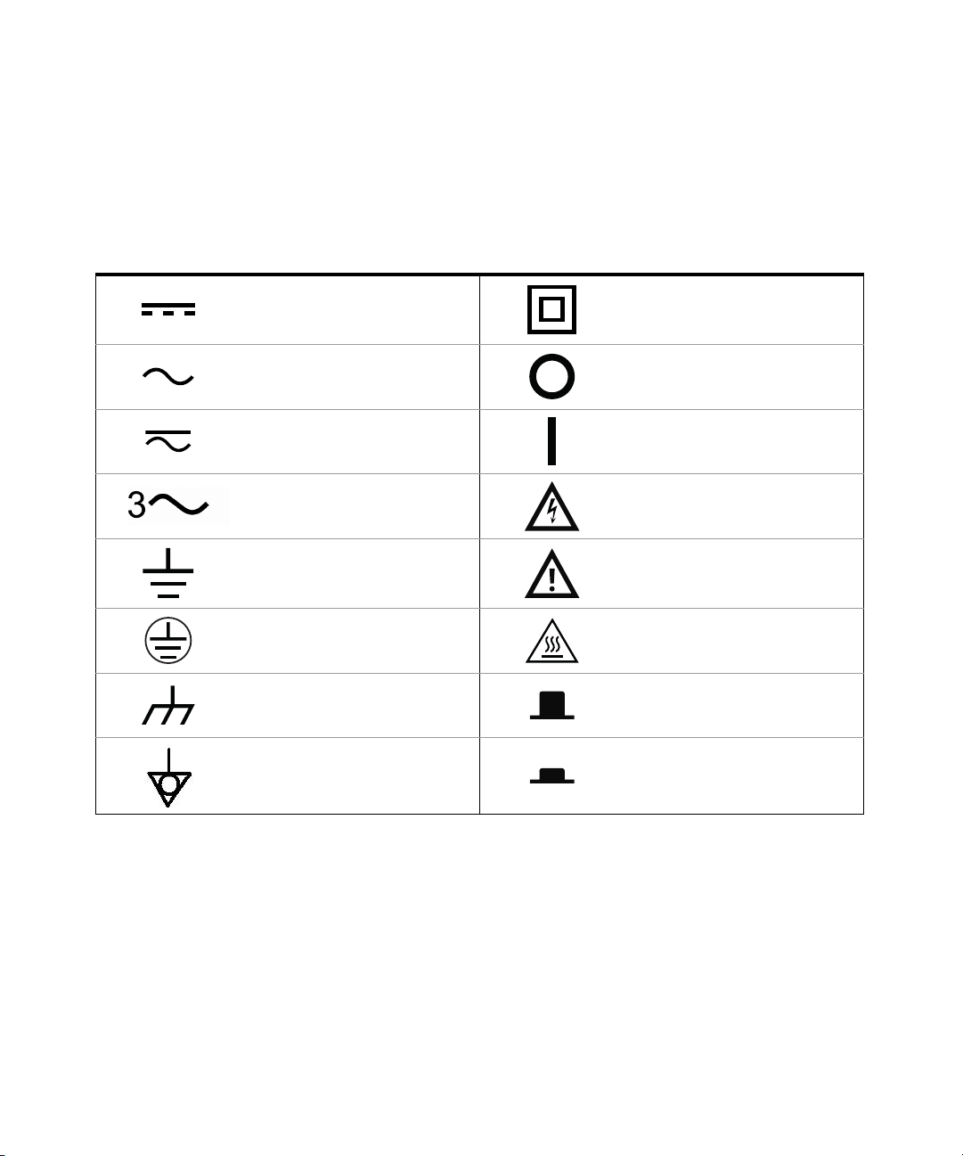
The following symbols on the instrument and in the documentation indicate
precautions which must be taken to maintain safe operation of the instrument.
Direct current (DC)
Alternating current (AC) Off (mains supply)
Both direct and alternating current On (mains supply)
Three-phase alternating current Caution, risk of electric shock
Earth (ground) terminal
Protective earth (ground) terminal Caution, hot surface
Equipment protected throughout by
double insulation or reinforced
insulation
Caution, risk of danger (refer to this
manual for specific Warning or Caution
information)
Frame or chassis (ground) terminal Out position of a bi-stable push control
Equipotentiality In position of a bi-stable push control
Keysight U2761A User’s Guide 5
Page 6

General Safety Information
WARNING
CAUTION
The following general safety precautions must be observed during all phases of
operation of this instrument. Failure to comply with these precautions or with
specific warnings elsewhere in this manual violates safety standards of design,
manufacture and intended use of the instrument. Keysight Technologies assumes
no liability for the customer’s failure to comply with these requirements.
– Do not operate the product in an explosive atmosphere or in the presence
of flammable gases or fumes.
– Do not use the equipment if it does not operate properly. Have the
equipment inspected by qualified service personnel(s).
– Observe all markings on the instrument before connecting any wiring to
the instrument.
– Use the device with the cables provided.
– Repair or service that is not covered in this manual should only be
performed by qualified personnel(s).
6 Keysight U2761A User’s Guide
Page 7

Environmental Conditions
CAUTION
This instrument is designed for indoor use and in the area with low condensation.
The table below shows the general environmental requirements for this
instrument.
Environmental condition Requirement
Operating temperature 0 °C to 50 °C
Operating humidity 20 to 85% RH non-condensing
Storage temperature –20 °C to 70 °C
Storage humidity 5 to 90% RH non-condensing
The U2761A USB modular function/arbitrary waveform generator complies
with the following safety and EMC requirements.
– IEC 61010-1:2001/EN61010-1:2001 (2nd Edition)
– Canada: CAN/CSA-C22.2 No. 61010-1-04
– USA: ANSI/UL 61010-1:2004
– IEC 61326-2002/EN 61326:1997+A1:1998+A2:2001+A3:2003
– Canada: ICES-001:2004
– Australia/New Zealand: AS/NZS CISPR11:2004
Keysight U2761A User’s Guide 7
Page 8
Regulatory Markings
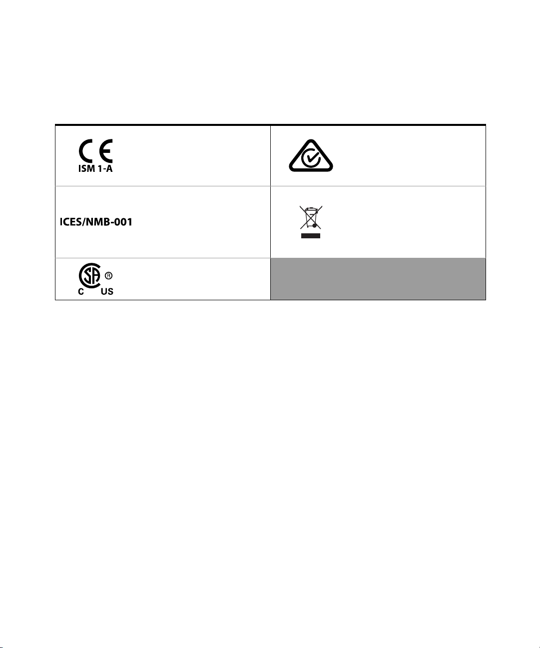
The CE mark is a registered trademark
of the European Community. This CE
mark shows that the product complies
with all the relevant European Legal
Directives.
ICES/NMB-001 indicates that this ISM
device complies with the
Canadian ICES-001.
Cet appareil ISM est conforme a la
norme NMB-001 du Canada.
The CSA mark is a registered
trademark of the Canadian
Standards Association.
The RCM mark is a registered
trademark of the Australian
Communications and Media Authority.
This instrument complies with the
WEEE Directive (2002/96/EC) marking
requirement. This affixed product label
indicates that you must not discard
this electrical or electronic product in
domestic household waste.
8 Keysight U2761A User’s Guide
Page 9

Waste Electrical and Electronic Equipment (WEEE) Directive 2002/ 96/EC
This instrument complies with the WEEE Directive (2002/96/EC) marking
requirement. This affixed product label indicates that you must not discard this
electrical or electronic product in domestic household waste.
Product category:
With reference to the equipment types in the WEEE directive Annex 1, this
instrument is classified as a “Monitoring and Control Instrument” product.
The affixed product label is as shown below.
Do not dispose in domestic household waste.
To return this unwanted instrument, contact your nearest Keysight Service Center,
or visit http://about.keysight.com/en/companyinfo/environment/takeback.shtml
for more information.
Sales and Technical Support
To contact Keysight for sales and technical support, refer to the support links on
the following Keysight websites:
– www.keysight.com/find/U2761A
(product-specific information and support, software and
documentation updates)
– www.keysight.com/find/assist
(worldwide contact information for repair and service)
Keysight U2761A User’s Guide 9
Page 10

THIS PAGE HAS BEEN INTENTIONALLY LEFT BLANK.
10 Keysight U2761A User’s Guide
Page 11

Table of Contents
Safety Symbols . . . . . . . . . . . . . . . . . . . . . . . . . . . . . . . . . . . . . . . . . . . . .5
General Safety Information . . . . . . . . . . . . . . . . . . . . . . . . . . . . . . . . . . . .6
Environmental Conditions . . . . . . . . . . . . . . . . . . . . . . . . . . . . . . . . . . . .7
Regulatory Markings . . . . . . . . . . . . . . . . . . . . . . . . . . . . . . . . . . . . . . . . .8
Waste Electrical and Electronic Equipment (WEEE) Directive
2002/96/EC . . . . . . . . . . . . . . . . . . . . . . . . . . . . . . . . . . . . . . . . . . . . .9
Product category: . . . . . . . . . . . . . . . . . . . . . . . . . . . . . . . . . . . . . . . .9
Sales and Technical Support . . . . . . . . . . . . . . . . . . . . . . . . . . . . . . . . . .9
1 Getting Started
Introduction . . . . . . . . . . . . . . . . . . . . . . . . . . . . . . . . . . . . . . . . . . . . . .20
Product at a Glance . . . . . . . . . . . . . . . . . . . . . . . . . . . . . . . . . . . . . . . .21
Product Outlook . . . . . . . . . . . . . . . . . . . . . . . . . . . . . . . . . . . . . . . . .21
Product Dimensions . . . . . . . . . . . . . . . . . . . . . . . . . . . . . . . . . . . . . . . .23
Dimensions Without Bumpers . . . . . . . . . . . . . . . . . . . . . . . . . . . . . .23
Dimensions With Bumpers . . . . . . . . . . . . . . . . . . . . . . . . . . . . . . . .24
Standard Purchase Items . . . . . . . . . . . . . . . . . . . . . . . . . . . . . . . . . . . .25
Inspection and Maintenance . . . . . . . . . . . . . . . . . . . . . . . . . . . . . . . . .26
Initial Inspection . . . . . . . . . . . . . . . . . . . . . . . . . . . . . . . . . . . . . . . . .26
Electrical Check . . . . . . . . . . . . . . . . . . . . . . . . . . . . . . . . . . . . . . . . .26
General Maintenance . . . . . . . . . . . . . . . . . . . . . . . . . . . . . . . . . . . . .26
Installation and Configuration . . . . . . . . . . . . . . . . . . . . . . . . . . . . . . . .27
55-Pin Backplane Connector Pin Configuration . . . . . . . . . . . . . . . .28
Chassis Installation . . . . . . . . . . . . . . . . . . . . . . . . . . . . . . . . . . . . . .29
Activate Your Device License . . . . . . . . . . . . . . . . . . . . . . . . . . . . . . . . .30
To Activate Your Device License . . . . . . . . . . . . . . . . . . . . . . . . . . . .30
To Verify your Device License . . . . . . . . . . . . . . . . . . . . . . . . . . . . . .32
2 Features and Functions
Output Configuration . . . . . . . . . . . . . . . . . . . . . . . . . . . . . . . . . . . . . . .34
Keysight U2761A User’s Guide 11
Page 12

Introduction . . . . . . . . . . . . . . . . . . . . . . . . . . . . . . . . . . . . . . . . . . . . 34
Output Function . . . . . . . . . . . . . . . . . . . . . . . . . . . . . . . . . . . . . . . . 34
Output Frequency . . . . . . . . . . . . . . . . . . . . . . . . . . . . . . . . . . . . . . . 37
Output Amplitude . . . . . . . . . . . . . . . . . . . . . . . . . . . . . . . . . . . . . . . 39
DC Offset Voltage . . . . . . . . . . . . . . . . . . . . . . . . . . . . . . . . . . . . . . . 41
Output Units . . . . . . . . . . . . . . . . . . . . . . . . . . . . . . . . . . . . . . . . . . . 42
Output Termination . . . . . . . . . . . . . . . . . . . . . . . . . . . . . . . . . . . . . . 43
Duty Cycle (Square Waves) . . . . . . . . . . . . . . . . . . . . . . . . . . . . . . . . 45
Symmetry (Ramp Wave) . . . . . . . . . . . . . . . . . . . . . . . . . . . . . . . . . . 47
Output Control . . . . . . . . . . . . . . . . . . . . . . . . . . . . . . . . . . . . . . . . . 48
Set Output Using SCPI Commands . . . . . . . . . . . . . . . . . . . . . . . . . 49
Pulse Waveform . . . . . . . . . . . . . . . . . . . . . . . . . . . . . . . . . . . . . . . . . . . 51
Pulse Period . . . . . . . . . . . . . . . . . . . . . . . . . . . . . . . . . . . . . . . . . . . . 51
Pulse Width . . . . . . . . . . . . . . . . . . . . . . . . . . . . . . . . . . . . . . . . . . . . 52
Pulse Duty Cycle . . . . . . . . . . . . . . . . . . . . . . . . . . . . . . . . . . . . . . . . 53
Generate Pulse Waveform Using SCPI Commands . . . . . . . . . . . . . 54
Amplitude Modulation (AM) . . . . . . . . . . . . . . . . . . . . . . . . . . . . . . . . . . 55
To Select AM . . . . . . . . . . . . . . . . . . . . . . . . . . . . . . . . . . . . . . . . . . . 55
Carrier Waveform . . . . . . . . . . . . . . . . . . . . . . . . . . . . . . . . . . . . . . . 56
Carrier Frequency . . . . . . . . . . . . . . . . . . . . . . . . . . . . . . . . . . . . . . . 57
Modulating Waveform . . . . . . . . . . . . . . . . . . . . . . . . . . . . . . . . . . . . 58
Modulating Waveform Frequency . . . . . . . . . . . . . . . . . . . . . . . . . . . 59
Modulation Depth . . . . . . . . . . . . . . . . . . . . . . . . . . . . . . . . . . . . . . . 59
Generate AM Using SCPI Commands . . . . . . . . . . . . . . . . . . . . . . . . 60
Frequency Modulation (FM) . . . . . . . . . . . . . . . . . . . . . . . . . . . . . . . . . . 61
To Select FM . . . . . . . . . . . . . . . . . . . . . . . . . . . . . . . . . . . . . . . . . . . 61
Carrier Waveform . . . . . . . . . . . . . . . . . . . . . . . . . . . . . . . . . . . . . . . 62
Carrier Frequency . . . . . . . . . . . . . . . . . . . . . . . . . . . . . . . . . . . . . . . 63
Modulating Waveform . . . . . . . . . . . . . . . . . . . . . . . . . . . . . . . . . . . . 64
Modulating Waveform Frequency . . . . . . . . . . . . . . . . . . . . . . . . . . . 64
Frequency Deviation . . . . . . . . . . . . . . . . . . . . . . . . . . . . . . . . . . . . . 65
Generate FM Using SCPI Commands . . . . . . . . . . . . . . . . . . . . . . . . 66
Phase Modulation (PM) . . . . . . . . . . . . . . . . . . . . . . . . . . . . . . . . . . . . . 67
To Select PM . . . . . . . . . . . . . . . . . . . . . . . . . . . . . . . . . . . . . . . . . . . 67
Carrier Waveform . . . . . . . . . . . . . . . . . . . . . . . . . . . . . . . . . . . . . . . 68
12 Keysight U2761A User’s Guide
Page 13

Carrier Frequency . . . . . . . . . . . . . . . . . . . . . . . . . . . . . . . . . . . . . . . 69
Modulating Waveform . . . . . . . . . . . . . . . . . . . . . . . . . . . . . . . . . . . .70
Modulating Waveform Frequency . . . . . . . . . . . . . . . . . . . . . . . . . . .70
Phase Deviation . . . . . . . . . . . . . . . . . . . . . . . . . . . . . . . . . . . . . . . . .71
Generate PM Using SCPI Commands . . . . . . . . . . . . . . . . . . . . . . . .71
Frequency-Shift Keying (FSK) Modulation . . . . . . . . . . . . . . . . . . . . . . .72
To Select FSK Modulation . . . . . . . . . . . . . . . . . . . . . . . . . . . . . . . . .72
Carrier Waveform . . . . . . . . . . . . . . . . . . . . . . . . . . . . . . . . . . . . . . . . 73
FSK Carrier Frequency . . . . . . . . . . . . . . . . . . . . . . . . . . . . . . . . . . . .74
FSK “Hop” Frequency . . . . . . . . . . . . . . . . . . . . . . . . . . . . . . . . . . . .75
FSK Rate . . . . . . . . . . . . . . . . . . . . . . . . . . . . . . . . . . . . . . . . . . . . . .76
Generate FSK Modulation Using SCPI Commands . . . . . . . . . . . . .76
Phase-Shift Keying (PSK) Modulation . . . . . . . . . . . . . . . . . . . . . . . . . .77
To Select PSK Modulation . . . . . . . . . . . . . . . . . . . . . . . . . . . . . . . . .77
Carrier Waveform . . . . . . . . . . . . . . . . . . . . . . . . . . . . . . . . . . . . . . . . 78
PSK Carrier Frequency . . . . . . . . . . . . . . . . . . . . . . . . . . . . . . . . . . .79
PSK Rate . . . . . . . . . . . . . . . . . . . . . . . . . . . . . . . . . . . . . . . . . . . . . .80
PSK Deviation . . . . . . . . . . . . . . . . . . . . . . . . . . . . . . . . . . . . . . . . . .80
Generate PSK Modulation Using SCPI Commands . . . . . . . . . . . . .81
Amplitude-Shift Keying (ASK) Modulation . . . . . . . . . . . . . . . . . . . . . . .82
To Select ASK Modulation . . . . . . . . . . . . . . . . . . . . . . . . . . . . . . . . .82
Carrier Waveform . . . . . . . . . . . . . . . . . . . . . . . . . . . . . . . . . . . . . . . . 83
Carrier Frequency . . . . . . . . . . . . . . . . . . . . . . . . . . . . . . . . . . . . . . . 84
ASK Rate . . . . . . . . . . . . . . . . . . . . . . . . . . . . . . . . . . . . . . . . . . . . . .85
Generate ASK Modulation Using SCPI Commands . . . . . . . . . . . . .85
Frequency Sweep . . . . . . . . . . . . . . . . . . . . . . . . . . . . . . . . . . . . . . . . . .86
To Select Sweep . . . . . . . . . . . . . . . . . . . . . . . . . . . . . . . . . . . . . . . .86
Start Frequency and Stop Frequency . . . . . . . . . . . . . . . . . . . . . . . .87
Sweep Mode . . . . . . . . . . . . . . . . . . . . . . . . . . . . . . . . . . . . . . . . . . .88
Sweep Time . . . . . . . . . . . . . . . . . . . . . . . . . . . . . . . . . . . . . . . . . . . .88
Sweep Trigger Source . . . . . . . . . . . . . . . . . . . . . . . . . . . . . . . . . . . .89
Set Frequency Sweep Using SCPI Commands . . . . . . . . . . . . . . . . .90
Triggering . . . . . . . . . . . . . . . . . . . . . . . . . . . . . . . . . . . . . . . . . . . . . . . .91
Trigger Source Choices . . . . . . . . . . . . . . . . . . . . . . . . . . . . . . . . . . .91
Keysight U2761A User’s Guide 13
Page 14

Internal Triggering . . . . . . . . . . . . . . . . . . . . . . . . . . . . . . . . . . . . . . . 92
Manual Triggering . . . . . . . . . . . . . . . . . . . . . . . . . . . . . . . . . . . . . . . 92
External Triggering . . . . . . . . . . . . . . . . . . . . . . . . . . . . . . . . . . . . . . 93
Trigger Input Signal . . . . . . . . . . . . . . . . . . . . . . . . . . . . . . . . . . . . . . 94
Trigger Output Signal . . . . . . . . . . . . . . . . . . . . . . . . . . . . . . . . . . . . 94
Set Triggering Using SCPI Commands . . . . . . . . . . . . . . . . . . . . . . . 96
Arbitrary Waveforms . . . . . . . . . . . . . . . . . . . . . . . . . . . . . . . . . . . . . . . 97
To Create and Store an Arbitrary Waveform . . . . . . . . . . . . . . . . . . 97
3Characteristics and Specifications
Index
14 Keysight U2761A User’s Guide
Page 15

List of Figures
Figure 1-1 55-pin backplane connector pin configuration . . . . . .28
Figure 2-1 U2761A soft front panel . . . . . . . . . . . . . . . . . . . . . . . .36
Figure 2-2 Top panel view of the U2761A . . . . . . . . . . . . . . . . . . .37
Figure 2-3 Panel view of the frequency section . . . . . . . . . . . . . .38
Figure 2-4 Panel view of the amplitude section . . . . . . . . . . . . . .40
Figure 2-5 Panel view of the DC offset section . . . . . . . . . . . . . . .41
Figure 2-6 Panel view of the Tools menu . . . . . . . . . . . . . . . . . . .44
Figure 2-7 Square wave duty cycles . . . . . . . . . . . . . . . . . . . . . . .45
Figure 2-8 Panel view of the duty cycle section . . . . . . . . . . . . . .46
Figure 2-9 Ramp wave duty cycles . . . . . . . . . . . . . . . . . . . . . . . .47
Figure 2-10 Panel view of the symmetry section . . . . . . . . . . . . . .47
Figure 2-11 Panel view of the output section . . . . . . . . . . . . . . . . .48
Figure 2-12 Pulse waveform . . . . . . . . . . . . . . . . . . . . . . . . . . . . . .51
Figure 2-13 Panel view of the pulse width section . . . . . . . . . . . . .52
Figure 2-14 AM waveform . . . . . . . . . . . . . . . . . . . . . . . . . . . . . . . .55
Figure 2-15 Panel view of AM . . . . . . . . . . . . . . . . . . . . . . . . . . . . .56
Figure 2-16 Panel view of the Arbitrary waveform . . . . . . . . . . . . .57
Figure 2-17 FM waveform . . . . . . . . . . . . . . . . . . . . . . . . . . . . . . . .61
Figure 2-18 Panel view of FM . . . . . . . . . . . . . . . . . . . . . . . . . . . . .62
Figure 2-19 PM waveform . . . . . . . . . . . . . . . . . . . . . . . . . . . . . . . .67
Figure 2-20 Panel view of PM . . . . . . . . . . . . . . . . . . . . . . . . . . . . .68
Figure 2-21 FSK modulation waveform . . . . . . . . . . . . . . . . . . . . . .72
Figure 2-22 Panel view of FSK . . . . . . . . . . . . . . . . . . . . . . . . . . . . .73
Figure 2-23 PSK modulation waveform . . . . . . . . . . . . . . . . . . . . . .77
Figure 2-24 Panel view of PSK . . . . . . . . . . . . . . . . . . . . . . . . . . . . .78
Figure 2-25 ASK modulation waveform . . . . . . . . . . . . . . . . . . . . . .82
Figure 2-26 Panel view of ASK . . . . . . . . . . . . . . . . . . . . . . . . . . . . .83
Figure 2-27 Frequency sweep . . . . . . . . . . . . . . . . . . . . . . . . . . . . .86
Figure 2-28 Panel view of sweep . . . . . . . . . . . . . . . . . . . . . . . . . . .87
Figure 2-29 Trigger input pulse . . . . . . . . . . . . . . . . . . . . . . . . . . . .94
Figure 2-30 Trigger output pulse . . . . . . . . . . . . . . . . . . . . . . . . . . .94
Figure 2-31 Ramp waveform . . . . . . . . . . . . . . . . . . . . . . . . . . . . . .97
Figure 2-32 Waveform download in progress . . . . . . . . . . . . . . . . .99
Keysight U2761A User’s Guide 15
Page 16

THIS PAGE HAS BEEN INTENTIONALLY LEFT BLANK.
16 Keysight U2761A User’s Guide
Page 17

List of Tables
Table 1-1 Synchronous Simultaneous Interface (SSI) connector
pin description . . . . . . . . . . . . . . . . . . . . . . . . . . . . .28
Table 2-1 Output functions . . . . . . . . . . . . . . . . . . . . . . . . . . . . . .34
Table 2-2 Output frequency range . . . . . . . . . . . . . . . . . . . . . . . .37
Table 2-3 Carrier frequency for AM . . . . . . . . . . . . . . . . . . . . . . .57
Table 2-4 Carrier frequency for FM . . . . . . . . . . . . . . . . . . . . . . .63
Table 2-5 Carrier frequency for PM . . . . . . . . . . . . . . . . . . . . . . .69
Table 2-6 Carrier frequency for FSK . . . . . . . . . . . . . . . . . . . . . . .74
Table 2-7 “Hop” frequency . . . . . . . . . . . . . . . . . . . . . . . . . . . . . .75
Table 2-8 Carrier frequency for PSK . . . . . . . . . . . . . . . . . . . . . .79
Table 2-9 Carrier frequency for ASK . . . . . . . . . . . . . . . . . . . . . .84
Keysight U2761A User’s Guide 17
Page 18

THIS PAGE HAS BEEN INTENTIONALLY LEFT BLANK.
18 Keysight U2761A User’s Guide
Page 19

Keysight U2761A USB Modular Function/
Arbitrary Waveform Generator
User’s Guide
1 Getting Started
Introduction 20
Product at a Glance 21
Product Dimensions 23
Standard Purchase Items 25
Inspection and Maintenance 26
Installation and Configuration 27
Activate Your Device License 30
This chapter provides the introduction of the Keysight U2761A that helps you get
acquainted with the product and the product outlook. This chapter also includes
the installation and configuration procedures that will help you get started with
the Keysight U2761A.
19
Page 20

1 Getting Started
Introduction
The Keysight U2761A is a 20 MHz USB modular function generator with Arbitrary
waveform and pulse generation capabilities. It can operate as a standalone unit or
as part of a modular unit when used with the U2781A USB modular instrument
chassis.
The Keysight U2761A adopts the latest direct digital synthesis (DDS) technology
that digitally creates Arbitrary waveforms and frequencies from a single, fixed
source frequency. DDS offers the precision of a digital control logic; reducing the
complexity of the generator while increasing the stability. Thus, creating a stable,
accurate output signal for clean, low distortion sine waves with fast rise and fall
time up to 20 MHz and linear Ramp waves up to 200 kHz.
Various features of the U2761A
– 20 MHz Sine and Square waveforms
– Hi-Speed 2.0, USBTMC 488.2 standards
– Sine, Square, Ramp, Triangle, Pulse, and DC waveforms
– 14-bit, 50 MSa/s, 64 K-point Arbitrary waveforms
– AM, FM, PM, ASK, FSK, and PSK modulation types
– 40 mVpp to 5 Vpp amplitude range for 50 Ω load, and 80 mVpp to 10 Vpp
amplitude range for open circuit
– Pulse generation
– 2 MHz maximum frequency for Arbitrary waveforms, with option U2010A
20 Keysight U2761A User’s Guide
Page 21
Product at a Glance
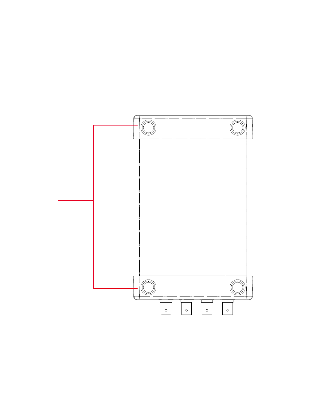
Bumpers
Product Outlook
Top View
Getting Started 1
Keysight U2761A User’s Guide 21
Page 22
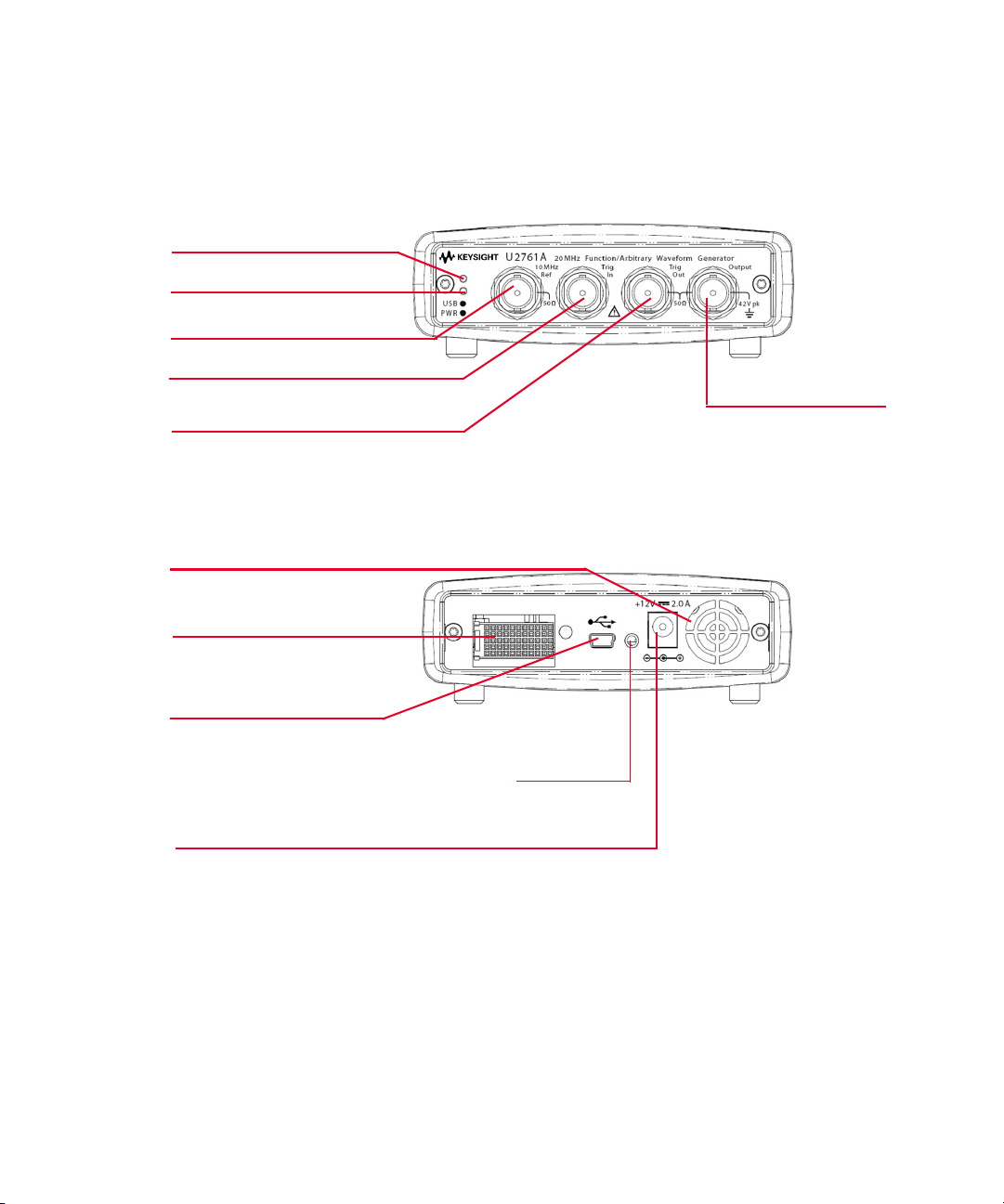
1 Getting Started
USB indicator
Power indicator
10 MHz reference connector
Trigger in connector
Trigger out connector
Output connector
Fan Ventilation
Power inlet
USB inlet
Fastening hole for USB cable with locking
mechanism
55-pin backplane connector
Front View
Rear View
22 Keysight U2761A User’s Guide
Page 23
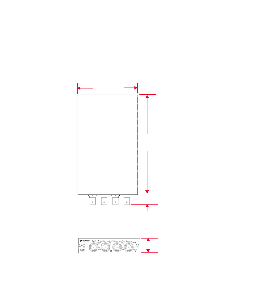
Product Dimensions
Top View
105.00 mm
175.00 mm
18.00 mm
Front View
25.00 mm
Dimensions Without Bumpers
Getting Started 1
Keysight U2761A User’s Guide 23
Page 24
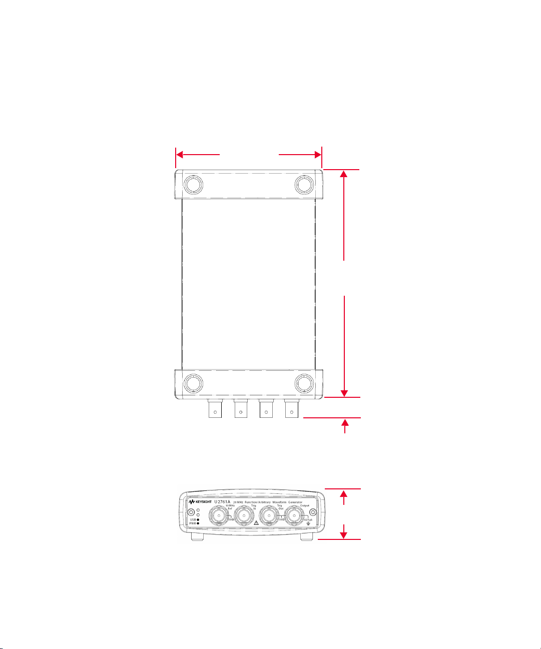
1 Getting Started
Top View
117.00 mm
180.00 mm
15.00 mm
Front View
41.00 mm
Dimensions With Bumpers
24 Keysight U2761A User’s Guide
Page 25

Standard Purchase Items
Verify the following items for the standard purchase of the U2761A. If there are
any missing or mechanically damaged items, contact the nearest Keysight Sales
Office.
4 12 V, 2 A AC/DC power adapter
4 Power cord
4 USB Standard-A to Mini-B interface cable
4 L-Mount kit (used with modular instrument chassis)
4 Keysight Automation-Ready CD-ROM (contains the IO Libraries Suite)
4 Keysight USB Modular Products and Systems Quick Start Guide
4 Keysight USB Modular Products and Systems Product Reference DVD-ROM
4 Keysight Measurement Manager Quick Reference Card
4 Certificate of Calibration
Getting Started 1
Keysight U2761A User’s Guide 25
Page 26

1 Getting Started
NOTE
Inspection and Maintenance
Initial Inspection
When you receive your Keysight U2761A, inspect the unit for any obvious damage
such as broken terminals or cracks, dents, and scratches on the casing that may
occur during shipment. If any damage is found, notify the nearest Keysight Sales
Office immediately. The front of this manual contains the warranty information.
Keep the original packaging in case the Keysight U2761A has to be returned to
Keysight in the future. If you return the Keysight U2761A for service, attach a tag
identifying the owner and model number. Also include a brief description of the
problem.
Electrical Check
The Keysight U2761A USB Modular Function/Arbitrary Waveform Generator
Service Guide will provide the complete verification and calibration procedures.
The procedures will verify to a high level of confidence that the Keysight U2761A
is operating in accordance with its specifications.
General Maintenance
Any repair that is not covered in your modular product manuals should only be
performed by qualified personnel.
1 Power off your module and remove the power cord and I/O cable from your
device.
2 Remove your module from the bumper casing.
3 Shake off any dirt that may have accumulated on the module.
4 Wipe your module with a dry cloth and install the bumper back in place.
26 Keysight U2761A User’s Guide
Page 27

Installation and Configuration
NOTE
Follow the step-by-step instructions shown in the Keysight USB Modular
Products and Systems Quick Start Guide to get started with the preparations and
installations of your Keysight U2761A.
You need to install the IVI-COM driver if you are going to use the Keysight
U2761A with Keysight VEE Pro, LabVIEW, or Microsoft
Getting Started 1
®
Visual Studio®.
Keysight U2761A User’s Guide 27
Page 28
1 Getting Started
GND
NC
GND
TRIG4
nBPUB
NC
11
GND
NC
TRIG3
GND
CLK10M
NC
10
GND
NC
GND
TRIG5
GND
NC
9
GND
NC
STAR_TRIG
NC
8
TRIG2
GND
GND
NC
GND
TRIG6
GA2
NC
7
GND
NC
TRIG1
GND
GA1
NC
6
GND
NC
GND
TRIG7
GA0
NC
5
GND
NC
TRIG0
GND
NC
NC
4
GND
VBUS
GND
+12 V
+12 V
+12 V
3
GND
GND
GND
+12 V
+12 V
+12 V
2
GND
USB_D–
USB_D+
GND
+12 V
+12 V
1
F
E
D
C
B
A
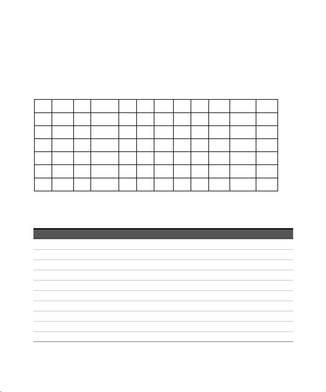
55-Pin Backplane Connector Pin Configuration
The 55-pin backplane connector is used when the Keysight U2761A module is
inserted into the U2781A USB modular instrument chassis. For more details, refer
to the Keysight U2781A USB Modular Instrument Chassis User's Guide.
Figure 1-1 55-pin backplane connector pin configuration
Tab le 1-1 Synchronous Simultaneous Interface (SSI) connector pin description
SSI timing signal Functionality
GND Ground
NC Not connected
VBUS USB bus power sensing input
USB_D+, USB_D– USB differential pair
TRIG0~TRIG7 Trigger bus
+12 V +12 V power with 4 A current
nBPUB USB backplane input detect
CLK10M 10 MHz clock source
STAR_TRIG Star trigger
GA0,GA1,GA2 Geographical address pin
28 Keysight U2761A User’s Guide
Page 29

Chassis Installation
The L-mount kit is to be installed to your Keysight U2761A module. The following
instructions describe the simple procedure of installing the L-mount kit and your
module in the U2781A chassis.
1 Unpack the L-mount kit from its packaging.
2 Remove your Keysight U2761A module from the bumper casing.
3 Using a Phillips screwdriver, fasten the L-Mount kit to your Keysight U2761A
module.
4 Insert your Keysight U2761A module into the U2781A chassis with the 55-pin
backplane connector positioned at the bottom of the module.
5 Once you have slotted the module into the chassis, tighten the screws of the
L-mount kit to secure the connection.
Getting Started 1
Keysight U2761A User’s Guide 29
Page 30
1 Getting Started
Activate Your Device License
If you have purchased a Keysight U2761A with option U2010A, you are required to
activate the device license before you can use its additional feature in the
Keysight Measurement Manager. You may activate the device license through the
Software Licensing application.
The following instructions will guide you through on how to use the Software
Licensing application.
To Activate Your Device License
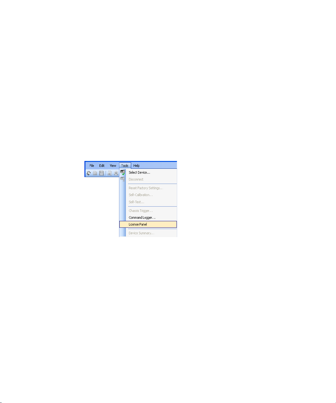
1 Go to Tools > License Panel.
30 Keysight U2761A User’s Guide
Page 31
Getting Started 1
NOTE
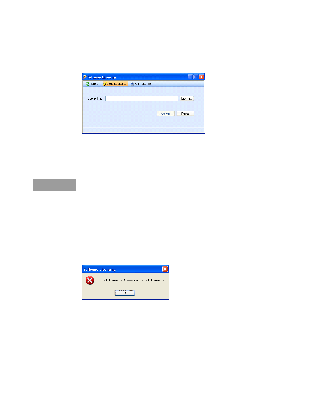
2 The Software Licensing window will appear with the Activate License tab as
the active tab.
3 Ensure that the device you want to activate is connected to your PC and is
powered on.
4 Click Browse... to locate your device license key (*.lic).
If you do not have a device license key (*.lic), you will need to redeem your
device license key at www.keysight.com/find/softwarelicense. Follow the
on-screen instructions to redeem a valid license key for your device.
5 Select your device license key and click Open.
6 Click Activate to verify your device license. If successful, the “License
Activation completed” message will be displayed in the status bar.
7 If an invalid license key is used, a warning message will appear as shown
below when you click Activate.
8 Click OK and ensure that a valid license key is selected before you click
Activate.
Keysight U2761A User’s Guide 31
Page 32
1 Getting Started
To Verify your Device License
1 Go to Tools > License Panel.
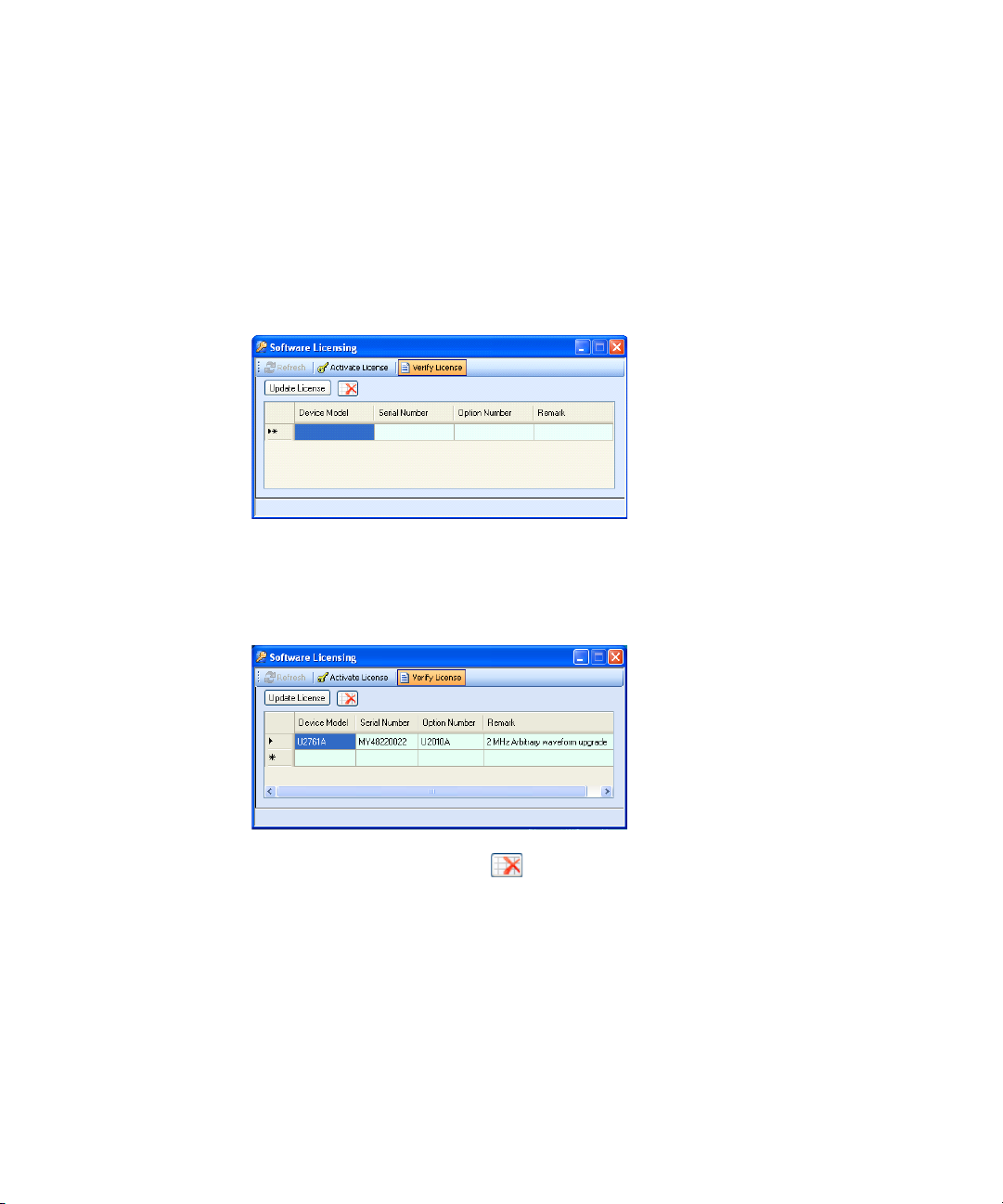
2 The Software Licensing window will appear with the Activate License tab as
3 Select the Verify License tab as the active tab.
4 Ensure that the device(s) you want to verify is connected to your PC.
5 Click Update License. The device model, serial number, and option number
the active tab.
will be displayed with a valid license.
6 Click the Clear Table icon ( ) to clear the Verify License table.
32 Keysight U2761A User’s Guide
Page 33

Keysight U2761A USB Modular Function/
Arbitrary Waveform Generator
User’s Guide
2 Features and Functions
Output Configuration 34
Pulse Waveform 51
Amplitude Modulation (AM) 55
Frequency Modulation (FM) 61
Phase Modulation (PM) 67
Frequency-Shift Keying (FSK) Modulation 72
Phase-Shift Keying (PSK) Modulation 77
Amplitude-Shift Keying (ASK) Modulation 82
Frequency Sweep 86
Triggering 91
Arbitrary Waveforms 97
In this chapter, you will learn about the functions and features offered by the
Keysight U2761A.
33
Page 34

2 Features and Functions
Output Configuration
Introduction
This section contains the information to help you configure the U2761A for
outputting waveforms. You may not need to change some of the parameters
discussed here, but they are provided so that you will have accessibility when
needed.
Output Function
The U2761A can output five standard waveforms (Sine, Square, Ramp, Triangle,
and Pulse), and DC. You can select one of the three built-in Arbitrary waveforms
or create your own custom waveforms. In addition, you can internally modulate
Sine, Square, Ramp, Triangle, and Arbitrary waveforms using AM, FM, PM, FSK,
PSK, or ASK. The linear or logarithmic frequency sweeping is available for Sine,
Square, Ramp, Triangle, and Arbitrary waveforms.
The table below shows which output functions are allowed with modulation and
sweep. Each “V” indicates a valid combination. If you change to a function that is
not applicable for modulation, or sweep; then the modulation or mode will be
disabled.
Tab le 2-1 Output functions
Sine Square Ramp Triangle Pulse DC Arbitrary
AM, FM, PM, FSK, PSK, ASK Carrier VVVV V
AM, FM, PM Internal Modulation VVVV V
FSK, PSK, ASK Internal Modulation V
Sweep Mode VVVV V
34 Keysight U2761A User’s Guide
Page 35

Features and Functions 2
Function Limitation
If you change to a function where the maximum frequency is less than the current
function, the frequency will be adjusted to the maximum value for the new
function.
For example, if you are currently outputting a 20 MHz sine wave and then change
to the Ramp function, the U2761A will automatically adjusts the output frequency
to 200 kHz (the upper limit for Ramp).
Amplitude Limitation
If you change to a function where the maximum amplitude is less than the current
function, the amplitude will automatically be adjusted to the maximum value for
the new function. This may occur when the output units are Vrms or dBm due to
the differences in crest factor for the various output functions.
For example, if you output a 2.5 Vrms Square wave (into 50 Ω) and then change to
the Sine wave function, the U2761A will automatically be adjusted the output
amplitude to 1.768 Vrms (the upper limit for Sine wave in Vrms).
Keysight U2761A User’s Guide 35
Page 36
2 Features and Functions
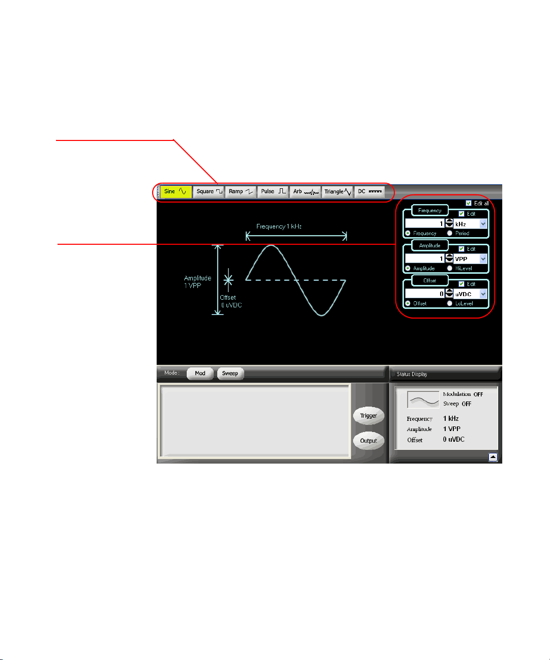
Waveform pattern selection
Waveform parameters
Soft Front Panel Operation
The following figure shows the soft front panel of the U2761A.
36 Keysight U2761A User’s Guide
Figure 2-1 U2761A soft front panel
Page 37
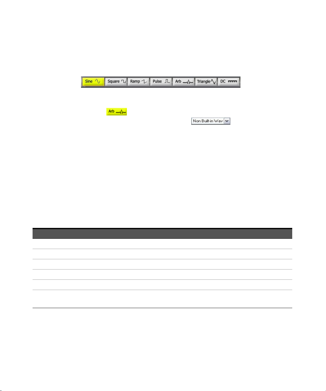
To select a function, click any of the functions on the top panel as shown below.
When a function is selected, the button will be illuminated.
Figure 2-2 Top panel view of the U2761A
Click Arb to output the Arbitrary waveform. Select other Arbitrary
waveform choices from the drop down list .
Remote Interface Operation
FUNCtion {SINusoid|SQUare|RAMP|PULSe|DC|USER}
You can also use the APPLy command to select the function, frequency,
amplitude, and offset.
Output Frequency
As shown below, the output frequency range depends on the function currently
selected. The default frequency is 1 kHz for all functions.
Features and Functions 2
Tab le 2-2 Output frequency range
Function Minimum frequency Maximum frequency
Sine 1 μHz 20 MHz
Square 1 μHz 20 MHz
Ramp, Triangle 1 μHz 200 kHz
Pulse 500 μHz 5 MHz
DC Not applicable Not applicable
Arbitrary 1 μHz 200 kHz
2 MHz (Option U2010A)
Keysight U2761A User’s Guide 37
Page 38
2 Features and Functions
Function Limitations
If you change to a function where the maximum frequency is less than the current
function, the frequency will be adjusted to the maximum value for the new
function.
For example, if you are currently outputting a 20 MHz sine wave and then change
to the Ramp function, the U2761A will automatically adjusts the output frequency
to 200 kHz (the upper limit for Ramp).
Duty Cycle Limitations
For Square waveforms, the U2761A may not be able to use the full range of duty
cycle values at higher frequencies as shown below.
– 20% to 80% (frequency
≤ 10 MHz)
– 40% to 60% (frequency
If you change to a frequency that cannot produce the current duty cycle, the duty
cycle is automatically adjusted to the maximum value for the new frequency.
For example, if you currently have the duty cycle set to 70% and then change the
frequency to 12 MHz, the U2761A will automatically adjusts the duty cycle to 60%
(the upper limit for this frequency).
> 10 MHz)
Soft Front Panel Operation
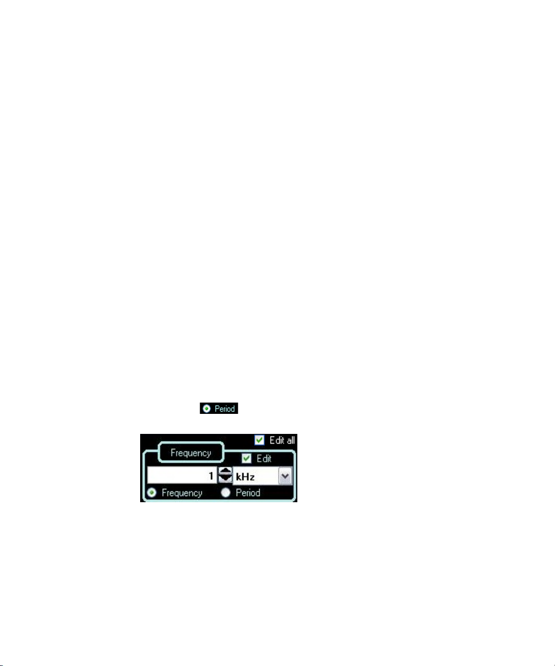
On the Frequency panel as shown in Figure 2-3, input the desired frequency value
and select the unit from the drop down list. To set the waveform period instead,
select Period .
Figure 2-3 Panel view of the frequency section
38 Keysight U2761A User’s Guide
Page 39

Remote Interface Operation
V
pp
2 V
maxVoffset
–()×≤
You can also use the APPLy command to select the function, frequency,
amplitude, and offset.
Output Amplitude
The default amplitude is 1 Vpp (into 50 Ω) for all functions.
Offset Voltage Limitations
The relation between the output amplitude and offset voltage is shown below.
Vmax is the maximum peak voltage for the selected output termination (5 V for a
50 Ω load or 10 V for a high-impedance load).
Limits Due to Output Termination
If you change the output termination setting, the value of the output amplitude
will be adjusted (and no error will be generated).
Features and Functions 2
FREQuency <frequency>
For example, if you set the amplitude to 5 Vpp and then change the output
termination from 50 Ω to “high impedance”, the amplitude value will double to
10 Vpp. If you change from “high impedance” to 50 Ω, the displayed amplitude
value will drop to half. For more information, see “Output Termination” on
page 43.
Keysight U2761A User’s Guide 39
Page 40
2 Features and Functions
Limits Due to Units Selection
In some cases, the amplitude limits are determined by the output units selected.
This may occur when the units are Vrms or dBm due to the differences in crest
factor for the various output functions.
For example, if you output a 2.5 Vrms Square wave (into 50 Ω) and then change to
the Sine wave function, the U2761A will automatically adjusts the output
amplitude to 1.768 Vrms (the upper limit for Sine wave in Vrms).
You can set the output amplitude in Vpp, Vrms, or dBm. For more information, see
“Output Units” on page 42.
You cannot specify the output amplitude in dBm if the output termination is set to
“high impedance”.
Soft Front Panel Operation
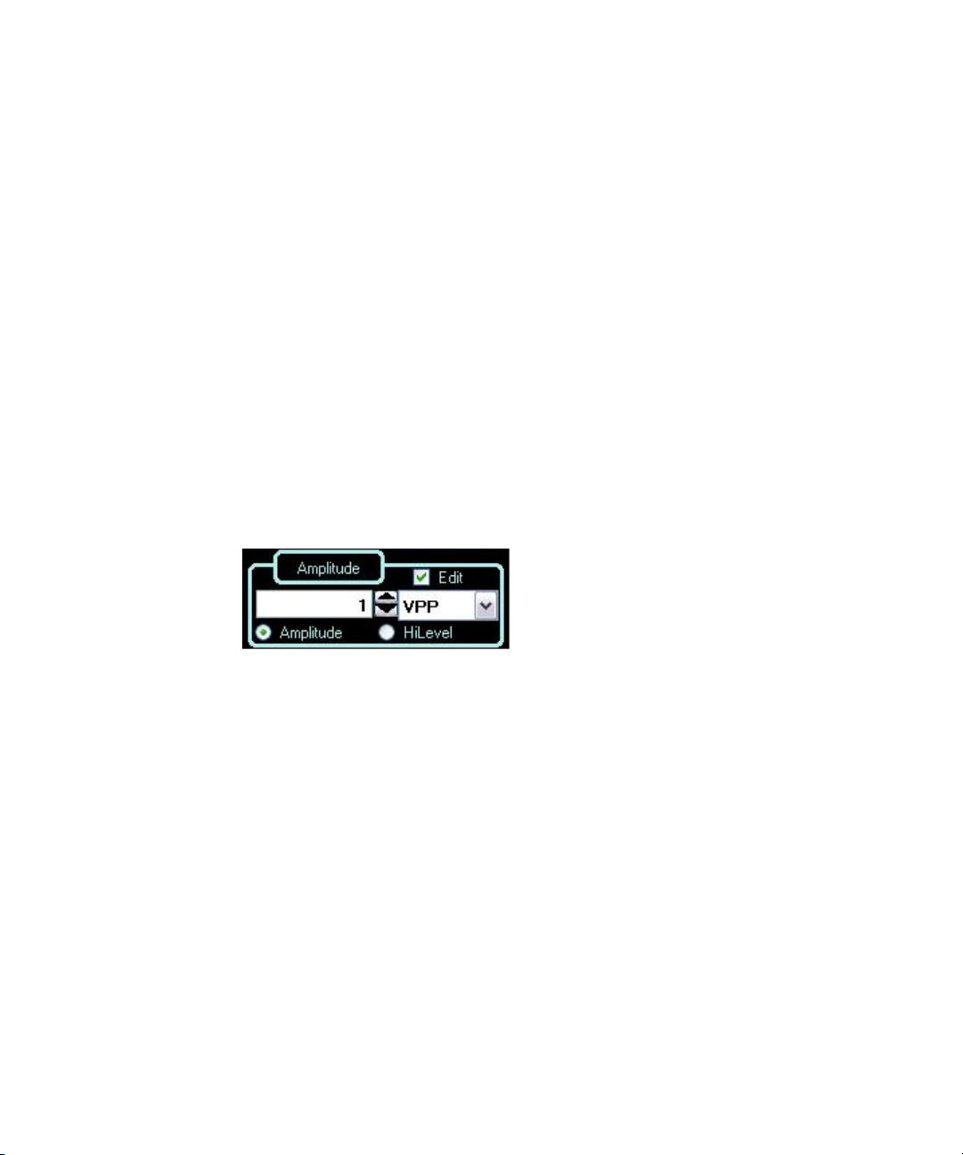
On the Amplitude panel as shown in Figure 2-4, input the desired amplitude value
and select the unit from the drop down list.
Figure 2-4 Panel view of the amplitude section
Remote Interface Operation
VOLTage <amplitude>
Or, you can set the amplitude by specifying a high level and low level using the
following commands.
VOLTage:HIGH <voltage>
VOLTage:LOW <voltage>
You can also use the APPLy command to select the function, frequency,
amplitude, and offset.
40 Keysight U2761A User’s Guide
Page 41
DC Offset Voltage
V
offsetVmax
V
pp
2
--------
–≤
The default offset is 0 V for all functions.
Limits Due to Amplitude
The relation between the offset voltage and output amplitude is shown below.
Vmax is the maximum peak voltage for the selected output termination (5 V for a
50 Ω load or 10 V for a high-impedance load).
If the specified offset voltage is not valid, the U2761A will automatically adjusts it
to the maximum DC voltage allowed with the specified amplitude.
Soft Front Panel Operation
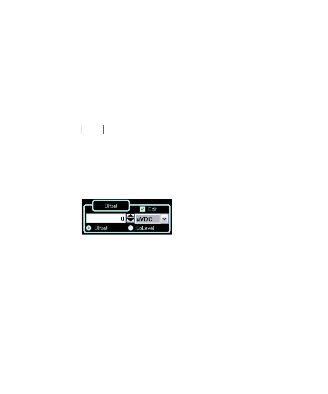
On the Offset panel as shown in Figure 2-5, input the desired offset value and
select the unit from the drop down list.
Features and Functions 2
Keysight U2761A User’s Guide 41
Figure 2-5 Panel view of the DC offset section
Remote Interface Operation
VOLTage:OFFSet <offset>
Or, you can set the offset by specifying a high level and low level using the
following commands.
VOLTage:HIGH <voltage>
VOLTage:LOW <voltage>
You can also use the APPLy command to select the function, frequency,
amplitude, and offset.
Page 42

2 Features and Functions
Output Units
This configuration applies to output amplitude only. At power-on, the units for
output amplitude are volts peak-to-peak.
– The output units consist of Vpp, Vrms, or dBm. The default unit is Vpp.
– The unit setting is stored in volatile memory. The units are set to “Vpp” upon
power-off or after a remote interface reset.
– The output units for amplitude cannot be set to dBm if the output termination
is currently set to “high impedance”. The units are automatically converted to
Vpp.
Soft Front Panel Operation
On the Amplitude panel as shown in Figure 2-4, input the desired amplitude value
and select the unit from the drop down list.
Remote Interface Operation
VOLTage:UNIT {VPP|VRMS|DBM}
42 Keysight U2761A User’s Guide
Page 43

Output Termination
This configuration applies to output amplitude and offset voltage only. The
Keysight U2761A has a fixed series output impedance of 50 Ω to the device
output connector. If the actual load impedance is different from the specified
value, the amplitude and offset levels will be incorrect.
– The range of the output termination is 1 Ω to 10 kΩ, or Infinite. The default
value is 50
– The output termination setting is stored in volatile memory and upon power-off
or after a remote interface reset, the setting will return to a default value.
– If you specify a 50 Ω termination but are actually terminating into an open
circuit, the actual output will be twice the value specified.
For example, if you set the offset to 100 mVDC (and specify a 50 Ω load) but
are terminating the output into an open circuit, the actual offset will be
200 mVDC.
– If you change the output termination setting, the output amplitude and offset
levels are automatically adjusted (no error will be generated).
For example, if you set the amplitude to 5 Vpp and then change the output
termination from 50 Ω to “high impedance”, the amplitude value will double to
10 Vpp. If you change from “high impedance” to 50 Ω, the displayed amplitude
value will drop to half.
Ω
Features and Functions 2
.
– You cannot specify the output amplitude in dBm if the output termination is
currently set to “high impedance”. The units are automatically converted to
Vpp.
Keysight U2761A User’s Guide 43
Page 44
2 Features and Functions
Soft Front Panel Operation
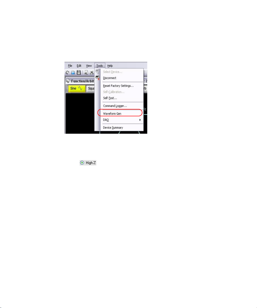
Click Tools and select Waveform Gen as shown in the following.
Figure 2-6 Panel view of the Tools menu
Then, select the Output Setup tab, input the desired load impedance value on
the Impedance Load panel and select the unit from the drop down list, or select
High Z for high impedance load.
Remote Interface Operation
OUTPut:LOAD {<ohms>|INFinity}
44 Keysight U2761A User’s Guide
Page 45
Duty Cycle (Square Waves)
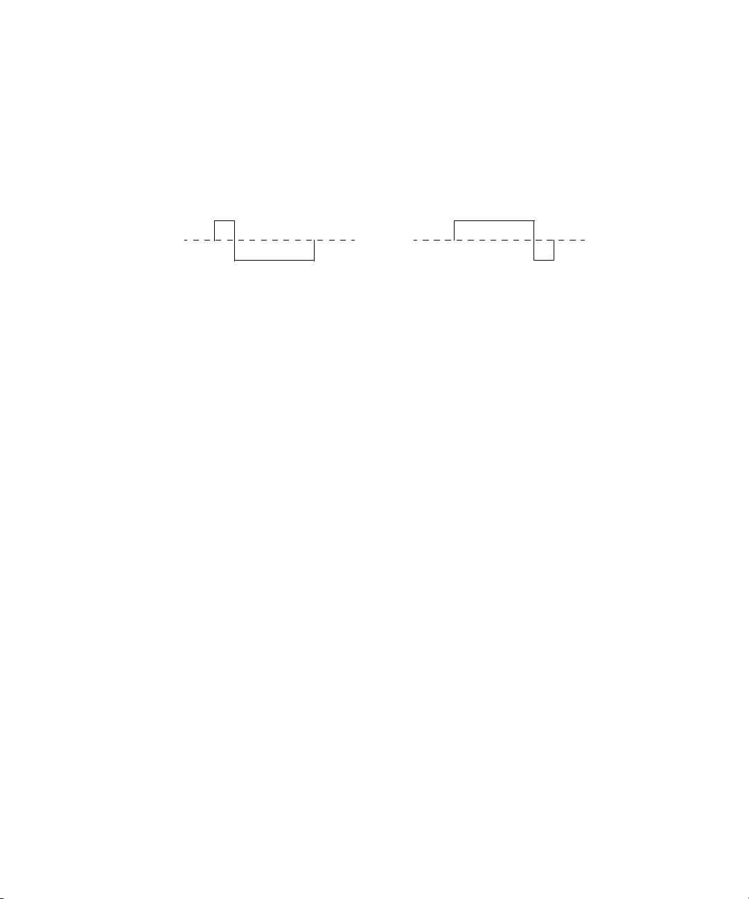
20% Duty Cycle 80% Duty Cycle
The duty cycle of a Square wave represents the amount of time per cycle that the
Square wave is at a high level (assuming that the waveform is not inverted).
Figure 2-7 Square wave duty cycles
Refer to “Pulse Waveform” on page 51 for the information on the duty cycle for
Pulse waveforms.
Duty Cycle
– 20% to 80% (frequency ≤ 10 MHz)
– 40% to 60% (frequency > 10 MHz)
The duty cycle is stored in volatile memory where the duty cycle is set to default
50% upon power-off or after a remote interface reset.
The duty cycle setting is stored when you change from Square wave to another
function. Thus, when you return to the Square function, the previous duty cycle is
used.
Features and Functions 2
Limits Due to Frequency
If the Square wave function is selected and you change to a frequency that cannot
produce the current duty cycle, the duty cycle is automatically adjusted to the
maximum value for the new frequency.
For example, if you currently have the duty cycle set to 70% and then change the
frequency to 12 MHz, the U2761A will automatically adjusts the duty cycle to 60%
(the upper limit for this frequency).
The duty cycle setting does not apply to a Square waveform used as the
modulating waveform for AM, FM, or PM. A 50% duty cycle is always used for a
modulating Square waveform. The duty cycle setting applies only to a Square
waveform carrier.
Keysight U2761A User’s Guide 45
Page 46
2 Features and Functions
Soft Front Panel Operation
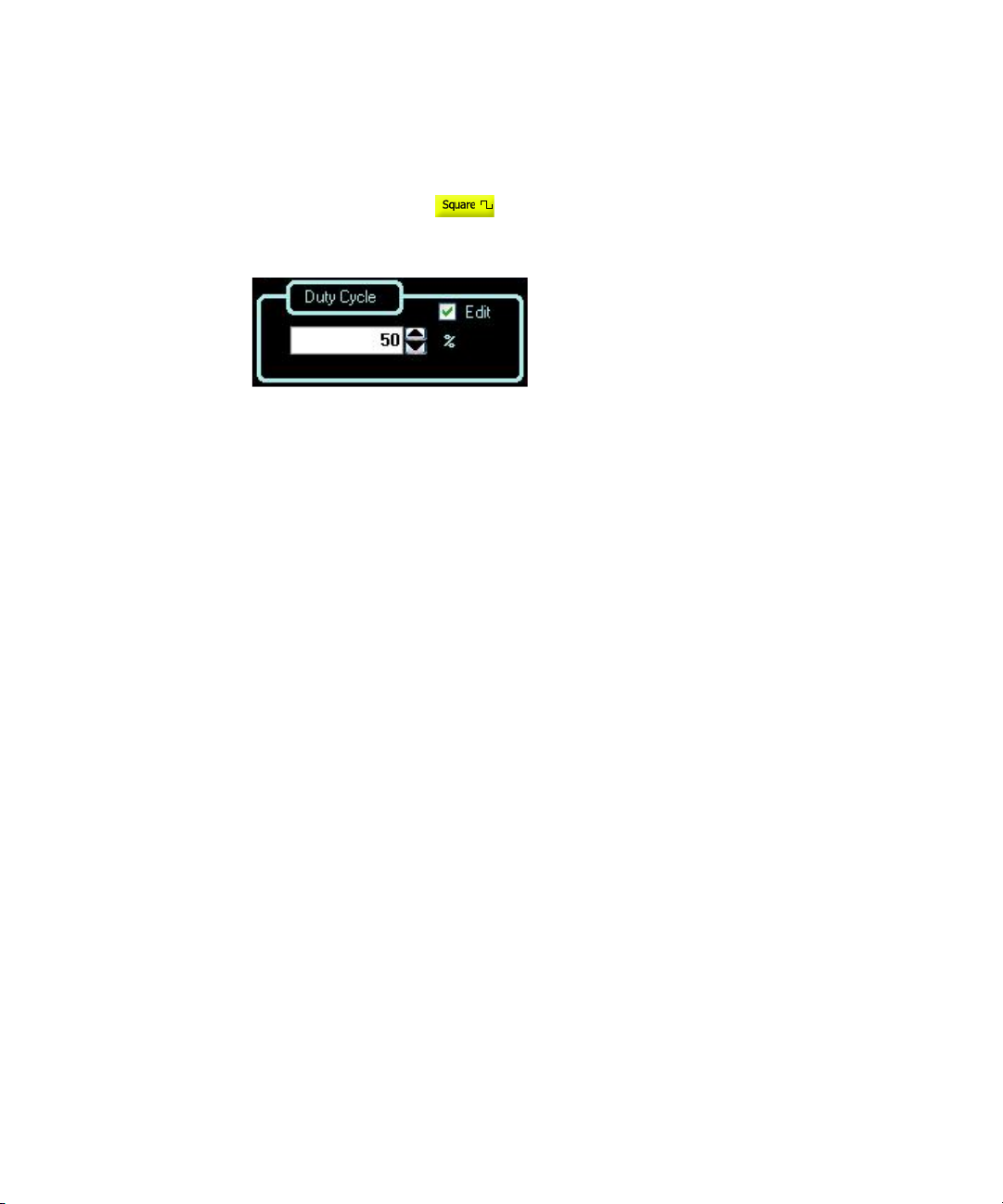
After selecting Square at the top panel as shown in Figure 2-2, on the
Duty Cycle panel below, input the desired duty cycle value.
Figure 2-8 Panel view of the duty cycle section
Remote Interface Operation
The APPLy command automatically sets the duty cycle to 50%.
FUNCtion:SQUare:DCYCle <percent>
46 Keysight U2761A User’s Guide
Page 47
Symmetry (Ramp Wave)
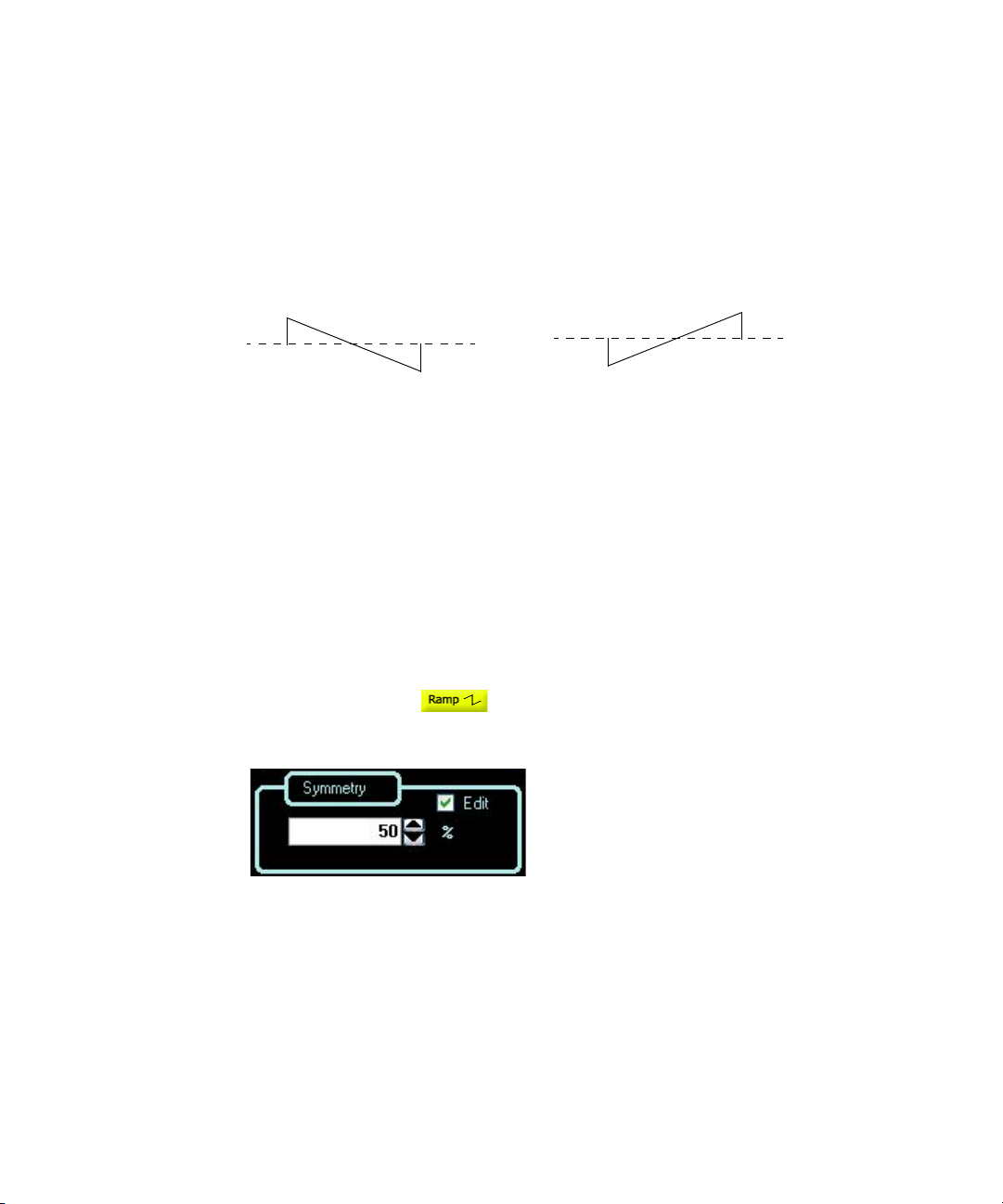
0% Symmetry 100% Symmetry
This configuration applies to Ramp wave only. Symmetry represents the amount
of time per cycle that the Ramp wave is rising (assuming that the waveform is not
inverted).
Figure 2-9 Ramp wave duty cycles
– The symmetry percentage is stored in volatile memory where the symmetry is
set to default 100% upon power-off or after a remote interface reset.
– The symmetry setting is stored when you change from Ramp wave to another
function. Thus, when you return to the Ramp function, the previous symmetry
is used.
– If you select a Ramp waveform as the modulating waveform for AM, FM, or PM,
the symmetry setting does not apply.
Features and Functions 2
Soft Front Panel Operation
After selecting Ramp at the top panel as shown in Figure 2-2, on the
Symmetry panel below, input the desired symmetry value.
Figure 2-10 Panel view of the symmetry section
Keysight U2761A User’s Guide 47
Page 48
2 Features and Functions
Remote Interface Operation
The APPLy command automatically sets the symmetry to 100%.
Output Control
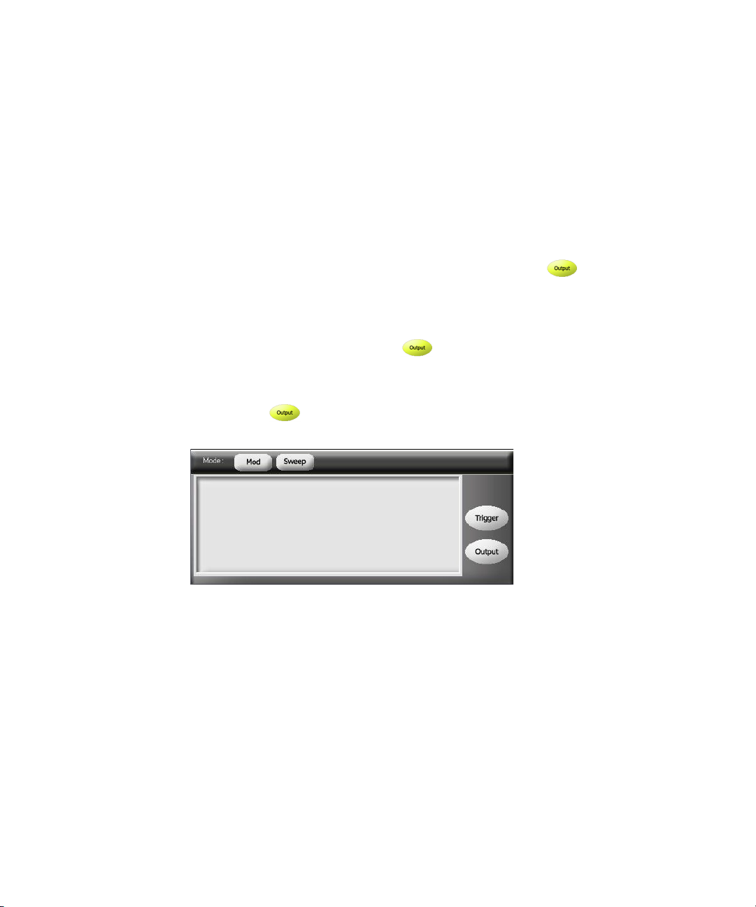
You can disable or enable the soft front panel output control. By default, the
output is disabled at power-on. When enabled, the Output button is
illuminated.
If an excessive external voltage is applied to the device output connector, the
output will be disabled. To re-enable the output, remove the overload from the
output connector and click Output to enable the output.
Soft Front Panel Operation
Click Output to enable or disable the output as shown in Figure 2-11.
FUNCtion:RAMP:SYMMetry <percent>
Figure 2-11 Panel view of the output section
48 Keysight U2761A User’s Guide
Page 49

Remote Interface Operation
OUTPut {0|OFF|1|ON}
The APPLy command overrides the current setting and automatically enables the
output control.
Set Output Using SCPI Commands
The following SCPI commands show a sample procedure of generating output.
Example 1, To output a DC voltage
-> *CLS; *RST // To reset the U2761A to default power-on
-> FUNC DC // Sets the output to DC.
-> VOLT:OFFS 1 // Sets the output DC offset voltage to 1 VDC.
-> OUTP:LOAD INF // Changes the output termination to infinity.
Features and Functions 2
state, this command can be ignored if this
operation is not required.
-> OUTP ON //Turns on output.
Example 2, To output a Sine wave
-> *CLS; *RST //To reset the U2761A to default power-on state,
this command can be ignored if this operation is
not required.
-> FUNC SIN //Sets the output to Sine wave.
-> VOLT 5 VPP //Sets the output amplitude to 5 Vpp.
-> FREQ 1000 //Sets the output frequency to 1 kHz.
-> VOLT:OFFS 0 //Sets the output offset to 0.
-> OUTP ON //Turns on output.
Keysight U2761A User’s Guide 49
Page 50

2 Features and Functions
Example 3, To output a Square wave
-> *CLS; *RST //To reset the U2761A to default power-on
-> APPL:SQU 2000,5 VPP,0 //Sets the output to Square wave, frequency
-> FUNC:SQU:DCYC 30 //Changes the duty cycle to 30%.
-> OUTP ON //Turns on output.
Example 4, To output a Ramp wave
-> *CLS; *RST // To reset the U2761A to default power-on
-> FUNC RAMP // Sets the output to Ramp wave.
state, this command can be ignored if this
operation is not required.
2 kHz, amplitude 5 Vpp, offset 0.
state, this command can be ignored if this
operation is not required.
-> VOLT 5 VPP // Sets the output amplitude to 5 Vpp.
-> FREQ 10000 // Sets the output frequency to 10 kHz.
-> VOLT:OFFS 0 // Sets the output offset to 0.
-> FUNC:RAMP:SYMM 50 // Changes the symmetry to 50%.
-> OUTP ON // Turns on output.
50 Keysight U2761A User’s Guide
Page 51
Pulse Waveform
Pulse width
Period
90% 90%
50% 50%
10%
10%
Rise time
Fall time
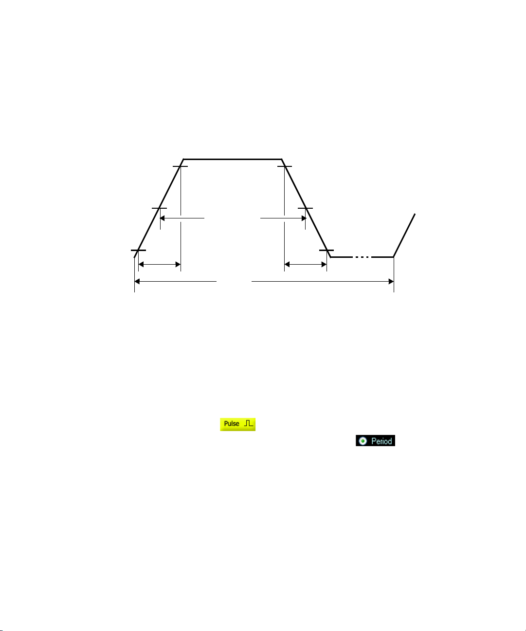
As shown below, a Pulse waveform consists of a period, a pulse width, a rising
edge, and a falling edge.
Figure 2-12 Pulse waveform
Features and Functions 2
Pulse Period
The range of the pulse period is from 200 ns to 2000 s. The default value is 1 ms.
The U2761A will adjusts the pulse width as necessary to accommodate the
specified period.
Soft Front Panel Operation
After selecting Pulse at the top panel as shown in Figure 2-2, on the
Frequency panel as shown in Figure 2-3, select Period , input the desired
pulse period value, and then select the unit from the drop down list.
Remote Interface Operation
Keysight U2761A User’s Guide 51
PULSe:PERiod <seconds>
Page 52
2 Features and Functions
Pulse Width
The pulse width represents the time from the 50% threshold of the pulse’s rising
edge to the 50% threshold of the next falling edge.
– The range of the pulse width is 40 ns to <2000 s (see restrictions below). The
default pulse width is 500
– The minimum pulse width (Wmin) is affected by the period.
Wmin = 40 ns for period ≤ 10 s
Wmin = 200 ns for period > 10 s, but ≤ 100 s
Wmin = 2 μs for period > 100 s, but ≤ 1000 s
Wmin = 20 μs for period > 1000 s
– The specified pulse width must also be less than the difference between the
period and the minimum pulse width as shown in the equation below. The
U2761A will adjusts the pulse width as necessary to accommodate the
specified period.
μ
s.
Pulse Width
≤
Period – Wmin
Soft Front Panel Operation
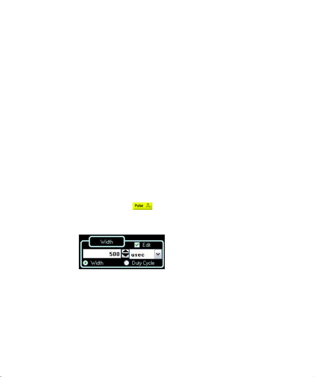
After selecting Pulse at the top panel as shown in Figure 2-2, on the
Width panel below, input the desired pulse width value and select the unit from
the drop down list.
Figure 2-13 Panel view of the pulse wid th section
Remote Interface Operation
FUNCtion:PULSe:WIDTh <seconds>
52 Keysight U2761A User’s Guide
Page 53
Pulse Duty Cycle
The pulse duty cycle is defined as:
Duty Cycle = 100
where the pulse width represents the time from the 50% threshold of the rising
edge of the pulse to the 50% threshold of the next falling edge.
– Pulse duty cycle: >0% to <100% (see restrictions below). The default is 50%.
– The specified pulse duty cycle must conform to the following restrictions
determined by the minimum pulse width (Wmin). The U2761A will adjust the
pulse duty cycle as needed to accommodate the specified period.
×
Pulse Width / Period
Features and Functions 2
Duty Cycle
and
Duty Cycle
where:
Wmin = 40 ns for period ≤ 10 s.
Wmin = 200 ns for period > 10 s, but ≤ 100 s.
Wmin = 2 μs for period > 100 s, but ≤ 1000 s.
Wmin = 20 μs for period > 1000 s.
≥
100 × Wmin / Period
≤
100 × (1 – Wmin / Period)
Soft Front Panel Operation
After selecting Pulse at the top panel as shown in Figure 2-2, select
Duty Cycle as shown in Figure 2-13 and input the desired pulse duty
cycle value on the Duty Cycle panel.
Remote Interface Operation
FUNCtion:PULSe:DCYCle <percent>
Keysight U2761A User’s Guide 53
Page 54

2 Features and Functions
Generate Pulse Waveform Using SCPI Commands
Example 1
-> *CLS; *RST // To reset the Keysight U2761A to default
-> FUNC PULS //Sets the output to Pulse wave.
-> VOLT 5 VPP // Sets the output amplitude to 5 Vpp.
-> VOLT:OFFS 0 //Sets the output offset to 0.
-> PULS:PER 1 // Sets the pulse period to 1 s.
-> FUNC:PULS:DCYC 50 //Set the pulse duty cycle to 50%.
-> OUTP ON //Turns on output.
power-on state, this command can be
ignored if this operation is not required.
54 Keysight U2761A User’s Guide
Page 55
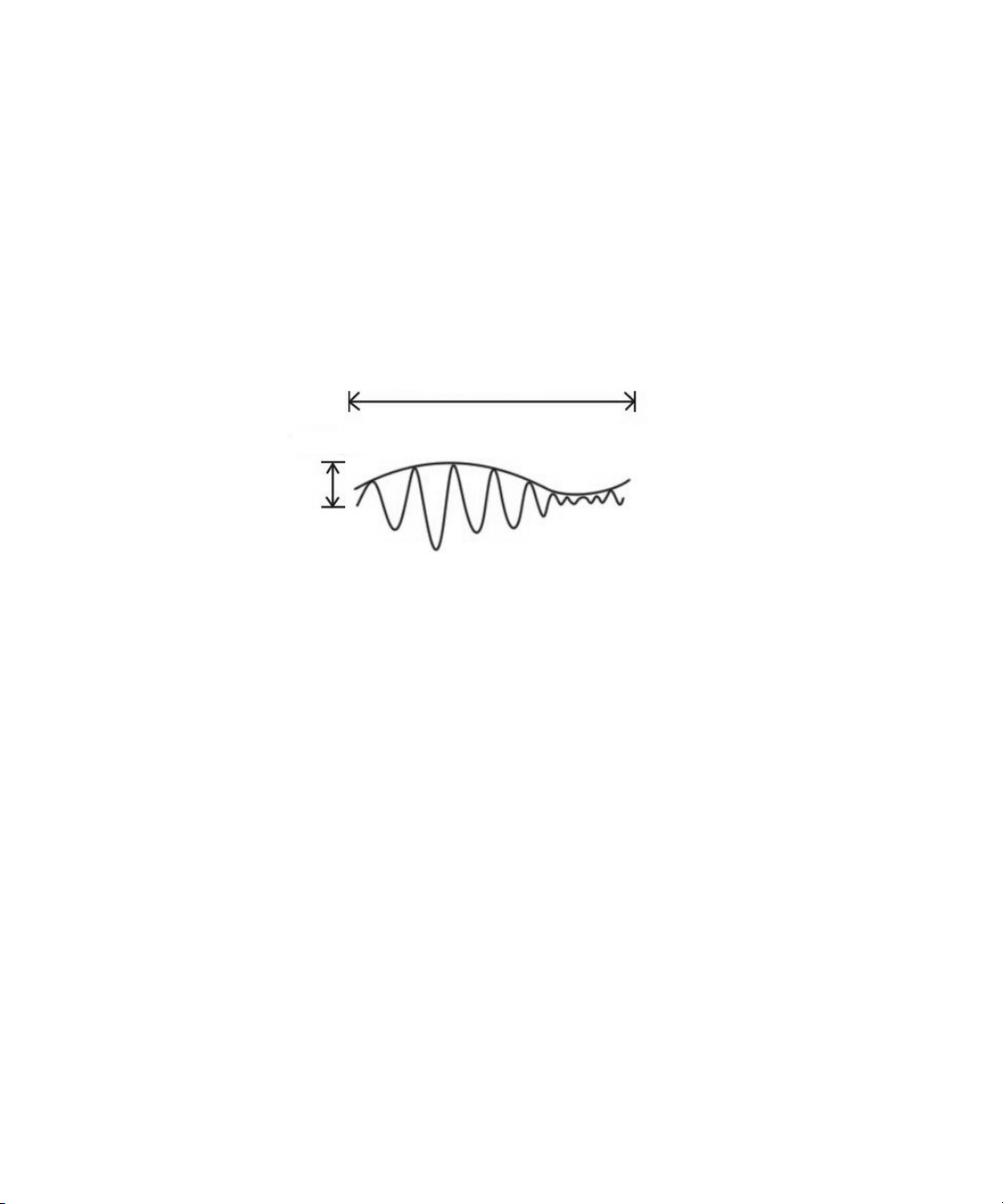
Amplitude Modulation (AM)
Modulating frequency
AM depth
A modulated waveform consists of a carrier waveform and a modulating
waveform. An example of the AM waveform is shown in Figure 2-14. In AM, the
amplitude of the carrier is varied by the instantaneous voltage of the modulating
waveform. The amount of amplitude modulation is called the modulation depth
which refers to the portion of the amplitude range that will be used by the
modulation.
Figure 2-14 AM waveform
Features and Functions 2
To Select AM
The U2761A allows only one modulation mode at a time. The U2761A does not
allow modulation when sweep is enabled.
Keysight U2761A User’s Guide 55
Page 56
2 Features and Functions
Soft Front Panel Operation
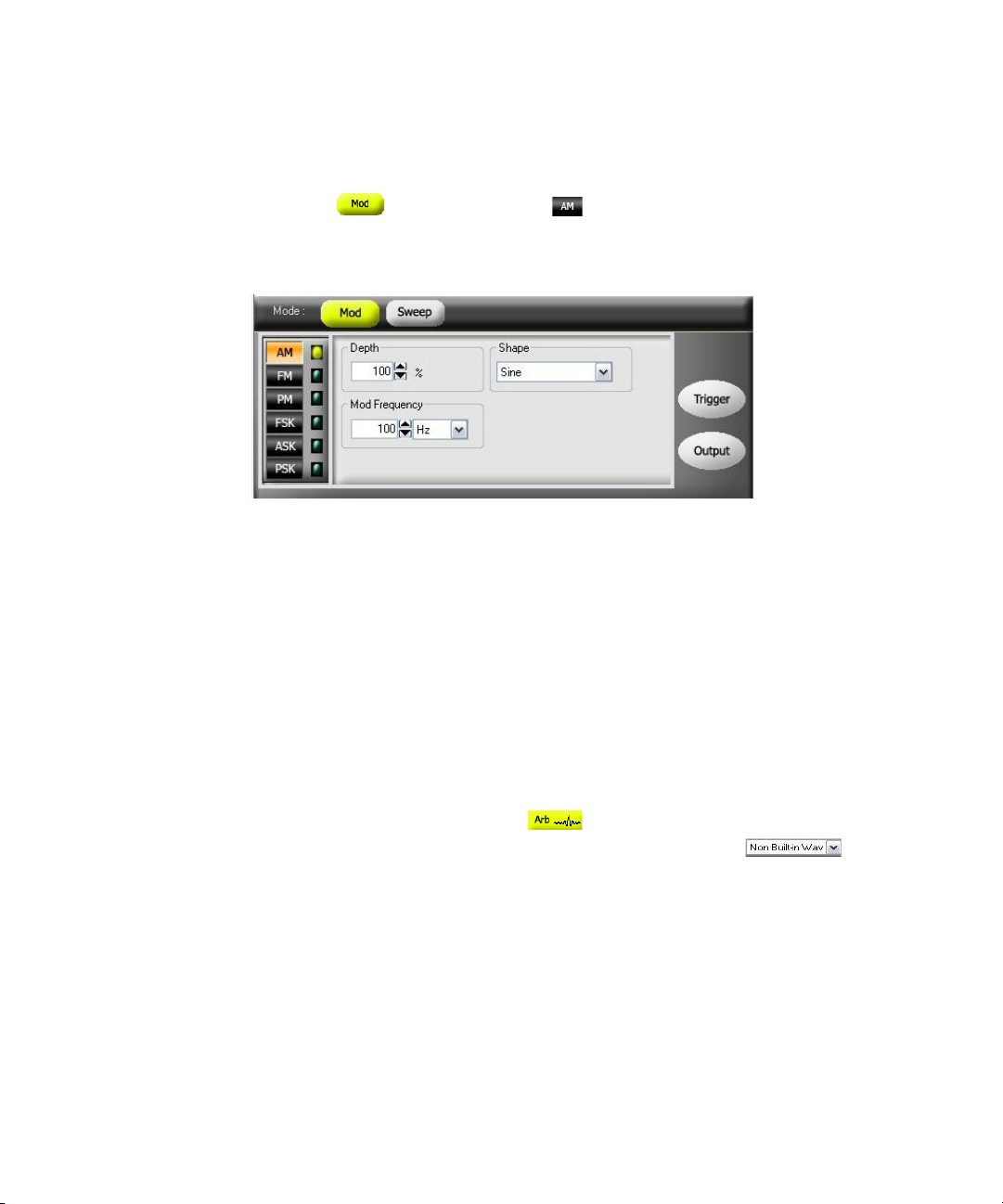
Click Mod and then select AM as shown in Figure 2-15. To output the
AM waveform, configure the settings for the carrier frequency, modulating
frequency, depth, output amplitude, offset voltage, and the desired waveform.
Figure 2-15 Panel view of AM
Remote Interface Operation
AM:STATe {0|OFF|1|ON}
Carrier Waveform
The AM carrier waveform consists of Sine, Square, Ramp, Triangle, or Arbitrary
waveform. The default waveform is Sine wave. You cannot use Pulse or DC as the
carrier waveform.
Soft Front Panel Operation
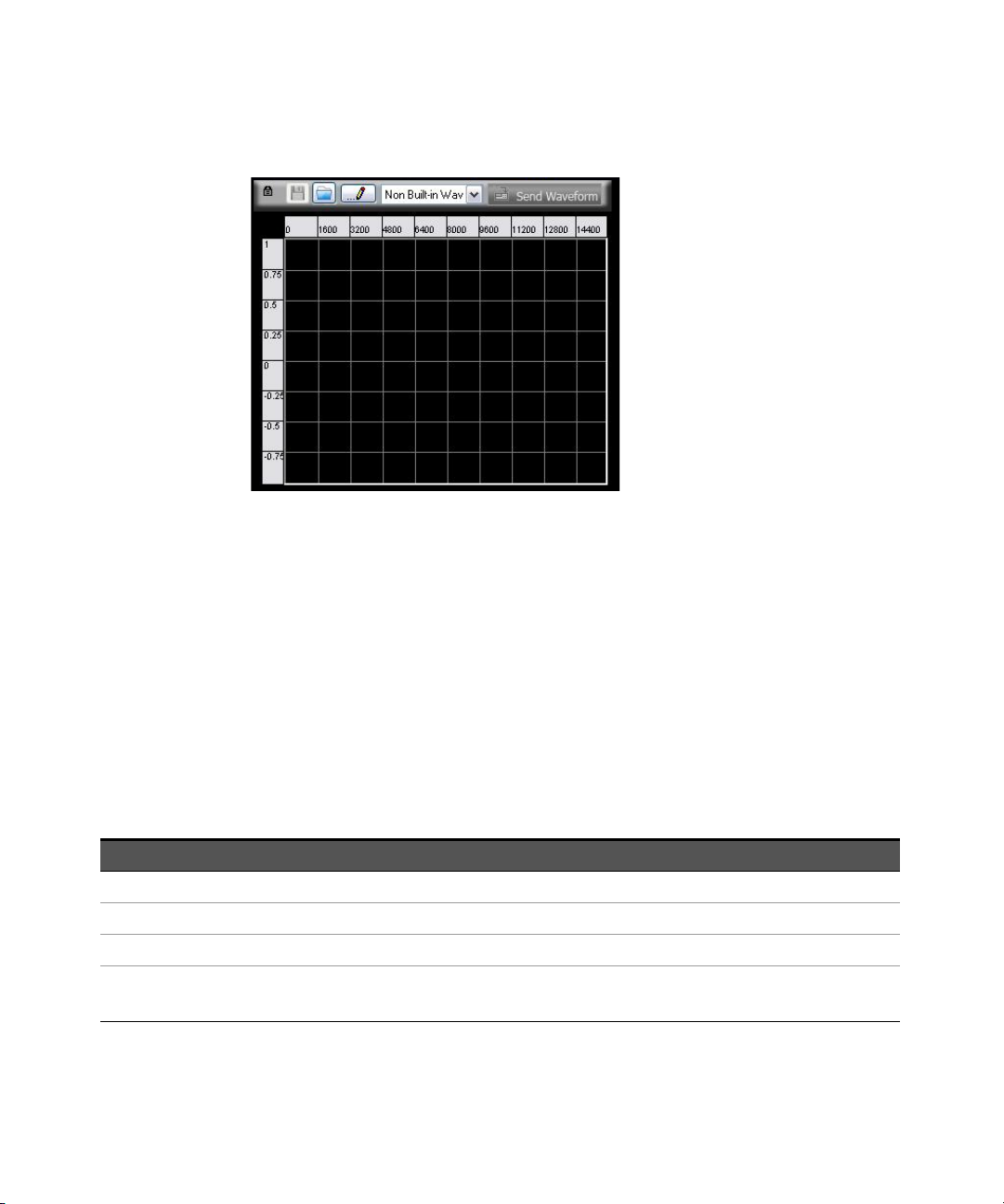
For Arbitrary waveform, select Arb at the top panel as shown in Figure 2-2
and then select the desired waveform from the drop down list as
shown in Figure 2-16.
56 Keysight U2761A User’s Guide
Page 57
Features and Functions 2
Figure 2-16 Panel view of the Arbitrary waveform
Remote Interface Operation
FUNCtion {SINusoid|SQUare|RAMP|USER}
You can also use the APPLy command to select the function, frequency,
amplitude, and offset.
Carrier Frequency
The maximum carrier frequency depends on the selected function as shown
below. The default frequency is 1 kHz for all functions.
Tab le 2-3 Carrier frequency for AM
Function Minimum frequency Maximum frequency
Sine 1 μHz 20 MHz
Square 1 μHz 20 MHz
Ramp, Triangle 1 μHz 200 kHz
Arbitrary 1 μHz 200 kHz
2 MHz (Option U2010A)
Keysight U2761A User’s Guide 57
Page 58

2 Features and Functions
Soft Front Panel Operation
On the Frequency panel as shown in Figure 2-3, input the desired frequency value
and select the unit from the drop down list.
Remote Interface Operation
You can also use the APPLy command to select the function, frequency,
amplitude, and offset.
Modulating Waveform
The modulating waveform consists of Sine, Square, Ramp, Negative Ramp
(Nramp), Triangle, or Arbitrary waveform. The default modulating waveform is
Sine wave.
– Square has 50% duty cycle
– Ramp has 100% symmetry
FREQuency <frequency>
– Triangle has 50% symmetry
– Negative Ramp has 0% symmetry
Soft Front Panel Operation
Select the desired modulating waveform from the drop down list as
shown in Figure 2-15.
Remote Interface Operation
AM:INTernal:FUNCtion
{SINusoid|SQUare|RAMP|NRAMp|TRIangle|USER}
58 Keysight U2761A User’s Guide
Page 59

Modulating Waveform Frequency
NOTE
The range of the modulating waveform frequency is 2 mHz to 20 kHz. The default
modulating waveform frequency is 100 Hz.
Soft Front Panel Operation
On the Mod Frequency panel as shown in Figure 2-15, input the desired
modulating frequency value and select the unit from the drop down list.
Remote Interface Operation
AM:INTernal:FREQuency <frequency>
Modulation Depth
The modulation depth is expressed in percentage and represents the extent of the
amplitude variation. At 0% depth, the output amplitude is half of the selected
value. At 100% depth, the output amplitude equals the selected value.
The range of the modulation depth is 0% to 100%. The default modulation depth
is 100%.
Features and Functions 2
At 100% depth, the maximum output of the U2761A will not exceed ±2.5 V peak
(into a 50 Ω load).
Soft Front Panel Operation
On the Depth panel as shown in Figure 2-15, select the desired modulating depth
value from the drop down list.
Remote Interface Operation
AM:DEPTh <depth in percent>
Keysight U2761A User’s Guide 59
Page 60

2 Features and Functions
Generate AM Using SCPI Commands
Example 1
-> *CLS; *RST // To reset the Keysight U2761A to default
-> AM:STAT ON // Enables AM.
-> FUNC SQU // Sets the carrier waveform to Square
-> FREQ 2000 // Sets the carrier frequency to 2 kHz.
-> VOLT 5 VPP // Sets the output amplitude to 5 Vpp.
-> VOLT:OFFS 0 // Sets the output offset to 0.
-> AM:INT:FUNC SIN // Changes the modulating waveform
-> AM:INT:FREQ 500 // Changes the modulating frequency to
power-on state, this command can be
ignored if this operation is not required.
wave.
shape to Sine wave.
500 Hz.
-> AM:DEPT 50 // Changes the modulation depth to 50%.
-> OUTP ON //Turns on output.
60 Keysight U2761A User’s Guide
Page 61
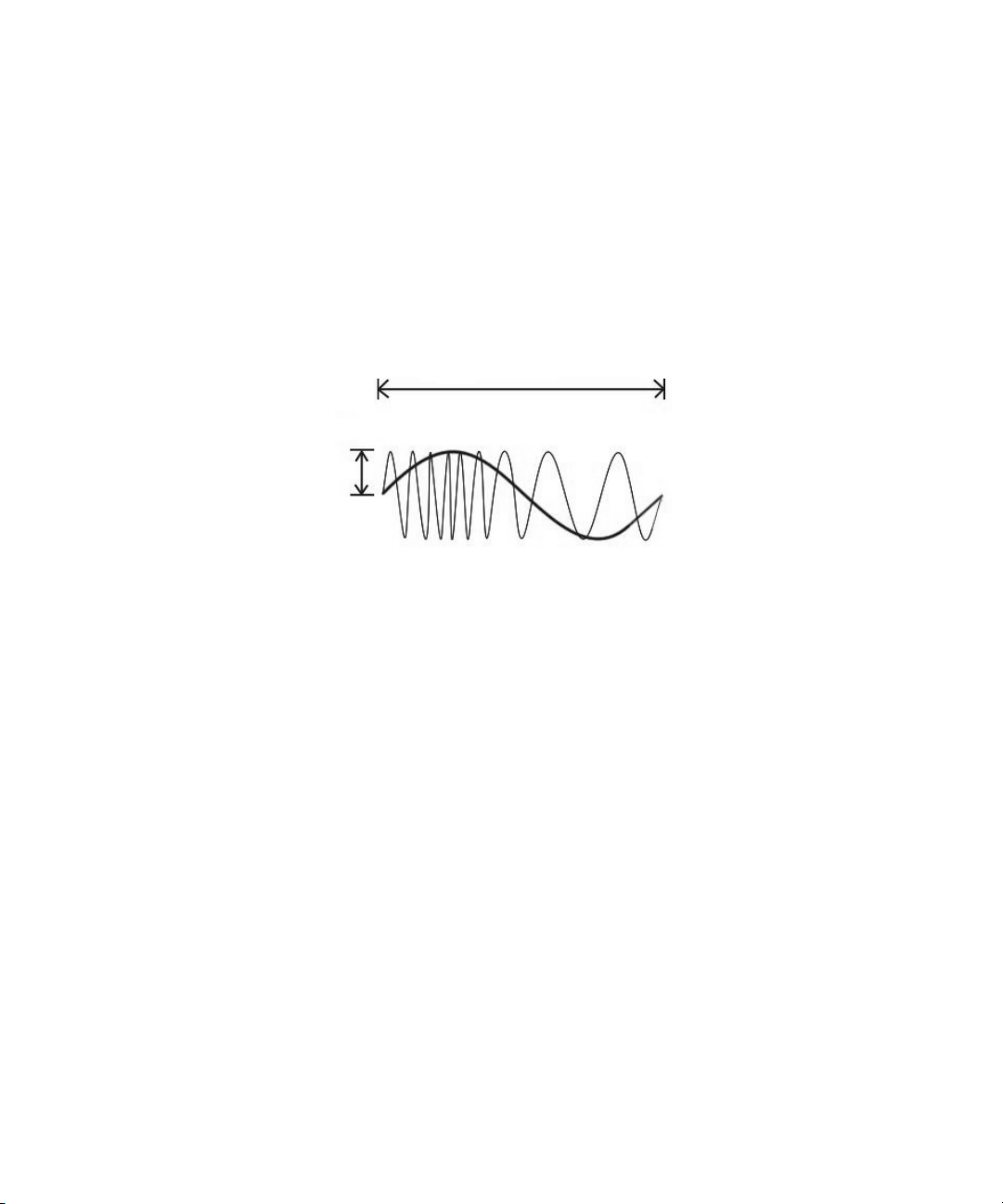
Frequency Modulation (FM)
Modulating frequency
FM deviation
A modulated waveform consists of a carrier waveform and a modulating
waveform. Below shows an example of the FM waveform. In FM, the frequency of
the carrier is varied by the instantaneous voltage of the modulating waveform.
The variation in frequency of the modulated waveform from the carrier frequency
is called the frequency deviation.
Figure 2-17 FM waveform
Features and Functions 2
To Select FM
The U2761A allows only one modulation mode to be enabled at a time. The
U2761A does not allow FM to be enabled at the same time that sweep is enabled.
Keysight U2761A User’s Guide 61
Page 62
2 Features and Functions
Soft Front Panel Operation
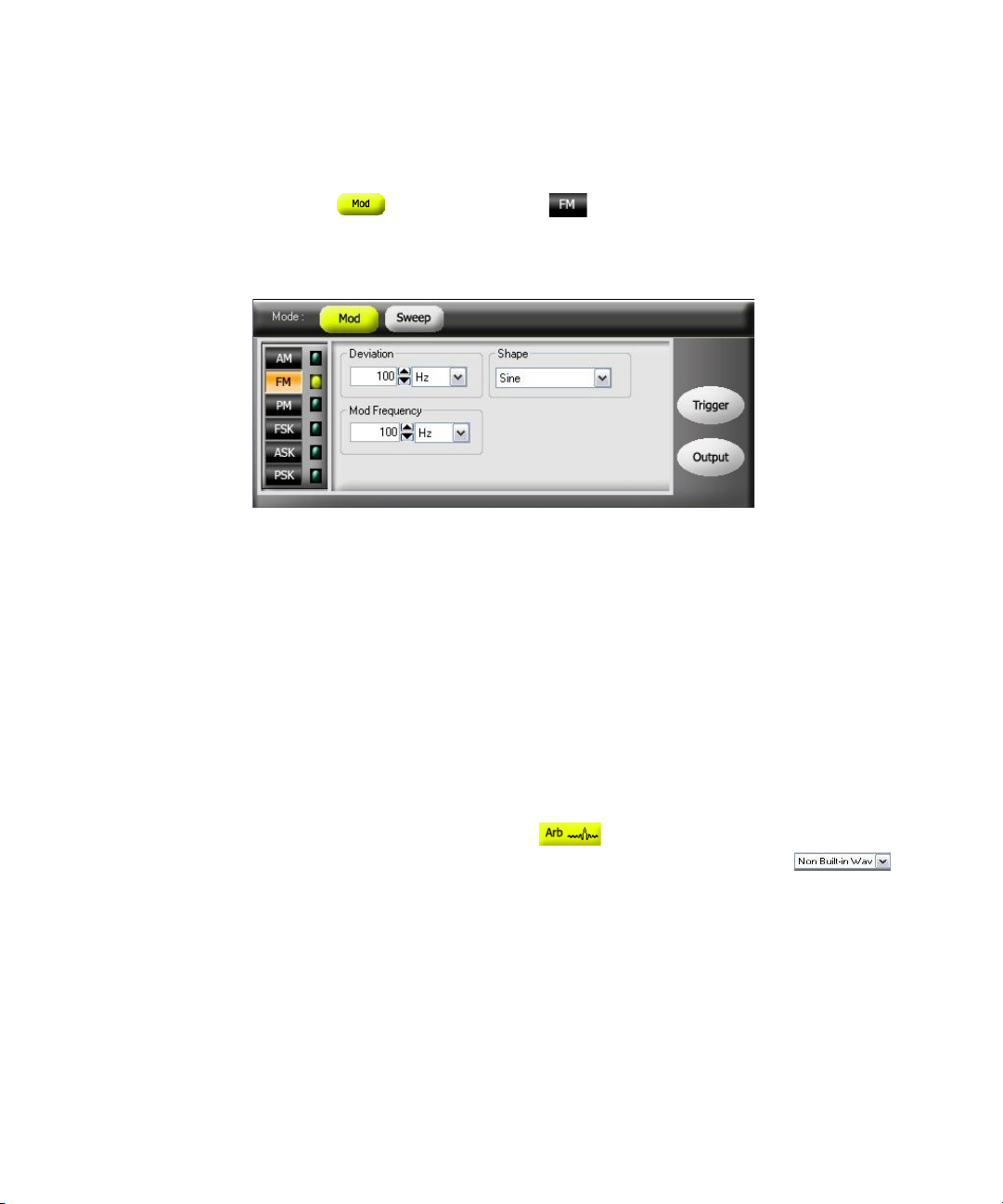
Click Mod and then select FM as shown in Figure 2-18. To output the
FM waveform, configure the settings for the carrier frequency, output amplitude,
offset voltage, modulating frequency, deviation, and the desired waveform.
Figure 2-18 Panel view of FM
Remote Interface Operation
FM:STATe {0|OFF|1|ON}
Carrier Waveform
The FM carrier waveform consists of Sine, Square, Ramp, Triangle, or Arbitrary
waveform. The default waveform is Sine wave. You cannot use Pulse or DC as the
carrier waveform.
Soft Front Panel Operation
For Arbitrary waveforms, select Arb at the top panel as shown in
Figure 2-2 and select the desired waveform from the drop down list
as shown in Figure 2-16.
Remote Interface Operation
FUNCtion {SINusoid|SQUare|RAMP|USER}
You can also use the APPLy command to select the function, frequency,
amplitude, and offset.
62 Keysight U2761A User’s Guide
Page 63

Features and Functions 2
Carrier Frequency
The maximum carrier frequency depends on the selected function as shown
below. The default is 1 kHz for all functions.
Tab le 2-4 Carrier frequency for FM
Function Minimum frequency Maximum frequency
Sine 1 μHz 20 MHz
Square 1 μHz 20 MHz
Ramp, Triangle 1 μHz 200 kHz
Arbitrary 1 μHz 200 kHz
2 Mhz (Option U2010A)
The carrier frequency must always be greater than or equal to the frequency
deviation plus 1 μHz. If you attempt to set the deviation to a value plus 1 μHz
greater than the carrier frequency (with FM enabled), the U2761A will
automatically adjusts the deviation to the maximum value allowed with the
present carrier frequency.
The sum of the carrier frequency and deviation must be less than or equal to the
maximum frequency for the selected function (20 MHz for Sine and Square,
200 kHz for Ramp, and 200 kHz or 2 MHz with option U2010A for Arbitrary
waveforms). If you attempt to set the deviation to a value that is not valid, the
U2761A will automatically adjusts it to the maximum value allowed with the
present carrier frequency.
Soft Front Panel Operation
On the Frequency panel as shown in Figure 2-3, input the desired frequency value
and select the unit from the drop down list.
Remote Interface Operation
FREQuency <frequency>
You can also use the APPLy command to select the function, frequency,
amplitude, and offset.
Keysight U2761A User’s Guide 63
Page 64

2 Features and Functions
Modulating Waveform
The modulating waveform consists of Sine, Square, Ramp, Negative Ramp
(Nramp), Triangle, Noise, or Arbitrary waveform. The default modulating
waveform is Sine wave.
– Square has 50% duty cycle
– Ramp has 100% symmetry
– Triangle has 50% symmetry
– Negative Ramp has 0% symmetry
Soft Front Panel Operation
Select the desired modulating waveform from the drop down list as
shown in Figure 2-18.
Remote Interface Operation
FM:INTernal:FUNCtion
{SINusoid|SQUare|RAMP|NRAMp|TRIangle|USER}
Modulating Waveform Frequency
The range of the modulating waveform frequency is 2 mHz to 20 kHz. The default
modulating waveform frequency is 100 Hz.
Soft Front Panel Operation
On the Mod Frequency panel as shown in Figure 2-18, input the desired
modulating frequency value and select the unit from the drop down list.
Remote Interface Operation
FM:INTernal:FREQuency <frequency>
64 Keysight U2761A User’s Guide
Page 65

Frequency Deviation
The frequency deviation setting represents the peak variation in frequency of the
modulated waveform from the carrier frequency.
The range of the frequency deviation is 1 Hz to 500 kHz (limited to 100 kHz
minus 1 μHz for Ramp and Arbitrary waveforms). The default frequency
deviation is 100 Hz.
The carrier frequency must always be greater than or equal to the frequency
deviation plus 1 μHz. If you attempt to set the deviation to a value plus 1 μHz
greater than the carrier frequency (with FM enabled), the U2761A will
automatically adjusts the deviation to the maximum value allowed with the
present carrier frequency.
The sum of the carrier frequency and deviation must be less than or equal to the
maximum frequency for the selected function (20 MHz for Sine and Square,
200 kHz for Ramp, and 200 kHz or 2 MHz with option U2010A for Arbitrary
waveforms). If you attempt to set the deviation to a value that is not valid, the
U2761A will automatically adjusts it to the maximum value allowed with the
present carrier frequency.
Soft Front Panel Operation
Features and Functions 2
On the Deviation panel as shown in Figure 2-18, input the desired frequency
deviation value and select the unit from the drop down list.
Remote Interface Operation
FM:DEViation <peak deviation in Hz>
Keysight U2761A User’s Guide 65
Page 66

2 Features and Functions
Generate FM Using SCPI Commands
Example 1
-> *CLS; *RST // To reset the Keysight U2761A to default
-> FM:STAT ON // Enables FM.
-> FUNC SIN //Sets the carrier waveform to Sine wave.
-> FREQ 1000 //Sets the carrier frequency to 1 kHz.
-> VOLT 5 VPP // Sets the output amplitude to 5 Vpp.
-> VOLT:OFFS 0 //Sets the output offset to 0.
-> FM:INT:FUNC SIN //Changes the modulating waveform shape
-> FM:INT:FREQ 500 //Changes the modulating frequency to
power-on state, this command can be
ignored if this operation is not required.
to Sine wave.
500 Hz.
-> FM:DEV 100 // Changes the frequency deviation to
100 Hz.
-> OUTP ON //Turns on output.
66 Keysight U2761A User’s Guide
Page 67
Phase Modulation (PM)
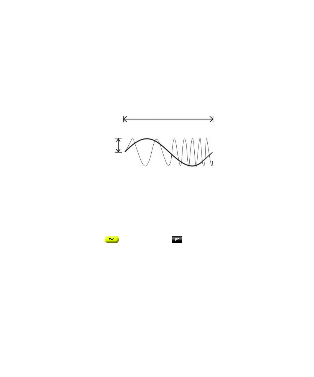
Modulating frequency
Phase deviation
A modulated waveform consists of a carrier waveform and a modulating
waveform. The following figure shows an example of a PM waveform. PM is very
similar to FM, but in PM, the phase of the modulated waveform is varied by the
instantaneous voltage of the modulating waveform. The variation in phase of the
modulated waveform from the carrier waveform is called the phase deviation.
Figure 2-19 PM waveform
To Select PM
Features and Functions 2
Keysight U2761A User’s Guide 67
The U2761A allows only one modulation mode to be enabled at a time. The
U2761A does not allow PM to be enabled at the same time that sweep is enabled.
Soft Front Panel Operation
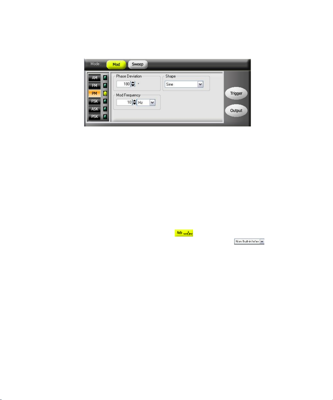
Click Mod and then select PM as shown in Figure 2-20. To output the
PM waveform, configure the settings for the carrier frequency, output amplitude,
offset voltage, modulating frequency, phase deviation, and the desired waveform.
Page 68
2 Features and Functions
Figure 2-20 Panel view of PM
Remote Interface Operation
Carrier Waveform
The PM carrier waveform consists of Sine, Square, Ramp, Triangle, or Arbitrary
waveform. The default waveform is Sine wave. You cannot use Pulse or DC as the
carrier waveform.
PM:STATe {0|OFF|1|ON}
Soft Front Panel Operation
For Arbitrary waveforms, click Arb at the top panel as shown in Figure 2-2
and select the desired waveform from the drop down list as shown in
Figure 2-16.
Remote Interface Operation
FUNCtion {SINusoid|SQUare|RAMP|USER}
You can also use the APPLy command to select the function, frequency,
amplitude, and offset.
68 Keysight U2761A User’s Guide
Page 69

Features and Functions 2
Carrier Frequency
The maximum carrier frequency depends on the function selected as shown
below. The default carrier frequency is 1 kHz for all functions.
Tab le 2-5 Carrier frequency for PM
Function Minimum frequency Maximum frequency
Sine 1 μHz 20 MHz
Square 1 μHz 20 MHz
Ramp, Triangle 1 μHz 200 kHz
Arbitrary 1 μHz 200 kHz
2 Mhz (Option U2010A)
Soft Front Panel Operation
On the Frequency panel as shown in Figure 2-3, input the desired frequency value
and select the unit from the drop down list.
Remote Interface Operation
FREQuency <frequency>
You can also use the APPLy command to select the function, frequency,
amplitude, and offset.
Keysight U2761A User’s Guide 69
Page 70

2 Features and Functions
Modulating Waveform
The modulating waveform consists of Sine, Square, Ramp, Negative Ramp
(Nramp), Triangle, or Arbitrary waveform. The default waveform is Sine wave.
– Square has 50% duty cycle
– Ramp has 100% symmetry
– Triangle has 50% symmetry
– Negative Ramp has 0% symmetry
Soft Front Panel Operation
Select the desired modulating waveform from the drop down list as
shown in Figure 2-20.
Remote Interface Operation
PM:INTernal:FUNCtion
{SINusoid|SQUare|RAMP|NRAMp|TRIangle|USER}
Modulating Waveform Frequency
The range of the modulating waveform frequency is 2 mHz to 20 kHz. The default
modulating waveform frequency is 10 Hz.
Soft Front Panel Operation
On the Mod Frequency panel as shown in Figure 2-20, input the desired
modulating frequency value and select the unit from the drop down list.
Remote Interface Operation
PM:INTernal:FREQuency <frequency>
70 Keysight U2761A User’s Guide
Page 71

Phase Deviation
The phase deviation setting represents the peak variation in phase of the
modulated waveform from the carrier waveform. The phase deviation setting can
be set from 0 to 360°. The default phase deviation setting is 180°.
Soft Front Panel Operation
On the Phase Deviation panel as shown in Figure 2-20, input the desired phase
deviation value.
Remote Interface Operation
PM:DEViation <deviation in degrees>
Generate PM Using SCPI Commands
Example 1
-> *CLS; *RST //To reset the Keysight U2761A to default
Features and Functions 2
power-on state, this command can be
ignored if this operation is not required.
-> PM:STAT ON //Enables PM.
-> FUNC SIN //Sets the carrier waveform to Sine wave.
-> FREQ 1000 // Sets the carrier frequency to 1 kHz.
-> VOLT 5 VPP //Sets the output amplitude to 5 Vpp.
-> VOLT:OFFS 0 //Sets the output offset to 0.
-> PM:INT:FUNC SIN // Changes the modulating waveform shape
to Sine wave.
-> PM:INT:FREQ 500 // Changes the modulating frequency to
500 Hz.
-> PM:DEV 180 //Changes the phase deviation to 180°.
-> OUTP ON //Turns on output.
Keysight U2761A User’s Guide 71
Page 72
2 Features and Functions
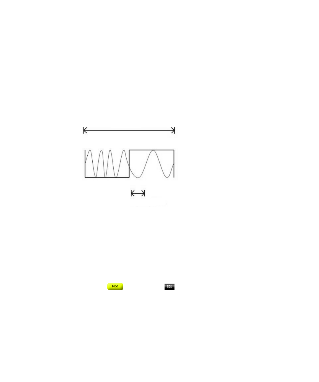
FSK rate
Hop frequency
Frequency-Shift Keying (FSK) Modulation
FSK is similar to FM except that the frequency alternates between two preset
values. You can configure the U2761A to “shift” its output frequency between two
preset values using FSK modulation. An example of the FSK modulation waveform
is shown below. The rate at which the output shifts between the two frequencies
(called the “carrier frequency” and the “hop frequency”) is determined by the
internal rate generator.
Figure 2-21 FSK modulation waveform
To Select FSK Modulation
The U2761A allows only one modulation mode to be enabled at a time. The
U2761A does not allow FSK to be enabled at the same time that sweep is
enabled.
Soft Front Panel Operation
Click Mod and select FSK as shown in Figure 2-22. To output the FSK
72 Keysight U2761A User’s Guide
waveform, configure the settings for the carrier frequency, output amplitude,
offset voltage, “hop frequency”, and FSK rate.
Page 73
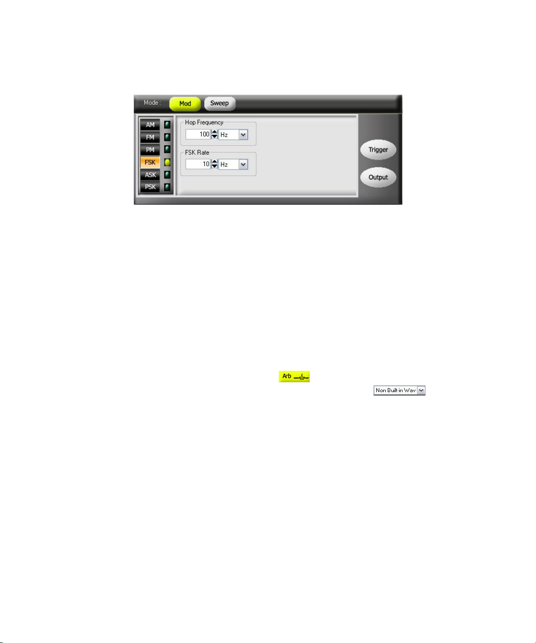
Figure 2-22 Panel view of FSK
Remote Interface Operation
Carrier Waveform
The FSK carrier waveform consists of Sine, Square, Ramp, Triangle, or Arbitrary
waveform. The default carrier waveform is Sine wave. You cannot use Pulse or DC
as the carrier waveform.
Features and Functions 2
FSKey:STATe {0|OFF|1|ON}
Soft Front Panel Operation
For Arbitrary waveforms, click Arb at the top panel as shown in Figure 2-2
and select the desired waveform from the drop down list as shown in
Figure 2-16.
Remote Interface Operation
FUNCtion {SINusoid|SQUare|RAMP|USER}
You can also use the APPLy command to select the function, frequency,
amplitude, and offset.
Keysight U2761A User’s Guide 73
Page 74

2 Features and Functions
FSK Carrier Frequency
The maximum carrier frequency depends on the function selected as shown
below. The default carrier frequency is 1 kHz for all functions.
Tab le 2-6 Carrier frequency for FSK
Function Minimum frequency Maximum frequency
Sine 1 μHz 20 MHz
Square 1 μHz 20 MHz
Ramp, Triangle 1 μHz 200 kHz
Arbitrary 1 μHz 200 kHz
2 Mhz (Option U2010A)
Soft Front Panel Operation
On the Frequency panel as shown in Figure 2-3, input the desired frequency value
and select the unit from the drop down list.
Remote Interface Operation
FREQuency <frequency>
You can also use the APPLy command to select the function, frequency,
amplitude, and offset.
74 Keysight U2761A User’s Guide
Page 75

Features and Functions 2
FSK “Hop” Frequency
The maximum alternate (or “hop”) frequency depends on the function selected as
shown below. The default “hop” frequency is 100 Hz for all functions.
Tab le 2-7 “Hop” frequency
Function Minimum frequency Maximum frequency
Sine 1 μHz 20 MHz
Square 1 μHz 20 MHz
Ramp, Triangle 1 μHz 200 kHz
Arbitrary 1 μHz 200 kHz
2 MHz (Option U2010A)
Only Square wave with a 50% duty cycle is available for the Internal FSK
modulating waveform.
Soft Front Panel Operation
On the Hop Frequency panel as shown in Figure 2-22, input the desired hop
frequency value and select the unit from the drop down list.
Remote Interface Operation
FSKey:FREQuency <frequency>
Keysight U2761A User’s Guide 75
Page 76

2 Features and Functions
FSK Rate
The FSK rate is the rate at which the output frequency “shifts” between the carrier
frequency and the hop frequency.
– The range of the FSK rate is 2 mHz to 100 kHz. The default FSK rate value is
10 Hz.
Soft Front Panel Operation
On the FSK Rate panel as shown in Figure 2-22, input the desired FSK rate value
and select the unit from the drop down list.
Remote Interface Operation
Generate FSK Modulation Using SCPI Commands
Example 1
-> *CLS; *RST // To reset the Keysight U2761A to default
FSKey:INTernal:RATE <rate in Hz>
power-on state, this command can be
ignored if this operation is not required.
-> FSK:STAT ON //Enables FSK modulation.
-> FUNC SIN //Sets the carrier waveform to Sine wave.
-> FREQ 1000 //Sets the carrier frequency to 1 kHz.
-> VOLT 5 VPP // Sets the output amplitude to 5 Vpp.
-> VOLT:OFFS 0 //Sets the output offset to 0.
-> FSK:FREQ 100 //Sets the “hop” frequency to 100 Hz.
-> FSK:INT:RATE 10 // Sets the FSK rate to 10 Hz.
-> OUTP ON //Turns on output.
76 Keysight U2761A User’s Guide
Page 77
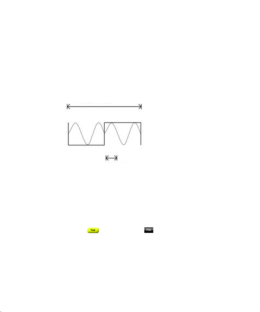
Phase-Shift Keying (PSK) Modulation
PSK rate
PSK deviation
Phase-shift keying (PSK) is a form of digital modulation in which the phase of the
carrier signal is discretely varied. You can configure the U2761A to “shift” its
output phase between two preset phases using PSK. The rate at which the output
shifts between the two phases is determined by the internal rate generator on the
signal level. The following figure shows an example of the PSK modulation
waveform.
Features and Functions 2
Figure 2-23 PSK modulation waveform
To Select PSK Modulation
The U2761A allows only one modulation mode to be enabled at a time. The
U2761A does not allow PSK to be enabled at the same time that sweep is
enabled.
Soft Front Panel Operation
Click Mod and then select PSK as shown in Figure 2-24. To output
the PSK waveform, configure the settings for the carrier frequency, output
Keysight U2761A User’s Guide 77
amplitude, offset voltage, deviation, and PSK rate.
Page 78
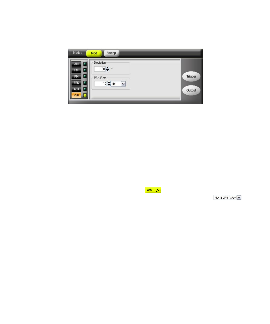
2 Features and Functions
Figure 2-24 Panel view of PSK
Remote Interface Operation
Carrier Waveform
The PSK carrier waveform consists of Sine, Square, Ramp, Triangle, or Arbitrary
waveform. The default waveform is Sine wave. You cannot use Pulse or DC as the
carrier waveform.
PSKey:STATe {0|OFF|1|ON}
Soft Front Panel Operation
For Arbitrary waveforms, select Arb at the top panel as shown in
Figure 2-2 and select the desired waveform from the drop down list
as shown in Figure 2-16.
Remote Interface Operation
FUNCtion {SINusoid|SQUare|RAMP|USER}
You can also use the APPLy command to select the function, frequency,
amplitude, and offset.
78 Keysight U2761A User’s Guide
Page 79

Features and Functions 2
PSK Carrier Frequency
The maximum carrier frequency depends on the function selected as shown
below. The default is 1 kHz for all functions.
Tab le 2-8 Carrier frequency for PSK
Function Minimum frequency Maximum frequency
Sine 1 μHz 20 MHz
Square 1 μHz 20 MHz
Ramp, Triangle 1 μHz 200 kHz
Arbitrary 1 μHz 200 kHz
2 Mhz (Option U2010A)
Only Square wave with a 50% duty cycle is available for the Internal PSK
modulating waveform.
Soft Front Panel Operation
On the Frequency panel shown in Figure 2-3, input the desired frequency value
and select the unit from the drop down list.
Remote Interface Operation
FREQuency <frequency>
You can also use the APPLy command to select the function, frequency,
amplitude, and offset.
Keysight U2761A User’s Guide 79
Page 80

2 Features and Functions
PSK Rate
The PSK rate is the rate at which the output phase “shifts” between two preset
phases. The range of the PSK rate is 2 mHz to 100 kHz. The default PSK rate value
is 10 Hz.
Soft Front Panel Operation
On the PSK Rate panel as shown in Figure 2-24, input the desired PSK rate value
and select the unit from the drop down list.
Remote Interface Operation
PSK Deviation
The deviation setting represents the phase variation of the shifted waveform from
the carrier waveform. The deviation can be set from 0 to 360°. The default
deviation setting is 180°.
Soft Front Panel Operation
PSKey:INTernal:RATE <rate in Hz>
On the Deviation panel as shown in Figure 2-24, input the desired deviation value.
Remote Interface Operation
PSKey:DEViation <deviation in degrees>
80 Keysight U2761A User’s Guide
Page 81

Features and Functions 2
Generate PSK Modulation Using SCPI Commands
Example 1
-> *CLS; *RST // To reset the Keysight U2761A to default
power-on state, this command can be
ignored if this operation is not required.
-> PSK:STAT ON // Enables PSK modulation.
-> FUNC SIN // Sets the carrier waveform to Sine wave.
-> FREQ 1000 // Sets the carrier frequency to 1 kHz.
-> VOLT 5 VPP // Sets the output amplitude to 5 Vpp.
-> VOLT:OFFS 0 // Sets the output offset to 0.
-> PSK:INT:RATE 10 // Sets the PSK rate to 10 Hz.
-> PSK:DEV 180 // Sets the PSK deviation to 180°.
-> OUTP ON // Turns on output.
Keysight U2761A User’s Guide 81
Page 82
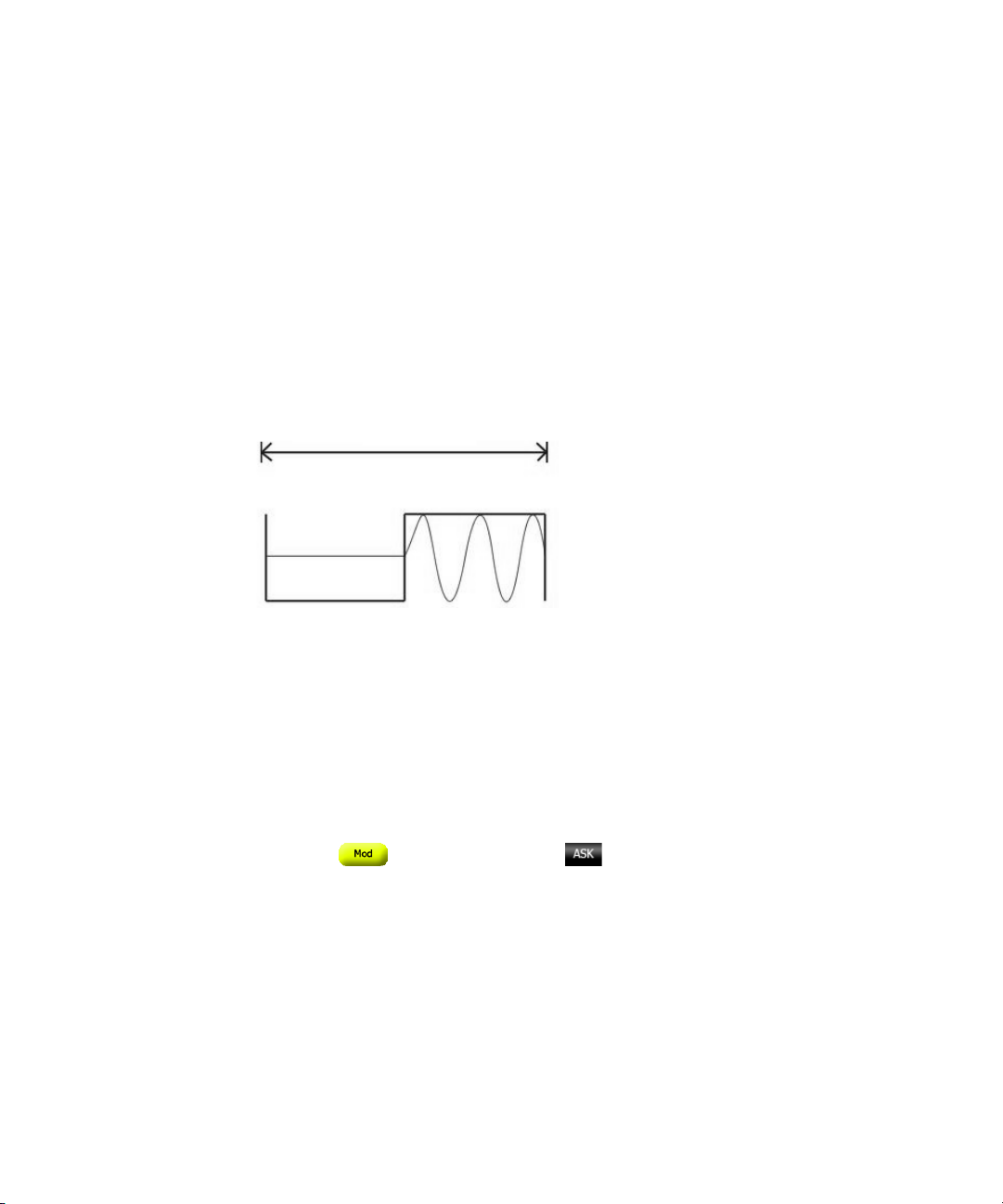
2 Features and Functions
ASK rate
Amplitude-Shift Keying (ASK) Modulation
ASK is a form of digital modulation in which the modulating signal apply
variations in the amplitude of a carrier signal. The amplitude of the carrier signal
varies simultaneously with the modulating signal while phase and frequency
remain constant. In other words, the carrier signal can be assumed as an on and
off switch. You can configure the U2761A to “shift” its output amplitude between
two preset amplitudes using ASK. The rate at which the output shifts between the
two amplitudes is determined by the internal rate generator. An example of the
ASK modulation waveform is shown in the following.
Figure 2-25 ASK modulation waveform
To Select ASK Modulation
The U2761A allows only one modulation mode to be enabled at a time. The
U2761A does not allow ASK to be enabled at the same time that sweep is
enabled.
Soft Front Panel Operation
Click Mod and then select ASK as shown in Figure 2-26. To output
the ASK waveform, configure the settings for the carrier frequency, output
amplitude, offset voltage, and ASK rate.
82 Keysight U2761A User’s Guide
Page 83
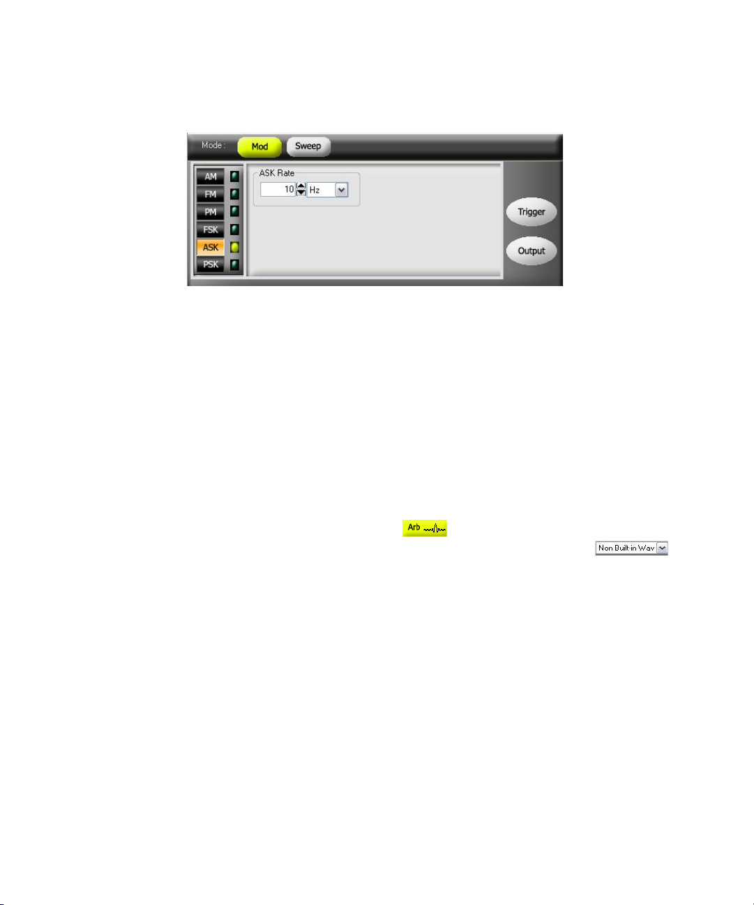
Figure 2-26 Panel view of ASK
Remote Interface Operation
Carrier Waveform
The ASK carrier waveform consists of Sine, Square, Ramp, Triangle, or Arbitrary
waveform. The default waveform is Sine wave. You cannot use Pulse or DC as the
carrier waveform.
Features and Functions 2
ASKey:STATe {0|OFF|1|ON}
Soft Front Panel Operation
For Arbitrary waveforms, select Arb at the top panel as shown in
Figure 2-2 and select the desired waveform from the drop down list
as shown in Figure 2-16.
Remote Interface Operation
FUNCtion {SINusoid|SQUare|RAMP|USER}
You can also use the APPLy command to select the function, frequency,
amplitude, and offset.
Keysight U2761A User’s Guide 83
Page 84

2 Features and Functions
Carrier Frequency
The maximum carrier frequency depends on the function selected as shown
below. The default is 1 kHz for all functions.
Tab le 2-9 Carrier frequency for ASK
Function Minimum frequency Maximum frequency
Sine 1 μHz 20 MHz
Square 1 μHz 20 MHz
Ramp, Triangle 1 μHz 200 kHz
Arbitrary 1 μHz 200 kHz
2 Mhz (Option U2010A)
Only Square wave with a 50% duty cycle is available for the Internal ASK
modulating waveform.
Soft Front Panel Operation
On the Frequency panel as shown in Figure 2-3, input the desired frequency value
and select the unit from the drop down list.
Remote Interface Operation
FREQuency <frequency>
You can also use the APPLy command to select the function, frequency,
amplitude, and offset.
84 Keysight U2761A User’s Guide
Page 85

Features and Functions 2
ASK Rate
The ASK rate is the rate at which the output amplitude “shifts” between two preset
amplitudes. The range of the ASK rate is 2 mHz to 100 kHz. The default ASK rate
value is 10 Hz.
Soft Front Panel Operation
On the ASK Rate panel as shown in Figure 2-26, input the desired ASK rate value
and select the unit from the drop down list.
Remote Interface Operation
ASKey:INTernal:RATE <rate in Hz>
Generate ASK Modulation Using SCPI Commands
Example 1
-> *CLS; *RST // To reset the Keysight U2761A to
default power-on state, this command
can be ignored if this operation is not
required.
-> ASK:STAT ON // Enables ASK modulation.
-> FUNC SIN // Sets the carrier waveform to Sine
wave.
-> FREQ 1000 // Sets the carrier frequency to 1 kHz.
-> VOLT 5 VPP // Sets the output amplitude to 5 Vpp.
-> VOLT:OFFS 0 // Sets the output offset to 0.
-> ASK:INT:RATE 10 // Sets the ASK rate to 10 Hz.
-> OUTP ON // Turns on output.
Keysight U2761A User’s Guide 85
Page 86
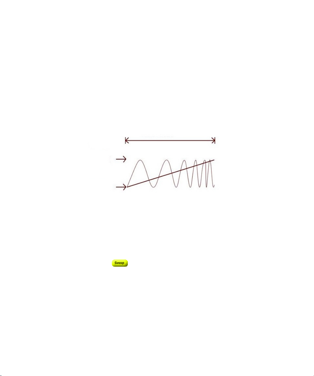
2 Features and Functions
Frequency
Linear type
Start frequency
Stop frequency
Frequency Sweep
In the frequency sweep mode, the U2761A “steps” from the start frequency to the
stop frequency at a sweep rate which you specify. You can sweep up or down in
frequency, and with either linear or logarithmic spacing. You can also configure
the U2761A to output a single sweep (one pass from start frequency to stop
frequency) by applying an External or Manual (software) trigger. The U2761A can
produce a frequency sweep for Sine, Square, Ramp, Triangle, or Arbitrary’s
waveform (Pulse and DC are not allowed). The figure below shows an example of
the frequency sweep.
Figure 2-27 Frequency sweep
To Select Sweep
The U2761A does not allow the sweep mode to be enabled at the same time that
any modulation mode is enabled.
Soft Front Panel Operation
Click Sweep as shown in Figure 2-28. To output sweep, configure the
settings for frequencies, output amplitude, offset, sweep type and time, and
trigger setup.
86 Keysight U2761A User’s Guide
Page 87
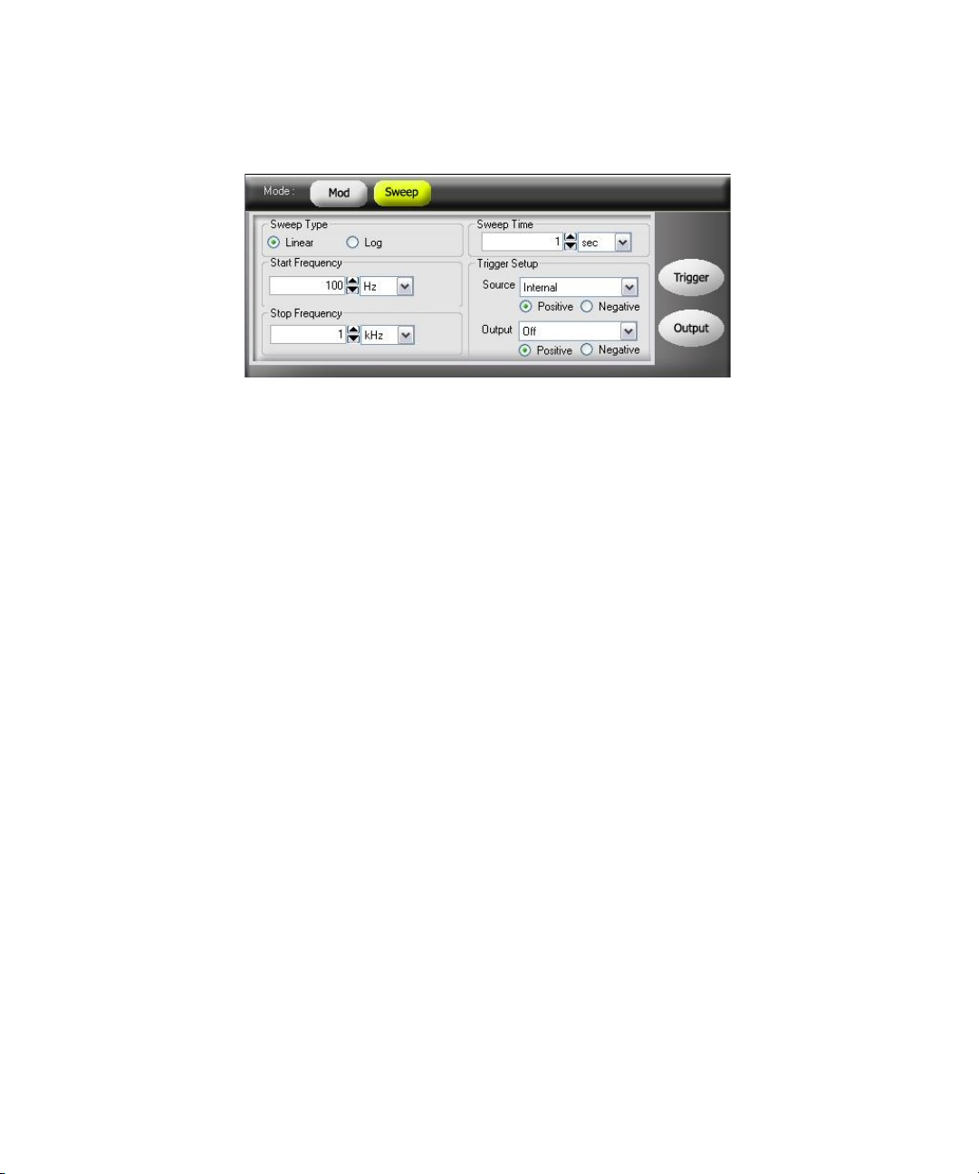
Figure 2-28 Panel view of sweep
Remote Interface Operation
SWEep:STATe {0|OFF|1|ON}
Start Frequency and Stop Frequency
The start frequency and stop frequency sets the upper and lower frequency
bounds for the sweep. The U2761A begins at the start frequency, sweeps to the
stop frequency, and then resets back to the start frequency.
Features and Functions 2
– The range of the start and stop frequencies is 1 μHz to 20 MHz (limited to
200 kHz for Ramp and 200 kHz or 2 MHz with option U2010A for Arbitrary
waveforms). The sweep is phase-continuous over the full frequency range.
The default start frequency is 100 Hz. The default stop frequency is 1 kHz.
–To sweep up in frequency, set the start frequency < stop frequency. To sweep
down in frequency, set the start frequency > stop frequency.
Soft Front Panel Operation
On the Start Frequency and Stop Frequency panels as shown in Figure 2-28, input
the desired start frequency and stop frequency values and select the respective
units from the drop down lists.
Remote Interface Operation
FREQuency:STARt <frequency>
FREQuency:STOP <frequency>
Keysight U2761A User’s Guide 87
Page 88

2 Features and Functions
Sweep Mode
You can sweep with either linear or logarithmic spacing. For a linear sweep, the
U2761A varies the output frequency in a linear fashion during the sweep. For a
logarithmic sweep, the U2761A varies the output frequency in a logarithmic
fashion.
The sweep mode consists of Linear or Logarithmic. The default sweep mode is
Linear.
Soft Front Panel Operation
On the Sweep Type panel as shown in Figure 2-28, select the Linear or
Log mode.
Remote Interface Operation
Sweep Time
The sweep time specifies the number of seconds required to sweep from the start
frequency to the stop frequency. The number of discrete frequency points in the
sweep is automatically calculated by the U2761A and is based on the sweep time
you have selected. The range of the sweep time is 1 ms to 500 s. The default
sweep time is 1 s.
SWEep:SPACing {LINear|LOGarithmic}
Soft Front Panel Operation
On the Sweep Time panel as shown in Figure 2-28, input the desired sweep time
and select the unit from the drop down list.
Remote Interface Operation
SWEep:TIME <seconds>
88 Keysight U2761A User’s Guide
Page 89
Sweep Trigger Source
In the sweep mode, the U2761A outputs a single sweep when a trigger signal is
received. After one sweep from the start frequency to the stop frequency, the
U2761A will continuously output the preset waveform at the start frequency while
waiting for the next trigger.
– The sweep trigger source consists of Internal (immediate), External, or Manual
(software). The default trigger source is Internal.
–When the Internal source is selected, the U2761A outputs a continuous sweep
at a rate determined by the specified sweep time.
–When the External source is selected, the U2761A accepts a hardware trigger
applied to the device Trig In connector. The U2761A initiates one sweep each
time Trig In receives a TTL pulse with the specified polarity.
–When the Manual source is selected, the U2761A outputs one sweep each
time the soft front panel Trigger is clicked.
Soft Front Panel Operation
On the Trigger Setup panel as shown in Figure 2-28, select the desired sweep
trigger source from the drop down list at the Source panel.
Features and Functions 2
To specify whether the U2761A is triggered on the rising or falling edge of the
signal from the Trig In connector, select Positive for rising edge
triggering and Negative for falling edge triggering.
Remote Interface Operation
TRIGger:SOURce {IMMediate|EXTernal|BUS}
Use the following command to specify whether the U2761A is triggered on the
rising or falling edge of the signal from the Trig In connector.
TRIGger:SLOPe {POSitive|NEGative}
Keysight U2761A User’s Guide 89
Page 90

2 Features and Functions
Set Frequency Sweep Using SCPI Commands
Example 1
-> *CLS; *RST //To reset the Keysight U2761A to default
-> FUNC SIN //Sets the carrier waveform to Sine wave.
-> VOLT 5 VPP //Sets the output amplitude to 5 Vpp.
-> VOLT:OFFS 0 //Sets the output offset to 0.
-> SWE:STAT ON //Enables frequency sweep.
-> FREQ:STAR 500 //Changes the start frequency to 500 Hz.
-> FREQ:STOP 10000 //Changes the stop frequency to 10 kHz.
-> SWE:SPAC LIN //Changes the sweep mode to Linear.
-> SWE:TIME 2 //Changes the sweep time to 2 s.
-> TRIG:SOUR EXT //Changes the sweep trigger source to
power-on state, this command can be
ignored if this operation is not required.
External.
-> TRIG:SLOP POS //Changes the U2761A to be triggered on
the rising edge.
-> OUTP ON //Turns on output.
90 Keysight U2761A User’s Guide
Page 91

Triggering
Trigger Source Choices
Features and Functions 2
Applies to sweep only. You can issue triggers for sweeps using Internal
(immediate) triggering, External triggering, or Manual (software) triggering.
– Internal triggering is enabled when you turn on the U2761A. In this mode, the
U2761A outputs continuously when the sweep mode is selected.
– External triggering uses the device Trig In connector to control the sweep. The
U2761A initiates one sweep each time Trig In receives a TTL pulse. You can
select whether the U2761A is triggered on the rising or falling edge of the
External trigger signal.
– Manual triggering initiates one sweep each time you click Trigger on the
soft front panel.
You must specify the source from which the U2761A accepts a trigger.
– The sweep trigger source consists of Internal, External, or Manual. The default
trigger source is Internal.
– The U2761A accepts a Manual trigger, a hardware trigger from the device Trig
In connector, or continuously output sweeps using an Internal trigger. At
power-on, Internal trigger is selected.
– The trigger source setting is stored in volatile memory where the source is set
to Internal (immediate) trigger upon power-off or after a remote interface
reset.
Soft Front Panel Operation
On the Trigger Setup panel as shown in Figure 2-28, select the desired trigger
source from the drop down list at the Source panel.
Remote Interface Operation
TRIGger:SOURce {IMMediate|EXTernal|BUS}
Keysight U2761A User’s Guide 91
Page 92
2 Features and Functions
Internal Triggering
In the Internal trigger mode, the U2761A continuously performs frequency sweep
(as specified by the sweep time). This is the default trigger source for both soft
front panel and remote interface use.
Soft Front Panel Operation
On the Trigger Setup panel as shown in Figure 2-28, select Internal from the drop
down list at the Source panel.
Remote Interface Operation
Manual Triggering
In the Manual (software) triggering mode, you can manually trigger the U2761A
by clicking Trigger . The U2761A initiates one sweep each time you click
the button. The Trigger button is illuminated while the U2761A waits for a
Manual trigger.
TRIGger:SOURce IMMediate
Soft Front Panel Operation
On the Trigger Setup panel as shown in Figure 2-28, select Manual from the drop
down list at the Source panel.
Remote Interface Operation
TRIGger:SOURce BUS
When the BUS source is selected, send the TRIG or *TRG command to trigger the
U2761A.
92 Keysight U2761A User’s Guide
Page 93

External Triggering
In the External trigger mode, the U2761A accepts a hardware trigger applied to
the device Trig In connector. The U2761A initiates one sweep each time Trig In
receives a TTL pulse with the specified edge.
Also refer to “Trigger Input Signal” on page 94.
Soft Front Panel Operation
On the Trigger Setup panel as shown in Figure 2-28, select External from the drop
down list at the Source panel.
To specify whether the U2761A is triggered on the rising or falling edge, select
Positive for triggering on the rising edge and Negative for
triggering on the falling edge.
Remote Interface Operation
Use the following command to specify whether the U2761A is triggered on the
rising or falling edge.
Features and Functions 2
TRIGger:SOURce EXTernal
TRIGger:SLOPe {POSitive|NEGative}
Keysight U2761A User’s Guide 93
Page 94
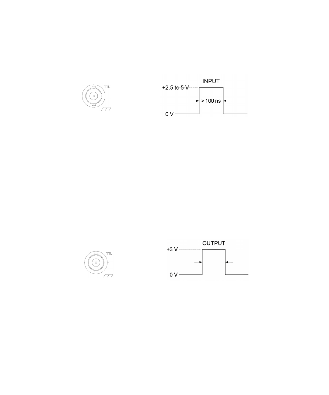
2 Features and Functions
Trigger in
Rising edge shown
Trigger out
Rising edge shown
> 500 μs
Trigger Input Signal
Figure 2-29 Trigger input pulse
The device connector is used for Triggered Sweep Mode, refer to “Sweep Trigger
Source” on page 89. When the rising or falling edge of the TTL pulse is received
on the Trig In connector, the U2761A outputs a single sweep, refer to “External
Triggering” on page 93.
Trigger Output Signal
A “trigger out” signal is provided on the device Trig Out connector (used with
sweep only). When enabled, a TTL-compatible Square waveform with either a
rising (default) or falling edge is output to the device Trig Out connector at the
beginning of the sweep.
Figure 2-30 Trigger output pulse
When the Internal (immediate) trigger source is selected, the U2761A outputs a
Square waveform with a 50% duty cycle to the Trig Out connector at the
beginning of the sweep. The period of the Square waveform is equal to the
specified sweep time.
94 Keysight U2761A User’s Guide
Page 95

Features and Functions 2
When the Manual (software) trigger source is selected, the U2761A outputs a
pulse to the Trig Out connector at the beginning of each sweep.
Soft Front Panel Operation
After enabling sweep, to specify whether the Keysight U2761A outputs a
TTL-compatible Square waveform with either a rising or falling edge, select
Positive for rising edge and Negative for falling edge.
Remote Interface Operation
OUTPut:TRIGger {0|OFF|1|ON}
OUTPut:TRIGger:SLOPe {POSitive|NEGative}
Keysight U2761A User’s Guide 95
Page 96

2 Features and Functions
Set Triggering Using SCPI Commands
Example 1
-> *CLS; *RST //To reset the Keysight U2761A to default
-> FUNC SIN //Sets the carrier waveform to Sine wave.
-> VOLT 5 VPP //Sets the output amplitude to 5 Vpp.
-> VOLT:OFFS 0 // Sets the output offset to 0.
-> SWE:STAT ON // Enables frequency sweep.
-> FREQ:STAR 500 //Changes the start frequency to 500 Hz.
-> FREQ:STOP 10000 // Changes the stop frequency to 10 kHz.
-> SWE:SPAC LIN //Changes the sweep mode to Linear.
-> SWE:TIME 2 //Changes the sweep time to 2 s.
-> TRIG:SOUR IMM //Changes the sweep trigger source to
-> OUTP:TRIG ON //Turns on the trigger output.
-> OUTP:TRIG:SLOP POS //Outputs the trigger on a rising edge.
-> OUTP ON //Turns on output.
power-on state, this command can be
ignored if this operation is not required.
Internal.
96 Keysight U2761A User’s Guide
Page 97
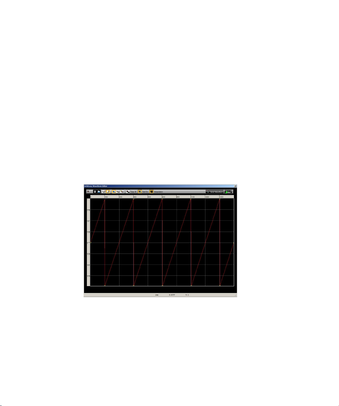
Arbitrary Waveforms
There are three built-in Arbitrary waveforms offered. The U2761A supports the
Arbitrary waveform up to 65536 (64K) data points. You can create an Arbitrary
waveform using the soft front panel as described in the following. For further
information, please refer to the Keysight Measurement Manager help file.
To Create and Store an Arbitrary Waveform
This section provides you an example on the procedure to create and store an
Arbitrary waveform using the soft front panel. To create an Arbitrary waveform
remotely, refer to the Keysight U2761A USB Modular Function/Waveform
Generator Programmer’s Reference. You will create and store the Ramp waveform
shown below as an example.
Amplitude = 2 Vpp, Period = 10 ms
Features and Functions 2
Figure 2-31 Ramp waveform
Keysight U2761A User’s Guide 97
Page 98
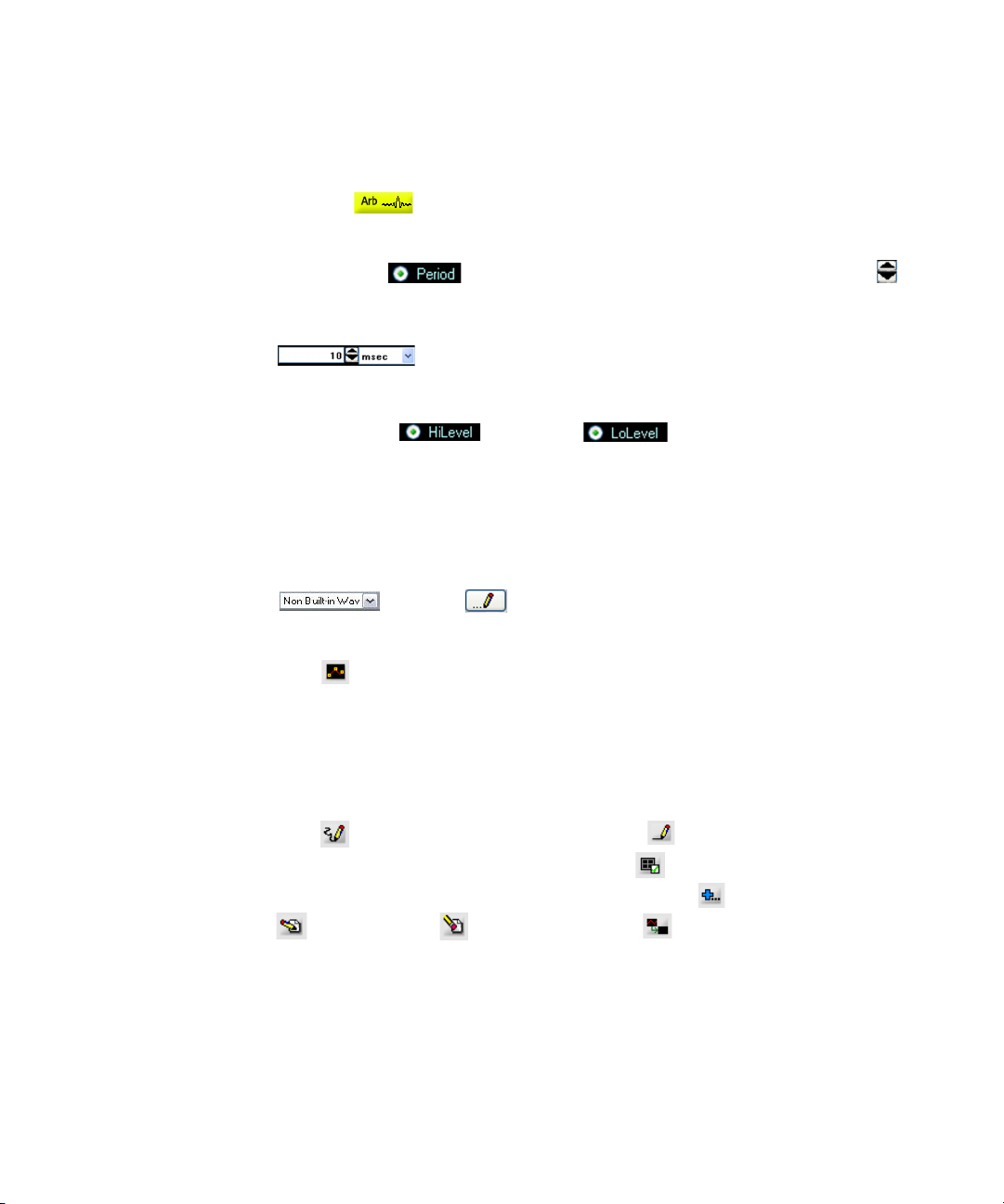
2 Features and Functions
1 Select the Arbitrary waveform function.
Click Arb to select the Arbitrary function.
2 Set the waveform period.
Select Period and use the numeric keypad or numeric drop down
to set the period for the waveform.
For example, set the period of the waveform to 10 ms.
3 Set the waveform voltage limits.
Select HiLevel and Lolevel to set the high and low
voltage levels that can be reached while editing the waveform. The upper limit
must be greater than the lower limit.
For example, set the upper limit to 2.0 V and the lower limit to 0 V.
4 Start the Arbitrary waveform editor.
Select Non Built-in Waveform from the Arbitrary’s drop down list
and click to start the Arbitrary waveform editor.
5 Select the interpolation method.
Click to enable or disable linear interpolation between the user-defined
points. With interpolation enabled (default), the waveform editor makes a
straight-line connection between the points. With interpolation disabled, the
waveform editor maintains a constant voltage level between the points and
creates a “step-like’ waveform.
6 Start waveform ed iting process.
Click to begin the freehand draw mode or to enable line draw mode.
To enable or disable the grid reference, click . Then, start drawing the
desired waveform. To edit the waveform, click either to add line/point(s),
to edit point(s), to delete point(s), or to clear current Arbitrary
graph.
98 Keysight U2761A User’s Guide
Page 99
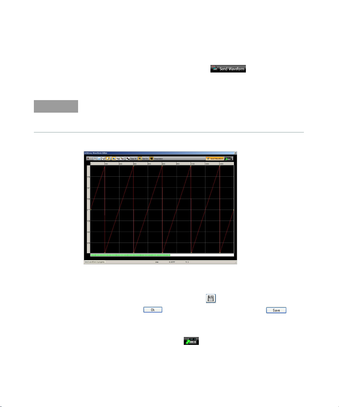
Features and Functions 2
NOTE
7 Send ing waveform to the U2761A.
To send the waveform to the U2761A, click . Once the Send
waveform in progress has completed, the Send waveform has completed
message is displayed.
The downloading of an Arbitrary waveform may take up to several minutes. The
status bar at the bottom of the Arbitrary waveform editor window shows the
progress of the download. Please wait for the Send waveform has completed
message to be displayed before proceeding with the next step.
Figure 2-32 Waveform download in progress
8Saving the waveform.
To save the waveform for future use, click . Then, select Compatible With
Intuilink and click . Input the desired file name and click to
save the file.
9 Exiting the waveform ed itor.
To exit the waveform editor, click .
Keysight U2761A User’s Guide 99
Page 100

2 Features and Functions
THIS PAGE HAS BEEN INTENTIONALLY LEFT BLANK.
100 Keysight U2761A User’s Guide
 Loading...