

Page 1

Test Equipment Depot - 800.517.8431 - 99 Washington Street Melrose, MA 02176 - TestEquipmentDepot.com
Keysight U2741A USB
Modular 5.5 Digits Digital
Multimeter
User’s Guide
Page 2

Notices
CAUTION
WARNING
Copyright Notice
© Keysight Technologies 2008 - 2017
No part of this manual may be
reproduced in any form or by any
means (including electronic storage
and retrieval or translation into a
foreign language) without prior
agreement and written consent from
Keysight Technologies as governed by
United States and international
copyright laws.
Manual Part Number
U2741-90001
Edition
Edition 10, March 17, 2017
Printed in:
Printed in Malaysia
Published by:
Keysight Technologies
Bayan Lepas Free Industrial Zone,
11900 Penang, Malaysia
Technology Licenses
The hardware and/or software
described in this document are
furnished under a license and may be
used or copied only in accordance with
the terms of such license.
Declaration of Conformity
Declarations of Conformity for this
product and for other Keysight
products
Web.
may be downloaded from the
U.S. Government Rights
The Software is “commercial computer
software,” as defined by Federal
Acquisition Regulation (“FAR”) 2.101.
Pursuant to FAR 12.212 and 27.405-3
and Department of Defense FAR
Supplement (“DFARS”) 227.7202, the
U.S. government acquires commercial
computer software under the same
terms by which the software is
customarily provided to the public.
Accordingly, Keysight provides
Software to U.S. government
customers under its standard
commercial license, which is embodied
its End User License Agreement
in
(EULA). The license set forth in the
EULA represents the exclusive
authority by which the U.S.
government may use, modify,
distribute, or disclose the Software.
The EULA and the license set forth
therein, does not require or permit,
among other things, that Keysight: (1)
Furnish technical
information related to commercial
computer software or commercial
computer software documentation that
is not customarily provided to the
public; or (2) Relinquish to, or
otherwise provide, the government
rights in excess of these rights
customarily provided to the public to
use, modify, reproduce, release,
perform, display, or disclose
commercial computer software or
commercial computer software
documentation. No additional
government requirements beyond
those set forth in the EULA shall apply,
except to the extent that those terms,
rights, or licenses are explicitly required
from all providers of commercial
computer software pursuant to the FAR
and the DFARS and are set forth
specifically in writing elsewhere in the
EULA. Keysight shall be under no
obligation to update, revise or
otherwise modify the Software. With
respect to any technical data as
defined by FAR 2.101, pursuant to FAR
12.211 and 27.404.2 and DFARS
227.7102, the U.S. government
acquires no greater than Limited Rights
as defined in FAR 27.401 or DFAR
227.7103-5 (c), as applicable in any
technical data.
the
Warranty
THE MATERIAL CONTAINED IN THIS
DOCUMENT IS PROVIDED “AS IS,”
AND IS SUBJECT TO BEING
CHANGED, WITHOUT NOTICE, IN
FUTURE EDITIONS. FURTHER, TO THE
MAXIMUM EXTENT PERMITTED BY
APPLICABLE LAW, KEYSIGHT
DISCLAIMS ALL WARRANTIES, EITHER
EXPRESS OR IMPLIED, WITH REGARD
TO THIS MANUAL AND ANY
INFORMATION CONTAINED HEREIN,
INCLUDING BUT NOT LIMITED TO THE
IMPLIED WARRANTIES OF
MERCHANTABILITY AND FITNESS FOR
A PARTICULAR PURPOSE. KEYSIGHT
SHALL NOT BE LIABLE FOR ERRORS
OR FOR INCIDENTAL OR
CONSEQUENTIAL DAMAGES IN
CONNECTION WITH THE
FURNISHING, USE, OR
PERFORMANCE OF THIS DOCUMENT
OR OF ANY INFORMATION
CONTAINED HEREIN. SHOULD
KEYSIGHT AND THE USER HAVE A
SEPARATE WRITTEN AGREEMENT
WITH WARRANTY TERMS COVERING
THE MATERIAL IN THIS DOCUMENT
THAT CONFLICT WITH THESE TERMS,
THE WARRANTY TERMS IN THE
SEPARATE AGREEMENT SHALL
CONTROL.
Safety Information
A CAUTION notice denotes a hazard. It
calls attention to an operating
procedure, practice, or the like that, if
not correctly performed or adhered to,
could result in damage to the product
or loss of important data. Do not
proceed beyond a CAUTION notice
until the indicated conditions are fully
understood and met.
A WARNING notice denotes a hazard. It
calls attention to an operating
procedure, practice, or the like that, if
not correctly performed or adhered to,
could result in personal injury or death.
Do not proceed beyond a WARNING
notice until the indicated conditions are
fully understood and met.
2 Keysight U2741A User’s Guide
Page 3
Safety Symbols
CAT II
300 V
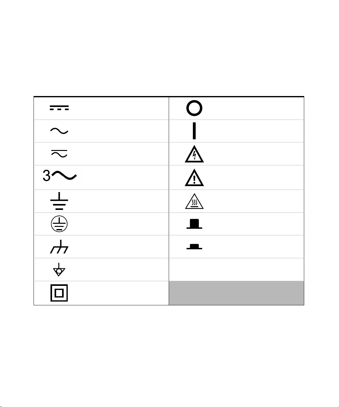
The following symbols on the instrument and in the documentation indicate
precautions which must be taken to maintain safe operation of the instrument.
Direct current (DC) Off (mains supply)
Alternating current (AC) On (mains supply)
Both direct and alternating current Caution, risk of electric shock
Three-phase alternating current
Earth (ground) terminal Caution, hot surface
Protective earth (ground) terminal Out position of a bi-stable push control
Caution, risk of danger (refer to this
manual for specific Warning or Caution
information)
Frame or chassis (ground) terminal In position of a bi-stable push control
Equipotentiality
Equipment protected throughout by
double insulation or reinforced
insulation
Category II 300 V overvoltage
protection
Keysight U2741A User’s Guide 3
Page 4

General Safety Information
WARNING
CAUTION
– Do not use the device if it is damaged. Before you use the device, inspect
the casing. Look for cracks or missing plastic. Do not operate the device
around explosive gas, vapor, or dust.
– Always use the device with the cables provided.
– Observe all markings on the device before establishing any connection.
– Turn off the device and application system power before connecting to
the I/O terminals.
– When servicing the device, use only the specified replacement parts.
– Do not operate the device with the cover removed or loosened.
– Use only the power adapter provided by the manufacturer to avoid any
unexpected hazards.
– If the device is used in a manner not specified by the manufacturer, the
device protection may be impaired.
– Always use dry cloth to clean the device. Do not use ethyl alcohol or any
other volatile liquid to clean the device.
– Do not permit any blockage of the ventilation holes of the device.
4 Keysight U2741A User’s Guide
Page 5

Environmental Conditions
CAUTION
This instrument is designed for indoor use and in an area with low condensation.
The table below shows the general environmental requirements for this instrument.
Environmental condition Requirement
Operating temperature 0 °C to 50 °C
Operating humidity 20% to 85% RH non-condensing
Storage temperature –20 °C to 70 °C
Storage humidity 5% to 90% RH non-condensing
The U2741A USB modular digital multimeter complies with the following
safety and EMC requirements.
– IEC 61010-1:2001/EN61010-1:2001 (2nd Edition)
– Canada: CAN/CSA-C22.2 No. 61010-1-04
– USA: ANSI/UL 61010-1:2004
– IEC 61326-2002/EN 61326:1997+A1:1998+A2:2001+A3:2003
– Canada: ICES-001:2004
– Australia/New Zealand: AS/NZS CISPR11:2004
Keysight U2741A User’s Guide 5
Page 6
Regulatory Markings
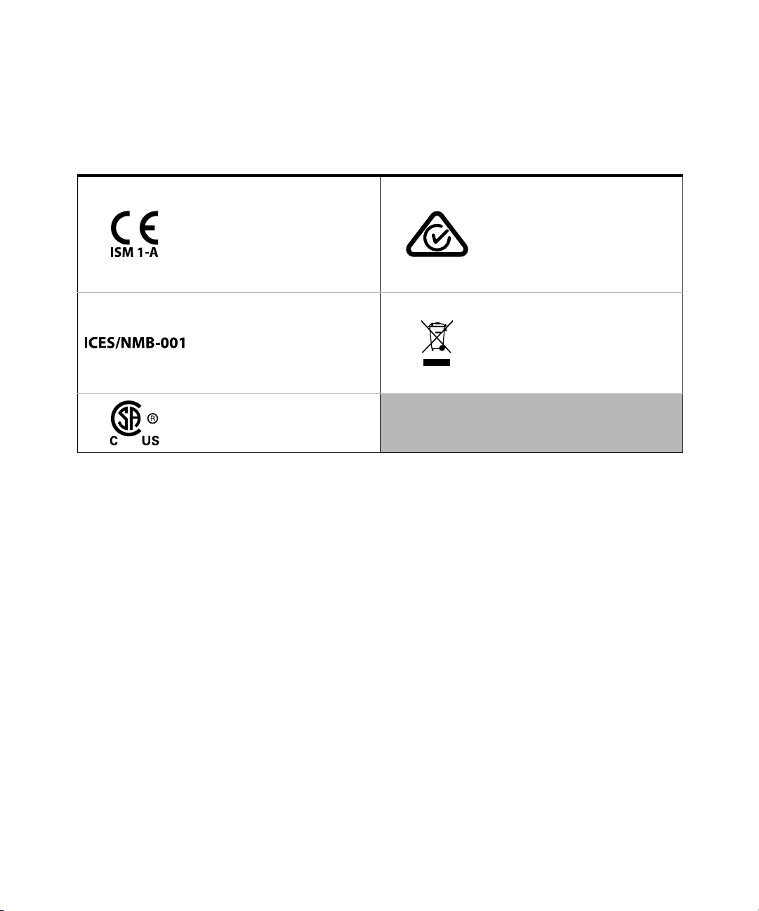
The CE mark is a registered trademark
of the European Community. This CE
mark shows that the product complies
with all the relevant European Legal
Directives.
ICES/NMB-001 indicates that this ISM
device complies with the
Canadian ICES-001.
Cet appareil ISM est conforme a la
norme NMB-001 du Canada.
The CSA mark is a registered
trademark of the Canadian
Standards Association.
The RCM mark is a registered
trademark of the Spectrum
Management Agency of Australia.
This signifies compliance with the
Australia EMC Framework regulations
under the terms of the Radio
Communication Act of 1992.
This instrument complies with the
WEEE Directive (2002/96/EC) marking
requirement. This affixed product label
indicates that you must not discard
this electrical or electronic product in
domestic household waste.
6 Keysight U2741A User’s Guide
Page 7
Waste Electrical and Electronic Equipment (WEEE) Directive 2002/96/EC
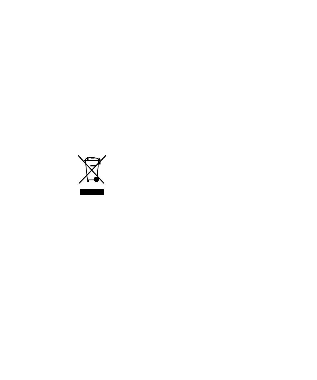
This instrument complies with the WEEE Directive (2002/96/EC) marking
requirement. This affixed product label indicates that you must not discard this
electrical or electronic product in domestic household waste.
Product category:
With reference to the equipment types in the WEEE directive Annex 1, this
instrument is classified as a “Monitoring and Control Instrument” product.
The affixed product label is as shown below.
Do not dispose in domestic household waste.
Keysight U2741A User’s Guide 7
Page 8

THIS PAGE HAS BEEN INTENTIONALLY LEFT BLANK.
8 Keysight U2741A User’s Guide
Page 9

Table of Contents
Safety Symbols . . . . . . . . . . . . . . . . . . . . . . . . . . . . . . . . . . . . . . . . . . . . .3
General Safety Information . . . . . . . . . . . . . . . . . . . . . . . . . . . . . . . . . . . .4
Environmental Conditions . . . . . . . . . . . . . . . . . . . . . . . . . . . . . . . . . . . .5
Regulatory Markings . . . . . . . . . . . . . . . . . . . . . . . . . . . . . . . . . . . . . . . . .6
Waste Electrical and Electronic Equipment (WEEE) Directive
2002/96/EC . . . . . . . . . . . . . . . . . . . . . . . . . . . . . . . . . . . . . . . . . . . . .7
Product category: . . . . . . . . . . . . . . . . . . . . . . . . . . . . . . . . . . . . . . . .7
Sales and Technical Support . . . . . . . . . . . . . . . . . . . . . . . . . . . . . . . . . .7
1 Getting Started
Introduction . . . . . . . . . . . . . . . . . . . . . . . . . . . . . . . . . . . . . . . . . . . . . .16
Product at a Glance . . . . . . . . . . . . . . . . . . . . . . . . . . . . . . . . . . . . . . . .17
Product outlook . . . . . . . . . . . . . . . . . . . . . . . . . . . . . . . . . . . . . . . . .17
Product Dimensions . . . . . . . . . . . . . . . . . . . . . . . . . . . . . . . . . . . . . . . .19
Dimensions without bumpers . . . . . . . . . . . . . . . . . . . . . . . . . . . . . .19
Dimensions with bumpers . . . . . . . . . . . . . . . . . . . . . . . . . . . . . . . . .20
Standard Shipped Items . . . . . . . . . . . . . . . . . . . . . . . . . . . . . . . . . . . . .21
Inspection and Maintenance . . . . . . . . . . . . . . . . . . . . . . . . . . . . . . . . .22
Initial inspection . . . . . . . . . . . . . . . . . . . . . . . . . . . . . . . . . . . . . . . . .22
Electrical check . . . . . . . . . . . . . . . . . . . . . . . . . . . . . . . . . . . . . . . . .22
General maintenance . . . . . . . . . . . . . . . . . . . . . . . . . . . . . . . . . . . . .23
Installation and Configuration . . . . . . . . . . . . . . . . . . . . . . . . . . . . . . . .24
Instrument Configuration . . . . . . . . . . . . . . . . . . . . . . . . . . . . . . . . . . . .25
55-Pin backplane connector pin configuration . . . . . . . . . . . . . . . . .25
Chassis installation . . . . . . . . . . . . . . . . . . . . . . . . . . . . . . . . . . . . . .26
2Operation and Features
Powering Up . . . . . . . . . . . . . . . . . . . . . . . . . . . . . . . . . . . . . . . . . . . . . .28
Making Measurements . . . . . . . . . . . . . . . . . . . . . . . . . . . . . . . . . . . . . .29
Measuring DC voltage . . . . . . . . . . . . . . . . . . . . . . . . . . . . . . . . . . . .29
Keysight U2741A User’s Guide 9
Page 10

Measuring AC voltage . . . . . . . . . . . . . . . . . . . . . . . . . . . . . . . . . . . . 31
Measuring DC current . . . . . . . . . . . . . . . . . . . . . . . . . . . . . . . . . . . . 32
Measuring AC current . . . . . . . . . . . . . . . . . . . . . . . . . . . . . . . . . . . . 33
Measuring resistance . . . . . . . . . . . . . . . . . . . . . . . . . . . . . . . . . . . . 34
Measuring frequency . . . . . . . . . . . . . . . . . . . . . . . . . . . . . . . . . . . . . 36
Testing continuity . . . . . . . . . . . . . . . . . . . . . . . . . . . . . . . . . . . . . . . 37
Testing diodes . . . . . . . . . . . . . . . . . . . . . . . . . . . . . . . . . . . . . . . . . . 38
Measuring temperature . . . . . . . . . . . . . . . . . . . . . . . . . . . . . . . . . . . 39
Restoring Instrument State . . . . . . . . . . . . . . . . . . . . . . . . . . . . . . . . . . 40
Autozero . . . . . . . . . . . . . . . . . . . . . . . . . . . . . . . . . . . . . . . . . . . . . . 40
Ranging . . . . . . . . . . . . . . . . . . . . . . . . . . . . . . . . . . . . . . . . . . . . . . . 41
Default Settings . . . . . . . . . . . . . . . . . . . . . . . . . . . . . . . . . . . . . . . . . . . 42
Triggering the U2741A . . . . . . . . . . . . . . . . . . . . . . . . . . . . . . . . . . . . . . 43
System-Related Operation . . . . . . . . . . . . . . . . . . . . . . . . . . . . . . . . . . 45
Error conditions . . . . . . . . . . . . . . . . . . . . . . . . . . . . . . . . . . . . . . . . . 45
3Measurement Tutorial
DC Measurement Considerations . . . . . . . . . . . . . . . . . . . . . . . . . . . . . 48
Noise Rejection . . . . . . . . . . . . . . . . . . . . . . . . . . . . . . . . . . . . . . . . . . . 49
Resistance Measurement Considerations . . . . . . . . . . . . . . . . . . . . . . . 52
AC Measurements . . . . . . . . . . . . . . . . . . . . . . . . . . . . . . . . . . . . . . . . . 55
Other Primary Measurement Functions . . . . . . . . . . . . . . . . . . . . . . . . . 57
Frequency measurement errors . . . . . . . . . . . . . . . . . . . . . . . . . . . . 57
DC current measurements . . . . . . . . . . . . . . . . . . . . . . . . . . . . . . . . 57
Other Sources of Measurement Error . . . . . . . . . . . . . . . . . . . . . . . . . . 59
4Characteristics and Specifications
10 Keysight U2741A User’s Guide
Page 11

List of Figures
Figure 1-1 55-pin backplane connector pin configuration . . . . . .25
Figure 3-1 Common mode source error . . . . . . . . . . . . . . . . . . . .49
Figure 3-2 Ground loop induced error . . . . . . . . . . . . . . . . . . . . . .51
Figure 3-3 Burden voltage in current measurement . . . . . . . . . . .58
Keysight U2741A User’s Guide 11
Page 12

THIS PAGE HAS BEEN INTENTIONALLY LEFT BLANK.
12 Keysight U2741A User’s Guide
Page 13

List of Tables
Table 1-1 SSI connector pin description . . . . . . . . . . . . . . . . . . .25
Table 2-1 Default settings summary . . . . . . . . . . . . . . . . . . . . . .42
Table 3-1 Thermoelectric voltage for dissimilar metals
connections . . . . . . . . . . . . . . . . . . . . . . . . . . . . . . .48
Table 3-2 Power dissipation for various resistance ranges . . . . .54
Table 3-3 Waveform shapes and their parameters . . . . . . . . . . .55
Keysight U2741A User’s Guide 13
Page 14

THIS PAGE HAS BEEN INTENTIONALLY LEFT BLANK.
14 Keysight U2741A User’s Guide
Page 15

Keysight U2741A USB Modular 5.5 Digits Digital Multimeter
User’s Guide
1 Getting Started
Introduction 16
Product at a Glance 17
Product Dimensions 19
Standard Shipped Items 21
Inspection and Maintenance 22
Installation and Configuration 24
Instrument Configuration 25
15
Page 16

1 Getting Started
Introduction
The Keysight U2741A is a 5.5 digits digital multimeter that can operate as
standalone or as a modular unit when used with the U2781A USB modular
instrument chassis.
U2741A can perform the following measurements:
–DC Voltage
–AC Voltage
– DC Current
– AC Current
– Resistance
–Diode Test
– Continuity Test
–Temperature
– Frequency
The U2741A is controlled remotely over a USB interface via the Keysight
Measurement Manager (KMM) software. The U2741A can also be programmed
using the provided drivers or via SCPI commands in your customized application.
16 Keysight U2741A User’s Guide
Page 17
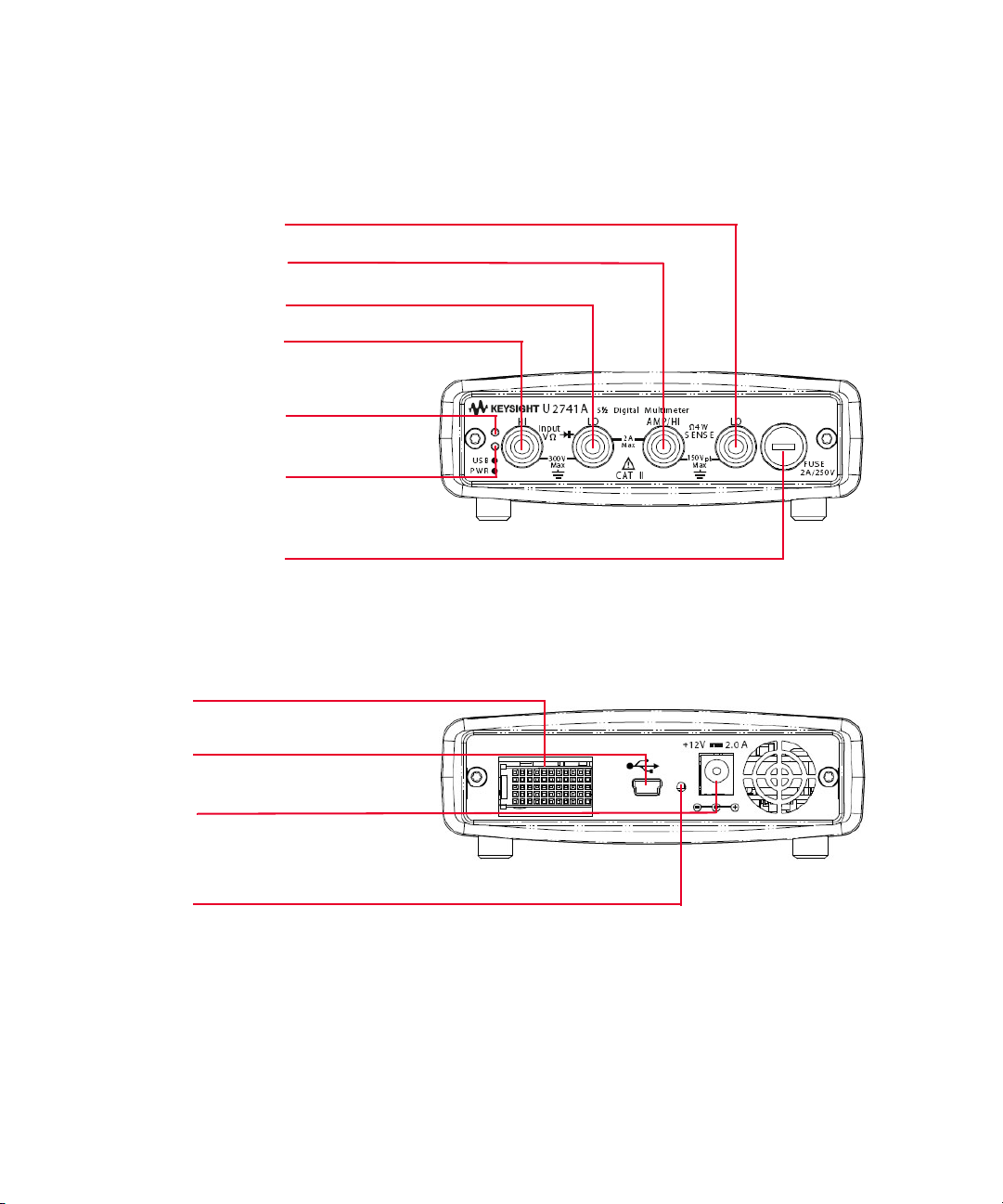
Product at a Glance
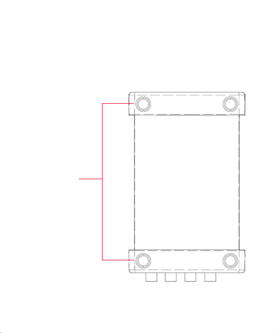
Bumpers
Product outlook
Top view
Getting Started 1
Keysight U2741A User’s Guide 17
Page 18
1 Getting Started
USB Indicator
Power Indicator
Fuse holder
4-wire Ω Lo Sense
4-wire Ω Hi Sense
VOLT HI
VOLT LO
55-pin backplane connector
USB inlet
Power inlet
Fastening hole for USB cable with locking mechanism
Front view
18 Keysight U2741A User’s Guide
Rear view
Page 19
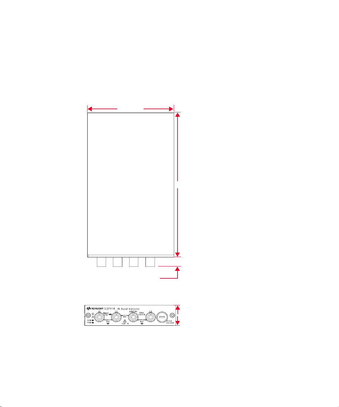
Product Dimensions
105.00 mm
175.00 mm
11.50 mm
25.00 mm
Dimensions without bumpers
Top view
Getting Started 1
Front view
Keysight U2741A User’s Guide 19
Page 20
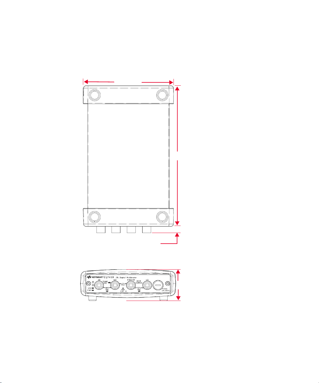
1 Getting Started
180.00 mm
8.60 mm
117.00 mm
41.00 mm
Dimensions with bumpers
Top view
Front view
20 Keysight U2741A User’s Guide
Page 21

Standard Shipped Items
Verify that you have received the following items with your unit. If anything is
missing or damaged, please contact the nearest Keysight Sales Office.
✔ 12 V, 2 A AC/DC adapter
✔ Power cord
✔ Standard Test Lead
✔ USB Standard-A to Mini-B interface cable
✔ L-Mount kit (used with the modular instrument chassis)
✔ Keysight Automation-Ready CD-ROM (contains the Keysight IO Libraries
Suite)
✔ Keysight USB Modular Products and Systems Quick Start Guide
✔ Keysight USB Modular Products and Systems Product Reference DVD-ROM
✔ Keysight Measurement Manager Quick Reference Card
✔ Certificate of Calibration
Getting Started 1
Keysight U2741A User’s Guide 21
Page 22

1 Getting Started
Inspection and Maintenance
Initial inspection
When you receive your U2741A, inspect the unit for any obvious damage such as
broken terminals or cracks, dents, and scratches on the casing that may occur
during shipment.
If any damage is found, notify the nearest Keysight Sales Office immediately. The
front of this manual contains the warranty information.
Keep the original packaging in case the U2741A has to be returned to Keysight in
the future. If you return the U2741A for service, attach a tag identifying the owner
and model number. Also include a brief description of the problem.
Electrical check
For verification procedures, refer to Keysight U2741A USB Modular 5.5 Digits
Digital Multimeter Service Guide. The procedures will verify to a high level of
confidence that the U2741A is operating in accordance to its specifications.
22 Keysight U2741A User’s Guide
Page 23

General maintenance
NOTE
General maintenance
Any repair that is not covered in your modular product manuals should only be
performed by qualified personnel.
1 Power off your module and remove the power cord and I/O cable from your
device.
2 Remove your module from the bumper casing.
3 Shake out any dirt that may have accumulated on the module.
4 Wipe your module with a dry cloth and install the bumper back in place.
Getting Started 1
Keysight U2741A User’s Guide 23
Page 24

1 Getting Started
NOTE
Installation and Configuration
Follow the step-by-step instructions shown in the Keysight USB Modular
Products and Systems Quick Start Guide to get started with the preparations and
installations of your U2741A.
You need to install the IVI-COM driver if you are going to use the U2741A with
Keysight VEE Pro, LabVIEW, or Microsoft
®
Visual Studio®.
24 Keysight U2741A User’s Guide
Page 25
Instrument Configuration
GND
NC
GND
TRIG4
nBPUB
NC
11
GND
NC
TRIG3
GND
CLK10M
NC
10
GND
NC
GND
TRIG5
GND
NC
9
GND
NC
STAR_TRIG
NC
8
TRIG2
GND
GND
NC
ND
TRIG6
GA2
NC
7
GND
NC
TRIG1
GND
GA1
NC
6
GND
NC
GND
TRIG7
GA0
NC
5
GND
NC
TRIG0
GND
NC
NC
4
GND
VBUS
GND
+12 V
+12 V
+12 V
3
GND
GND
GND
+12 V
+12 V
+12 V
2
GND
USB_D–
USB_D+
GND
+12 V
+12 V
1
F
E
D
C
B
A
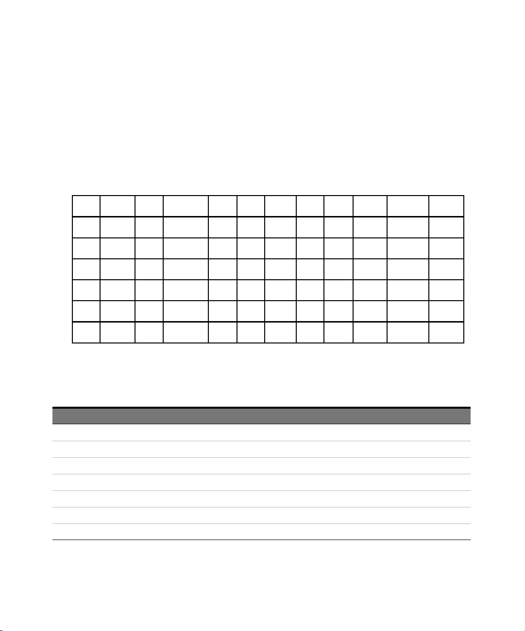
55-Pin backplane connector pin configuration
The 55-pin backplane connector is used when the U2741A module is inserted into
the U2781A USB modular instrument chassis. For more details, refer to the
Keysight U2781A USB Modular Instrument Chassis User's Guide.
Getting Started 1
Figure 1-1 55-pin backplane connector pin configuration
Table 1-1 SSI connector pin description
SSI timing signal Functionality
GND Ground
NC Not connected
VBUS USB bus power sensing input
USB_D+, USB_D– USB differential pair
TRIG0~TRIG7 Trigger bus
+12 V +12 V power with 4 A current
nBPUB USB backplane input detect
Keysight U2741A User’s Guide 25
Page 26

1 Getting Started
Tab le 1-1 SSI connector pin description (continued)
SSI timing signal Functional ity
CLK10M 10 MHz clock source
STAR_TRIG Star trigger
GA0,GA1,GA2 Geographical address pin
Chassis installation
The L-Mount kit is to be installed to your U2741A module.
The following instructions describe the simple procedure of installing the L-Mount
kit and your module in the chassis.
1 Unpack the L-Mount kit from the packaging.
2 Remove your U2741A module from the bumper casing.
3 Use a Phillips screwdriver to fasten the L-Mount kit to your U2741A module.
4 Insert your U2741A module into the U2781A chassis with the 55-pin
backplane connector positioned at the bottom of the module.
5 Once you have slotted in the module, tighten the screws of the L-Mount kit to
secure the connection.
26 Keysight U2741A User’s Guide
Page 27

Keysight U2741A USB Modular 5.5 Digits Digital Multimeter
User’s Guide
2 Operation and Features
Powering Up 28
Making Measurements 29
Restoring Instrument State 40
Default Settings 42
Triggering the U2741A 43
System-Related Operation 45
This chapter contains the details on how to configure your U2741A USB modular
digital multimeter to perform the various measurement functions either through
the software front panel or by sending SCPI commands remotely via the USB
interface.
27
Page 28

2 Operation and Features
Powering Up
Take note of the following when you power up the U2741A.
– The U2741A can only be operated via the USB interface.
– Before you can control the U2741A, you need to install the hardware driver
and the IO Libraries Suite 14.2 or higher. Both of these are included when you
purchase the U2741A. Refer to the Keysight USB Modular Products and
Systems Quick Start Guide for the installation procedure.
– On the front panel of the U2741A, there are two LED indicators. Refer to
Chapter 1, “Product outlook” on page 17.
– Power indicator lights up once the U2741A is powered up. It will blink if there
is a system error.
– USB indicator will only blink when there is data exchange activity between the
U2741A and the PC.
You can control your U2741A via the KMM for U2741A or via SCPI commands sent
through the USB interface from your own application programs.
The Keysight U2741A complies with the syntax rules and conventions of SCPI
commands.
You can determine the U2741A's SCPI language version by sending the
SYSTem:VERSion? command from the remote interface.
For a complete discussion of U2741A's SCPI syntax, refer to the Keysight U2741A
Programmer's Reference.
28 Keysight U2741A User’s Guide
Page 29
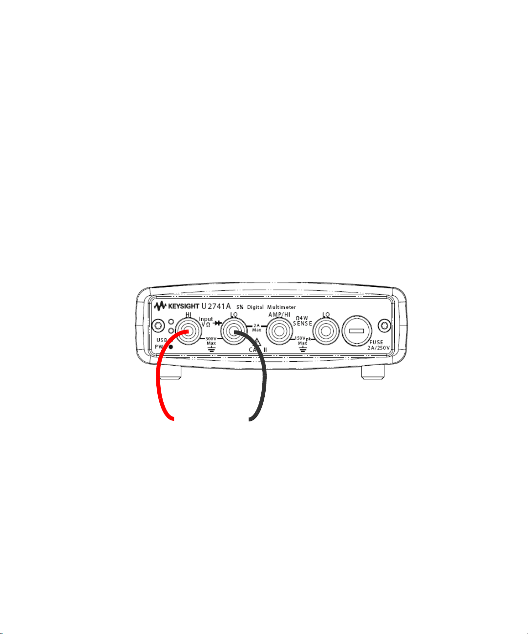
Making Measurements
DC Voltage Source
+–
The following pages show how to make measurement connections and how to
select measurement functions from the front panel for each of the measurement
functions.
Measuring DC voltage
The DC voltage measurement function has the following features:
– Five ranges to select: 100 mV, 1 V, 10 V, 100 V, and 300 V, or auto-range.
– Input impedance is 10 MΩ for all ranges (typical).
– Input protection is 300 V on all ranges (HI terminal).
Make the connection as shown below.
Operation and Features 2
Keysight U2741A User’s Guide 29
Page 30

2 Operation and Features
Keysight Measurement Manager operation
Select the DCV function and desired range. A suitable range should be selected to
give the best measurement resolution. The reading is displayed and updated
continuously.
SCPI commands
The following example shows how to make a DC voltage measurement using SCPI
commands.
MEASure[:VOLTage]:DC?
30 Keysight U2741A User’s Guide
Page 31
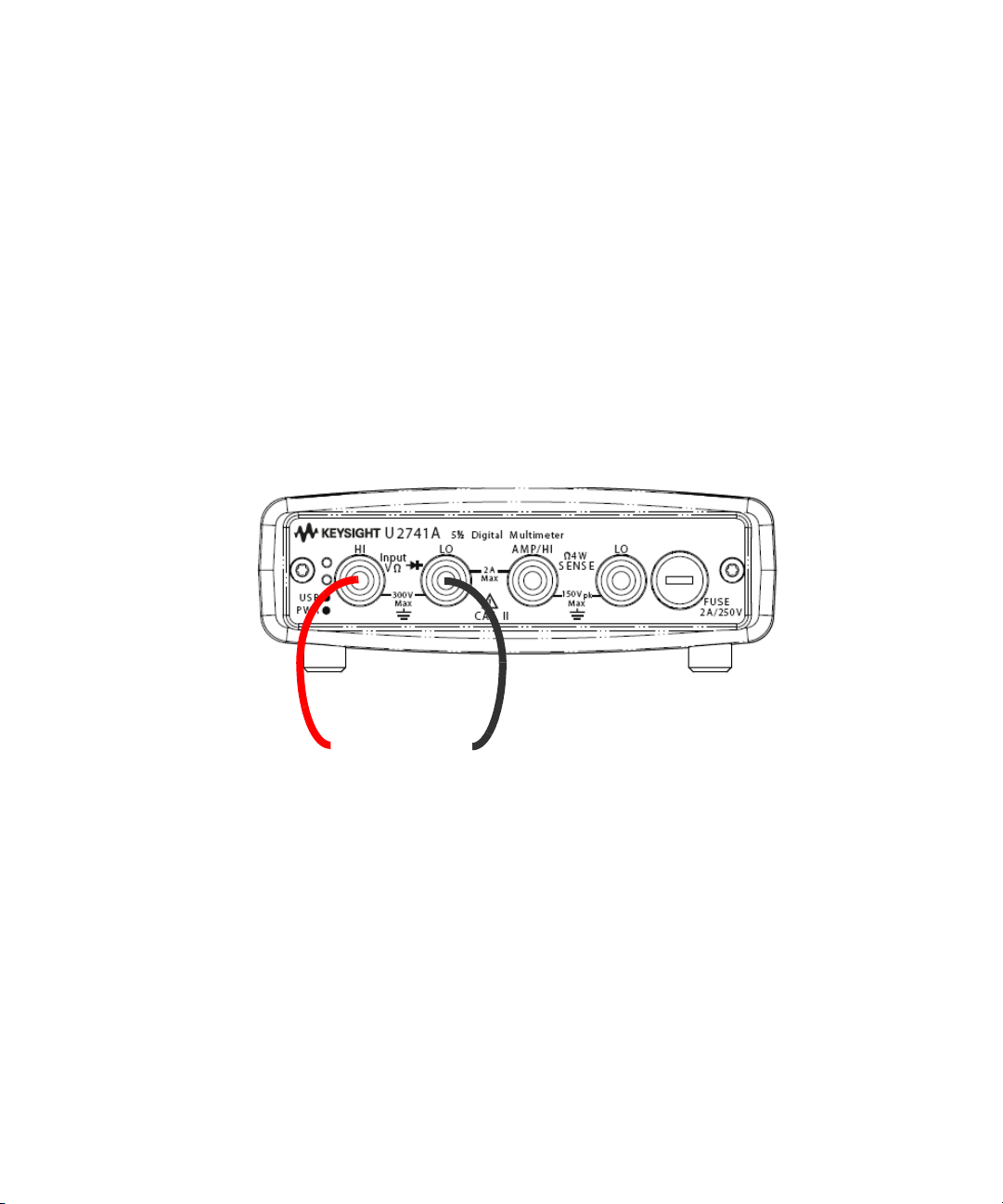
Measuring AC voltage
AC Voltage Source
+–
The AC voltage measurement function has the following features:
– Five ranges to select: 100 mVrms, 1 Vrms, 10 Vrms, 100 Vrms, and 250 Vrms,
or auto-range.
– Measures the AC-coupled true RMS.
– Measures within the stipulated accuracy at a crest factor of a maximum of 5:1
(full scale).
– Input impedance is 1 MΩ ± 2% in parallel with less than 120 pF capacitance on
all ranges.
Make the connection as shown below.
Operation and Features 2
Keysight Measurement Manager operation
Select the ACV function and desired range. A suitable range should be selected to
give the best measurement resolution. The reading is displayed and updated
continuously.
SCPI commands
The following example shows how to make an AC voltage measurement using
SCPI commands.
MEASure[:VOLTage]:AC?
Keysight U2741A User’s Guide 31
Page 32
2 Operation and Features
DC Current Source
+
–
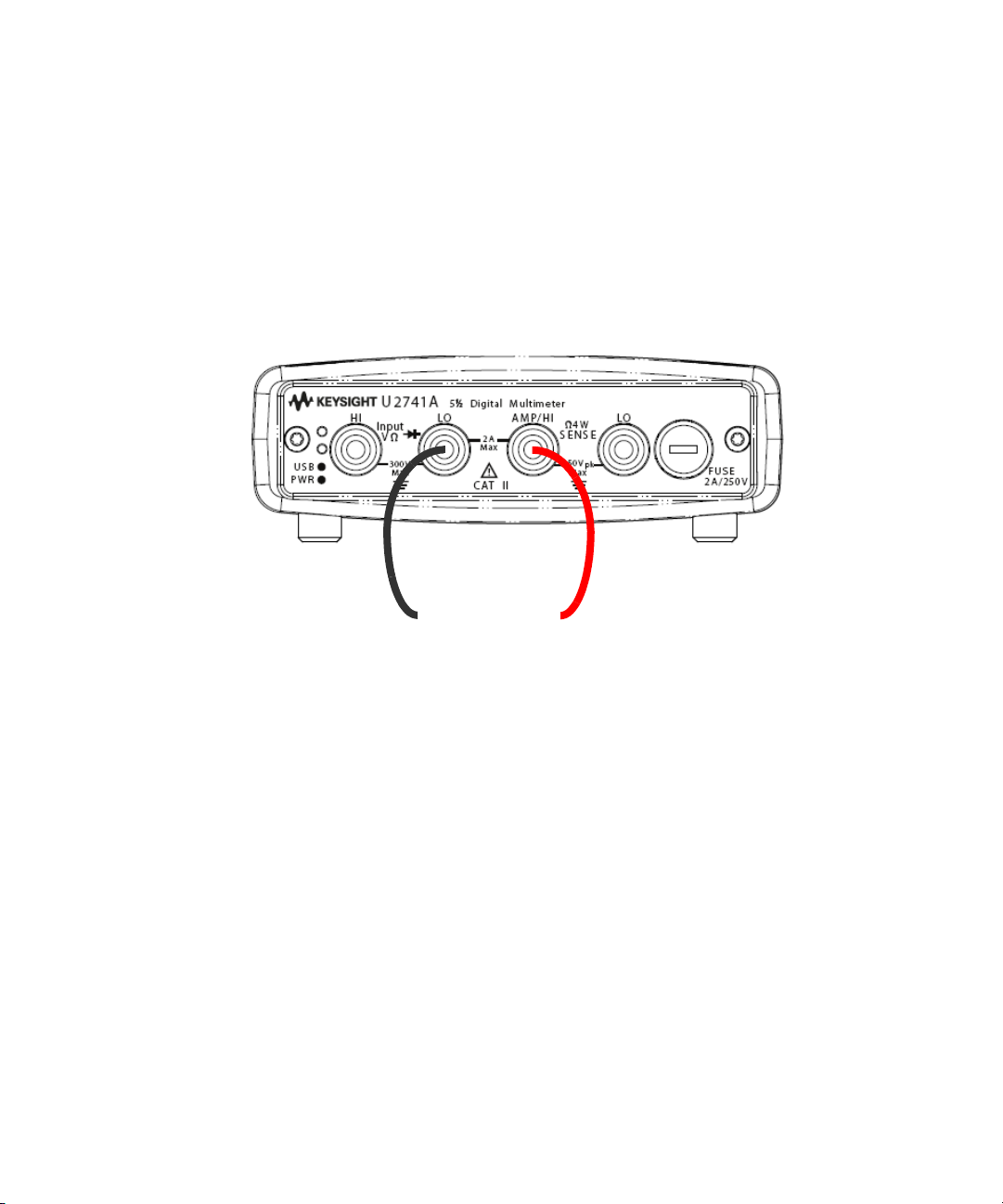
Measuring DC current
The DC current measurement function has the following features:
– Three ranges to select: 10 mA, 100 mA, 1 A and 2 A, or auto-range.
– Input protection fuse is 2 A, voltage rating 250 V on all ranges.
Make the connection as shown below.
Keysight Measurement Manager operation
Select the DCI function and desired range. A suitable range should be selected to
give the best measurement resolution. The reading is displayed and updated
continuously.
SCPI commands
The following example shows how to make a DC current measurement using SCPI
commands.
MEASure:CURRent[:DC]?
32 Keysight U2741A User’s Guide
Page 33
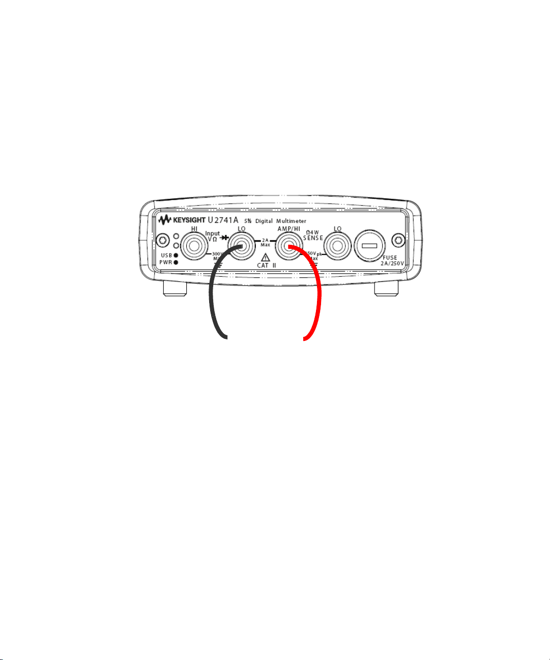
Measuring AC current
AC Current Source
+
–
The AC current measurement function has the following features:
– Three ranges to select: 10 mA, 100 mA, 1 A and 2 A or, auto-range.
– Measures true rms value.
Make the connection as shown below.
Operation and Features 2
Keysight Measurement Manager operation
Select the ACI function and desired range. A suitable range should be selected to
give the best measurement resolution. The reading is displayed and updated
continuously.
SCPI commands
The following example shows how to make an AC current measurement using
SCPI commands.
MEASure:CURRent:AC?
Keysight U2741A User’s Guide 33
Page 34
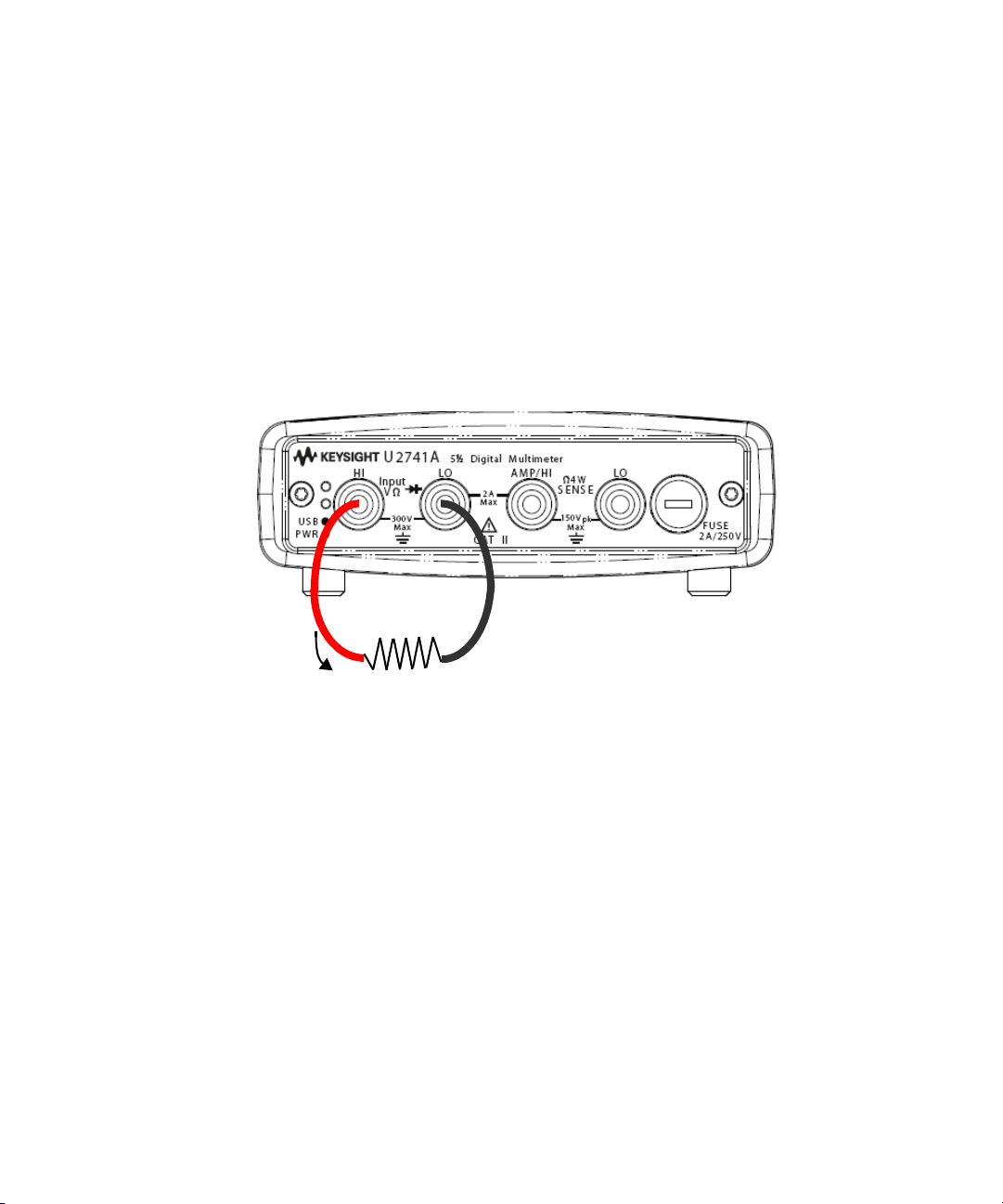
2 Operation and Features
Resistance
Test
Current
Measuring resistance
The resistance measurement function has the following features:
– Seven ranges to select: 100 Ω, 1 kΩ, 10 kΩ, 100 kΩ, 1 MΩ, 10 MΩ, and
100 MΩ or, auto-range.
– Supports two-wire and four-wire resistance measurement.
– Open circuit voltage is limited to less than 4.5 V on all ranges.
The figure below shows a two-wire resistance measurement connection.
34 Keysight U2741A User’s Guide
Page 35
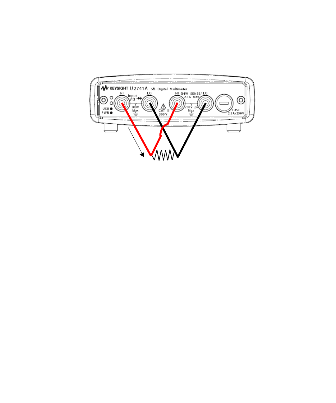
Operation and Features 2
Test Current
The following figure shows a four-wire resistance measurement connection.
Keysight Measurement Manager operation
Select the 2-Wired Ω function and desired range for two-wire resistance
measurement. Select the 4-Wired Ω function and desired range for four-wire
resistance measurement. A suitable range should be selected to give the best
measurement resolution. The reading is displayed and updated continuously.
SCPI commands
The following example shows how to make a resistance measurement using SCPI
commands.
Two-wire: MEASure:RESistance?
Four-wire: MEASure:FRESistance?
Keysight U2741A User’s Guide 35
Page 36
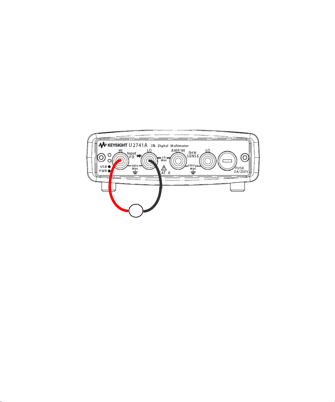
2 Operation and Features
Frequency Source
~
Measuring frequency
The frequency measurement function has the following features:
– Range is based on the amplitude of the signal.
– Employs a reciprocal counting technique as the measurement method.
– Gate time can be set at 0.1 second or 1 second of the input signal.
Make the connection as shown below.
Keysight Measurement Manager operation
Select the Freq function and desired range. The reading is displayed and updated
continuously.
SCPI commands
The following example shows how to make a frequency measurement using SCPI
commands.
MEASure:FREQuency?
36 Keysight U2741A User’s Guide
Page 37
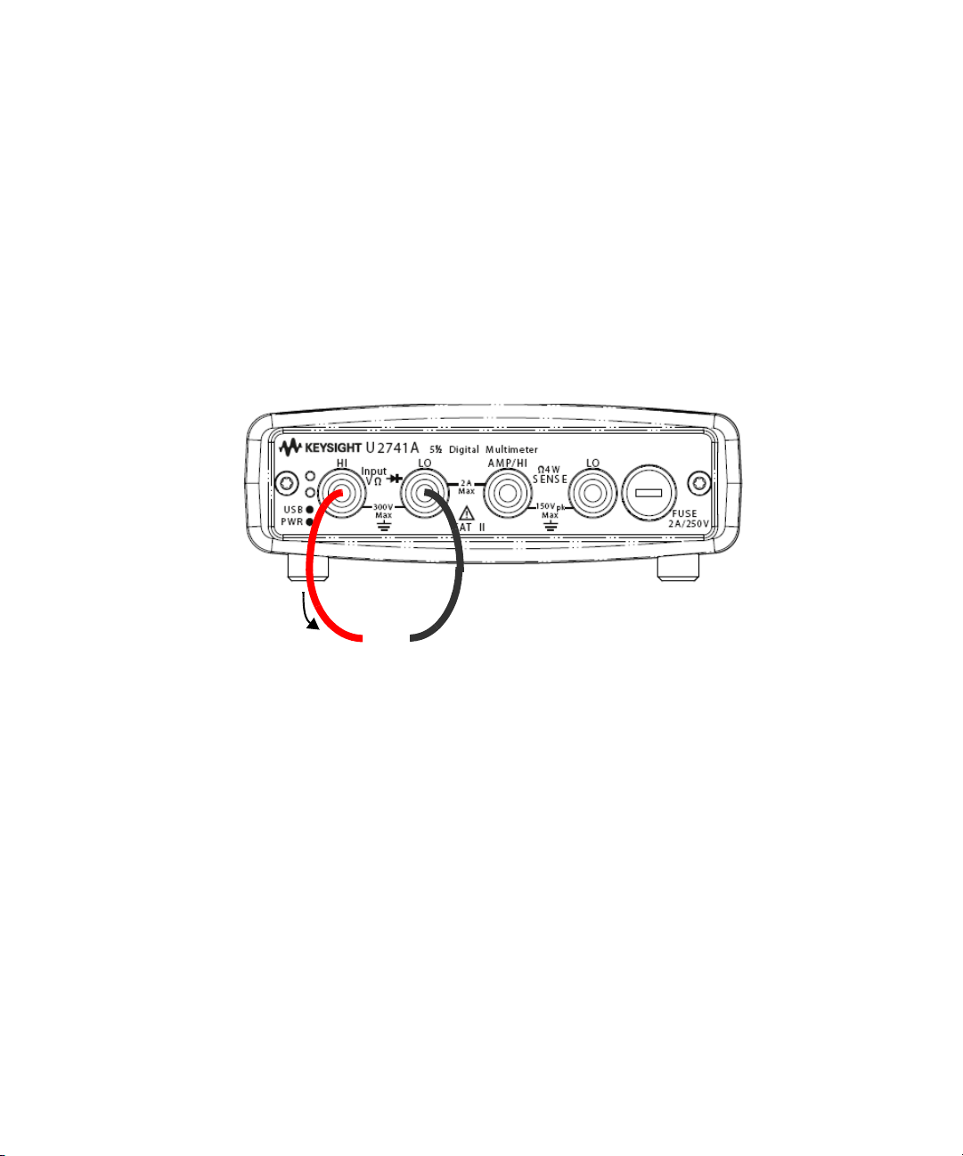
Testing continuity
Open or closed circuit
Current
Test
The continuity testing function has the following features:
– Uses a 1 mA ± 0.2% constant current source.
– Open circuit voltage is limited to less than 4.5 V for all ranges.
– Continuity threshold is fixed at 10 Ω.
– Response time is 60 samples/second.
Make the connection as shown below.
Operation and Features 2
Keysight Measurement Manager operation
)
Select the Cont-
)
) function. The reading is displayed and updated continuously.
SCPI commands
The following example shows how to make a Continuity Test measurement using
SCPI commands.
MEASure:CONTinuity?
Keysight U2741A User’s Guide 37
Page 38
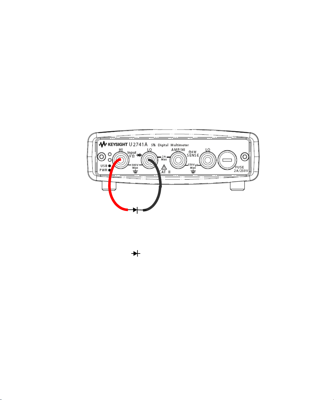
2 Operation and Features
Forward bias
Testing diodes
The diode testing function has the following features:
– Uses a 1 mA ± 0.2% constant current source.
– Open circuit voltage is limited to less than 4.5 V for all ranges.
– Response time is 60 samples/second.
Make the connection as shown below.
Keysight Measurement Manager operation
Select the Diode function. The reading is displayed and updated
continuously.
SCPI commands
The following example shows how to make a Diode Test measurement using SCPI
commands.
MEASure:DIODe?
38 Keysight U2741A User’s Guide
Page 39
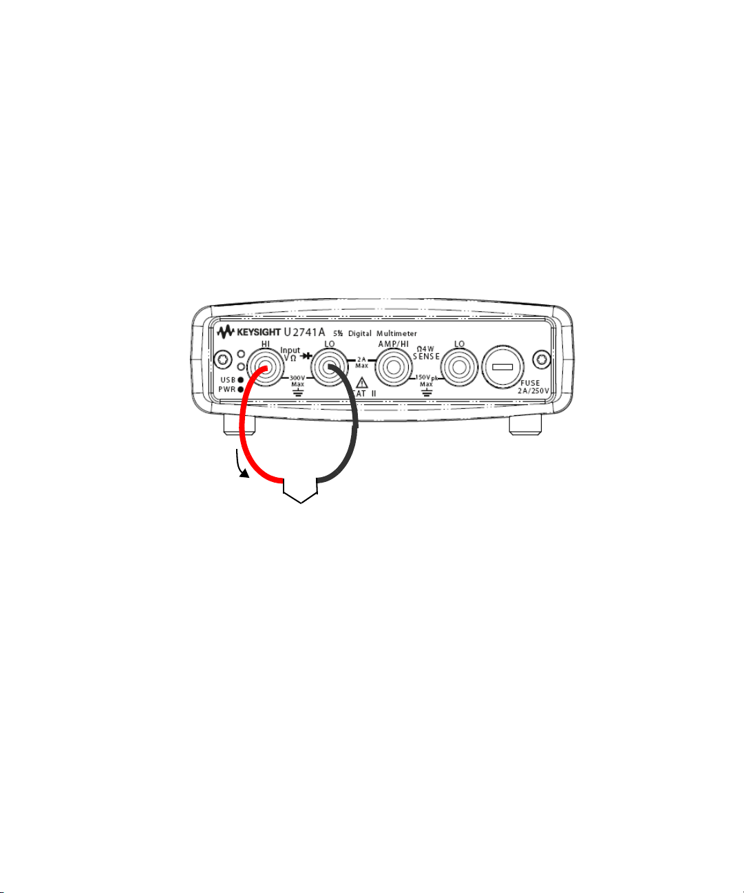
Measuring temperature
Thermistor
The temperature measurement function has the following features:
– The measurement range is dependant on the type of temperature sensor used.
For the specification details of the temperature sensors, please refer to
Chapter 4, “Characteristics and Specifications”.
– Measurements are in auto-range for 5 kΩ thermistor probe.
– Supports the thermistor.
Make the connection as shown below.
Operation and Features 2
Keysight Measurement Manager operation
Select the Temp function and the type of thermistor used. The reading is
displayed and updated continuously.
SCPI commands
The following example shows how to make a temperature measurement using
SCPI commands.
MEASure:TEMPerature? THER //Used for thermistor measurement
Keysight U2741A User’s Guide 39
Page 40

2 Operation and Features
Restoring Instrument State
The U2741A automatically saves the last configuration whenever a power-down
event occurs and restores to the last power-down state when you turn on the
instrument.
Autozero
When autozero is enabled, the digital multimeter internally disconnects the input
signal following each measurement, and takes a zero reading. It then subtracts
the zero reading from the preceding reading. This prevents offset voltages present
on the digital multimeter’s input circuitry from affecting measurement accuracy.
This is applicable to DC voltage, DC current, two-wire ohms and temperature
measurements only.
SCPI Commands
The following commands are used to set the autozero:
VOLTage:ZERO:AUTO {OFF|ON}
CURRent:ZERO:AUTO {OFF|ON}
RESistance:ZERO:AUTO {OFF|ON}
TEMPerature:ZERO:AUTO {OFF|ON}
40 Keysight U2741A User’s Guide
Page 41

Ranging
Operation and Features 2
You can let the digital multimeter automatically select the range using auto range
or you can select a fixed range using manual range. Autoranging is convenient
because the digital multimeter automatically selects the appropriate range for
each measurement. However, you can use manual range for faster measurements
since the digital multimeter does not have to determine which range to use for
each measurement.
– Autorange thresholds:
Down range at: <10% of range
Up range at: >120% of range
– For manual range, if the input signal is greater than the present range can
measure, the digital multimeter gives an overload indication: “9.9E+37” from
the remote interface. For auto range, the digital multimeter will give an
overload indication “9.9E+37” if the input signal is greater than the highest
measurement range.
– The range is fixed for continuity tests (1 kΩ range) and diode tests (1 VDC
range with 1 mA current source output).
SCPI Commands
You can set the range using any of the following commands.
CONFigure:<function> {<range>|MIN|MAX|AUTO},
{<resolution>|MIN|MAX|DEF}
MEASure:<function>? {<range>|MIN|MAX|AUTO},
{<resolution>|MIN|MAX|DEF}
<function>:RANGe {<range>|MINimum|MAXimum|AUTO}
<function>:RANGe:AUTO {OFF|ON}
Keysight U2741A User’s Guide 41
Page 42

2 Operation and Features
Default Settings
The table below summarizes the U2741A's settings as received from the factory,
at power-on or following the *RST command received over the USB remote
interface.
Tab le 2-1 Default settings summary
Parameter Factory Setting Power-on/Reset State
Measurement Configuration
Function DCV DCV
Range AUTO AUTO
Resolution
Temperature Unit °C User setting
Trigger Operation
Trigger Source Auto Trigger Auto Trigger
System-Related Operation
Power-Down Recall Disabled User Setting
Stored States 0-10 Cleared No Change
Reading Output Buffer Cleared Cleared
Error Queue Cleared Cleared
Power-on Status Clear Enabled User Setting
Status Registers, Masks & Transition Filter Cleared Cleared in power-on status clear
Calibration
Calibration State Secured User Setting
Calibration Value 0 No Change
Calibration String Cleared No Change
5.5 digits 5.5 digits
enabled
42 Keysight U2741A User’s Guide
Page 43

Triggering the U2741A
At power-up, the default trigger source is immediate. To make a measurement,
the following steps are to be followed:
– Configure the U2741A by selecting the function, range, resolution, and so on.
– Specify the digital multimeter's trigger source. You can select software bus
trigger or an immediate internal trigger (default trigger source).
– Ensure that the U2741A is in wait-for-trigger state to accept a trigger from the
specified source.
Immediate triggering
In the immediate trigger mode, the trigger signal is always present. When you
place the U2741A in the wait-for-trigger state, the trigger is issued immediately.
This is the default trigger source.
SCPI command
The following command sets the trigger source to immediate:
TRIGger:SOURce IMMediate
Operation and Features 2
Software bus triggering
The bus trigger mode is initiated by sending a bus trigger command, after
selecting BUS as the trigger source.
SCPI command
The following command sets the trigger source to bus:
TRIGger:SOURce BUS
The MEASure? and READ? command overwrites the BUS trigger and triggers the
digital multimeter and returns a measurement.
The INITiate command changes the state of the triggering to wait-for-trigger
state. Measurements will begin when the specified trigger conditions are satisfied.
Keysight U2741A User’s Guide 43
Page 44

2 Operation and Features
Star Triggering
The star trigger can only be applied when the U2741A is connected into the
U2781A modular instrument chassis. It is used to trigger multiple modular units in
the chassis.
SCPI command
TRIGger:SOURce STRG
Synchronization Status
This is to configure the synchronization of multiple units of U2741A (slave only)
when used in the U2781A modular instrument chassis. Only one master can be
assigned at a time.
SCPI command
CONFigure:SSI {NONE|SLAVe}
Refer to the Keysight U2741A Programmer's Reference for complete description
and syntax for these commands.
44 Keysight U2741A User’s Guide
Page 45

System-Related Operation
This section provides information on system-related topics such as performing a
self-calibration routine and reading error conditions.
Error conditions
A record of up to 20 errors can be stored in the U2741A's error queue. Refer to the
programming guide for more information on the error messages.
Keysight Measurement Manager Operation
A message box will appear once an error occurs while operating the U2741A
using the KMM.
Operation and Features 2
Keysight U2741A User’s Guide 45
Page 46

2 Operation and Features
THIS PAGE HAS BEEN INTENTIONALLY LEFT BLANK.
46 Keysight U2741A User’s Guide
Page 47

Keysight U2741A USB Modular 5.5 Digits Digital Multimeter
User’s Guide
3 Measurement Tutorial
DC Measurement Considerations 48
Noise Rejection 49
Resistance Measurement Considerations 52
AC Measurements 55
Other Primary Measurement Functions 57
Other Sources of Measurement Error 59
The Keysight U2741A is capable of making accurate measurements but in order to
achieve the best accuracy, you must take the necessary steps to eliminate
potential measurement errors. This chapter describes common errors found in
measurements and gives suggestions to help you avoid or minimize these errors.
47
Page 48

3Measurement Tutorial
DC Measurement Considerations
Thermal EMF errors
Thermoelectric voltages are the most common source of error in low-level DC
voltage measurements. Thermoelectric voltages are generated when you make
circuit connections using dissimilar metals at different temperatures.
Each metal-to-metal junction forms a thermocouple, which generates a voltage
proportional to the junction temperature. You should take the necessary
precautions to minimize thermocouple voltages and temperature variations in
low-level voltage measurements. The best connections are formed using
copper-to-copper crimped connections, as the digital multimeter's input
terminals are copper alloy. The table below shows common thermoelectric
voltages for connections between dissimilar metals.
Tab le 3-1 Thermoelectric voltage for dissimilar metals connections
Copper to - Approx. mV / °C Copper to - Approx. mV / °C
Cadmium-Tin Solder 0.2 Aluminum 5
Copper <0.3 Tin-Lead Solder 5
Gold 0.5 Kovar or Alloy 42 40
Silver 0.5 Silicon 500
Brass 3 Copper-Oxide 1000
Beryllium 5
48 Keysight U2741A User’s Guide
Page 49
Noise Rejection
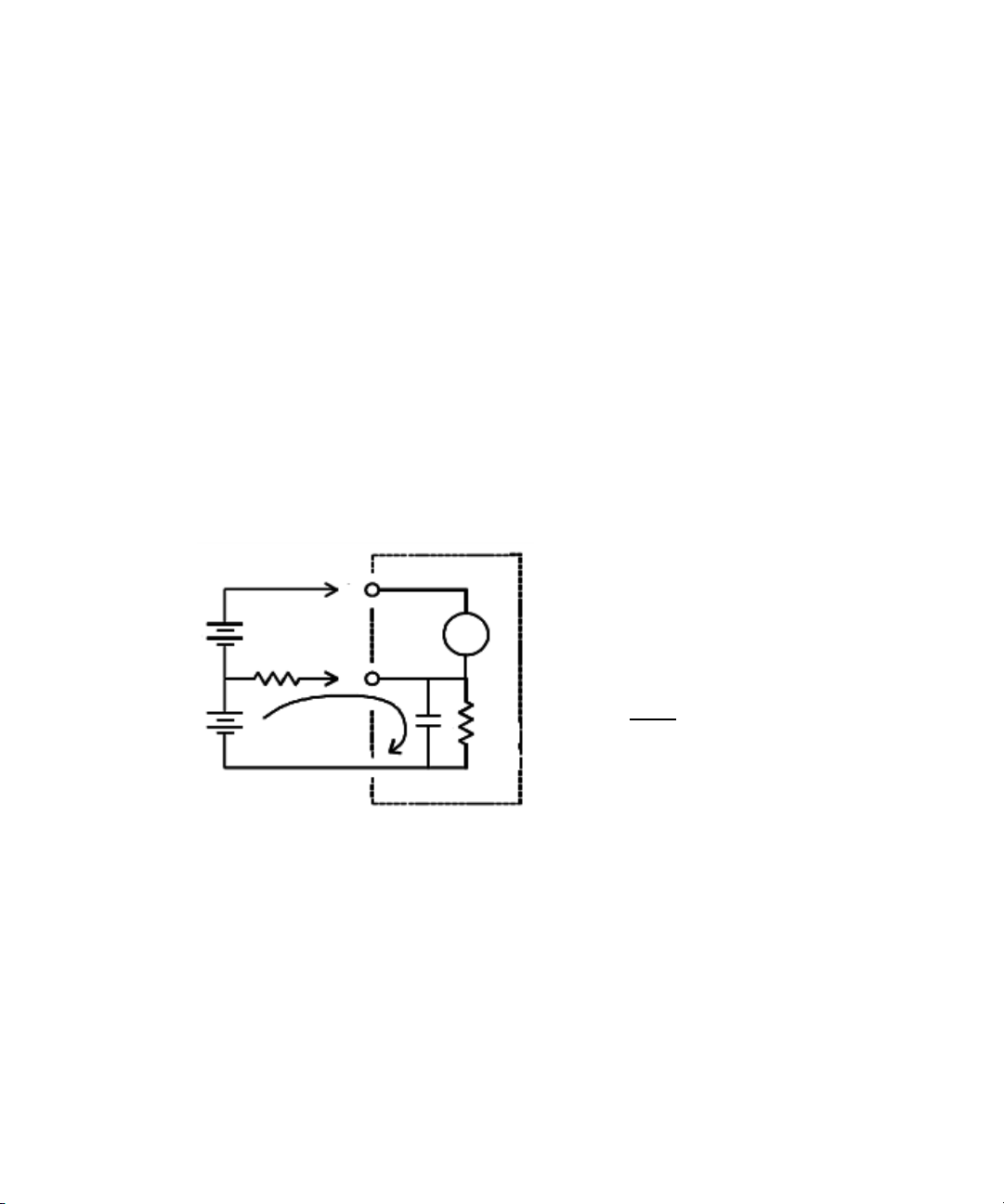
Vf = Float Voltage
R
s
= DUT Source Resistance Imbalance
R
i
= digital mul timeter Isolation Resistance
C
i
= digital mul timeter Input Capacitance
Error (v) =
R
s
+ R
i
V
f
R
i
Rs
C
i
LO
HI
Ideal
Meter
V
test
Vf x R
s
(LO-Earth)
Rejecting power-line noise voltages
An important property of integrating analog-to-digital (A/D) converters is their
ability to reject power-line related noise that is present on the DC input signals.
This is called normal mode noise rejection, or NMR. The digital multimeter
achieves NMR by measuring the average DC input by “integrating” it over an
integral number of power line cycles.
Common mode rejection (CMR)
Ideally, a digital multimeter is completely isolated from earth-referenced circuits.
However, there is a finite resistance between the digital multimeter's input LO
terminal and earth ground, as shown below. This can cause errors when
measuring low voltages that are floating in relative to earth ground.
Measurement Tutorial 3
Figure 3-1 Common mode source error
Keysight U2741A User’s Guide 49
Page 50

3Measurement Tutorial
Noise caused by magnetic loops
If you are making measurements near magnetic fields, it is a good practice to
avoid inducing voltages in the measurement connections. Conductor carrying
high current is one common source of magnetic field. You can use twisted-pair
cable connections to the digital multimeter to reduce the noise pickup loop area,
or place the test leads as close together as possible. Loose or vibrating test leads
will also induce error voltages. Tie test leads securely when operating near
magnetic fields. Whenever possible, use magnetic shielding materials or increase
the distance from magnetic sources to minimize this error.
Noise caused by ground loops
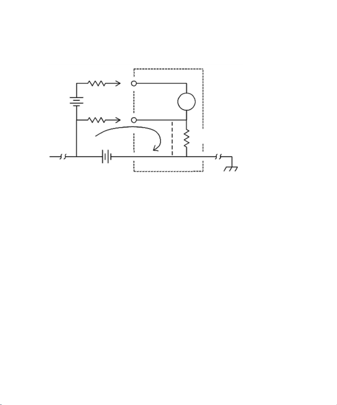
When measuring voltages in circuits where the digital multimeter and the device
under test are both referenced to a common earth ground, a ground loop is
formed. As shown in Figure 3-2, any voltage difference between the two ground
reference points (V
leads. This gives rise to noise and offset voltage (usually power-line related),
which are added to the measured voltage.
) will cause a current to flow through the measurement
ground
50 Keysight U2741A User’s Guide
Page 51
Measurement Tutorial 3
RL = Lead Resistance
R
i
= digital multimeter Isolation
V
ground
= Voltage Drop or Ground Bus
R
L
Ri > 10 GΩ
V
ground
R
L
V
test
LO
HI
Meter
Ideal
Resistance
Figure 3-2 Ground loop induced error
The best way to eliminate ground loops is to isolate the digital multimeter from
earth by not grounding the input terminals. If the digital multimeter must be
earth-referenced, connect it and the device under test to the same common
ground point. Also connect the digital multimeter and device under test to the
same electrical outlet whenever possible.
Keysight U2741A User’s Guide 51
Page 52

3Measurement Tutorial
Resistance Measurement Considerations
When measuring resistance, the test current flows from the input HI terminal
through the resistor being measured. The voltage drop across the resistor being
measured is sensed internally in the digital multimeter. Therefore, the test lead
resistance is also measured.
The errors mentioned earlier in this chapter for DC voltage measurements also
apply to resistance measurements. Additional error sources unique to resistance
measurements are discussed here.
Resistance measurements
The Keysight U2741A offers two methods for measuring resistance:
2-wire and 4-wire ohms. For both methods, the test current flows from the input
HI terminal and then through the resistor being measured. For 2-wire ohms, the
voltage drop across the resistor being measured is sensed internal to the digital
multimeter. Therefore, test lead resistance is also measured. For 4-wire ohms,
separate “sense” connections are required. Since no current flows in the sense
leads, the resistance in these leads does not give a measurement error.
The errors mentioned earlier in this chapter for DC voltage measurements also
apply to resistance measurements. Additional error sources unique to resistance
measurements are discussed on the following pages.
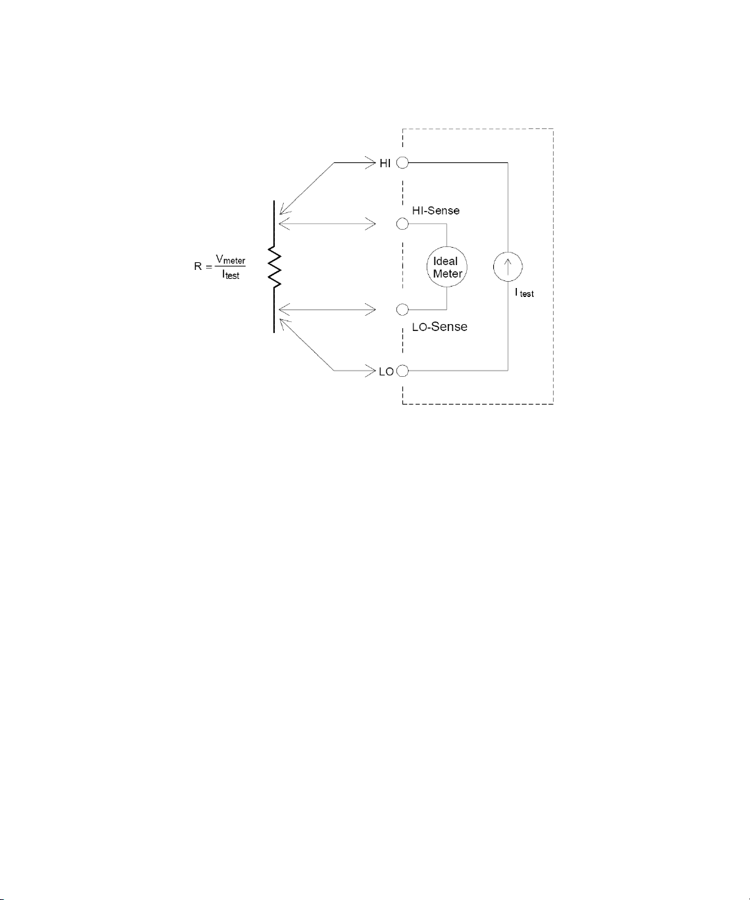
4-wire ohms measurements
The 4-wire ohms method provides the most accurate way to measure small
resistances. Test lead resistances and contact resistances are automatically
reduced using this method. Four-wire ohms is often used in automated test
applications where long cable lengths, numerous connections, or switches exist
between the digital multimeter and the device-under-test. The recommended
connections for 4-wire ohms measurements are shown below.
52 Keysight U2741A User’s Guide
Page 53
Measurement Tutorial 3
Removing test lead resistance errors
To eliminate offset errors associated with the test lead resistance in 2-wire ohms
measurements, follow the steps below.
1 Short the tips of the test leads. The reading is the test lead resistance.
2 Click Null. The digital multimeter stores the test lead resistance as the 2-wire
resistance null value and the digital multimeter will subtract this value from
the value of subsequent measurements.
Minimizing power dissipation effects
When measuring resistors designed for temperature measurements (or other
resistive devices with large temperature coefficients), be aware that the digital
multimeter will dissipate some power in the device under test.
If power dissipation is a problem, you should select the digital multimeter's next
higher measurement range to reduce the errors to acceptable levels. The
following table shows several examples:
Keysight U2741A User’s Guide 53
Page 54

3Measurement Tutorial
Tab le 3-2 Power dissipation for various resistance ranges
Range Test current DUT power at full scale
100 Ω 1 mA 100 mW
1 kΩ 0.83 mA 689 mW
10 kΩ 100 mA 100 mW
100 kΩ 10 mA 10 mW
1 MΩ 900 nA 810 nW
10 MΩ 205 nA 420 nW
100 MΩ 205 nA || 10 MΩ 35 nW
Errors in high resistance measurements
When you are measuring large resistances, significant errors can occur due to
insulation resistance and surface cleanliness. You should take the necessary
precautions to maintain a “clean” high-resistance system. Test leads and fixtures
are susceptible to leakage due to moisture absorption in insulating materials and
“dirty” surface films. Nylon and PVC are relatively poor insulators (10
13
compared to Polytetrafluoroethylene (PTFE) insulators (10
nylon or PVC insulators can easily contribute a 0.1% error when measuring a
Ω resistance in humid conditions.
1 M
Ω). Leakage from
9
Ω) when
54 Keysight U2741A User’s Guide
Page 55
Measurement Tutorial 3
NOTE
2
V
2
-----
V
2
----3
V
3
-----
V
3
-----
T
t
p
-------
V
CF
-----
1
1
CF
-----
⎝⎠
⎛⎞
2
–×
V
CF
-----
1VV
AC Measurements
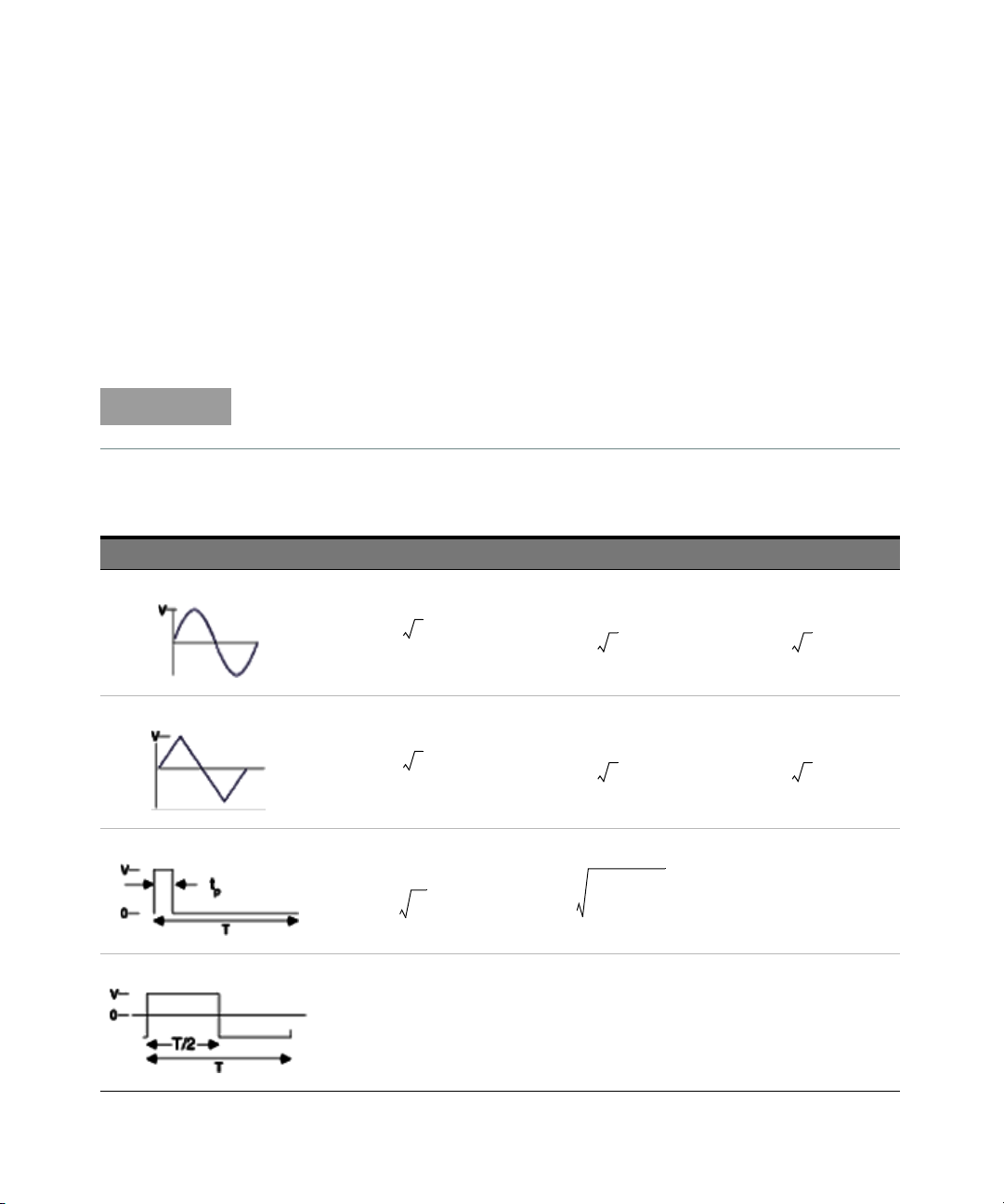
True RMS AC measurements
True RMS responding digital multimeter, like the U2741A, measure the “heating”
potential of an applied voltage. Power dissipated in a resistor is proportional to
the square of the voltage waveform. This digital multimeter accurately measures
true RMS voltage or current, as long as the wave shape contains negligible energy
above the instrument's effective bandwidth.
The U2741A uses the same techniques to measure true RMS voltage and true
RMS current.
Table 3-3 Waveform shapes and their parameters
Waveform shape Crest factor (CF) AC RMS AC+DC RMS
Keysight U2741A User’s Guide 55
Page 56

3Measurement Tutorial
AC DC+()
TrueRMS
AC2DC
2
+=
The digital multimeter's AC voltage and AC current functions measure the
AC-coupled true RMS value, where only the “heating value” of only the AC
components of the input waveform is measured while the DC component is
rejected. As seen in the figure above; for sine waves, triangular waves, and square
waves, the AC-coupled and AC+DC values are equal, since these waveforms do
not contain a DC offset. However, for non-symmetrical waveforms, such as pulse
trains, there is a DC voltage content, which is rejected by Keysight's AC-coupled
true RMS measurements. This can provide a significant benefit. An AC-coupled
true RMS measurement is desirable when you are measuring small AC signals in
the presence of large DC offsets.
A good example is measuring AC ripples that are present in DC power supplies.
There are situations, however, where you might want to know the AC+DC true
RMS value. You can determine this value by combining results from DC and AC
measurements, as shown below (Equation 1):
For the best AC noise rejection, you should perform the DC measurement at
20 NPLC.
(1)
56 Keysight U2741A User’s Guide
True RMS accuracy and high-frequency signal content
A common misconception is that “since an AC digital multimeter is true RMS, its
sine wave accuracy specifications apply to all waveforms.” Actually, the shape of
the input signal can dramatically affect the measurement accuracy especially
when that input signal contains high-frequency components which exceed the
instrument's bandwidth.
Page 57

Other Primary Measurement Functions
Frequency measurement errors
The U2741A uses a reciprocal counting technique to measure frequency. This
method generates a constant measurement resolution for any input frequency. All
frequency counters are susceptible to errors when measuring low-voltage,
low-frequency signals. The effects of both internal noise and external noise pickup
are critical when measuring “slow” signals. The error is inversely proportional to
frequency. Measurement errors also occur if you attempt to measure the
frequency of an input following a DC offset voltage change and therefore, you
must allow the digital multimeter’s input to fully settle before making frequency
measurements.
DC current measurements
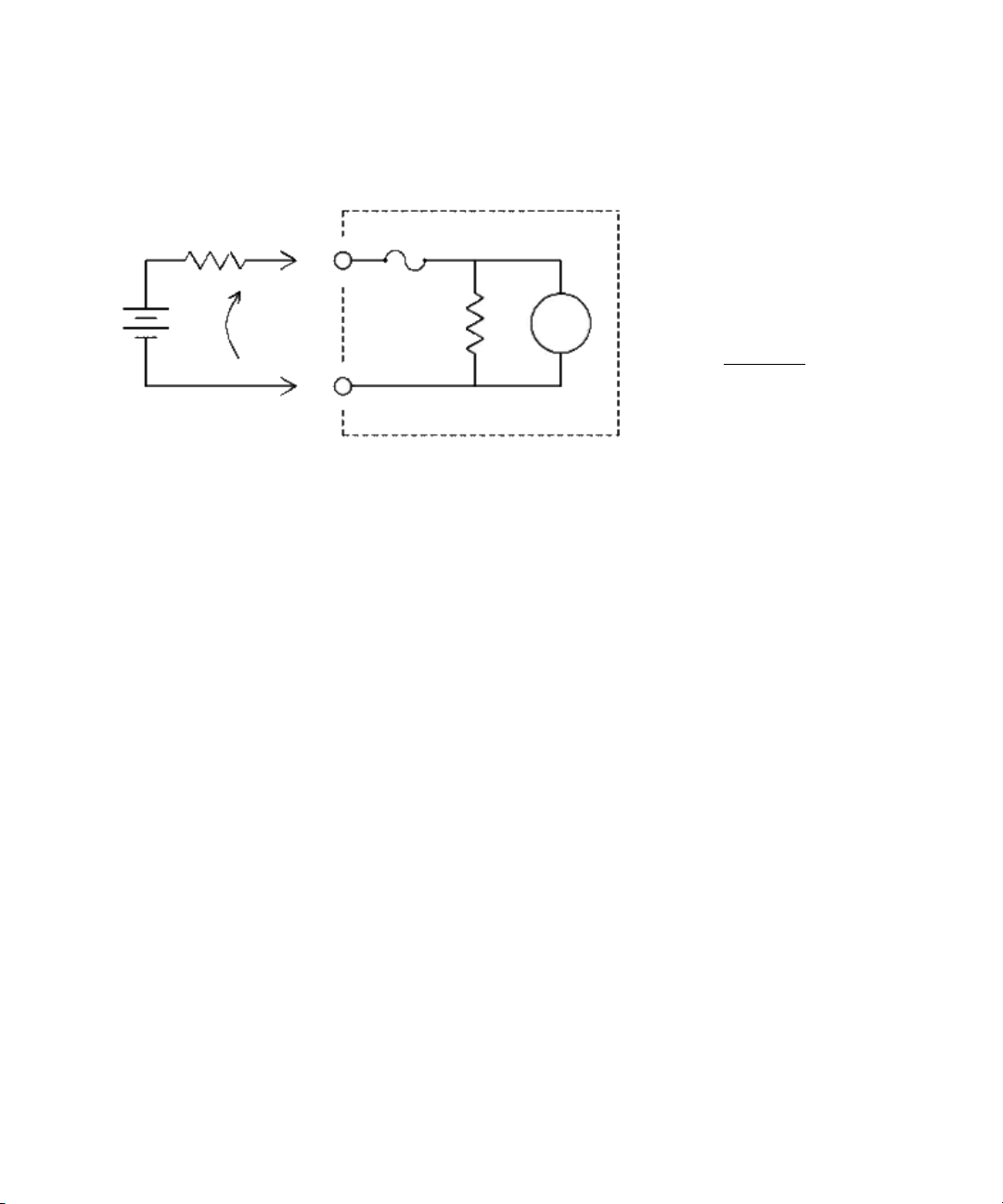
When you connect the digital multimeter in series with a test circuit to measure
current, a measurement error is introduced. The error is caused by the digital
multimeter's series burden voltage. A voltage is developed across the wiring
resistance and current shunt resistance of the digital multimeter, as shown below.
Measurement Tutorial 3
Keysight U2741A User’s Guide 57
Page 58
3Measurement Tutorial
V
b
R
s
LO
HI
R
Ideal
M
e
t
e
r
V
s
Error(%) =
–100%
× V
b
V
s
Vs = Source Voltage
R
s
= DUT Source Resistance
V
b
= digital mul timeter Burden
R = digital multimeter Current Shunt
Voltage
Figure 3-3 Burden voltage in current measurement
58 Keysight U2741A User’s Guide
Page 59

Other Sources of Measurement Error
Error %()
100– R
s
×
R
s
1 MΩ+
--------------------=
Error %() 100
1
12π FR
s
Cin×××()+
----------------------------------------------1–×=
Rs = Source resistance
F = Input frequency
C
in
= Input capacitance (100 pF) plus cable capacitance
Loading errors (AC volts)
In the AC voltage function, the input of the digital multimeter appears as a 1 MΩ
resistance in parallel with 100 pF of capacitance. The cabling that you use to
connect signals to the digital multimeter also adds capacitance and loading.
For low frequencies, the loading error is (Equation 2):
At high frequencies, the additional loading error is (Equation 3):
Measurement Tutorial 3
(2)
(3)
Measurements below full scale
You can make the most accurate AC measurements when the digital multimeter is
at or near the full scale of the selected range. Autoranging occurs at 10%
(down-range) and 120% (up-range) of full scale. This enables you to measure
some inputs at full scale on one range and 10% of full scale on the next higher
range. In general, the accuracy is better on the lower range; for the highest
accuracy, select the lowest manual range possible for the measurement.
High-voltage self-heating errors
If you apply more than 300 Vrms, self-heating occurs in the digital multimeter's
internal signal-conditioning components. These errors are included in the digital
multimeter's specifications.
Temperature changes inside the digital multimeter due to self-heating may cause
additional error on other AC voltage ranges.
Keysight U2741A User’s Guide 59
Page 60

3Measurement Tutorial
Voltage Measured V
in
2
Noise
2
+=
AC current measurement errors (burden voltage)
Burden voltage errors, which apply to DC current, also apply to AC current
measurements. However, the burden voltage for AC current is larger due to the
digital multimeter's series inductance and your measurement connections. The
burden voltage increases as the input frequency increases. Some circuits may
oscillate when performing current measurements due to the digital multimeter's
series inductance and your measurement connections.
Low-level measurement errors
When measuring AC voltages less than 100 mV, be aware that these
measurements are especially susceptible to errors introduced by extraneous noise
sources. An exposed test lead acts as an antenna and a properly functioning
digital multimeter will measure the signals received. The entire measurement
path, including the power line, acts as a loop antenna. Circulating currents in the
loop create error voltages across any impedance in series with the digital
multimeter's input. For this reason, you should apply low-level AC voltages to the
digital multimeter through shielded cables. You should connect the shield to the
input LO terminal.
Make sure the digital multimeter and the AC source are connected to the same
electrical outlet whenever possible. You should also minimize the area of any
ground loops that cannot be avoided. A high-impedance source is more
susceptible to noise pickup than a low-impedance source. You can reduce the
high-frequency impedance of a source by placing a capacitor in parallel with the
digital multimeter's input terminals. You may have to experiment to determine the
correct capacitor value for your application.
Most extraneous noise is not correlated with the input signal. You can determine
the error as shown below (Equation 4):
60 Keysight U2741A User’s Guide
Correlated noise, while rare, is especially detrimental. Correlated noise always
adds directly to the input signal. Measuring a low-level signal with the same
frequency as the local power line is a common situation that is prone to this error.
(4)
Page 61

Keysight U2741A USB Modular 5.5 Digits Digital Multimeter
User’s Guide
4 Characteristics and
Specifications
For the characteristics and specifications of the U2741A USB Modular 5.5 Digits
Digital Multimeter, refer to the datasheet at
http://literature.cdn.keysight.com/litweb/pdf/5991-0042EN.pdf.
61
Page 62

4 Characteristics and Specifications
THIS PAGE HAS BEEN INTENTIONALLY LEFT BLANK.
62 Keysight U2741A User’s Guide
Page 63

This information is subject to change
without notice. Always refer to the
Keysight website for the latest
revision.
© Keysight Technologies 2008 - 2017
Edition 10, March 17, 2017
Printed in Malaysia
*U2741-90001*
 Loading...