


Keysight U1281A/
U1282A Handheld
Digital Multimeter
Quick Start Guide

Safety Notices
CAUTION
WARNING
CAT III
1000 V
CAT IV
600 V
A CAUTION notice denotes a
hazard. It calls attention to an
operating procedure, practice, or
the like that, if not correctly
performed or adhered to, could
result in damage to the product
or loss of important data. Do not
proceed beyond a CAUTION
notice until the indicated
conditions are fully understood
and met.
Safety Information
The U1281A/U1282A is
safety-certified in compliance with
IEC/EN 61010-1, IEC/EN
61010-2-030, IEC/EN
61010-2-033, CAN/CSA-C22.2 No.
61010-1, CAN/CSA-C22.2 No.
61010-2-030, CAN/CSA-C22.2 No.
61010-2-033, UL Std. No.
61010-1, UL Std. No. 61010-2-030
and UL Std. No. 61010-2-033. Use
with standard or compatible test
probes.
Safety symbols
Direct current (DC)
A WARNING notice denotes a
hazard. It calls attention to an
operating procedure, practice, or
the like that, if not correctly
performed or adhered to, could
result in personal injury or
death. Do not proceed beyond a
WARNING notice until the
indicated conditions are fully
understood and met.
EMC Information
The U1281A/U1282A is
EMC-certified in compliance with
IEC 61326-1/EN 61326-1,
CISPR11/EN55011 Group 1 Class
A, ICES/NMB-001, and AS/NZS
CISPR 11.
Alternating current (AC)
Caution, risk of danger
(refer to this manual for
specific Warning or
Caution information)
Earth (ground) terminal
Equipment protected
throughout by double
insulation or reinforced
insulation
Category III 1000 V
overvoltage protection
Category IV 600 V
overvoltage protection
For further safety information details, refer to the
Keysight U1281A/U1282A Handheld Digital Multimeter
User’s Guide.
2 Keysight U1281A/U1282A Quick Start Guide

Standard Shipped Items
NOTE
NOTE
Verify that you have received the following items
with the shipment of your U1281A/U1282A
multimeters:
✔ Test probes
✔ Infrared (IR)-to-USB cable
✔ AA batteries (4x)
✔ Certificate of Calibration
If any item is missing or damaged, keep the
shipping materials and contact the nearest Keysight
Sales Office.
– The descriptions and instructions in this guide
apply to the U1281A and U1282A Handheld
Digital Multimeters.
– The model U1282A appears in all illustrations.
– All related documents and software are
available for download at
www.keysight.com/find/hhTechLib.
Your multimeter is capable of receiving remote
commands and performing remote data logging. To
use these features, you will need either an
IR-to-USB cable (included in the shipment) or an
IR-to-Bluetooth
separately), and the Keysight Handheld Meter
Logger Software (downloadable from
www.keysight.com/find/hhmeterlogger).
For more information on the remote commands,
refer to the U1281A/U1282A Programming Guide.
®
adapter (U1117A, purchased
Keysight U1281A/U1282A Quick Start Guide 3

Install or Change the Batteries
A
m
A
C
O
M
V
V
A
V
m
V
m
V
U
1
2
8
2
A
T
r
u
e
R
M
S
M
u
l
t
i
m
e
t
e
r
m
A
P
e
a
k
V
s
e
n
s
e
D
u
a
l
A
u
t
o
F
U
S
E
D
4
4
0
m
A
C
A
T
I
I
I
1
0
0
0
V
6
0
0
V
C
A
T
I
V
M
A
X
1
0
A
M
A
X
F
U
S
E
D
O
U
T
O
U
T
M
H
z
R
M
T
U
1
2
8
2
A
T
r
u
e
R
M
S
M
u
l
t
i
m
e
t
e
r
U
1
2
8
2
A
T
r
u
e
R
M
S
M
u
l
t
i
m
e
t
e
r
V
s
e
n
s
e
P
e
a
k
V
s
e
n
s
e
D
u
a
l
A
u
t
o
V
m
V
O
U
T
M
H
z
m
A
A
V
m
V
A
C
O
M
V
F
U
S
E
D
4
4
0
m
A
C
A
T
I
I
I
1
0
0
0
V
6
0
0
V
C
A
T
I
V
M
A
X
1
0
A
M
A
X
F
U
S
E
D
O
U
T
R
M
T
A
m
A
C
O
M
V
V
A
V
m
V
m
V
T
r
u
e
R
M
S
M
u
l
t
i
m
e
t
e
r
m
A
P
e
a
k
V
s
e
n
s
e
D
u
a
l
A
u
t
o
F
U
S
E
D
4
4
0
m
A
C
A
T
I
I
I
1
0
0
0
V
6
0
0
V
C
A
T
I
V
M
A
X
1
0
A
M
A
X
F
U
S
E
D
O
U
T
O
U
T
M
H
z
R
M
T
T
r
u
e
R
M
S
M
u
l
t
i
m
e
t
e
1 2
6
3
4 5
7 8
V
A
V
mV
mV
mA
OUT
MHz
The multimeter is powered by four 1.5 V AA
batteries (included in the shipment).
Before installing or changing the batteries, pull from
a corner and stretch the orange rubber holster to
remove it.
Turn On the Multimeter
Turn the rotary switch from the position to any
other position to begin making measurements.
4 Keysight U1281A/U1282A Quick Start Guide

The Multimeter at a Glance
A
mA
COM
V
V
A
V
mV
mV
U1282A
True RMS Multimeter
mA
Vsense
Peak
Vsense
Dual
Auto
FUSED
440mA
CAT III 1000V
600VCAT IV
MAX
10A MAX
FUSED
OUT
OUT
MHz
RMT
Vsense red LED indicator
Display screen
Keypad
Rotary switch
Input terminals
IR communication port
Test lead/probe holders
Battery access
(under the orange rubber holster)
Tilt stand
Fuse access
(under the orange rubber holster)
Keysight U1281A/U1282A Quick Start Guide 5

Using the Rotary Switch
V
mV
V
mV
MHz
mA
A
OUT
WARNING
Legend Measurement function
AC V/AC V with Low Pass Filter (LPF)
AC mV/AC mV with LPF
DC/AC/AC+DC V ✔✔
DC/AC/AC+DC mV ✔✔
Resistance/Continuity ✔✔
Diode/Frequency counter
Capacitance/Temperature ✔✔
DC μA/mA/AC μA/mA/AC+DC μA/mA ✔✔
DC A/AC A/AC+DC A ✔✔
Square wave mode
[a]
Model
U1281A U1282A
[a]
✔✔
[a]
[a]
✔✔
✔✔
— ✔
[a] For U1282A only.
Remove the test leads from the measuring source
or target before changing the rotary switch
position.
Refer to the U1281A/U1282A User’s Guide for a
complete list and description of all rotary switch
labels.
6 Keysight U1281A/U1282A Quick Start Guide

Using the Keypad
MaxMin
Vsense
Range
Hz
Save
Esc
Shift
Hold
Legend
Key response when pressed for:
Less than 1 second More than 1 second
– Starts the Max/Min/Avg
record ing
– Switches between the
Max/Min/Avg recording
modes
– Stops the Max/Min/Avg
record ing
– Starts and stops the
Peak recording
Enables and disables the
Sets the Null/Relative mode
non-contact vol tage
detection – Vsense
Sets a manual range Enables autoranging
Enables the frequency test
mode for current or voltage
measurements
Starts and stops data
logging
Activates and deactivates
Turns the backlight on/off
the dual d isplay mode (if
supported by the
measurement)
Switches between the
regular and shifted (icons
printed in orange) functions
Enters the Log Review
menu
– Freezes the present
reading in the d isplay
(TrigHold mode)
– Automatically freezes the
present reading when
certain cond itions are met
(AutoHold mode; when
enabled from the
multimeter’s Setup mode)
Exits the TrigHold mode
– Exits the AutoHold mode
– Stores a record of the
measured signal and
exports it via the
multimeter’s optical
communication port
[a]
[a] For the U1282A only
Keysight U1281A/U1282A Quick Start Guide 7

Using the Input Terminals
WARNING
V
V
COM
mV
V
mV
MHz
mA
mA
COM
A
A
COM
OUT
RMT
Hold
To avoid damaging this device, do not exceed the
input limit.
Rotary
position
Input terminals Overload protection
1000 Vrms
1000 Vrms for short
circuit <0.3 A
440 mA/1000 V,
fast-acting fuse
11 A/1000 V,
fast-acting fuse
This input terminal is for use with the Remote Switch Probe (purchased
separately). The button on the probe emulates the button on the
multimeter by default.
8 Keysight U1281A/U1282A Quick Start Guide

Safety Alerts and Warnings
CAUTION
Hazardous voltage indication
The multimeter will display the hazardous voltage
( ) symbol as an early precaution when the
measured voltage is:
Measurement DC AC
V (mV) ≥ +30 V or +OL ≤ –30 V or –OL ≥ 30 V or OL
This symbol will also be displayed when the input
signal exceeds the limitation of measuring circuit as
frequency dependence.
Hazardous current indication
The multimeter will display the hazardous current
( ) symbol as an early precaution when the
measured current has reached the maximum fuse
rating as follows:
Measurement DC AC
A ≥ +11 A or +OL ≤ –11 A or –OL ≥ 11 A or OL
μA/mA ≥ 440 mA or +OL ≤ –440 mA or –OL ≥ 440 mA or OL
If your measuring current is > 10 A ~ 19.999 A, you
will need to lower the current within a 30-second
time limitation to avoid blowing the multimeter’s
fuse.
Keysight U1281A/U1282A Quick Start Guide 9

Input Warning
A
mA
The multimeter emits a continuous beep and the
red LED indicator lights up when:
– the test lead is inserted into the
input terminal but the rotary switch is not set to
the correct current position. The secondary
display will show
test lead is removed. The beeping will stop
automatically after 5 seconds even if the test
lead is not removed.
– the rotary switch is set to the current
measurement position but no lead is inserted
into its respective input terminal. The secondary
display will show and the warning alert
will stop after approximately 3 seconds.
or
or until the
10 Keysight U1281A/U1282A Quick Start Guide

Voltage Measurements
A
mA
COM
V
V
A
V
mV
mV
U1282A
True RMS Mul ti met er
mA
Vsense
Peak
Vsense
Dual
Auto
FUSED
440mA
CAT III1000V
600VCAT IV
MAX
10AMAX
FUSED
OUT
OUT
MHz
RMT
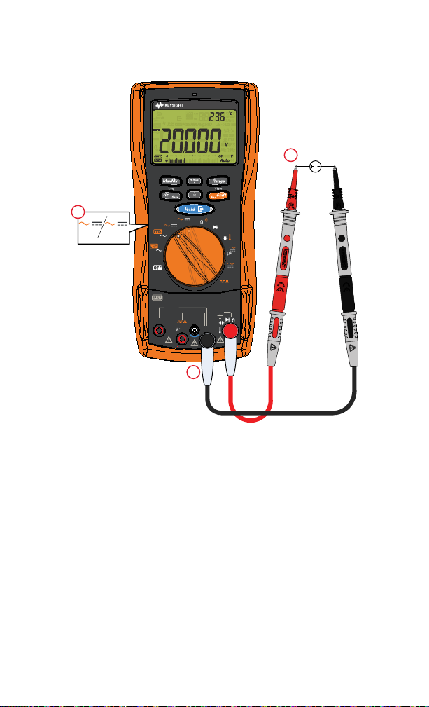
1
AC
3
2
mV
V
Measuring AC voltage
Keysight U1281A/U1282A Quick Start Guide 11
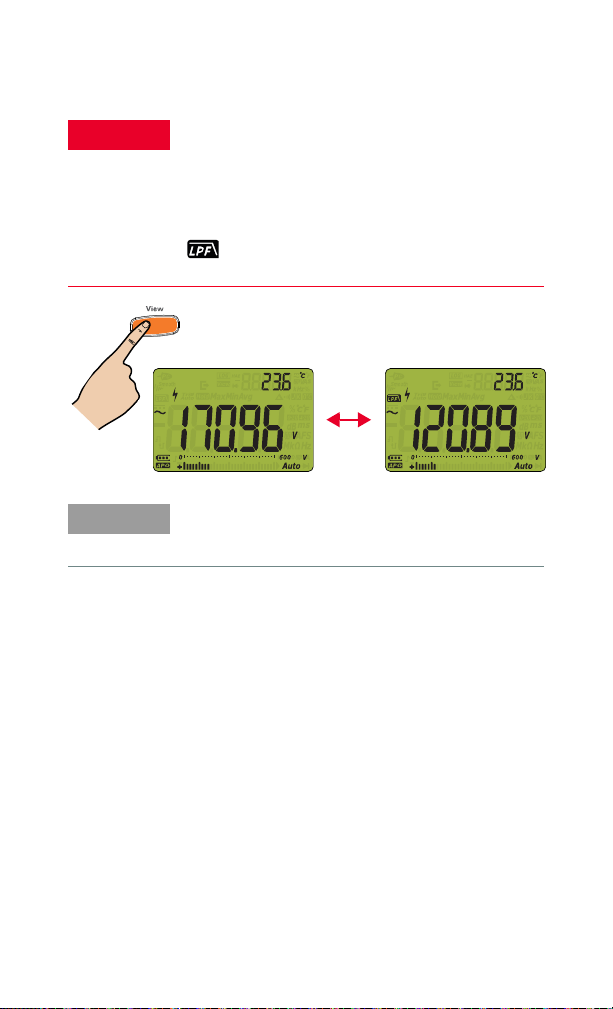
Using the AC low-pass filter (LPF)
WARNING
Esc
Shift
NOTE
To avoid possible electric shock or personal injury,
ensure that you are aware of the voltage level
without the LPF enabled. There may be a possible
presence of hazardous voltage, and voltages
measured with the LPF enabled may be greater
than indicated. For your safety, take note of the
symbol. Disable the LPF when you have
completed your measurement.
The LPF can improve measurement performance on
composite sine waves that are typically generated
by inverters and variable frequency motor drives.
12 Keysight U1281A/U1282A Quick Start Guide
Measuring DC voltage
A
mA
COM
V
V
A
V
mV
mV
U1282A
True R MS Mu lt im ete r
mA
Vsense
Peak
Vsense
Dual
Auto
FUSED
440mA
CAT III1000V
600VCAT IV
MAX
10AMAX
FUSED
OUT
OUT
MHz
RMT
1
DC
3
2
V
mV
Keysight U1281A/U1282A Quick Start Guide 13

Current Measurement
WARNING
CAUTION
A
mA
COM
V
V
A
V
mV
mV
U1282A
TrueRMS Multimeter
mA
Vsense
Peak
Vsense
Dual
Auto
FUSED
440mA
CAT III1000V
600VCAT IV
MAX
10AMAX
FUSED
OUT
OUT
MHz
RMT
1
LOAD
3
AC
2
A
mA
Esc
Shift
Measuring AC/DC current
Never attempt an in-circuit current measurement
where the open-circuit potential to earth is greater
than 1000 V.
Current can be measured up to 440 mA (maximum)
continuously. You can measure current more than
440 mA and up to 600 mA for 20 hours maximum.
14 Keysight U1281A/U1282A Quick Start Guide

Measuring voltage frequency
Hz
SaveHzSave
Hz
Save
Measuring current frequency
Measuring frequency/duty cycle/pulse width
Keysight U1281A/U1282A Quick Start Guide 15

Frequency Counter (U1282A only)
WARNING
A
mA
COM
V
V
A
V
mV
mV
U1282A
TrueRMS Multimeter
mA
Vsense
Peak
Vsense
Dual
Auto
FUSED
440mA
CAT III1000V
600VCAT IV
MAX
10AMAX
FUSED
OUT
OUT
MHz
RMT
AC
1
4
2
3
Esc
Shift
MHz
If the reading is zero or
unstable, press to
toggle between a Hz or
MHz reading.
Range
– Use the frequency counter for low voltage
applications. Never use the frequency counter
on AC power line systems.
– For input more than 3.6 Vpp, you are required
to use the frequency measurement mode
available under the current or voltage
measurement instead of the frequency
counter.
16 Keysight U1281A/U1282A Quick Start Guide

Resistance Measurement
A
mA
COM
V
V
A
V
mV
mV
U1282A
True RMS Multimeter
mA
Vsense
Peak
Vsense
Dual
Auto
FUSED
440mA
CAT III 1000V
600VCAT IV
MAX
10A MAX
FUSED
OUT
OUT
MHz
RMT
1
3
2
Vsense
1
2
Removing test lead resistance
Keysight U1281A/U1282A Quick Start Guide 17

Continuity Tests
CAUTION
A
mA
COM
V
V
A
V
mV
mV
U1282A
TrueRMS Multimeter
mA
Vsense
Peak
Vsense
Dual
Auto
FUSED
440mA
CAT III1000V
600VCAT IV
MAX
10AMAX
FUSED
OUT
OUT
MHz
RMT
ON
(closed)
OFF
(open)
4
1
3
2
Esc
Shift
If resistance < threshold, beeper
sounds and red LED indicator
lights up
To avoid possible damage to the mul timeter or to
the equipment under test, disconnect circuit power
and discharge all high-voltage capacitors before
measuring continuity. Use the DC voltage function
to confirm that the capacitor is fully discharged.
18 Keysight U1281A/U1282A Quick Start Guide
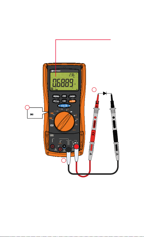
Diode Tests
A
mA
COM
V
V
A
V
mV
mV
U1282A
True RMS Multimeter
mA
Vsense
Peak
Vsense
Dual
Auto
FUSED
440mA
CAT III 1000V
600VCAT IV
MAX
10A MAX
FUSED
OUT
OUT
MHz
RMT
1
3
2
MHz
The beeper will emit a:
– continuous beep (for 0.3 V to 0.8 V)
– repeated beep (for <0.05 V)
Forward bias
Keysight U1281A/U1282A Quick Start Guide 19

Reverse bias
A
mA
COM
V
V
A
V
mV
mV
U1282A
True RMS Multimeter
mA
Vsense
Peak
Vsense
Dual
Auto
FUSED
440mA
CAT III 1000V
600VCAT IV
MAX
10A MAX
FUSED
OUT
OUT
MHz
RMT
1
2
MHz
3
20 Keysight U1281A/U1282A Quick Start Guide

Capacitance Measurement
CAUTION
A
mA
COM
V
V
A
V
mV
mV
U1282A
True RMS Mul ti met er
mA
Vsense
Peak
Vsense
Dual
Auto
FUSED
440mA
CAT III1000V
600VCAT IV
MAX
10AMAX
FUSED
OUT
OUT
MHz
RMT
1
3
2
–
+
To avoid possible damage to the mul timeter or to
the equipment under test, disconnect circuit power
and discharge all high-voltage capacitors before
measuring capacitance. Use the DC voltage
function to confirm that the capacitor is fully
discharged.
Keysight U1281A/U1282A Quick Start Guide 21

Temperature Measurement
WARNING
A
mA
COM
V
V
A
V
mV
mV
U1282A TrueRMS Multimeter
mA
Vsense
Peak
Vsense
Dual
Auto
FUSED
440mA
CAT III10 00V
600VCAT IV
MAX
10AMAX
FUSED
OUT
OUT
MHz
RMT
1
4
3
2
Esc
Shift
Do not connect the thermocouple to electrically
live circuits. Doing so will potentially cause fire or
electric shock.
22 Keysight U1281A/U1282A Quick Start Guide
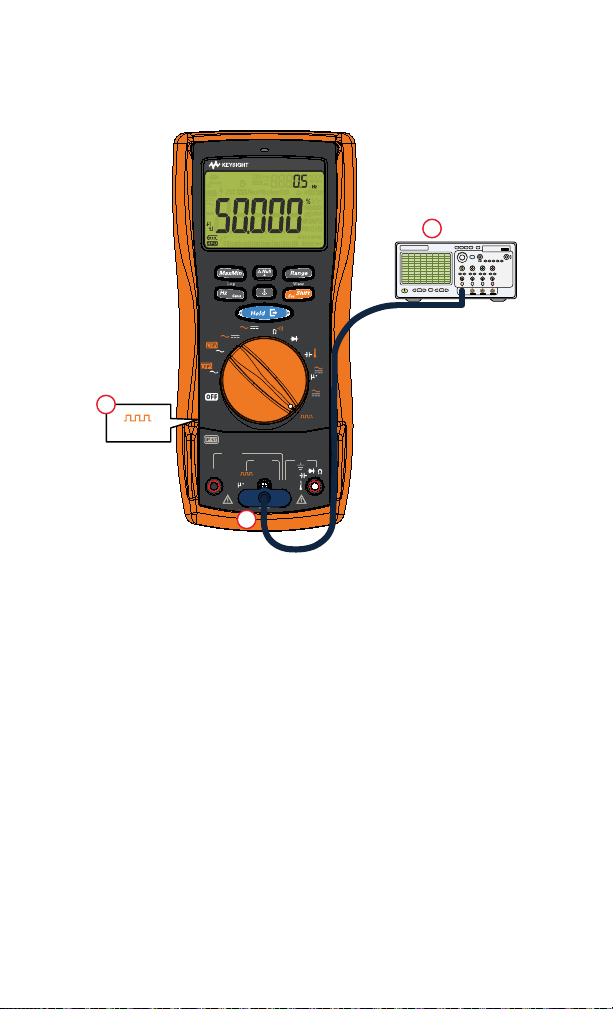
Square Wave Output
A
mA
COM
V
V
A
V
mV
mV
U1282A
True RMS Multimeter
mA
Vsense
Peak
Vsense
Dual
Auto
FUSED
440mA
CAT III 1000V
600VCAT IV
MAX
10A MAX
FUSED
OUT
OUT
MHz
RMT
4321
1
2
OUT
3
oscilloscope
Keysight U1281A/U1282A Quick Start Guide 23

Scrolling between the pulse width/duty cycle
Esc
Shift
Duty cycle
Duty cycle
Pulse width
Pulse width
Setting the pulse width/duty cycle
24 Keysight U1281A/U1282A Quick Start Guide

WARNING
A
mA
COM
V
V
A
V
mV
mV
U1282A
True RMS Mult i met er
mA
Vsense
Peak
Vsense
Dual
Auto
FUSED
440mA
CAT III1000V
600VCAT IV
MAX
10AMAX
FUSED
OUT
OUT
MHz
RMT
2
AC
3
1
>1sec.
V
Vsense
Range
Changing the Vsense
detector’s sensitivity:
Press
+
beeper
sounds
AC voltage source
Non-Contact Voltage Detector (Vsense) (U1282A only)
– Voltage could still be present even if there is
no alert indication. Do not rely on the Vsense
detector with shielded wires. Never touch live
voltage or conductors without the necessary
insulation protection, or power off the voltage
source.
– The Vsense detector may be affected by
differences in socket design, insulation
thickness, and insulation type.
sense
Keysight U1281A/U1282A Quick Start Guide 25

Measurement Data Recording and Review
Hz
Save
> 1 sec
NOTE
Esc
Shift
> 1 sec
Recording measurement data (manual log)
Refer to the U1281A/U1282A User’s Guide for other
data recording options.
Viewing the recorded data
26 Keysight U1281A/U1282A Quick Start Guide

Scrolling through previously stored records
Viewing stored entries
Viewing next and previous stored entries
Keysight U1281A/U1282A Quick Start Guide 27
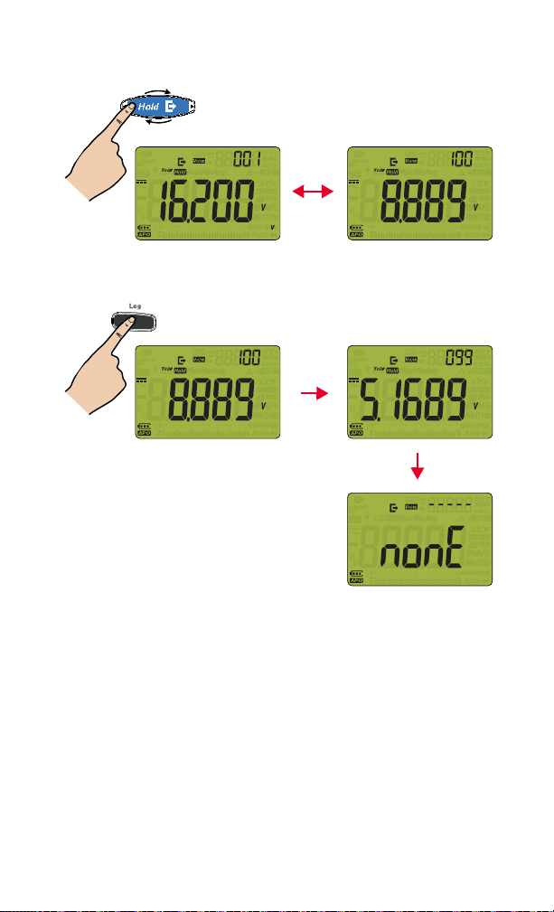
Viewing first and last stored entries
Hz
Save
Clear the last
stored entry
Clear all
stored entries
> 1 sec
Clearing stored entries
28 Keysight U1281A/U1282A Quick Start Guide

This information is subject to change
without notice. Always refer to the
Keysight Web site for the latest
revision.
© Keysight Technologies 2015 - 2021
Edition 3, January 2021
Printed in Malaysia
U1281-90000
www.keysight.com
 Loading...