

Page 1

Keysight U1271A/U1272A
Handheld Digital
Multimeter
Quick Start
Guide
Page 2

CAUTION
WARNING
CAT III
1000 V
CAT IV
600 V
ENGLISH
Contacting Keysight
www.keysight.com/find/assist
(worldwide contact information for
repair and service)
Safety and EMC Information
The U1271A/U1272A is
safety-certified in compliance with
EN/IEC 61010-1, EN/IEC
61010-2-033, CAN/CSA-C22.2
No.61010-1, CAN/CSA-C22.2
No.61010-2-033, UL Std. No.
61010-1/ 61010-2-033, CAT III
1000 V, CAT IV 600 V for pollution
degree 2 environment.
EMC is designed in compliance
with EN 61326-1.
Safety Notices
A CAUTION notice denotes a
hazard. It calls attention to an
operating procedure, practice, or
the like that, if not correctly
performed or adhered to, could
result in damage to the product or
loss of important data. Do not
proceed beyond a CAUTION notice
until the indicated conditions are
fully understood and met.
Safety symbols
Earth (ground) terminal
Equipment protected
throughout by double
insulation or reinforced
insulation
Caution, risk of electric
shock
Caution, risk of danger
(refer to this manual for
specific Warning or Caution
information)
Fuse
Alternating current
Direct current
Battery, general
Category III 1000 V
overvoltage protection
Category IV 600 V
overvoltage protection
A WARNING notice denotes a
hazard. It calls attention to an
operating procedure, practice, or
the like that, if not correctly
performed or adhered to, could
result in personal injury or
death. Do not proceed beyond a
WARNING notice until the
indicated conditions are fully
understood and met.
For further safety information details, refer to the
Keysight U1271A/U1272A Handheld Digital Multimeter User’s Guide.
2 Keysight U1271A/U1272A Quick Start Guide
Page 3

NOTE
Keysight U1271A/U1272A Handheld Digital Multimeter Quick Start Guide
Verify that you received the following items in the
shipment of your multimeter:
✔ Standard test leads
✔ Test probes with 4 mm tips
✔ K-type thermocouple and adapter
✔ 4 x AAA alkaline batteries
✔ Certificate of Calibration
If any item is missing or damaged, keep the
shipping materials and contact the nearest
Keysight Sales Office.
ENGLISH
The descriptions and instructions in this guide apply
to the U1271A and U1272A Handheld Digital
Multimeters.
The model U1272A appears in all illustrations.
All related documents and software are available for
download at www.keysight.com/find/hhTechLib.
Keysight U1271A/U1272A Quick Start Guide 3
Page 4

ENGLISH
Differences between the U1271A and U1272A
The U1272A model offers these additional
functions:
–Z
– Smart Ω measurements
–Auto-diode tests
– AC+DC voltage and current measurements
– J-type thermocouple temperature
– 30 Ω and 300 MΩ ranges for resistance
– dBm and dBV measurements with selectable
– Data logging up to 10,000 memories
The U1271A model has one differing function:
– Qik-V tests
(low input impedance) measurements
LOW
measurements
measurements
impedance
Install the Batteries
Your multimeter is powered by four 1.5 V AAA
alkaline batteries (included with the shipment).
1 Turn the rotary switch to OFF
and remove the test leads
from the terminals.
2 Lift the tilt stand and loosen
the screws with a suitable
Phillips screwdriver.
3 Remove the battery cover and observe the
polarity markings.
4 Insert the batteries and replace the battery
cover and screws.
4 Keysight U1271A/U1272A Quick Start Guide
Page 5

Turn On the Multimeter
NOTE
Display screen
Keypad
Rotary switch
Input terminals
To power ON your multimeter, turn the rotary
switch to any other position.
Your multimeter is capable of remote data logging.
To use this feature, you will need an IR-USB cable
(U1173A, purchased separately) and the Keysight
GUI Data Logger Software (downloadable from
www.keysight.com/find/hhTechLib).
The Multimeter at a Glance
ENGLISH
Keysight U1271A/U1272A Quick Start Guide 5
Page 6

ENGLISH
Test lead/probe holders
IR communication port
Battery access cover
Tilt stand
U1271A U1272A
NOTE
S
h
i
f
t
V
i
e
w
E
s
c
Understanding the Rotary Switch
Press to switch between the shifted and
regular functions.
6 Keysight U1271A/U1272A Quick Start Guide
Page 7

Legend Description
Smart
Auto
AC V with Low Pass Filter
AC mV with Low Pass Filter
DC, (AC, or AC+DC V, U1272A only)
DC, (AC, or AC+DC mV, U1272A only)
Resistance/Continuity/(Smart Ω, U1272A only)
Diode/(Auto-diode, U1272A only)
Capacitance/Temperature
AC, DC, or (AC+DC mA and A, U1272A only)
AC, DC, or (AC+DC μA, U1272A only)
AC/DC V check for signal identification (U1271A only)
(low input impedance) AC/DC V for checking ghost voltages
Z
LOW
(U1272A only)
ENGLISH
Keysight U1271A/U1272A Quick Start Guide 7
Page 8
ENGLISH
S
c
a
l
e
N
u
l
l
P
e
a
k
M
a
x
M
i
n
A
u
t
o
T
r
i
g
H
o
l
d
Exit
Dual
Setup
H
z
%
m
s
L
o
g
A
u
t
o
R
a
n
g
e
S
h
i
f
t
V
i
e
w
E
s
c
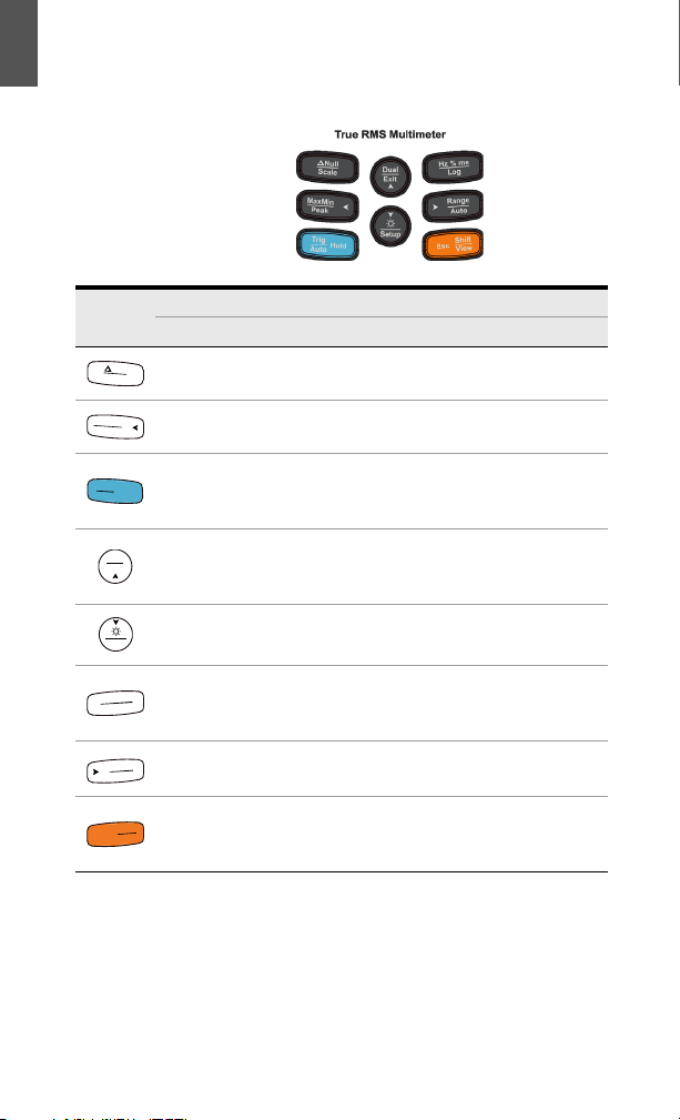
Understanding the Keypad
Legend
Key response when pressed for:
Less than 1 second More than 1 second
Sets the Null/Relative mode.
Starts and stops the MaxMin
recording.
Freezes the present reading in
the display.
Switches between available
dual-combination displays.
Turns the backlight on/off.
Switches between frequency,
pulse width, and duty cycle
measurements.
Sets the Scale mode for the
specified ratio and unit display.
Starts and stops the Peak
record ing.
Automatically freezes the present
reading once the reading is
stable.
Exits the Hold, Null, MaxMin,
Peak, frequency test, and dual
display modes.
Enters/Exits the multimeter’s
setup menu.
Starts and stops the Data
Logging.
Sets a manual range. Enables autoranging.
Switches between the regular
and shifted (icons printed in
Enters the Log Review menu.
orange) functions.
8 Keysight U1271A/U1272A Quick Start Guide
Page 9
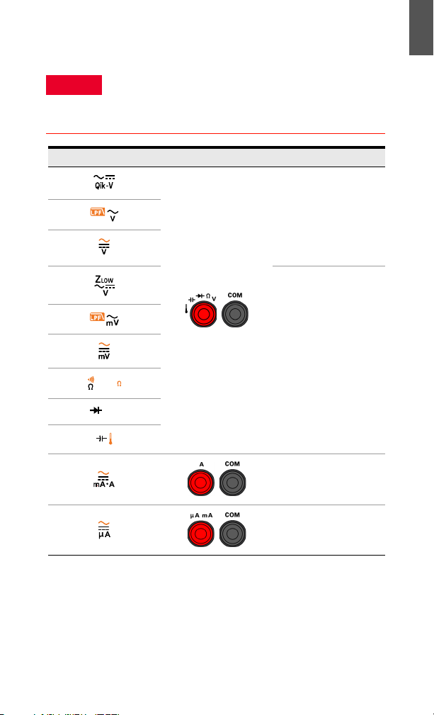
Understanding the Input Terminals
WARNING
Smart
Auto
Ensure that the terminal connections are correct for
that particular measurement function before starting
any measurement. To avoid damage to the device, do
not exceed the input limit.
Rotary position Input terminals Overload protection
1000 Vrms
1000 Vrms for short
circuit <0.3 A
ENGLISH
11 A/1000 V, 30 kA
fast-acting fuse
440 mA/1000 V, 30 kA
fast-acting fuse
Keysight U1271A/U1272A Quick Start Guide 9
Page 10
ENGLISH
U1271A U1272A
DC
Performing Measurements and Tests
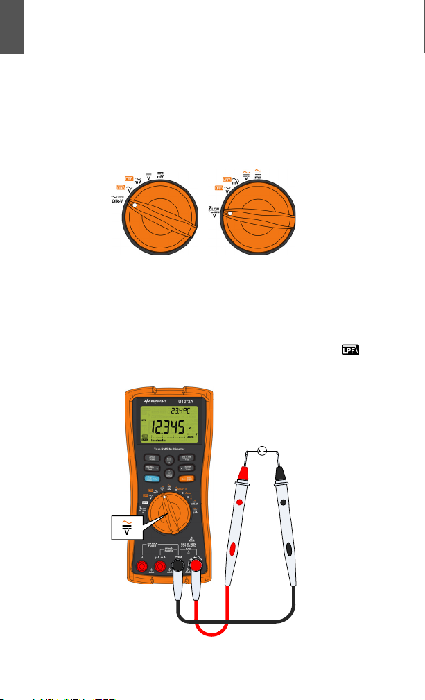
Voltage measurements
The figure below highlights the primary functions
allowing voltage measurements in your
multimeter.
Set up your multimeter as shown in the figure
below to perform voltage measurements. When
measuring DC voltage from a mixed signal in DC
measurement mode, ensure that the Filter ( ) is
enabled.
10 Keysight U1271A/U1272A Quick Start Guide
Page 11
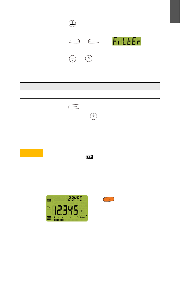
1 Press for more than 1 second to enter the
Setup
P
e
a
k
M
a
x
M
i
n
A
u
t
o
R
a
n
g
e
Exit
Dual
Setup
H
z
%
m
s
L
o
g
Setup
CAUTION
S
h
i
f
t
V
i
e
w
E
s
c
multimeter’s setup menu.
2 Press or until is
shown on the secondary display.
3 Press or to enable the Filter.
Refer to the table below for the respective
firmware versions.
Version 2.00 Version 2.04 or newer
on dC
4 Press to save your changes.
5 Press and hold until the multimeter
restarts and returns to normal operation. Turn
the multimeter to DC Voltage mode to verify
that the LPF symbol is turned on.
ENGLISH
To avoid possible electric shock or personal injury,
enable the Filter (
) to verify the presence of
hazardous DC voltages. Displayed DC voltages can
be influenced by high frequency AC components
and must be filtered to assure an accurate reading.
LPF during AC measurements:
Press while performing AC
voltage measurements to pass the
measured signal through a low pass
filter.
– Passing the measured signal through a LPF
help blocks unwanted voltages such as
electronic noise.
Keysight U1271A/U1272A Quick Start Guide 11
Page 12
ENGLISH
– Use the LPF function to improve measurement
on composite sine waves that are typically
generated by inverters and variable frequency
motor drives.
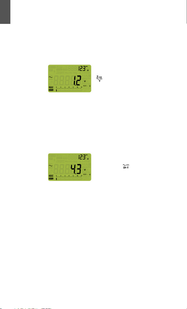
measurements (U1272A only):
Z
LOW
Rotate the rotary switch’s position to
to enable low impedance
measurements.
–Use the Z
(low input impedance) function
LOW
to detect ghost or induced voltages.
– Ghost voltages can be caused by capacitive
coupling between energized wiring and
adjacent unused wiring.
Qik-V test (U1271A only):
Rotate the rotary switch’s
position to to enable the
Qik-V function.
– Use the Qik-V function to quickly identify the
measured signal type.
– Use this function as a reference to determine
if the measured signal is an AC or DC signal,
then select the appropriate voltage
measurement function by turning the rotary
switch to an appropriate position (AC or DC).
12 Keysight U1271A/U1272A Quick Start Guide
Page 13
Resistance measurements
S
h
i
f
t
V
i
e
w
E
s
c
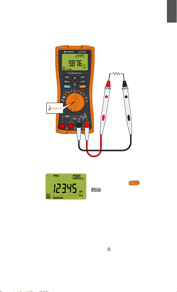
Set up your multimeter as shown in the figure
below to perform resistance measurements.
Smart Ω measurements (U1272A only):
While performing resistance
measurements, press until
is shown on the display to
enable the Smart Ω function.
ENGLISH
– Use the Smart Ω function to measure resistors
affected by DC offset or leakage current.
– If DC offset or bias voltages are detected on
the resistor-under-measure, the offset or bias
DC voltage value will be shown on the
secondary display. If the DC voltage on the
resistor is over +1.25 V, is shown on the
secondary display.
Keysight U1271A/U1272A Quick Start Guide 13
Page 14
ENGLISH
S
h
i
f
t
V
i
e
w
E
s
c
Exit
Dual
ON
(closed)
OFF
(open)
NOTE
Continuity tests
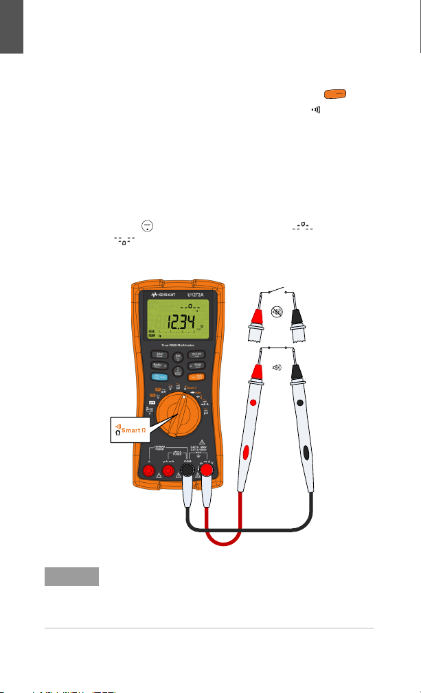
Set up your multimeter as shown in the figure
below to perform continuity tests. Press to
switch to the continuity test function ( is shown
on the display).
You can set the beeper to sound and the
backlight to flash as a continuity indication
whether the circuit-under-test is less than (short)
or more than or equal to (open) the threshold
resistance.
Press to switch between short ( ) and open
( ) states for checking NO (normal open) and
NC (normal close) contacts.
The continuity function detects intermittent shorts
and opens lasting as short as 1 ms. A brief short or
open causes the multimeter to emit a short beep
and flash.
14 Keysight U1271A/U1272A Quick Start Guide
Page 15
Diode tests
S
h
i
f
t
V
i
e
w
E
s
c
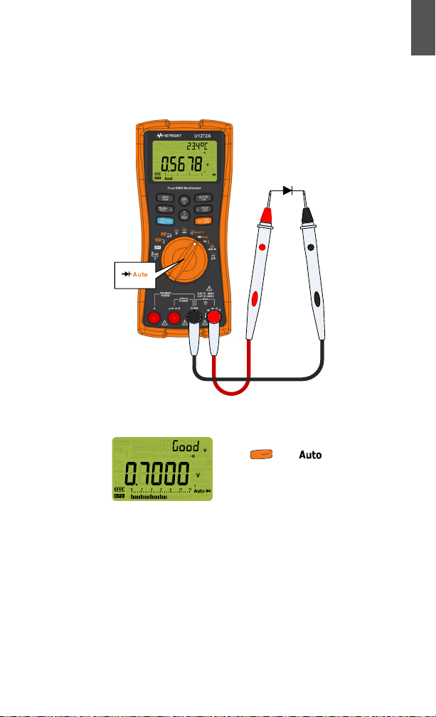
Set up your multimeter as shown in the figure
below to perform diode tests.
Auto-diode tests (U1272A only):
Press until is shown on
the display to use the auto diode
function.
ENGLISH
– The Auto-diode function tests both the
forward bias and reverse bias directions of
your diode simultaneously. The forward bias
voltage is shown on the primary display and
the reverse bias voltage is shown on the
secondary display.
Keysight U1271A/U1272A Quick Start Guide 15
Page 16
ENGLISH
NOTE
– will be indicated briefly on the secondary
display along with a brief beep if the diode is
found to be in good condition. is shown if
the diode is out of the thresholds.
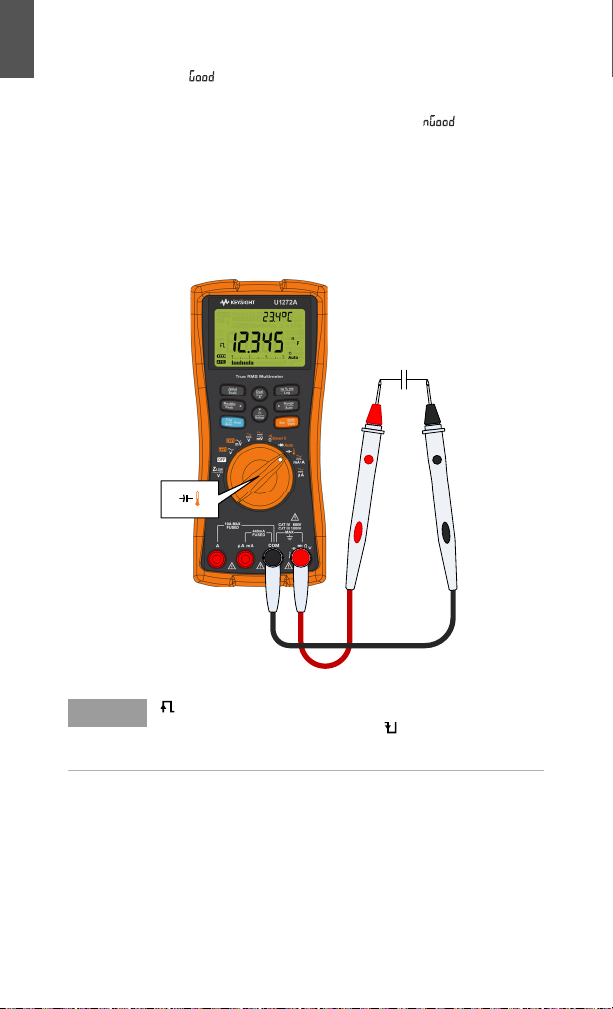
Capacitance measurements
Set up your multimeter as shown in the figure
below to perform capacitance measurements.
is shown on the bottom left of the display when
the capacitor is charging, and is shown when the
capacitor is discharging.
16 Keysight U1271A/U1272A Quick Start Guide
Page 17
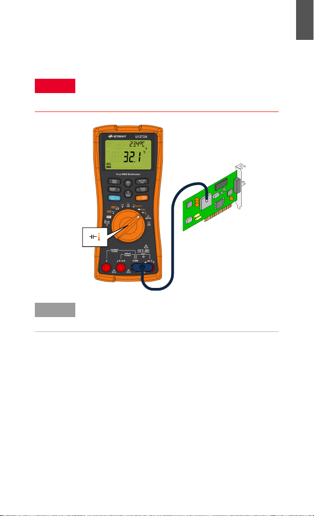
Temperature measurements
WARNING
NOTE
Set up your multimeter as shown in the figure
below to perform temperature measurements.
Do not connect the thermocouple to electrically live
circuits. Doing so will potentially cause fire or electric
shock.
The multimeter uses a type-K (defaul t setting)
temperature probe for measuring temperature.
ENGLISH
Keysight U1271A/U1272A Quick Start Guide 17
Page 18
ENGLISH
S
h
i
f
t
V
i
e
w
E
s
c
WARNING
AC
LOAD
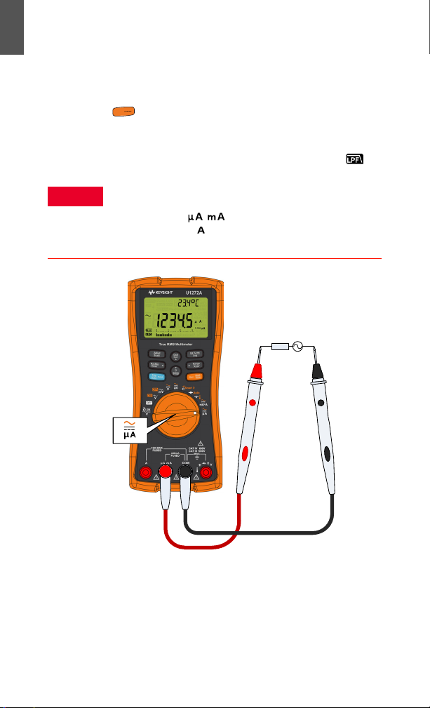
Current measurements
Set up your multimeter as shown in the figure
below to perform current measurements. Press
to switch between AC, DC, AC+DC, or %
scale current measurements. When measuring
DC current from a mixed signal in DC
measurement mode, ensure that the Filter ( ) is
enabled.
Always use the proper function, range, and terminals
for current measurements. Set the positive input
terminal to the terminal for currents below
440 mA, and the terminal for currents above
440 mA.
18 Keysight U1271A/U1272A Quick Start Guide
Page 19
Contacting Keysight
CAUTION
WARNING
CAT III
CAT IV
600 V
To obtain service, warranty or technical assistance, contact us at the
following phone numbers:
– United States Call Center: 800-829-4444
– Canada Call Center: 877-894-4414
– China Call Center: 800-810-0189
– Europe Call Center: 31-20-547-2111
– Japan Call Center: (81) 426-56-7832
For other countries, contact your country’s Keysight support
organization. A list of contact information for other countries is
available on the Keysight Website: www.keysight.com/find/assist
Safety Notices Safety Information
A CAUTION notice
denotes a hazard. It
calls attention to an
operating procedure,
practice, or the like
that, if not correctly
performed or adhered
to, could result in
damage to the product
or loss of important
data. Do not proceed
beyond a CAUTION
notice until the
indicated conditions
are fully understood
and met.
A WARNING notice
denotes a hazard. It
calls attention to an
operating procedure,
practice, or the like
that, if not correctly
performed or adhered
to, could result in
personal injury or
death. Do not proceed
beyond a WARNING
notice until the
indicated conditions
are fully understood
and met.
This meter is safety-certified in
compliance with EN/IEC 61010-1:2001,
ANSI/UL 61010-1:2004, and
CAN/CSA-C22.2 No.
61010-1-04. Use with standard or
compatible test probes.
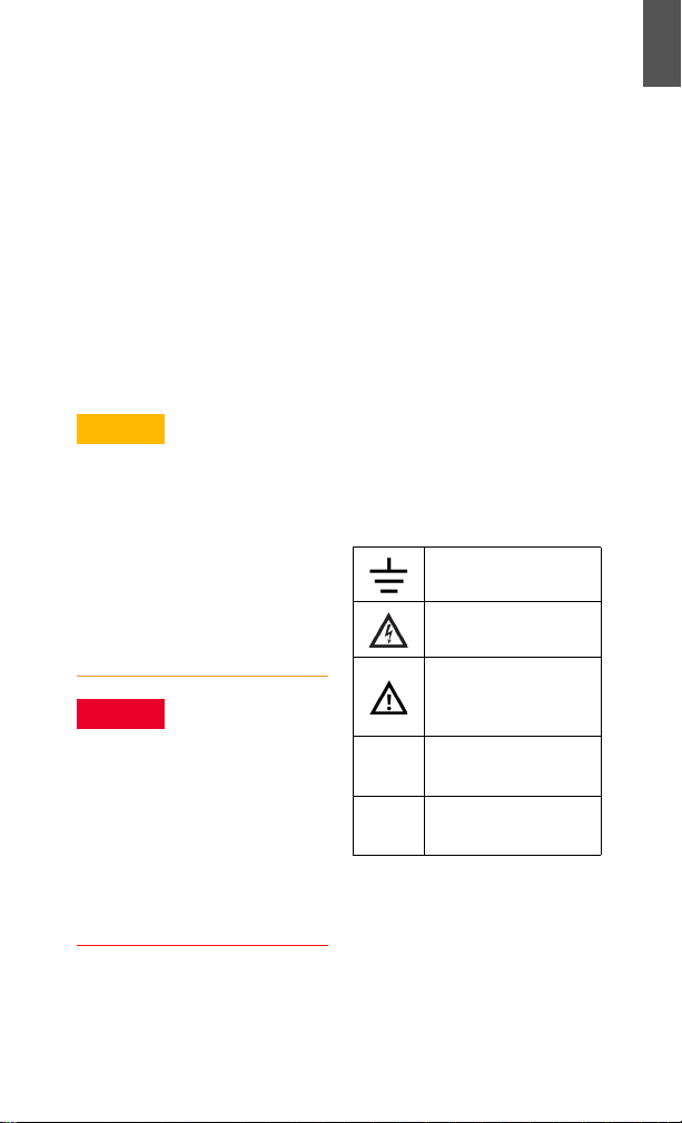
Safety Symbols
Earth (ground) terminal
Caution, risk of electric
shock
Caution, risk of danger
(refer to the instrument
manual for specific
Warning or Caution
information)
Category III 1000 V
overvoltage protection
Category IV 600 V
overvoltage protection
ENGLISH
For further safety information details, refer to the Keysight
U1271A/U1272A Handheld Digital Multimeter User’s Guide.
Keysight U1271A/U1272A Quick Start Guide 19
Page 20

ENGLISH
THIS PAGE HAS BEEN INTENTIONALLY LEFT BLANK.
20 Keysight U1271A/U1272A Quick Start Guide
Page 21

This information is subject to change
without notice. Always refer to the
Keysight website for the latest revision.
© Keysight Technologies 2010-2021
Edition 7, March 2021
Printed in Malaysia
U1271-90000
www.keysight.com
 Loading...