

Page 1

Keysight RP7900 Series
Regenerative Power System
This manual provides the documentation for the following
instruments: RP7951AT, RP7952AT, N6991A, RP7951A,
RP7952A, RP7953A, RP7961A, RP7962A, and RP7963A
Advanced
Service Guide
Page 2

Notices
CAUTION
WARNING
Copyright Notice
© Keysight Technologies 2019
No part of this manual may be repro-
duced in any form or by any means
(including electronic storage and
retrieval or translation into a foreign
language) without prior agreement and
written consent from Keysight Technologies as governed by United States and
international copyright laws.
Manual Part Number
RP7900-90000
Edition
Edition 1, July 11, 2019
Printed in:
Printed in Malaysia
Published by:
Keysight Technologies
Bayan Lepas Free Industrial Zone,
11900 Penang, Malaysia
Technology Licenses
The hardware and/or software
described in this document are furnished under a license and may be
used or copied only in accordance with
the terms of such license.
Declaration of Conformity
Declarations of Conformity for this
product and for other Keysight products may be downloaded from the
Web. Go to http://www.keysight.com/
go/conformity. You can then search by
product number to find the latest Declaration of Conformity.
U.S. Government Rights
The Software is “commercial computer
software,” as defined by Federal Acquisition Regulation (“FAR”) 2.101. Pursuant to FAR 12.212 and 27.405-3 and
Department of Defense FAR Supplement (“DFARS”) 227.7202, the U.S.
government acquires commercial computer software under the same terms
by which the software is customarily
provided to the public. Accordingly,
Keysight provides the Software to U.S.
government customers under its standard commercial license, which is
embodied in its End User License
Agreement (EULA), a copy of which can
be found at http://www.keysight.com/
find/sweula. The license set forth in the
EULA represents the exclusive authority
by which the U.S. government may use,
modify, distribute, or disclose the Software. The EULA and the license set
forth therein, does not require or permit, among other things, that Keysight:
(1) Furnish technical information
related to commercial computer software or commercial computer software
documentation that is not customarily
provided to the public; or (2) Relinquish
to, or otherwise provide, the government rights in excess of these rights
customarily provided to the public to
use, modify, reproduce, release, perform, display, or disclose commercial
computer software or commercial computer software documentation. No
additional government requirements
beyond those set forth in the EULA
shall apply, except to the extent that
those terms, rights, or licenses are
explicitly required from all providers of
commercial computer software pursuant to the FAR and the DFARS and are
set forth specifically in writing elsewhere in the EULA. Keysight shall be
under no obligation to update, revise or
otherwise modify the Software. With
respect to any technical data as
defined by FAR 2.101, pursuant to FAR
12.211 and 27.404.2 and DFARS
227.7102, the U.S. government
acquires no greater than Limited Rights
as defined in FAR 27.401 or DFAR
227.7103-5 (c), as applicable in any
technical data.
Warranty
THE MATERIAL CONTAINED IN THIS
DOCUMENT IS PROVIDED “AS IS,”
AND IS SUBJECT TO BEING
CHANGED, WITHOUT NOTICE, IN
FUTURE EDITIONS. FURTHER, TO THE
MAXIMUM EXTENT PERMITTED BY
APPLICABLE LAW, KEYSIGHT DISCLAIMS ALL WARRANTIES, EITHER
EXPRESS OR IMPLIED, WITH REGARD
TO THIS MANUAL AND ANY INFORMATION CONTAINED HEREIN, INCLUDING BUT NOT LIMITED TO THE
IMPLIED WARRANTIES OF MERCHANTABILITY AND FITNESS FOR A
PARTICULAR PURPOSE. KEYSIGHT
SHALL NOT BE LIABLE FOR ERRORS
OR FOR INCIDENTAL OR CONSEQUENTIAL DAMAGES IN CONNECTION
WITH THE FURNISHING, USE, OR
PERFORMANCE OF THIS DOCUMENT
OR OF ANY INFORMATION CONTAINED HEREIN. SHOULD KEYSIGHT
AND THE USER HAVE A SEPARATE
WRITTEN AGREEMENT WITH WARRANTY TERMS COVERING THE MATERIAL IN THIS DOCUMENT THAT
CONFLICT WITH THESE TERMS, THE
WARRANTY TERMS IN THE SEPARATE
AGREEMENT SHALL CONTROL.
Safety Information
A CAUTION notice denotes a hazard. It
calls attention to an operating procedure, practice, or the like that, if not
correctly performed or adhered to,
could result in damage to the product
or loss of important data. Do not proceed beyond a CAUTION notice until
the indicated conditions are fully
understood and met.
A WARNING notice denotes a hazard. It
calls attention to an operating procedure, practice, or the like that, if not
correctly performed or adhered to,
could result in personal injury or death.
Do not proceed beyond a WARNING
notice until the indicated conditions are
fully understood and met.
2 Keysight RP7900 Series Advanced Service Guide
Page 3

Safety Notices
WARNING
WARNING
The following general safety precautions must be observed during all phases of
operation of this instrument. Failure to comply with these precautions or with
specific warnings or instructions elsewhere in this manual violates safety
standards of design, manufacture, and intended use of the instrument. Keysight
Technologies assumes no liability of the customer’s failure to comply with the
requirements.
The equipment is for industrial use. Equipment operators are subject to all
applicable safety regulations. Along with the warning and safety notices in this
manual, all relevant safety, accident prevention, and environmental regulations
must also be followed. In particular, the operators of the equipment:
– Must be informed of the relevant safety requirements.
– Must have read and understood the operating manual before using the
– Must use the designated and recommended safety equipment.
General
Do not use this product in any manner not specified by the manufacturer.
The protective features of this product may be impaired if it is used in a
manner not specified in the operating instructions.
equipment.
Keysight RP7900 Series Advanced Service Guide 3
Environmental conditions
Never use the instrument outside of the specified environmental conditions
described in the Environmental Characteristics of the RP7900 Series
Operating and Service Guide.
Page 4

WARNING
Heavy weight
WARNING
WARNING
Danger to hands and feet. To avoid personal injury and damage to the
instrument, always use a sturdy cart or other suitable device to move the
instrument. Do not lift the instrument alone; always use two people to lift
the instrument.
SHOCK HAZARD - Ground the instrument
This product is provided with a protective earth terminal. To minimize shock
hazard, the instrument must be connected to the AC mains through a
grounded power cable, with the ground wire firmly connected to an
electrical ground (safety ground) at the power outlet. Any interruption of the
protective (grounding) conductor or disconnection of the protective earth
terminal will cause a potential shock hazard that could result in injury or
death.
Before applying power
Verify that all safety precautions are taken. All connections must be made
with the unit turned off, and must be performed by qualified personnel who
are aware of the hazards involved. Improper actions can cause fatal injury as
well as equipment damage. Note the instrument's external markings
described under Safety Symbols and Regulatory Markings.
4 Keysight RP7900 Series Advanced Service Guide
Page 5

WARNING
SHOCK HAZARD, LETHAL VOLTAGES
WARNING
WARNING
WARNING
WARNING
Many models generate voltages greater than 60 VDC, with some models
rated at 950 VDC! Ensure that all instrument connections, load wiring, and
load connections are either insulated or covered using the safety covers
provided, so that no accidental contact with lethal voltages can occur.
SHOCK HAZARD
Never touch cables or connections immediately after turning off the unit.
Depending on the model, lethal voltages can remain at the output terminals
for several seconds after turn-off. Verify that there is no dangerous voltage
on the output or sense terminals before touching them.
SHOCK HAZARD from external energy sources
Because the instrument can be used as a load to sink current, hazardous
voltages from an external energy source such as a battery may be present on
the output terminals even with the unit turned off. Provision must be made
to disconnect the external energy source before touching the output or
sense terminals.
Keysight RP7900 Series Advanced Service Guide 5
Do not operate in an explosive atmosphere
Do not operate the instrument in the presence of flammable gases or fumes.
Do not remove the instrument cover
Only qualified, service-trained personnel who are aware of the hazards
involved should remove instrument covers. Always d isconnect the power
cable and any external circuits before removing the instrument cover.
Page 6

WARNING
Do not modify the instrument
WARNING
WARNING
WARNING
Do not install substitute parts or perform any unauthorized modification to
the product. Return the product to a Keysight Sales and Service Office for
service and repair to ensure that safety features are maintained.
Fuses
The instrument contains an internal fuse, which is not customer accessible.
Cleaning
To prevent electric shock, always disconnect the AC mains before cleaning.
Use a dry cloth or one slightly dampened with water to clean the external
case parts. Do not use detergent or chemical solvents. Do not attempt to
clean internally.
In case of damage
Instruments that are not functioning correctly, appear damaged or defective
should be made inoperative and secured against unintended operation until
they can be repaired by qualified service personnel.
6 Keysight RP7900 Series Advanced Service Guide
Page 7
Safety Symbols and Regulatory Markings
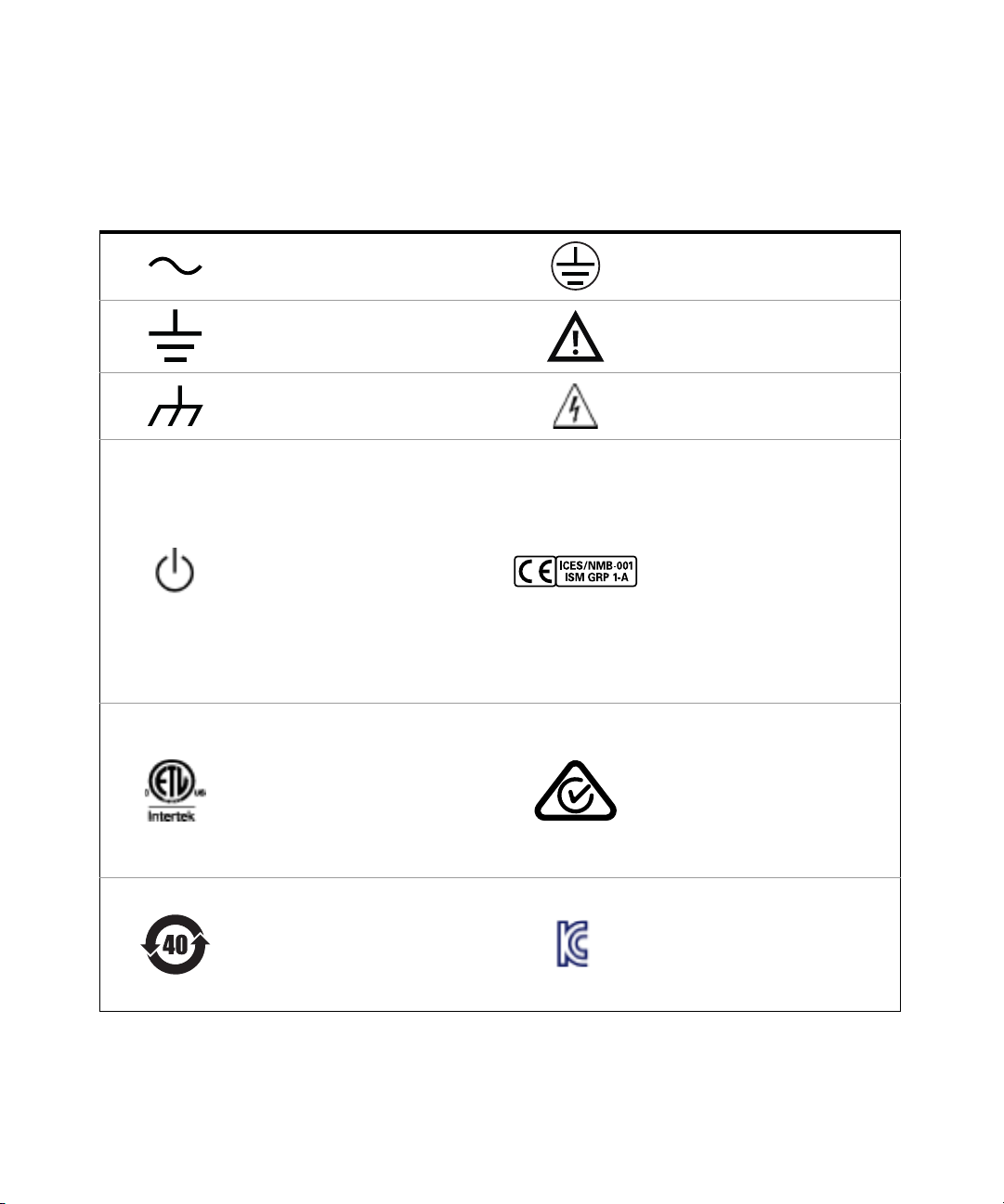
Alternating current (AC) Protective earth (ground) terminal
Earth (ground) terminal
Frame or chassis (ground) terminal Caution, risk of electric shock
Standby supply. Unit is not completely
disconnected from AC mains when
switch is off.
The ETL mark is a registered trademark
of Intertek. The text indicates product
compliance with the Canadian
Interference- Causing Equipment
Standard (ICES-001).
Caution, risk of danger (refer to this
manual for specific Warning or Caution
information)
The CE mark is a registered trademark
of the European Community. This CE
mark shows that the product complies
with all the relevant European Legal
Directives.
ICES/NMB-001 - This ISM device
complies with the Canadian ICES-001.
Cet appareil ISM est conforme a la
norme NMB-001 du Canada.
ISM GRP 1-A - This is an Industrial
Scientific and Medical (ISM) Group 1
Class A product.
This product is marked with the ACMA
RCM mark for compliance in Australia/
New Zealand. A copy of the
Manufacturer's Australia Declaration of
Conformity for this instrument can be
obtained by contacting your local
Keysight Technologies Sales
Representative.
This symbol indicates the time period
during which no hazardous or toxic
substance elements are expected to
leak or deteriorate during normal use.
Forty years is the expected useful life
of the product.
This symbol is a South Korean Class A
EMC Declaration. This is a Class A
instrument suitable for professional
use and in electromagnetic
environment outside of the home.
Keysight RP7900 Series Advanced Service Guide 7
Page 8

South Korean Class A EMC Declaration
Information to the user:
This instrument has been conformity assessed for used in business environments.
In a residential environment this equipment may caused radio interference.
This EMC statement applies to the equipment only for use in business
environment.
사 용 자 안 내 문
이 기 기 는 업 무 용 환 경 에 서 사 용 할 목 적 으 로 적 합 성 평 가 를 받 은 기 기 로 서 가 정
용 환 경 에 서 사 용 하 는 경 우 전 파 간 섭 의 우 려 가 있 습 니 다 .
사용자 안내문은 " 업무용 방송통신기자재 " 에만 적용한다 .
8 Keysight RP7900 Series Advanced Service Guide
Page 9
Waste Electrical and Electronic Equipment (WEEE) Directive
This instrument complies with the WEEE Directive marking requirement. This
affixed product label indicates that you must not discard this electrical or
electronic product in domestic household waste.
Product category:
With reference to the equipment types in the WEEE directive Annex 1, this
instrument is classified as a “Monitoring and Control Instrument” product.
The affixed product label is as shown below.
Do not dispose in domestic household waste.
To return this unwanted instrument, contact your nearest Keysight Service Center,
or visit http://about.keysight.com/en/companyinfo/environment/takeback.shtml
for more information.
Sales and Technical Support
To contact Keysight for sales and technical support, refer to the support links on
the following Keysight websites:
– www.keysight.com/find/RP7900
(product-specific information and support, software and
documentation updates)
– www.keysight.com/find/assist
(worldwide contact information for repair and service)
Keysight RP7900 Series Advanced Service Guide 9
Page 10

THIS PAGE HAS BEEN INTENTIONALLY LEFT BLANK.
10 Keysight RP7900 Series Advanced Service Guide
Page 11

Table of Contents
Safety Notices . . . . . . . . . . . . . . . . . . . . . . . . . . . . . . . . . . . . . . . . . . . . . .3
Safety Symbols and Regulatory Markings . . . . . . . . . . . . . . . . . . . . . . . .7
South Korean Class A EMC Declaration . . . . . . . . . . . . . . . . . . . . . . . . .8
Waste Electrical and Electronic Equipment (WEEE) Directive . . . . . . . .9
Product category: . . . . . . . . . . . . . . . . . . . . . . . . . . . . . . . . . . . . . . . .9
Sales and Technical Support . . . . . . . . . . . . . . . . . . . . . . . . . . . . . . . . . .9
1 Troubleshooting
Safety Precaution . . . . . . . . . . . . . . . . . . . . . . . . . . . . . . . . . . . . . . . . . .14
Before, During, and After Troubleshooting . . . . . . . . . . . . . . . . . . . . . .15
Introduction to the Titan HV (RP7900 Series) Architecture . . . . . . . . .16
Titan HV architecture: . . . . . . . . . . . . . . . . . . . . . . . . . . . . . . . . . . . .17
General Troubleshooting Information . . . . . . . . . . . . . . . . . . . . . . . . . .26
List of Error Codes . . . . . . . . . . . . . . . . . . . . . . . . . . . . . . . . . . . . . . . . .27
Hardware Troubleshooting Guide . . . . . . . . . . . . . . . . . . . . . . . . . . . . .31
Required equipment . . . . . . . . . . . . . . . . . . . . . . . . . . . . . . . . . . . . .31
Hardware trouble shooting procedure . . . . . . . . . . . . . . . . . . . . . . . 32
2Disassembly
Electrostatic Discharge (ESD) Precautions . . . . . . . . . . . . . . . . . . . . . .40
Disassembly Tools . . . . . . . . . . . . . . . . . . . . . . . . . . . . . . . . . . . . . . . . .41
Disassembly Tips . . . . . . . . . . . . . . . . . . . . . . . . . . . . . . . . . . . . . . . . . .42
Removing/Installing flat flexible cables (FFC) or ribbon cables . . . .42
Assembly procedures . . . . . . . . . . . . . . . . . . . . . . . . . . . . . . . . . . . . .42
Disassembly Procedures . . . . . . . . . . . . . . . . . . . . . . . . . . . . . . . . . . . .43
Removing the top chassis . . . . . . . . . . . . . . . . . . . . . . . . . . . . . . . . .43
Removing the PFC control board . . . . . . . . . . . . . . . . . . . . . . . . . . . 45
Removing the digital personality module PCA . . . . . . . . . . . . . . . . .48
Removing the isolation and isolation attic board (top and bottom) from
the chassis . . . . . . . . . . . . . . . . . . . . . . . . . . . . . . . . . . . . . . . . . . .52
Keysight RP7900 Series Advanced Service Guide 11
Page 12

Removing the regulation magnitcs PCA from the regulation PCA . 55
Removing the isolation partition, insulator regulation, and chassis
module . . . . . . . . . . . . . . . . . . . . . . . . . . . . . . . . . . . . . . . . . . . . . 56
Removing the output and back plane assembly . . . . . . . . . . . . . . . 59
Removing the bias bracket from the chassis . . . . . . . . . . . . . . . . . . 62
Removing the constellation and P600 assembly from the chassis . 63
Removing the GPIB board from the chassis . . . . . . . . . . . . . . . . . . . 65
Removing the IO board from the chassis . . . . . . . . . . . . . . . . . . . . . 66
Removing the front panel from the chassis . . . . . . . . . . . . . . . . . . . 67
Removing the front frame vent from the chassis . . . . . . . . . . . . . . . 70
Removing the fan bracket assembly from the chassis . . . . . . . . . . . 71
3Replaceable Parts
RP7900 Replaceable Parts List . . . . . . . . . . . . . . . . . . . . . . . . . . . . . . . 76
12 Keysight RP7900 Series Advanced Service Guide
Page 13

Keysight RP7900 Series Regenerative Power System
Advanced Service Guide
1 Troubleshooting
Safety Precaution 14
Before, During, and After Troubleshooting 15
Introduction to the Titan HV (RP7900 Series) Architecture 16
General Troubleshooting Information 26
List of Error Codes 27
Hardware Troubleshooting Guide 31
This chapter lists the possible errors and their description and discusses the
procedures for troubleshooting the Keysight RP7900 Series Regenerative Power
System.
13
Page 14

1 Troubleshooting
WARNING
CAUTION
Safety Precaution
A WARNING notice denotes a hazard. It calls attention to an operating
procedure, practice, or the like that, if not correctly performed or adhered to,
could result in personal injury or death. Do not proceed beyond a WARNING
notice until the indicated conditions are fully understood and met.
A CAUTION notice denotes a hazard. It calls attention to an operating
procedure, practice, or the like that, if not correctly performed or adhered to,
could result in damage to the product or loss of important data. Do not
proceed beyond a CAUTION notice until the indicated conditions are fully
understood and met.
Read the information in the “Safety Notices” on page 3 and the “Safety Symbols
and Regulatory Markings” on page 7 before proceeding with the rest of this
chapter.
Ensure that all safety precautions are observed during all phases of operation of
this instrument. Failure to comply with these precautions or with specific warnings
or instructions elsewhere in this manual or in the RP7900 Series Operating and
Service Guide violates safety standards of design, manufacture, and intended use
of the instrument. Keysight Technologies assumes no liability of the customer’s
failure to comply with the requirements.
This manual serves as a complement to the RP7900 Series Operating and Service
Guide. Only qualified, service-trained personnel who have read the Operating and
Service Guide prior to this should attempt the procedures listed in this manual.
14 Keysight RP7900 Series Advanced Service Guide
Page 15

Before, During, and After Troubleshooting
1 Before turning on the unit under test (UUT):
– Make sure all connections are done correctly.
– Connect the 3-phase power cord to the UUT before connecting the plug to
3-phase main power trunk.
2During test:
– DO NOT probe any area of the UUT as there is HIGH RAIL VOLTAGE present
while the UUT is powered ON.
– If you wish to measure any test points, always ensure that the DMM probes
stay on the measurement area before powering on the UUT.
3 After test:
– Turn off the UUT and all other testing equipment.
– Unplug the 3-phase power cord immediately.
– DO NOT touch any location of the UUT as the HIGH RAIL VOLTAGE is slowly
discharging (the RAIL LED is RED).
– Wait 5 minutes or until the RAIL LED is OFF before performing any
disassembly procedure.
Troubleshooting 1
Keysight RP7900 Series Advanced Service Guide 15
Page 16

1 Troubleshooting
Introduction to the Titan HV (RP7900 Series) Architecture
Listed below are the Titan HV models (RP7900 Series):
– RP7951AT, RP7952AT, N6991AT
– RP7951A, RP7952A, RP7953A: Using AC input 208 Vrms
– RP7961A, RP7962A, RP7963A: Using AC input 400 Vrms
Specification RP7951A/RP7961A RP7952A/RP7962A RP7953A/RP7963A
DC ratings
Voltage source:
Current source and sink:
Power:
A Titan HV unit consists of:
– 3-phase AC/DC front end
– DC/DC isolation stage
– Non-isolated DC/DC regulation stage
– Control board and digital personality module (DPM)
[1]
: Using AC input 208 Vrms
0 to 500 V
0 to ±20 A
5 kW
0 to 500 V
0 to ±40 A
10 kW
0 to 950 V
0 to ±20 A
10 kW
– Output board
–Bias board
– Customer interface board (P600 and carrier)
[1] Limited distirbution/customers only. Not available for sale to the public on www.keysight.com.
16 Keysight RP7900 Series Advanced Service Guide
Page 17
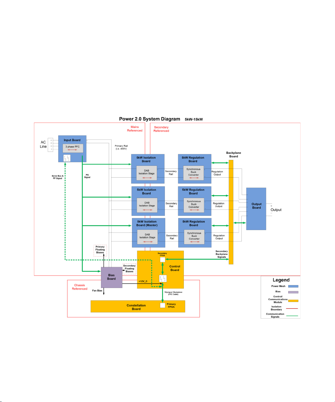
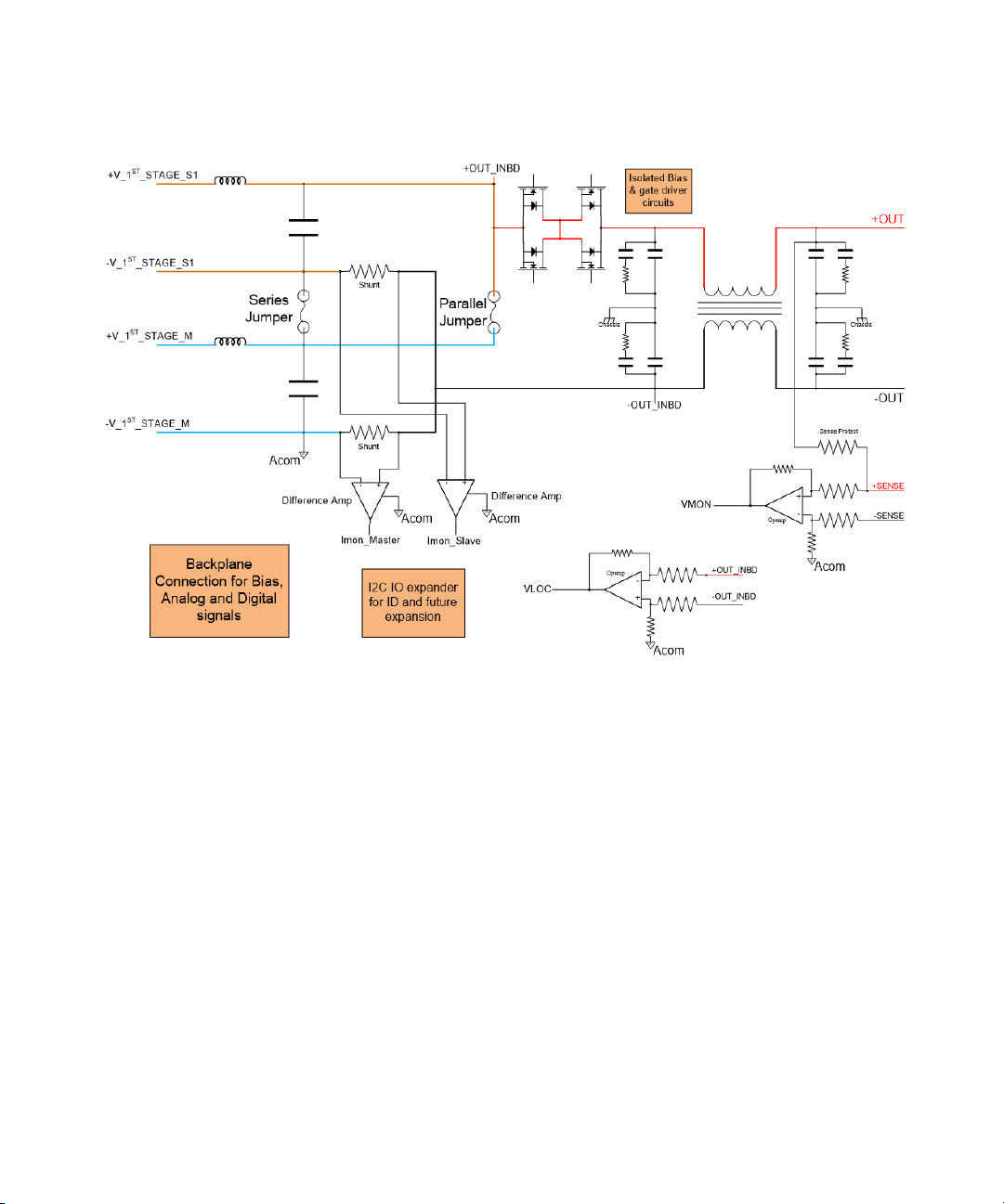
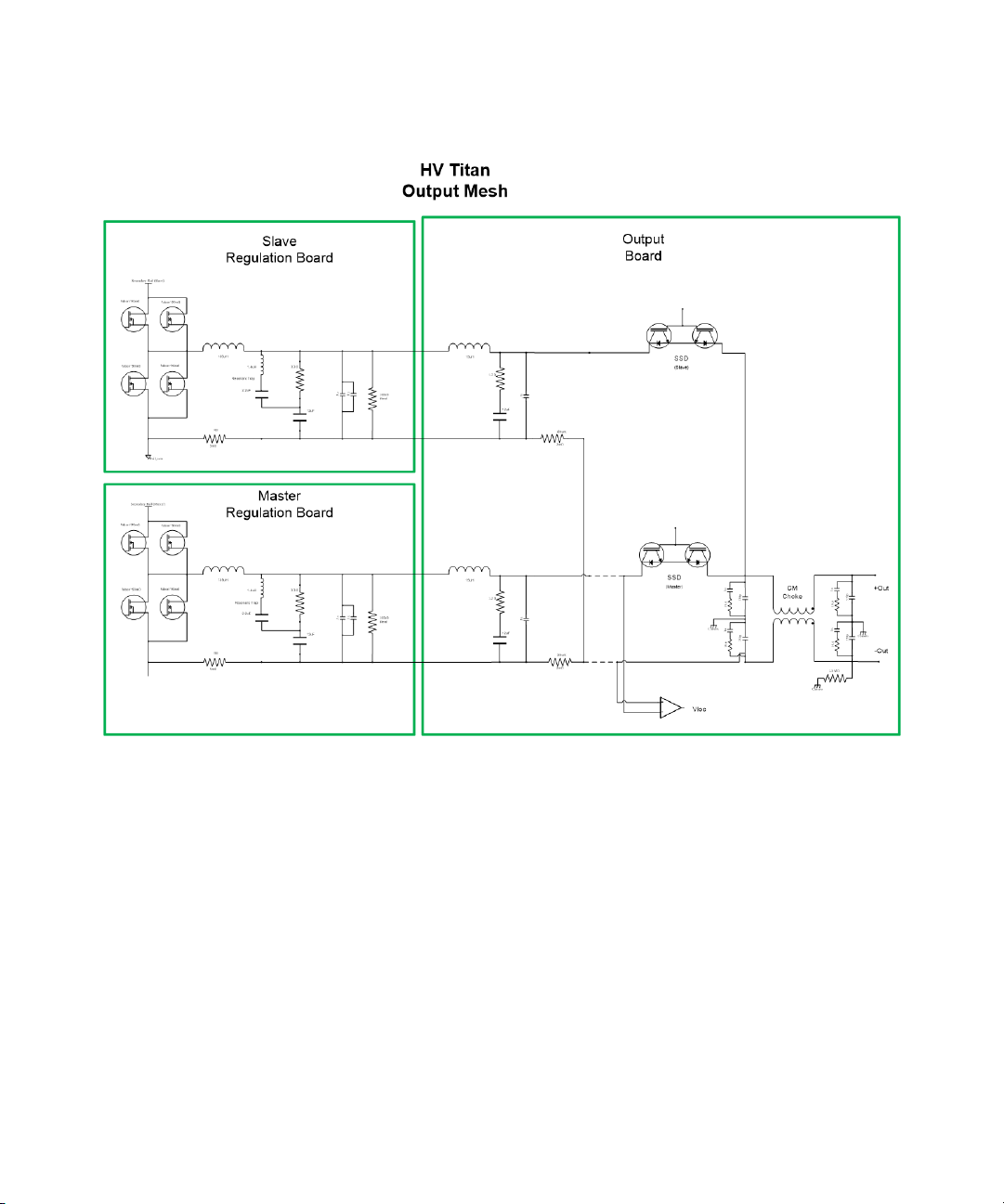
Titan HV architecture:
Shown below is the block diagram for a Titan HV unit.
– Titan HV 5 kW models (RP7951A/RP7961A): One pair of isolation board and
regulation board.
– Titan HV 10 kW models (RP7952A/RP7962A/RP7953A/RP7963A): Two pairs of
isolation board and regulation board.
Troubleshooting 1
Keysight RP7900 Series Advanced Service Guide 17
Page 18
1 Troubleshooting
– Power Good (PG) signal: If the PG signal is not detected, the input board can
– Power Fault (PF) signal: If the PF signal is detected, the input board asserts
shut down the isolation boards and bias board and create a “Channel Fail”
error code at display.
this signal when it determines if the output power should be inhibited to
preserve rail charge in the event of a line fault.
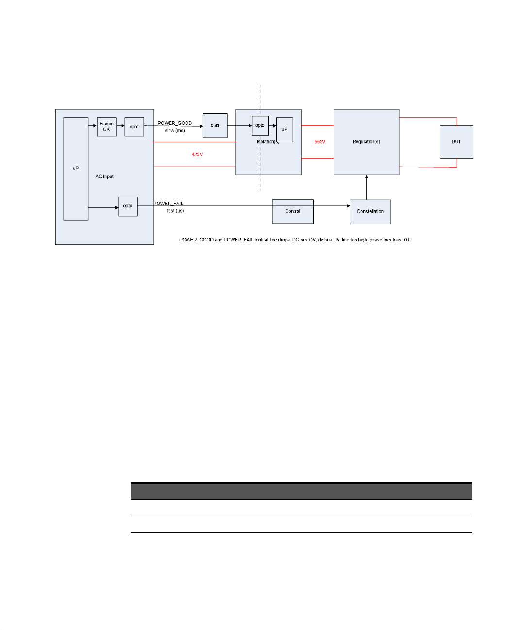
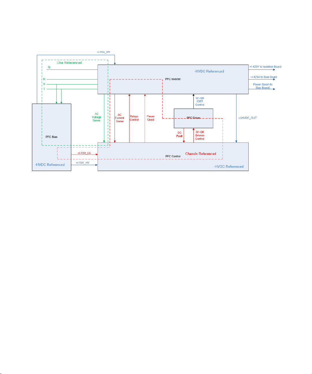
3-phase AC/DC front end:
The 3-phase AC/DC front end consists of the Power Factor Correction (PFC)
bias-control board, PFC driver board, and PFC inverter board. Its main function is
to convert the 3-phase AC input voltage to the require DC voltage as shown in
table below.
The AC front end will assert a PF signal to the secondary FPGA when the line
conditions are severe enough that the output power should be restricted or if the
rail voltage dips below a ‘power fault’ level. The purpose of this signal is to quickly
notify the regulation board to temporarily latch its output in the event of a brief
line drop out.
Model AC 3-phase input DC output
RP7951A, RP7952A, RP7953A 208 Vrms 425 Vdc
RP7961A, RP7962A, RP7963A 400 Vrms 980 Vdc
18 Keysight RP7900 Series Advanced Service Guide
Page 19
Troubleshooting 1
PFC inverter board operation
– The inverter boards consists of fuses, relay, big relay, and hall current sensors.
– The AC 3-phase input will go through the fuses. By turning on the bias, the AC
input will go through a small relay with a resistor path in order to have a soft
charge on the capacitor in the driver board. After that, the big relay will be
turned on when you hear the second clicking sound.
– The current passes through the hall sensor into the choke followed by the IGBT
and output capacitors.
PFC driver board operation
– The PFC driver boards consists of photo-detectors and big capacitors. The
gate driver output is influenced by signals from the photo-detector circuitry.
During normal operation, if the supply voltage is above the UVLO threshold,
the output of the photo-detector will drive the IGBTs of the output stage.
Keysight RP7900 Series Advanced Service Guide 19
Page 20

1 Troubleshooting
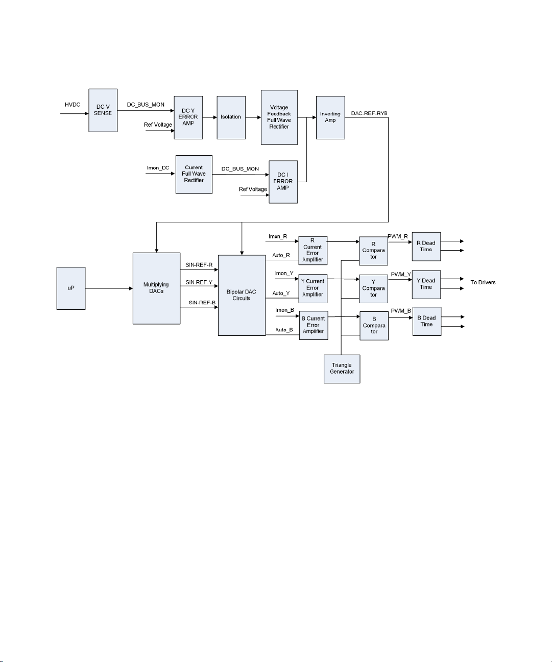
PFC bias control board operation
– The PFC bias control board consists of AC/DC current sensing, instantaneous
– The main purpose of the PFC control board is to provide the protection when
– The DC bus voltage monitors the output capacitor voltage. The center tap
– The function of the dead time circuit is to make sure that the gates will not be
– The triangle wave generator function acts as a reference signal, which
– The IPEAK_fault signal (peak current latch signal) will go into the inhibit logic
current protection, IGBT DESAT and PEAK current latch circuitry, AC/ DC
voltage sensing circuitry, current control loop, DC voltage error amplifier, and
dead circuitry.
abnormalities are detected on the peak current and to control and adjust the
DC output voltage.
monitors voltage across one capacitor whereas the DC bus monitors voltage
across the output cap. The main function of the center tap sensing is to ensure
that the voltage across is balanced.
turned on at the same time. It allows certain delays to prevent a short circuit.
compares the IMON signal, which eventually determines the PWM gate duty
cycle. This is a triangle waveform with a frequency of 33 kHz.
circuitry. In normal mode, IPEAK_latched and OC_latched must always stay
high whereas the Inhibit_R,Y,B depends on the Inverter_ON_R,Y,B to decide
whether it needs to turn the gate drive on or off. If the Inhibit_R,Y,B signal goes
low, the microprocessor will shut down the gate immediately.
20 Keysight RP7900 Series Advanced Service Guide
Page 21
Troubleshooting 1
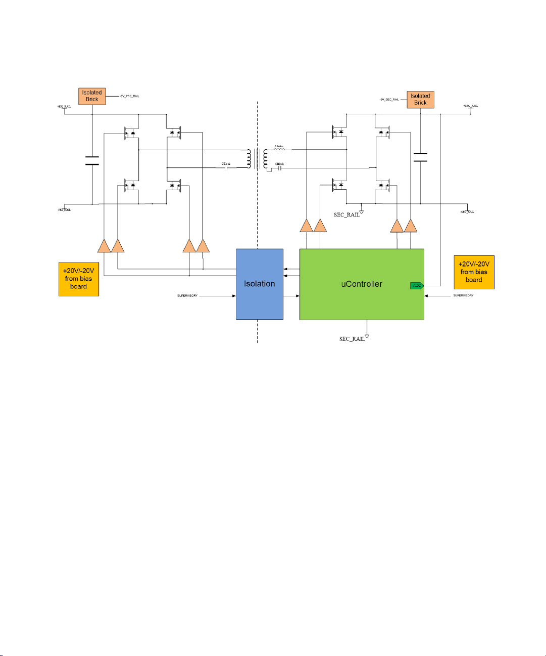
Isolation and isolation attic board operation
– The isolation board consists of a H bridge circuitry that can step up and step
down the voltage to the required voltage level. Its main function is to provide
the isolation between the primary and secondary circuits. It receives the DC
voltage from the AC front end and then adjusts the voltage level to 565 V. The
isolation attic board consist of a transformer and over-current protection
circuitry.
– The isolation board protects itself from ‘live’ conditions, such as local over
temperature (OT) and rail over voltage (OV) or low voltage (LV). The source of
a rail OV/LV will either be an issue with its input, an internal malfunction, or a
regulation board malfunction.
Keysight RP7900 Series Advanced Service Guide 21
Page 22
1 Troubleshooting
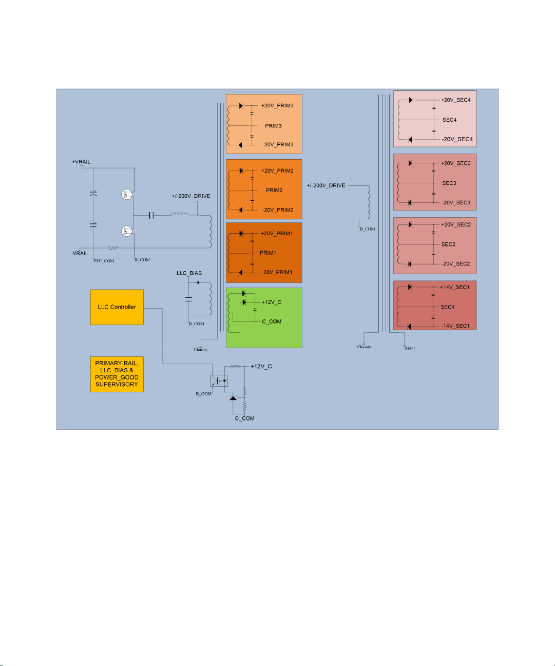
Bias board operation
– The bias board is made of a half-bridge LLC with two flying shielded
transformers.
– It receives the PG signal and outputs voltage (425 V or 980 V) from the AC
front end, steps down the voltage, and provides the bias voltages to the
respective modules.
– It communicates using the PG signal from the front-end.
Provides ±23 V to the isolation board
Provides ±23 V to the regulation board
Provides +12 V to the chassis fan
Provides ±15 V to the control board
22 Keysight RP7900 Series Advanced Service Guide
Page 23
Troubleshooting 1
Output board operation
– The output board contains an accuracy shunt resistor, a common mode choke,
filtering circuitry, and a solid state output disconnect circuit up to 40 A.
– Feedback circuitry such as V
accuracy of the voltage or current. The output board has different
configuration, such as parallel or series — it depends on the unit model
whether it is a high voltage or high current model. The output board will
provide the second level of filtering to the output.
Keysight RP7900 Series Advanced Service Guide 23
mon
and I
will be used to fine tune the
Mon
Page 24
1 Troubleshooting
MASTER/SLAVE board operation
– The master slave circuitry allows communication between the units. This
allows the user to talk with only the master when paralleling units.
24 Keysight RP7900 Series Advanced Service Guide
Page 25
Troubleshooting 1
Digital personality module (DPM) operation
– The DPM modules consists of the FPGA, AUX DAC, and AUX ADC, which main
purpose is to process the signal received. The calibration files will be stored in
the DPM.
P600 and constellation boards operation
– The P600 is the processor board, which will store the firmware.
– The constellation board is the interface board, which is equipped with other
communication peripherals such as the USB port, LAN port, and GPIB ports.
Keysight RP7900 Series Advanced Service Guide 25
Page 26

1 Troubleshooting
NOTE
General Troubleshooting Information
Refer to the RP7900 Series Operating and Service Guide for more details on the
recommended ETE information.
Model Firmware
RP7951AT, RP7952AT, N6991AT B_01_02_730 Available
RP7951, RP7952A, RP7953A , RP7961A,
RP7962A, RP7963A
– To obtain the latest firmware for the RP795xA and RP796xA series, go to
www.keysight.com/find/RPS2firmware.
– For firmware updates that are available only for Keysight’s Internal Support, go
to the RP7900 Series SharePoint folder for more information, or contact your
respective product helpdesk representative.
You will need to use the Firmware Update Utility to install the latest firmware for
your instrument. Refer to the Firmware Update Utility Instructions for more
information on how to update your instrument’s firmware.
The availability of INTERNAL ONLY firmware updates are depend on the product
requirements, and may be applicable to selected models only.
For more information, see www.keysight.com/find/RP7900.
Refer to the “List of Error Codes” on page 27 before attempting the hardware
troubleshooting procedure.
B_01_02_749 Not available
Keysight SD1000A SDS (safety
disconnect system) port functionality
26 Keysight RP7900 Series Advanced Service Guide
Page 27

List of Error Codes
The front-panel ERR annunciator turns on when there are one or more errors in
the error queue.
The front panel report errors from all I/O sessions and the global error queue. To
read the error queue from the front panel, press the [ERROR] key or alternatively,
send the
one error from the queue.
Error
Description Potential remedy
code
No error
0
This is the response to the ERR? query when there are no errors.
Calibration state is off
101
Calibration is not enabled. The instrument will not accept calibration commands.
Calibration password is incorrect
102
The calibration password is incorrect.
Calibration is inhibited by switch setting
103
Calibration mode is locked out by the calibration switch.
Bad sequence of calibration commands
104
Calibration commands have not been entered in the proper sequence.
Unexpected output current
105
The measured output current is outside the acceptable range.
Zero measurement out of range error
106
The “zero” measurement value is outside the acceptable range.
Programming cal constants out of range
107
The programmed calibration constant is outside the acceptable range.
Measurement cal constants out of range
108
The measurement calibration constant is outside the acceptable range.
Over voltage cal constants out of range
109
The over voltage calibration constant is outside the acceptable range.
Troubleshooting 1
SYSTem:ERRoR? command from the remote interface to read and clear
N/A
Check the CAL switch position
Reset the calibration password
Check the CAL switch position
Refer to the Calibration
procedure in the Operating and
Service Guide
Refer to the Calibration
procedure in the Operating and
Service Guide and the “Hardware
Troubleshooting Guide” on
page 31.
Keysight RP7900 Series Advanced Service Guide 27
Page 28

1 Troubleshooting
Error
Description Potential remedy
code
Wrong V+I
110
The instrument was unable to set the correct voltage or current value.
Wrong status
114
An incorrect status function has been reported.
Refer to the “Hardware
Troubleshooting Guide” on
page 31.
Locked out by internal switch setting
116
This function has been locked out by an internal switch.
Calibration error
117
A calibration error has occurred. Do not save calibration constants. Try
re-calibrating the unit.
Hard ware error channel <1>
200
A hardware error has occurred on the output.
Invalid configuration
201
An invalid parallel or SDS configuration is not allowed.
Self-test fail
202
A self test failure has occurred.
Compatibility function not implemented
203
The requested compatibility function is not available.
NVRAM checksum error
204
A checksum error has occurred in the instrument’s nonvolatile random access
memory.
NVRAM full
205
The nonvolatile random access memory of the instrument is full.
File not found
206
The internal calibration file or the internal channel attribute file was not found in
NVRAM.
Refer to the Operating and
Service Guide
Refer to the Calibration
procedure in the Operating and
Service Guide
Refer to the “Hardware
Troubleshooting Guide” on
page 31.
Check hardware model number
and firmware revision
Refer to the “Hardware
Troubleshooting Guide” on
page 31.
Check firmware revision
Check the P600 and constellation
flash memory or EEPROM
Check the DPM
Cal file version error
207
The calibration file was written or read using old firmware. The firmware must be
updated.
Running backup firmware
208
The instrument is presently running the backup (previous) version of the firmware.
Update the firmware revision
Check the P600 firmware
programming
28 Keysight RP7900 Series Advanced Service Guide
Page 29

Error
Description Potential remedy
code
Frame NVRAM error
210
A non-volatile RAM error has occurred in the instrument.
State file not loaded
212
A previously saved output state file has failed to load.
Troubleshooting 1
Check the P600 and constellation
flash memory or EEPROM
Line frequency error
214
A discrepancy has occurred between the line frequency and the line frequency
setting.
Hard ware failure
215
A hardware failure has occurred on the power supply
Option not installed
302
The option that is programmed by this command is not installed.
There is not a valid acquisition to fetch from
303
There is no valid data in the measurement buffer.
Volt and curr in incompatible transient modes
304
Voltage and current cannot be in Step and List mode at the same time.
A triggered value is on a d ifferent range
305
A triggered value is on a different range than the one that is presently set.
Too many list points
306
Too many list points have been specified.
List lengths are not equivalent
307
One or more lists are not the same length.
This setting cannot be changed while transient trigger is initiated
308
Setting cannot be changed while the instrument is waiting for or executing a trigger
sequence.
Cannot initiate voltage and current in fixed mode
309
Cannot initiate transient generator. Either the voltage or current function is set to
Fixed mode.
Check the AC line frequency
setting
Refer to the “Hardware
Troubleshooting Guide” on
page 31.
Install the required option
Refer to the Operating and
Service Guide
The command is not supported by this model
310
This instrument either does not have the hardware capability or the options
required to support this command.
Keysight RP7900 Series Advanced Service Guide 29
Page 30

1 Troubleshooting
Error
Description Potential remedy
code
Settings conflict error
315
A data element could not be programmed because of the present instrument state.
Mass storage error
316
The mass storage memory has been exceeded.
Invalid format
317
An invalid data format was found in the command string.
Firmware update error
320
This may be due to the instrument hardware not being able to support the firmware
version.
Inconsistent arb settings
324
The arb settings are inconsistent; most likely a mismatch in the arb lengths.
Initiated with no sense function enabled
327
A measurement has been initiated without specifying the
measurement(sense)function.
Too many measurement points
328
Too many measurement points have been specified.
Illegal parameter value
331
The parameter value is out of range or does not exist.
Master/slave error
332
An error has occurred in the master/slave configuration
Safety Disconnect error
333
An error has occurred in the SDS unit.
Refer to the Operating and
Service Guide
Check the hardware revision or
firmware programming setup
Refer to the Operating and
Service Guide
Check the master/slave
connection or the hardware
Check the SDS connection or the
hardware
30 Keysight RP7900 Series Advanced Service Guide
Page 31

Hardware Troubleshooting Guide
Required equipment
You will need the equipment listed below to perform the hardware
troubleshooting.
– DC electronic load: EA-EL 9750-75HP or Chroma 63206A-1200-240A or
equivalent
– Digital multimeter
– Keysight high performance Infiniium oscilloscope
–Current probe
– Differential probe
– Guild-line shunt
– DC power supply
– Cables and connectors
Troubleshooting 1
Keysight RP7900 Series Advanced Service Guide 31
Page 32

1 Troubleshooting
Hardware trouble shooting procedure
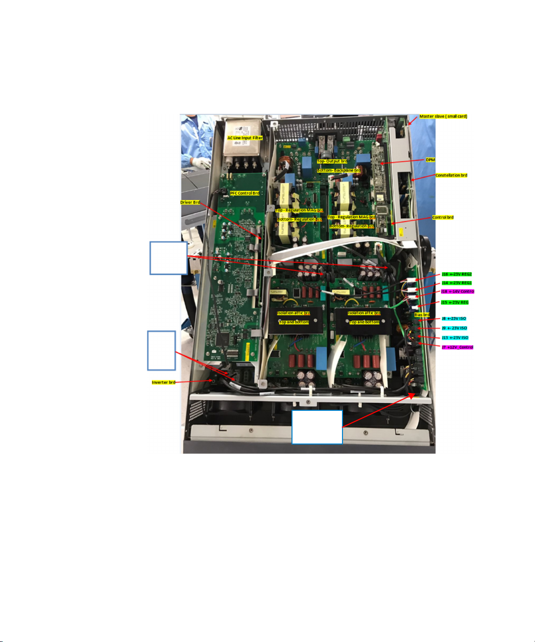
1 Visually inspect all the LED indicators as shown below:
Figure 1-1 Location of the LED indicators
32 Keysight RP7900 Series Advanced Service Guide
Page 33

Troubleshooting 1
G
C
A
Figure 1-2 Close-up location of DPM and constellation board LED
indicators
A Constellation board/P600 board LED
– Yellow LED flashing indicates that the firmware programming is done
properly and that the unit is booted up properly.
B PFC microcontroller LED
– There are two LEDs on the PFC microcontroller board, one red and one
green.
– Red LED off and green LED flashing constantly indicates that the
processor is running and everything is operating normally (i.e. the PFC
module is programmed properly).
– Solid red LED and green LED flashing constantly indicates that a
self-test error is being annunciated.
– Red LED flashing and green LED off indicates that a fault code is being
annunciated.
CDPM processor LED
– Green LED indicates that the unit has booted up properly.
DAC module rail LED
– Red LED indicates that there is rail voltage present.
Keysight RP7900 Series Advanced Service Guide 33
Page 34

1 Troubleshooting
2 Inspect all the flex cables and AWG cables connection and verify that they are
3 Measure the PFC output and ensure that the reading is 425 V for the 3-phase,
4 Make sure there is a 425 V (or 980 V, depending on the model) and a 10 V
E Isolation microcontroller LED
– Green LED flashing indicates that everything is operating normally.
– Solid green LED on indicates a soft start.
– Solid red LED indicates that a microcontroller error has occurred.
F Isolation board rail voltage LED
– Red LED indicates that 425 V (or 980 V, depending on the model) goes
into the isolation board.
G Regulation board rail voltage LED
– Red LED indicates that 565 V goes into the regulation board.
HBias board LED
– Red LED indicates that 425 V (or 980 V, depending on the model) and
the Power Good (PG) signal goes into the bias board.
correct. Make sure no connector pins are bent when the boards are installed to
the backplane.
208 V models or 980 V for the 3-phase, 480 V models.
Power Good (PG) signal going into the bias board. The bias board powers the
remaining boards.
5 Measure the isolation board output. Ensure that the reading is 565 V.
6 Verify that all biasing voltage from bias boards are correct. Refer to Figure 1-4
and Figure 1-5 for the biasing voltage test point locations and values.
7 Isolate the defective board(s) by disconnecting the cables connecting the
defective board(s) to the other boards.
– Disconnect the cable from the AC output to the isolation board to verify
that the AC board is functioning properly.
– Disconnect the cable connecting the isolation board to the regulation board
to verify that the isolation is good.
– Disconnect the cable from the regulation board to the output board to
verify that the regulation is good.
34 Keysight RP7900 Series Advanced Service Guide
Page 35

Troubleshooting 1
– For the control board, measure the V
mon
loc
, and I
signals that goes
mon
, V
into the board and verify that the values are accurate. Send the following
SCPI commands via the remote interface:
DIAG:MEAS:VOLT:LOC? – measures the local voltage from the aux ADC
DIAG:MEAS:AUX:CURR? - measures the current from the aux ADC
DIAG:MEAS:AUX:POWER? - measures the power from the aux ADC
DIAG:MEAS:MAIN:POW:LOC? - measures the local power from the main ADC
SCPI Command
DIAG:MEAS:VOLT:LOC?
Expected return value
21.45 V 499.72 V
[a]
Expected return value
DIAG:MEAS:AUX:CURR? 1.00 A 8.007 A
DIAG:MEAS:AUX:POWER? 20.11 W 4003.14 W
DIAG:MEAS:MAIN:POW:L
OC?
[a] Instrument setting - Voltage: 20 V, Current: 1 A
[b] Instrument setting - Voltage: 500 V, Current: 8 A
0.0806 W 16.013 W
8 Refer to the troubleshooting flow chart in Figure 1-3 for further details.
[b]
Keysight RP7900 Series Advanced Service Guide 35
Page 36

1 Troubleshooting
START
Set t he U UT vo ltage to 20 V
Measure d 20 V
at UUT output?
• Check the current accuracy with a load
or with the output terminal shorted.
• If it is a perfor mance is sue, pro ceed to
re-calibrate and re-verify.
Any error
message?
NO YES
PFC red LED
indicator on?
Isolation red LED
indicator on or rail
volta ge pr esent ?
Measure
the isolation circui t.
Is it 565 V?
Is t he re gulat ion rail
voltage indicator on?
NO
YES
YES
YES
• PF: Verify the incoming power fault channel. If the verification fails,
check the biasing voltage to the PCA. The MOSFET may be shorted.
Swap the PFC module.
• OT: Some components may be shorted or if there is a faulty sensor.
• OC: The regulation MOSFE T may be shorted. Swap the regulation
board.
• Self-test error: Verify if there are any incompatible firmware in any
of the modules.
• Check the PFC microcontroller LED.
• Check the PFC self-test LED sequence.
• Swap the PFC module.
YES
NO
• Check t he ca ble co nnecti ng to th e PFC.
• Check t he P FC ra il voltag e an d PG sign al.
• Swap the PFC module.
NO
• Check t hat the bias ing v olta ge (± 23 ~ ±24 V) g oes i nto the isol ation
primary and secondary circuit.
• Check that the microcontroller has been programmed with the
correct firmware.
• The MOSFET on the isolation board may be shorted. Swap the
isolation b oard.
NO
• Check t he ca ble co nnecti ng to th e iso lation.
• Check that the biasing voltage (±23 ~ ±24 V) goes into the
regulation board.
NO
Measure
the regulation output.
Is it 20 V?
YES
• Check the ILmon signal on the regulation board.
• The MOSFET on the regulation board may be shorted. Swap the
regulation board and the magnetic board.
NO
Verify that the
output board is producing
20 V at the bus bar .
YES
• Check the Vmon, Imon, and Vloc signal on the output board.
• Check i f a ny IG BTS ar e s horte d on t he o utp ut boa rd.
• Swap the output board.
NO
Verify that the
con tro l bo ar d V mon a nd
Imon signals are good.
YES
• Check that the biasing voltage (±24 V) goes into the control board.
• Check t he back plan e con nect ors.
• Check the FFC cable connecting to the control board.
• Swap the control board.
NO
Swap the DPM
YES
END
Figure 1-3 Hardware troubleshooting flow chart
36 Keysight RP7900 Series Advanced Service Guide
Page 37
Troubleshooting 1
Isolation
Brd Output
565Vdc
PFC AC
Output
425Vdc
425V and 10V
PG goes into
the Bias Brd
RP7951A, RP7952A, RP7953A, RP 7951AT, RP7952AT, N6991A
(3-phase, 208 V models)
Figure 1-4 Bias voltage test points for 3-phase, 208 V models
Keysight RP7900 Series Advanced Service Guide 37
Page 38

1 Troubleshooting
Isolation
Brd Output
565Vdc
PFC AC Output
980Vdc
980V and 10V
PG goes into
the Bias Brd
RP7961A, RP7962A, RP7963A (3-phase, 480 V models)
Figure 1-5 Bias vol tage test points for 3-phase, 480 V models
38 Keysight RP7900 Series Advanced Service Guide
Page 39

Keysight RP7900 Series Regenerative Power System
WARNING
Advanced Service Guide
2 Disassembly
Electrostatic Discharge (ESD) Precautions 40
Disassembly Tools 41
Disassembly Tips 42
Disassembly Procedures 43
This chapter discusses the disassembly procedures for troubleshooting and
repairing the Keysight RP7900 Series Regenerative Power System.
SHOCK HAZARD. Only qualified, service-trained personnel who are aware of
the hazards involved should remove instrument covers. Always disconnect
the power cable and any external circuits before removing the instrument
cover.
39
Page 40

2 Disassembly
Electrostatic Discharge (ESD) Precautions
Almost all electrical components can be damaged by electrostatic discharge
(ESD) during handling. Component damage can occur at electrostatic discharge
voltages as low as 50 volts. The following guidelines will help prevent ESD
damage when servicing the instrument or any electronic device.
– Disassemble instruments only in a static-free work area.
– Use a conductive work area to reduce static charges.
– Use a conductive wrist strap to reduce static accumulation.
– Minimize handling.
– Keep replacement parts in original static-free packaging.
– Remove all plastic, foam, vinyl, paper, and other static-generating materials
from the immediate work area.
40 Keysight RP7900 Series Advanced Service Guide
Page 41

Disassembly Tools
Table 2-1 Disassembly tools
Tool Use
T10 Torx driver All disassembles
T20 Torx driver Removing the output and back plane assembly
Flat blade driver Removing the fan bracket assembly from the chassis
7 mm Hex driver Removing the output and back plane assembly
8 mm Hex driver Removing the PFC control board
9/32 Hex driver Removing the GPIB board from the chassis
Disassembly 2
Keysight RP7900 Series Advanced Service Guide 41
Page 42

2 Disassembly
Disassembly Tips
Removing/Installing flat flexible cables (FFC) or ribbon cables
– Note the position of the conductive side of the cable for re-installation.
– To remove the FFC cable, gently lift up on the tabs located on the short ends of
the plastic connector until the cable is released. Remove the cable.
– To install the FFC cable, insert the cable into the slot in the connector. Using a
small screwdriver or your fingers, apply gentle, even pressure to the tabs until
the connector clicks and locks the cable into place. After installation, check
the cable to ensure the cable is straight and securely aligned within the
connector.
Assembly procedures
To assemble the instrument, reverse the procedures described in the
“Disassembly Procedures” on page 43.
42 Keysight RP7900 Series Advanced Service Guide
Page 43

Disassembly Procedures
Removing the top chassis
1 First, remove all cables, wires, or power cord that are connected to the
instrument before performing any disassembly.
2 Remove the 7 screws (0515-1946) on the top chassis of the instrument.
Disassembly 2
3 Next, remove the 3 screws (0515-0430) at the rear panel of the instrument.
Keysight RP7900 Series Advanced Service Guide 43
Page 44

2 Disassembly
NOTE
4 Then, remove the 10 screws (0515-1946) on both sides of the instrument as
shown below.
5 Gently remove the top chassis cover (5003-2346).
Ensure that a proper insulator is installed on the top cover. If the existing
insulator is damaged or worn out, please replace the existing insulator with a
new insulator (5188-9218).
44 Keysight RP7900 Series Advanced Service Guide
Page 45

Removing the PFC control board
1 First, remove all the cables that are connected to the PFC control board.
Disassembly 2
2 Next, remove the 2 screws (0515-0430) shown below.
Keysight RP7900 Series Advanced Service Guide 45
Page 46

2 Disassembly
3 Then, unsecure the 2 screws (0515-0430) shown below from the chassis.
4 Use an 8 mm Hex driver to remove the nut-hex (0535-0077) and then remove
the flat washer lock (2190-0629).
46 Keysight RP7900 Series Advanced Service Guide
Page 47

Disassembly 2
5 Flip the instrument to its bottom to remove the 5 screws (0515-1946) shown
below.
6 Finally, pull out the PFC control board from the chassis.
Keysight RP7900 Series Advanced Service Guide 47
Page 48

2 Disassembly
Removing the digital personality module PCA
1 First, gently unlock the connector pin and pull out the digital personality
module PCA (5067-5271) from its casing.
2 Next, remove the screw on the digital personality module PCA bracket.
48 Keysight RP7900 Series Advanced Service Guide
Page 49

Disassembly 2
3 Then, remove the screw securing the control PCA to the constellation bracket.
4 Next, remove the bias control cable.
Keysight RP7900 Series Advanced Service Guide 49
Page 50

2 Disassembly
5 Then, remove the constellation FFC cable at the back of the digital personality
module PCA.
6 Finally, remove the control insulator from the constellation bracket.
50 Keysight RP7900 Series Advanced Service Guide
Page 51

Disassembly 2
Removing the isolation and isolation attic board (top and bottom) from the chassis
1 First, remove the air guard insulator and cables from the isolation and isolation
attic board.
2 Next, remove the 10 screws (0515-0430) shown below on the isolation PCA
and isolation attic PCA.
Keysight RP7900 Series Advanced Service Guide 51
Page 52

2 Disassembly
3 Then, remove both PCAs from the chassis module by removing the 12 screws
(0515-0667) shown below.
4 Finally, remove the 400 V isolation attic PCA (5067-6590) from the 400 V AC in
isolation PCA (5067-6589) as shown below.
52 Keysight RP7900 Series Advanced Service Guide
Page 53

Disassembly 2
Set aside the 400 V isolation attic PCA and the 400 V AC in isolation PCA.
Keysight RP7900 Series Advanced Service Guide 53
Page 54

2 Disassembly
Removing the regulation magnitcs PCA from the regulation PCA
1 First, remove the 8 screws (0515-0430) shown below securing the regulation
magnitcs PCA to the regulation PCA.
2 Next, remove both PCAs from the chassis by removing the 12 screws
(0515-0667) shown below.
54 Keysight RP7900 Series Advanced Service Guide
Page 55

Disassembly 2
3 Finally, remove the regulation magnitcs PCA from the regulation PCA as shown
below.
Removing the isolation partition, insulator regulation, and chassis module
1 First, remove the isolation partition (5066-1924) from the chassis module.
Keysight RP7900 Series Advanced Service Guide 55
Page 56

2 Disassembly
2 Next, remove the insulator regulation (5188-9219) from the chassis module.
3 Then, remove the 6 screws (0515-0430) shown below securing the chassis
module to the rear tray.
56 Keysight RP7900 Series Advanced Service Guide
Page 57

Disassembly 2
4 Flip over the chassis. Remove the 8 screws (0515-1946) shown below securing
the chassis module to the chassis.
5 Finally, remove the chassis module from the chassis.
Keysight RP7900 Series Advanced Service Guide 57
Page 58

2 Disassembly
Removing the output and back plane assembly
1 First, remove the 2 screws (0515-0430) shown below.
2 Next, tear off the “+ (red)” and “– (black)” labels on the output terminal.
58 Keysight RP7900 Series Advanced Service Guide
Page 59

Disassembly 2
3 Then, remove the 2 screws (0515-0382) shown below to securing the bezel to
the buss bar using a T-20 Torx driver and a 7 mm Hex driver.
The screws are secured using a nut-hex (0535-1097) and a flat washer lock
(3050-0893) as shown below.
Keysight RP7900 Series Advanced Service Guide 59
Page 60
2 Disassembly
4 Remove the 2 screws (0515-0372) shown below securing the bezel plate
(5066-1911).
5 Finally, pull out the output and backplane assembly from the chassis as shown
below.
60 Keysight RP7900 Series Advanced Service Guide
Page 61

Removing the bias bracket from the chassis
1 First, remove all the cables attached on this board.
2 Next, remove the bias bracket from the chassis by removing the 3 screws
(0515-1946) shown below.
Disassembly 2
Keysight RP7900 Series Advanced Service Guide 61
Page 62

2 Disassembly
Removing the constellation and P600 assembly from the chassis
1 First, remove the 3 screws (0515-1946) shown below securing the
constellation and P600 assembly to the chassis.
2 Next, remove the constellation and P600 assembly from the chassis.
62 Keysight RP7900 Series Advanced Service Guide
Page 63

Disassembly 2
NOTE
– The FFC cable is secured to the constellation and P600 assembly connector
via glue at both sides. If you need to replace the constellation and P600
assembly, carefully remove the glue first before you remove the FFC cable.
– When reconnecting the FFC cable to the constellation and P600 assembly
reapply the glue (on both sides of the cable) using a glue gun to secure the
FFC cable to the constellation and P600 assembly. Ensure that the FFC cable
is inserted properly before applying the glue.
Keysight RP7900 Series Advanced Service Guide 63
Page 64

2 Disassembly
Removing the GPIB board from the chassis
1 First, remove the 2 standoff-hex screws (0380-5630) shown below securing
the GPIB board to the chassis using a 9/32 Hex driver.
2 Next, pull the GPIB board out from the chassis.
64 Keysight RP7900 Series Advanced Service Guide
Page 65

Removing the IO board from the chassis
1 First, remove the IO board from the chassis by removing the 2 screws
(0515-0430) shown below.
2 Next, pull the IO board out from the chassis.
Disassembly 2
Keysight RP7900 Series Advanced Service Guide 65
Page 66

2 Disassembly
Removing the front panel from the chassis
1 First, remove the FFC cable connected to the front panel display.
66 Keysight RP7900 Series Advanced Service Guide
Page 67

Disassembly 2
NOTE
– The FFC cable is secured to the front panel display connector via glue at both
sides. Carefully remove the glue first before you remove the FFC cable.
– When reconnecting the FFC cable to the front panel display, reapply the glue
(on both sides of the cable) using a glue gun to secure the FFC cable to the
front panel display connector.
Keysight RP7900 Series Advanced Service Guide 67
Page 68

2 Disassembly
2 Next, remove the AC switch cable (5188-9483) on the front panel.
3 Then, remove the screws on the right and left side of the front panel.
68 Keysight RP7900 Series Advanced Service Guide
Page 69

4 Finally, pull out the front panel from the chassis as shown below.
Removing the front frame vent from the chassis
1 First, remove the 2 screws (0515-1103) on the right side and left side of the
front frame vent.
Disassembly 2
Keysight RP7900 Series Advanced Service Guide 69
Page 70

2 Disassembly
Removing the fan bracket assembly from the chassis
2 Next, pull out the front frame vent (5066-1923) as shown below.
1 First, flip the chassis over and remove the 3 screws (0515-1946) shown below
securing the fan bracket assembly to the chassis.
70 Keysight RP7900 Series Advanced Service Guide
Page 71

Disassembly 2
2 Remove the 2 screws (0515-1946) on the right side and left side of the fan
bracket assembly as shown below.
3 Remove the fan bracket assembly as shown below.
Keysight RP7900 Series Advanced Service Guide 71
Page 72

2 Disassembly
NOTE
4 Finally, remove the 4 bumper feet (0403-1294) shown below using a flat blade
driver.
You will need to use a mallet and a slot screwdriver to assemble back the 4
bumper feet to the chassis.
72 Keysight RP7900 Series Advanced Service Guide
Page 73

Disassembly 2
Keysight RP7900 Series Advanced Service Guide 73
Page 74

2 Disassembly
74 Keysight RP7900 Series Advanced Service Guide
Page 75

Keysight RP7900 Series Regenerative Power System
Advanced Service Guide
3 Replaceable Parts
RP7900 Replaceable Parts List 76
The following table documents the replaceable parts description, Keysight part
numbers, and applicable models.
75
Page 76

3 Replaceable Parts
N6991AT
RP7951AT
RP7952AT
RP7951A
RP7952A
RP7953A
RP7961A
RP7962A
RP7963A
RP7900 Replaceable Parts List
Tab le 3-1 RP7900 replaceable parts list
Keysight part
number
RP7951AT-60011 TESTED AC INPUT ASSEMBLY ✔✔✔
RP7951A-60012 TESTED AC INPUT ASSEMBLY ✔✔✔
RP7961A-60002 TESTED AC INPUT ASSEMBLY - 480VAC ✔✔✔
RP7951AT-60008
RP7951A-60002
RP7951AT-60007 TESTED FAN BRACKET ASSEMBLY - 5KW ✔✔ ✔ ✔
RP7952AT-60011 TESTED FAN BRACKET ASSEMBLY - 10KW ✔✔✔✔✔
RP7951AT-60006 TESTED FRONT PANEL ASSEMBLY ✔✔✔✔✔✔✔✔✔
5067-6764 TESTED MASTER SLAVE/DISCONNECT PCA ✔✔✔✔✔✔✔✔✔
RP7951AT-60009 TESTED OUTPUT AND BACK PLANE ASSEMBLY - 5KW ✔✔ ✔ ✔
RP7952AT-60012 TESTED OUTPUT AND BACK PLANE ASSEMBLY - 10KW ✔✔ ✔
RP7953A-60002 TESTED OUTPUT AND BACK PLANE ASSEMBLY - 10KW, 950V ✔✔
5067-6715 TESTED PCA BIAS HV TITIAN ✔✔✔✔✔✔
5067-6728 TESTED PCA HV TITAN HV RAIL BIAS BOARD - 480VAC ✔✔✔
Description
TESTED CONSTELLATION AND P600 ASSEMBLY FOR RP795XAT &
N6991AT
TESTED CONSTELLATION AND P600 ASSEMBLY FOR RP795XA &
RP796XA
✔✔✔
✔✔✔✔✔✔
5067-6720 TESTED PCA DIGITAL PERSONALITY MODULE FOR TITAN ✔✔✔✔✔✔✔✔✔
5067-6713 TESTED PCA DISCONNECT BOX INTERFACE ✔✔✔✔✔✔✔✔✔
5067-6721 TESTED PCA HV TITAN CONTROL BOARD ✔✔✔✔✔✔✔✔✔
5067-6719 TESTED PCA ISOLATION ATTIC ✔✔✔✔✔✔
5067-6726 TESTED PCA HV TITAN 480VAC ATTIC BOARD ✔✔✔
5067-6718 TESTED PCA HV TITAN ISOLATION ✔✔✔✔✔✔
5067-6727 TESTED PCA HV TITAN HV RAIL ISOLATION BOARD - 480VAC ✔✔✔
76 Keysight RP7900 Series Advanced Service Guide
Page 77

Table 3-1 RP7900 replaceable parts list (continued)
N6991AT
RP7951AT
RP7952AT
RP7951A
RP7952A
RP7953A
RP7961A
RP7962A
RP7963A
Replaceable Parts 3
Keysight part
number
5067-6716 TESTED PCA HV TITAN REGULATION BOARD ✔✔✔✔✔✔✔✔✔
5067-6714 TESTED PCA MASTER SLAVE HV TITIAN ✔✔✔✔✔✔✔✔✔
5067-6717 TESTED PCA REGULATION MAGNITCS ✔✔✔✔✔✔✔✔✔
5067-6031 BUS BAR CONNECTION KIT ✔✔✔✔✔✔✔✔✔
1420-0356 BUTTON CELL ✔✔✔✔✔✔✔✔✔
5188-9488 CABEL FFC FRONT DISPLAY ✔✔✔✔✔✔✔✔✔
5188-9483 CABLE AC SWITCH ✔✔✔✔✔✔✔✔✔
8121-2942
1400-3204
5003-2343 CHASSIS BASE ✔✔✔✔✔✔✔✔✔
1400-3414
5188-9511 CM CHOKE CABLE ✔✔✔✔✔✔✔✔✔
1254-3092
Description
CABLE-ASSEMBLY FLAT RIBBON 30AWG 20-CONDUCTOR 2.3A
PBT 19.50-IN-LG BLACK 2-ROW DOUBLE-ENDED REVERSE
FEMALE IDC
CABLE-TIE SELF-LOCKING 172-MIL-DIA 4-IN-LG 95-MIL-WIDE
36-MIL-THK NYLON 6/6 NATURAL
CLAMP-CABLE PRESSURE SENSITIVE ADHESIVE MOUNTING
1.062-IN-LG 1-IN-WIDE NORYL WHITE
CONNECTOR-HEADER VERTICAL BOARD-STACKER
THROUGH-HOLE 16-PIN 2.54MM 2-ROW
✔✔✔✔✔✔✔✔✔
✔✔✔✔✔✔✔✔✔
✔✔✔✔✔✔✔✔✔
✔✔✔✔✔✔✔✔✔
1254-3101
1251-4669
1254-3082
5188-8435 CONSTELLATION FLEXIBLE FLAT CABLE ✔✔✔✔✔✔✔✔✔
5003-2346 COVER TOP ✔✔✔✔✔✔✔✔✔
0403-1294 FOOT STAND ✔✔✔✔✔✔✔✔✔
CONNECTOR-HEADER VERTICAL BOARD-STACKER
THROUGH-HOLE 4-PIN 2.54MM 2-ROW
CONNECTOR-HEADER VERTICAL THROUGH-HOLE 14-PIN 2.54MM
1500VAC 3A 2-ROW
CONNECTOR-SOCKET HEADER VERTICAL THROUGH-HOLE 16-PIN
2.54MM 250VAC 3A 2-ROW
✔✔✔✔✔✔✔✔✔
✔✔✔✔✔✔✔✔✔
✔✔✔✔✔✔✔✔✔
Keysight RP7900 Series Advanced Service Guide 77
Page 78

3 Replaceable Parts
N6991AT
RP7951AT
RP7952AT
RP7951A
RP7952A
RP7953A
RP7961A
RP7962A
RP7963A
Tab le 3-1 RP7900 replaceable parts list (continued)
Keysight part
number
9170-2466 INDUCTOR-CORE-FERRITE 55 OHM +-25PCT 40X10X6.5-MM FLAT ✔✔✔✔✔✔✔✔✔
9170-2466 INDUCTOR-CORE-FERRITE 55 OHM +-25PCT 40X10X6.5-MM FLAT ✔✔✔✔✔✔✔✔✔
5188-9485 INSULATOR BIAS PCA ✔✔✔✔✔✔✔✔✔
5188-9509 INSULATOR CONTROL BOARD ✔✔✔✔✔✔✔✔✔
5190-8766 INSULATOR CONTROL TO CONTROL RIBBON CBL HOLD ✔✔✔✔✔✔✔✔✔
5188-9218 INSULATOR COVER TOP ✔✔✔✔✔✔✔✔✔
5188-9216 INSULATOR MODULE ✔✔✔✔✔✔✔✔✔
5188-9490 INSULATOR PFC SIDE ✔✔✔✔✔✔✔✔✔
5188-9219 INSULATOR REGULATION ✔✔✔✔✔✔✔✔✔
5188-9522 LABEL SET FOR N6991AT ✔
5188-9507 LABEL SET FOR RP7951AT ✔
5188-9508 LABEL SET FOR RP7952AT ✔
5188-9518 LABEL SET FOR RP7951A ✔
5188-9519 LABEL SET FOR RP7952A ✔
5188-9524 LABEL SET FOR RP7953A ✔
Description
RP7961A-80001 LABEL SET FOR RP7961A ✔
RP7962A-80001 LABEL SET FOR RP7962A ✔
RP7963A-80001 LABEL SET FOR RP7963A ✔
1254-2876
1254-2880
0535-0031
MENTOR CONNECTOR-HEADER VERTICAL SMT 34-PIN 2.54MM
2-ROW
MENTOR CONNECTOR-HEADER VERTICAL SMT 70-PIN 2MM 3.2A
2-ROW
NUT-HEX W/LOCK-WASHER M3X0.5 2.4MM-THK 5.5MM-A/F
STEEL NI-PLATED
✔✔✔✔✔✔✔✔✔
✔✔✔✔✔✔✔✔✔
✔✔✔✔✔✔✔✔✔
78 Keysight RP7900 Series Advanced Service Guide
Page 79

Table 3-1 RP7900 replaceable parts list (continued)
N6991AT
RP7951AT
RP7952AT
RP7951A
RP7952A
RP7953A
RP7961A
RP7962A
RP7963A
Replaceable Parts 3
Keysight part
number
0535-0082
0535-0077
0535-1097
5188-9520 PACKAGING KIT FOR TITAN HV ✔✔✔✔✔✔✔✔✔
0361-1962
0361-1962
0361-1963
0361-1963
0515-1103
0515-1946
0515-1142
Description
NUT-HEX W/LOCK-WASHER M4X0.7 3.2MM-THK 7MM-A/F STEEL
NI-PLATED
NUT-HEX W/LOCK-WASHER M5X0.8 5.1MM-THK 8MM-A/F STEEL
ZN-PLATED
NUT-HEX WITH TOOTH-WASHER M4X0.70 3.2MM-HT 7MM-A/F
SST 18-8
RIVET PUSH-IN DOME-HD 3.5MM-LG 2MM-MAX-PNL-THK
NYLON-6 BLACK
RIVET PUSH-IN DOME-HD 3.5MM-LG 2MM-MAX-PNL-THK
NYLON-6 BLACK
RIVET PUSH-IN OVAL-HD 8MM-HEAD-DIA 8.6MM-LG NYLON 6/6
BLACK-FINISH
RIVET PUSH-IN OVAL-HD 8MM-HEAD-DIA 8.6MM-LG NYLON 6/6
BLACK-FINISH
SCREW-MACHINE 90-DEG-FLAT-HD TORX-T10 M3X0.5 10MM-LG
SST-300 PASSIVATED
SCREW-MACHINE 90-DEG-FLAT-HD TORX-T10 M3X0.5 6MM-LG
SST 300 PASSIVATED
SCREW-MACHINE PAN-HD TORX-T20 M4X0.7 8MM-LG SST-300
PASSIVATED
✔✔✔✔✔✔✔✔✔
✔✔✔✔✔✔✔✔✔
✔✔✔✔✔✔✔✔✔
✔✔✔✔✔✔✔✔✔
✔✔✔✔✔✔✔✔✔
✔✔✔✔✔✔✔✔✔
✔✔✔✔✔✔✔✔✔
✔✔✔✔✔✔✔✔✔
✔✔✔✔✔✔✔✔✔
✔✔✔✔✔✔✔✔✔
0515-0375
0515-2194
0515-0430
0515-0430
SCREW-MACHINE W/CREST-CUP-CON-WASHER PAN-HD
TORX-T10 M3X0.5 16MM-LG SST-300 PASSIVATED
SCREW-MACHINE W/CREST-CUP-CON-WASHER PAN-HD
TORX-T10 M3X0.5 50.5MM-LG SST-300 PASSIVATED
SCREW-MACHINE W/CREST-CUP-CON-WASHER PAN-HD
TORX-T10 M3X0.5 6MM-LG SST-300 PASSIVATED
SCREW-MACHINE W/CREST-CUP-CON-WASHER PAN-HD
TORX-T10 M3X0.5 6MM-LG SST-300 PASSIVATED
✔✔✔✔✔✔✔✔✔
✔✔✔✔✔✔✔✔✔
✔✔✔✔✔✔✔✔✔
✔✔✔✔✔✔✔✔✔
Keysight RP7900 Series Advanced Service Guide 79
Page 80

3 Replaceable Parts
N6991AT
RP7951AT
RP7952AT
RP7951A
RP7952A
RP7953A
RP7961A
RP7962A
RP7963A
Tab le 3-1 RP7900 replaceable parts list (continued)
Keysight part
number
0515-0372
0515-0382
0515-0383
0515-0433
0515-0367
0515-0374
0515-0667
0515-2246
0380-5630
Description
SCREW-MACHINE W/CREST-CUP-CON-WASHER PAN-HD
TORX-T10 M3X0.5 8MM-LG SST-300 PASSIVATED
SCREW-MACHINE W/CREST-CUP-CON-WASHER PAN-HD
TORX-T20 M4X0.7 12MM-LG SST-300
SCREW-MACHINE W/CREST-CUP-CON-WASHER PAN-HD
TORX-T20 M4X0.7 16MM-LG SST-300 PASSIVATED FINISH
SCREW-MACHINE W/CREST-CUP-CON-WASHER PAN-HD
TORX-T20 M4X0.7 8MM-LG SST-300 PASSIVATED
SCREW-MACHINE W/CREST-CUP-WASHER PAN-HD TORX-T8
M2.5X0.45 8MM-LG SST-300 PASSIVATED
SCREW-MACHINE WITH CREST-CUP-CON-WASHER PAN-HD
TORX-T10 M3X0.5 10MM-LG SST-300 PASSIVATED FINISH
SCREW-MACHINE WITH CREST-CUP-CON-WASHER PAN-HD
TORX-T10 M3X0.5 25MM-LG SST-300 PASSIVATED
SCREW-MACHINE WITH SQUARE-DOME-WASHER SLOTTED
TORX-T10 M3X0.5 8MM-LG SST PASSIVATED
STANDOFF-HEX MALE-FEMALE 4-40-THD 7.1MM-A/F 8.6MM-LG
STEEL ZN-PLATED BLACK
✔✔✔✔✔✔✔✔✔
✔✔✔✔✔✔✔✔✔
✔✔✔✔✔✔✔✔✔
✔✔✔✔✔✔✔✔✔
✔✔✔✔✔✔✔✔✔
✔✔✔✔✔✔✔✔✔
✔✔✔✔✔✔✔✔✔
✔✔✔✔✔✔✔✔✔
✔✔✔✔✔✔✔✔✔
0380-4812
0380-1934
3050-0891
3050-2376
3050-0893
STANDOFF-HEX MALE-FEMALE M3X0.5 5.5MM-A/F 6MM-LG
SST-303 NATURAL-FINISH
STANDOFF-HEX MALE-FEMALE M3X0.5 6MM-A/F 10MM-LG SST
PASSIVATED
WASHER-FLAT METALLIC 3.2MM-ID 7MM-OD 0.5MM-THK SST A2
PASSIVATED
WASHER-FLAT METALLIC 4.2MM-ID 8MM-OD 0.8MM-THK STEEL
NI-PLATED
WASHER-FLAT METALLIC 4.4MM-ID 8.85MM-OD 0.8MM-THK SST
PASSIVATED
✔✔✔✔✔✔✔✔✔
✔✔✔✔✔✔✔✔✔
✔✔✔✔✔✔✔✔✔
✔✔✔✔✔✔✔✔✔
✔✔✔✔✔✔✔✔✔
80 Keysight RP7900 Series Advanced Service Guide
Page 81

Table 3-1 RP7900 replaceable parts list (continued)
N6991AT
RP7951AT
RP7952AT
RP7951A
RP7952A
RP7953A
RP7961A
RP7962A
RP7963A
Replaceable Parts 3
Keysight part
number
2190-0629
2190-0644
2190-0586
9010-0321
Description
WASHER-LOCK EXT-TOOTH-TYP-A 5.3MM-ID 10MM-OD
0.6MM-THK SPRING-STEEL ZN-PLATED
WASHER-LOCK EXT-TOOTH-TYP-B 3.15MM-ID 7.35MM-OD
0.5MM-THK SST PASSIVATED
WASHER-LOCK HELICAL 4.1MM-ID 7.6MM-OD 0.9MM-THK SST
PASSIVATED
WINDOWS EMBEDDED COMPACT OTHER MOBILE 7 EMB ESD OEI
(C7P) RUNTIME/LICENSE
✔✔✔✔✔✔✔✔✔
✔✔✔✔✔✔✔✔✔
✔✔✔✔✔✔✔✔✔
✔✔✔✔✔✔✔✔✔
Keysight RP7900 Series Advanced Service Guide 81
Page 82

3 Replaceable Parts
THIS PAGE HAS BEEN INTENTIONALLY LEFT BLANK.
82 Keysight RP7900 Series Advanced Service Guide
Page 83

This information is subject to change
without notice. Always refer to the
Keysight website for the latest revision.
© Keysight Technologies 2019
Edition 1, July 11, 2019
Printed in Malaysia
*RP7900-90000*
RP7900-90000
www.keysight.com
 Loading...