

Keysight PNA N5221A, PNA-X N5249A, PNA N5224A, PNA N5225A, PNA N5227A Configuration Manual
...
Keysight Technologies
PNA Family
Microwave Network Analyzers
Conguration Guide

2 | Keysight | PNA Family Microwave Network Analyzers - Congurations Guide
Table of Contents
PNA Family Network Analyzer Congurations . . . . . . . . . . . . . . . . . . . . . . . . . . . . . . . 5
Test set and power conguration options . . . . . . . . . . . . . . . . . . . . . . . . . . . . . 5
Application options . . . . . . . . . . . . . . . . . . . . . . . . . . . . . . . . . . . . . . 6
Accessories, calibration options . . . . . . . . . . . . . . . . . . . . . . . . . . . . . . . . . 7
PNA-X Series test set and power conguration options . . . . . . . . . . . . . . . . . . . . . . . . 8
PNA Series test set and power conguration options . . . . . . . . . . . . . . . . . . . . . . . . . 10
PNA-L Series test set and power conguration options . . . . . . . . . . . . . . . . . . . . . . . . 12
PNA Family Application Options . . . . . . . . . . . . . . . . . . . . . . . . . . . . . . . . . . . . . 13
Measurement applications . . . . . . . . . . . . . . . . . . . . . . . . . . . . . . . . . . . 13
Noise gure options . . . . . . . . . . . . . . . . . . . . . . . . . . . . . . . . . . . . . . 15
PNA-X block diagrams with noise gure option . . . . . . . . . . . . . . . . . . . . . . . . . . . 17
Noise gure options summary . . . . . . . . . . . . . . . . . . . . . . . . . . . . . . . . . . 18
Pulse, antenna, mm-wave . . . . . . . . . . . . . . . . . . . . . . . . . . . . . . . . . . .19
Accessories . . . . . . . . . . . . . . . . . . . . . . . . . . . . . . . . . . . . . . . . . 20
PNA Family Network Analyzer Upgrade Kits . . . . . . . . . . . . . . . . . . . . . . . . . . . . . . . . 21
Frequency, test ports, test set and power congurations . . . . . . . . . . . . . . . . . . . . . . . 21
Application options . . . . . . . . . . . . . . . . . . . . . . . . . . . . . . . . . . . . . . 22
Upgrade paths . . . . . . . . . . . . . . . . . . . . . . . . . . . . . . . . . . . . . . . . 24
Applications . . . . . . . . . . . . . . . . . . . . . . . . . . . . . . . . . . . . . . . . . . . . 25
Material measurements . . . . . . . . . . . . . . . . . . . . . . . . . . . . . . . . . . . .25
Signal integrity measurements . . . . . . . . . . . . . . . . . . . . . . . . . . . . . . . . . . 25
Multiport measurements . . . . . . . . . . . . . . . . . . . . . . . . . . . . . . . . . . . . 25
Millimeter-wave measurements . . . . . . . . . . . . . . . . . . . . . . . . . . . . . . . . . 25
Measurement Accessories . . . . . . . . . . . . . . . . . . . . . . . . . . . . . . . . . . . . . . . 27
Cables and adapter sets . . . . . . . . . . . . . . . . . . . . . . . . . . . . . . . . . . . . 27
Calibration kits . . . . . . . . . . . . . . . . . . . . . . . . . . . . . . . . . . . . . . . . 27
For devices with 1.0 mm connectors . . . . . . . . . . . . . . . . . . . . . . . . . . . . . . .28
For devices with 1.85 mm connectors . . . . . . . . . . . . . . . . . . . . . . . . . . . . . . . 28
For devices with 2.4 mm connectors . . . . . . . . . . . . . . . . . . . . . . . . . . . . . . .29
For devices with K (2.92 mm) connectors . . . . . . . . . . . . . . . . . . . . . . . . . . . . .29
For devices with 3.5 mm, SMA, or 2.92 mm connectors . . . . . . . . . . . . . . . . . . . . . . . . 30
For devices with 3.5 mm or SMA connectors . . . . . . . . . . . . . . . . . . . . . . . . . . . . 31
For devices with Type-N connectors . . . . . . . . . . . . . . . . . . . . . . . . . . . . . . . 33
For devices with 7 mm connectors . . . . . . . . . . . . . . . . . . . . . . . . . . . . . . . . 34
For devices with waveguide . . . . . . . . . . . . . . . . . . . . . . . . . . . . . . . . . . . 34
Verication kits . . . . . . . . . . . . . . . . . . . . . . . . . . . . . . . . . . . . . . . . 35
General Accessories . . . . . . . . . . . . . . . . . . . . . . . . . . . . . . . . . . . . . . . . .35
Spare drive . . . . . . . . . . . . . . . . . . . . . . . . . . . . . . . . . . . . . . . . .35
Probe . . . . . . . . . . . . . . . . . . . . . . . . . . . . . . . . . . . . . . . . . . . . 36
Power meters and sensors . . . . . . . . . . . . . . . . . . . . . . . . . . . . . . . . . . . 36
Comb generators . . . . . . . . . . . . . . . . . . . . . . . . . . . . . . . . . . . . . . . 36
Ampliers . . . . . . . . . . . . . . . . . . . . . . . . . . . . . . . . . . . . . . . . . . 36
Couplers . . . . . . . . . . . . . . . . . . . . . . . . . . . . . . . . . . . . . . . . . .36
Equipment rack accessories . . . . . . . . . . . . . . . . . . . . . . . . . . . . . . . . . . . 36
Monitors . . . . . . . . . . . . . . . . . . . . . . . . . . . . . . . . . . . . . . . . . .36
Interface cables . . . . . . . . . . . . . . . . . . . . . . . . . . . . . . . . . . . . . . .36

3 | Keysight | PNA Family Microwave Network Analyzers - Congurations Guide
This conguration guide describes standard congurations,
options, accessories, upgrade kits and compatible peripherals for
the PNA Family microwave network analyzers. This guide should
be used with the Keysight Technologies, Inc. PNA Family data
sheets for a complete description of these analyzers.
PNA-X Series
N5249A 10 MHz to 8.5 GHz
N5241A 10 MHz to 13.5 GHz
N5242A 10 MHz to 26.5 GHz
N5244A 10 MHz to 43.5 GHz
N5245A 10 MHz to 50 GHz
N5247A 10 MHz to 67 GHz
PNA Series
N5221A 10 MHz to 13.5 GHz
N5222A 10 MHz to 26.5 GHz
N5224A 10 MHz to 43.5 GHz
N5225A 10 MHz to 50 GHz
N5227A 10 MHz to 67 GHz
PNA-L Series
N5239A 300 kHz to 8.5 GHz
N5231A 300 kHz to 13.5 GHz
N5232A 300 kHz to 20 GHz
N5234A 10 MHz to 43.5 GHz
N5235A 10 MHz to 50 GHz

4 | Keysight | PNA Family Microwave Network Analyzers - Congurations Guide
Keysight offers the following options for all PNA Family network analyzers
Certication options
Commercial calibration certication with test data (Option UK6)
Complete set of measurements which tests unit to manufacturer’s
published specications. Includes calibration label, calibration
certicate, and data repor t. Conforms to ISO 9001.
ISO 17025 compliant calibration (Option 1A7)
Complete set of measurements which tests unit to manufacturer’s
published specications. Includes calibration label, ISO 17025
calibration certicate, and data report, measurement uncertainties and guardbands on all customer specications. Conforms to
ISO 17025 and ISO 9001.
ANSI Z540 compliant calibration (Option A6J)
Complete set of measurements which tests unit to manufacturer’s
published specications. Includes pre- and post-adjustment
data with measurement uncertainty information compliant to the
ANSI/NCSL Z540 standard.
Documentation
The PNA Series instruments are equipped with an Online Help
system available within the instrument in English only. All PNA
documentation is available on the web:
www.keysight.com/nd/pna
Calibration Software Licenses
Perpetual license for built-in performance test
software for Keysight inclusive cal (Option 897)
Adds built-in performance testing and calibration sof tware for
self-maintainers. Requires additional equipment. See the analyzer’s Service Guide for more information on equipment required.
Perpetual license for built-in performance
test software for Standards compliant cal
(Option 898)
Adds built-in performance testing and calibration sof tware for
self-maintainers. Requires additional equipment. See the analyzer’s Service Guide for more information on equipment required.

5 | Keysight | PNA Family Microwave Network Analyzers - Congurations Guide
PNA Family Network Analyzer Congurations
PNA-X Series
N5249A 10 MHz to 8.5 GHz
N5241A 10 MHz to 13.5 GHz
N5242A 10 MHz to 26.5 GHz
N5244A 10 MHz to 43.5 GHz
N5245A 10 MHz to 50 GHz
PNA Series
N5221A 10 MHz to 13.5 GHz
N5222A 10 MHz to 26.5 GHz
N5224A 10 MHz to 43.5 GHz
N5225A 10 MHz to 50 GHz
N5227A 10 MHz to 67 GHz
PNA-L Series
N5239A 300 kHz to 8.5 GHz
N5231A 300 kHz to 13.5 GHz
N5232A 300 kHz to 20 GHz
N5234A 10 MHz to 43.5 GHz
N5235A 10 MHz to 50 GHz
N5247A 10 MHz to 67 GHz
Test set and power conguration options
Choose one test set and power configuration option. Option 2xx indicates two test ports. Option 4xx indicates four test ports. To add options to a product,
order the corresponding item number (N52xxA-xxx).
Internal
Second
Source
Internal
Combiner
Mechanical
Switches Additional Information
Not available on 67 GHz model
Requires Option 080
Not available on 67 GHz model
Requires Option 080
Option 080 recommended
Option 080 recommended
Not available on 67 GHz model
Option 080 recommended
Requires Option 080
Not available on 67 GHz model
Requires Option 080
Description
PNA-X Series
Option 200
Option 200, H85, 285
Option 200, 219
Option 200, H85, 285, 224
Option 200, 219, 224
Option 400
Option 400, H85, 485
Option 400, 419
Option 400, H85, 485, 423
Option 400, 419, 423
1
1
Congurable
Tes t Set
1
1
Source
Attenuators
●
● ● ●
● ● ● ●
● ● ● ● ● ●
● ● ● ● ● ● ●
● ●
● ● ● ●
● ● ● ● ●
● ● ● ● ● ●
● ● ● ● ● ● ●
Receiver
Attenuators Bias-tees
PNA Series
Option 200
Option 201
Option 210
Option 217
Option 219
Option 400
Option 401
Option 410
Option 417
Option 419
●
● ● ●
● ● ●
● ●
● ● ● ●
● ● ● ● ●
●
2-port metrology option
Not available on 67 GHz model
●
Option 080 recommended
Option 080 recommended
●
4-port metrology option
Option 080 recommended
Not available on 67 GHz model
Option 080 recommended
PNA-L Series
Option 200
Option 216
Option 400
Option 416
1. Order special model N524xAS instead of N524xA. Order N524x A-xxx items for other standard options. Option H85 requires Option 285 or 485 which includes
2. Adds one source attenuator to be shared with all test ports.
2
the extended power range of Option 219 or 419; therefore these options cannot be combined.
● ●
● ●
Available on only N5231A/2A
Available on only N5231A/2A

6 | Keysight | PNA Family Microwave Network Analyzers - Congurations Guide
PNA Family Network Analyzer Congurations (continued)
PNA-X Series
N5249A 10 MHz to 8.5 GHz
N5241A 10 MHz to 13.5 GHz
N5242A 10 MHz to 26.5 GHz
N5244A 10 MHz to 43.5 GHz
N5245A 10 MHz to 50 GHz
PNA Series
N5221A 10 MHz to 13.5 GHz
N5222A 10 MHz to 26.5 GHz
N5224A 10 MHz to 43.5 GHz
N5225A 10 MHz to 50 GHz
N5227A 10 MHz to 67 GHz
PNA-L Series
N5239A 300 kHz to 8.5 GHz
N5231A 300 kHz to 13.5 GHz
N5232A 300 kHz to 20 GHz
N5234A 10 MHz to 43.5 GHz
N5235A 10 MHz to 50 GHz
N5247A 10 MHz to 67 GHz
Application options
To add options to a product, order the corresponding item number (N52xxA-xxx).
For PNA-L
Measurement application For PNA-X Series For PNA Series
Automatic x ture removal N524xA-007 N522xA-007 N523xA-007 Requires Windows 7 OS
Time-domain measurements N524xA-010 N522 xA-010 N52 3xA-010
Noise gure measurements using standard
1
receivers
Fully-corrected noise gure
measurements
Frequency offset
1
2
Scalar-calibrated converter measurements3 N524xA-0 82 N522xA-082 N523xA-082 Requires Option 080
Vector- and scalar-calibrated converter
measurements
3, 4
Embedded LO measurements N524x A-084 N522x A-084 n/a Requires Option 082 or Option 083. Also works with Options
Gain compression application N524x A-086 N522x A-086 n/a For measuring frequency converters, requires Option 082 or 083
Intermodulation distortion
application
5
Source phase control N524x A-088 N522x A-088 n/a Not available with N522xA-200 and -210
Differential and I/Q devices application N524x A-089 N522x A-089 n/a Requires Option 080 and 400, 401, 410, 417, or 419, and
Spectrum analyzer N524x A-090 N522x A-090 n/a Requires Option 080, Windows 7 OS, and DSP version 58. Test
Integrated true-mode stimulus application N524x A-460 N522x A-460 n/a Requires one of Options 400, 401, 410, 417, 419 or 423
N-port capabilities
6
N524x A-028 N522x A-028 n/a Requires Option 080. For measuring frequency converters,
N524x A-029 n/a n/a Requires Option 080 and for N5241/42/49A, one of Options 219,
N524x A-080 N522x A-080 N523xA-080
N524x A-083 N522x A-083 n/a Requires Option 080
N524x A-087 N522x A-087 n/a Requires Option 080 For measuring frequency converters,
N524xA-551
7
N522xA-551 N523xA-551 Not available with N522xA-200, -210, -400 and -410, and
Series Additional Information
requires Option 082 or 083. Not available with N522xA-200,
-210, -400 and -410
224, 419, 423 or H85. For N5244/45/47A, requires Option 224
or 423. On N5247A, noise receivers work up to 50 GHz only. For
measuring frequency converters, requires Option 082 or 083.
028, 029, 086 and 087
requires Option 082 or 083. Not available with N522xA-200,
-210, -400 and -410
Windows 7 OS
set and power conguration option with receiver attenuators is
recommended.
N523xA-200 and -400
8
8
1. For N522xA and N5241/42/49A, vector-noise-corrected measurements require an ECal for use as an impedance tuner. For N5244/45/47A with Option 029,
an internal tuner is included. For calibration, Option 028 requires a power meter, and Option 029 requires either a power meter or a 346-series noise source
(Keysight 346C or 346C-K01 recommended). All options require a power meter for measuring mixers and conver ters.
2. Option 080 is required to congure an external source using External Device Conguration dialog.
3. Option 082 is a subset of Option 083; therefore, they cannot be ordered together.
4. A congurable test set is required for VMC measurements (to connect a reference mixer) or for SMC+Phase measurements using the comb-generator-based
calibration. When ordered with N522xA-200, -210, -400 and -410, Option 083 adds phase and delay measurements only by using SMC+Phase with a
calibration mixer.
5. Option 087 can be ordered without N524xA-224 or N524xA-423, but may require external equipment such as a signal generator and a combiner. Refer to
page 13 for more details.
6. When ordering a test set, select an appropriate interface kit. Refer to page 22 Multiport Measurements section for more details.
7. When conguring N524xA as a multiport analyzer using Option 551 and a multiport test set, the combiner feature of Option 224 or 423 is temporarily
disabled. When conguring N524xA as a standalone analyzer, the combiner feature is enabled.
8. The Windows 7 upgrade kit is model N8983A. This upgrade kit contains a new disk drive and requires an i7 or Celeron CPU. For units with older CPUs, order
Option PC6 for a new i7 CPU. For adding Option 090 to units with an older CPU, order Options PC6 and SP5.

7 | Keysight | PNA Family Microwave Network Analyzers - Congurations Guide
PNA Family Network Analyzer Congurations (continued)
PNA-X Series
N5249A 10 MHz to 8.5 GHz
N5241A 10 MHz to 13.5 GHz
N5242A 10 MHz to 26.5 GHz
N5244A 10 MHz to 43.5 GHz
N5245A 10 MHz to 50 GHz
N5247A 10 MHz to 67 GHz
PNA Series
N5221A 10 MHz to 13.5 GHz
N5222A 10 MHz to 26.5 GHz
N5224A 10 MHz to 43.5 GHz
N5225A 10 MHz to 50 GHz
N5227A 10 MHz to 67 GHz
PNA-L Series
N5239A 300 kHz to 8.5 GHz
N5231A 300 kHz to 13.5 GHz
N5232A 300 kHz to 20 GHz
N5234A 10 MHz to 43.5 GHz
N5235A 10 MHz to 50 GHz
Application options (continued)
To add options to a product, order the corresponding item number (N52xxA-xxx).
Description For PNA-X Series For PNA Series For PNA-L Series Additional Information
Pulse, antenna, mm-wave
Pulsed-RF measurements N524xA-008 N522xA-008 n/a Requires Option 025
Add IF inputs N524x A-020 N522xA-020 n/a
Add pulse modulator to internal 1st source N524x A-021 N522xA-021 n/a
Add pulse modulator to internal 2nd source N524xA-022 N522xA-022 n/a Requires one of Option 224, 400, 401, 417, 419, or 423
Add four internal pulse generators N524xA-025 N522xA-025 n/a
Fast CW sweep N524x A-118 N522x A-118 n/a
Nonlinear vector network analysis
Nonlinear component
characterization
Nonlinear X-parameters
Nonlinear pulse envelope domain N524xA-518 n/a n/a Requires Options 021, 025 and 510
Arbitrary load-inpedance
X-parameters
2
1
N524xA-510 n/a n/a Requires Options 419 and 080, or 400, H85 and 080
N524xA-514 n/a n/a Requires Options 423 and 510, requires MXG or PSG except
10 MHz tone-spacing
N524xA-520 n/a n/a Requires Option 514, requires MXG or PSG except 10
MHz tone-spacing
Accessories, calibration options
To add options to a product, order the corresponding item number (N52xxA-xxx).
Description For PNA-X Series For PNA Series For PNA-L Series Additional Information
Accessories
Rack mount kit for use without handles N524xA-1CM N522xA-1CM N523xA-1CM
Rack mount kit for use with handles N524xA-1CP N522xA-1CP N523xA-1CP
Pulse I/O adapter N1966A N1966A n/a
Calibration software
Perpetual license for built-in performance test
software for Keysight inclusive calibration
Perpetual license for built-in performance test
software for standard compliant calibration
3
3
Calibration documentation
ISO 17025 compliant calibration N524xA-1A7 N522xA-1A7 N523xA-1A7
Commercial calibration certicate with test data N524xA-UK6 N522xA-UK6 N523xA-UK6
ANSI Z540 compliant calibration N524xA-A6J N522xA-A6J N523xA-A6J
1. To congure NVNA, requires two comb generators with power supplies, Keysight calibration kits (mechanical or ECal), power meter and sensor or USB power sensor. Requires EXG,
MXG or PSG for X-parameter extraction (PNA-X 10 MHz reference output can be used for 10 MHz tone-spacing applications).
2. X-parameters is a trademark and registered trademark of Keysight Technologies in the US, EU, JP, and elsewhere. The X-parameters format and underlying equations are open and
documented. For more information, visit http://www.Keysight.com/nd/eesof-x-parameters-info.
3. Additional hardware required. Please refer to the analyzer’s Service Guide for required service test equipment.
N524xA-897 N522xA-897 N523xA-897
N524xA-898 N522xA-898 N523xA-898
8 | Keysight | PNA Family Microwave Network Analyzers - Congurations Guide
Test port 1
R1
Test port 2
R2
A B
Source 1
OUT 1 OUT 2
Pulse
modulator
R A B C D
IF inputs
rear panel
To receivers
LO
Pulse generators
Test port 1
R1
Test port 2
R2
35 dB
65 dB
35
dB
65 dB
A B
Source 1
OUT 1 OUT 2
Pulse
modulator
R A B C D
IF inputs
rear panel
To receivers
LO
Pulse generators
R1
Test port 2
R2
A
B
To receivers
LO
Source 2
Output 1
Source 2
Output 2
Pulse generators
rear panel
1
2
3
4
Test port 1
Source 1
OUT 1 OUT 2
Pulse
modulator
Source 2
OUT 1 OUT 2
Pulse
modulator
J9J10J11 J8 J7 J2 J1
35 dB
65 dB
35 dB
65 dB
J6 J5
RF
OUT
LO
OUT
R R1 R 2A B
IF inputs
Test port 1
R1
Test port 2
R2
35 dB
65 dB
35
dB
65 dB
A B
Source 1
OUT 1 OUT 2
Pulse
modulator
R A B C D
IF inputs
rear panel
To receivers
LO
Pulse generators
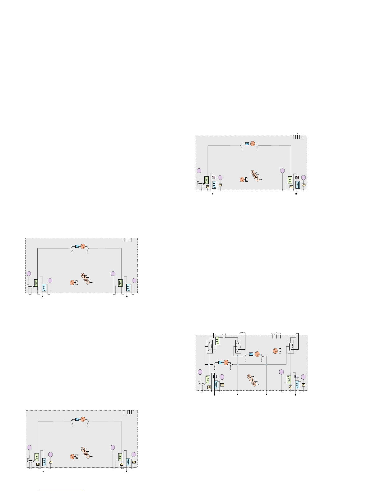
PNA-X Series test set and power conguration options
The PNA-X is an integrated vector network analyzer featuring
a built-in S-parameter test set, one or two synthesized sources
used for device stimulus, a solid-state drive, USB interfaces,
and a 10.4” LCD touch screen display. The N5241A, N5242A, and
N5249A have 50 ohm, ruggedized 3.5 mm (m) test ports. The
N5244A and the N5245A have 50 ohm, ruggedized 2.4 mm (m)
test ports. The N5247A has 50 ohm, ruggedized 1.85 mm (m)
test ports. Included with each instrument is a mouse, keyboard
(U.S. style), and one day of on-site productivity assistance
(PS-S20-PNA).
A test set and power conguration option is mandatory, choose
one of the following:
2-port standard test set and power range
(Option 200)
The standard 2-port test set comes with six front-panel access
loops. The loops provide access to the signal path between (a)
the source output and the reference receiver, (b) the source
output and directional coupler thru arm and (c) the coupled arm
of the directional coupler and the port receiver. The standard
test set also includes a solid-state internal RF transfer switch in
the R1 reference-receiver path.
High-power congurable and extended power
range (N524xAS Option H85/285)
With extended power range and bias-tees (Option 219), the
internal bias-tees limit the maximum test por t input power to
+30 dBm. The N524xAS Option H85/285 removes the bias-tees
between the source attenuators and the test port couplers. This
extends the maximum port power that the analyzer can safely
handle to +43 dBm. Selecting OptionH85/285 adds internal
attenuators and cables. The N524xAS Option H85/285 and
Option 219 can not be ordered together. Option H85/285 is not
available for the N5247A. When ordering, select N524xAS then
add items N524xAS-H85, N524xAS-285 and N524xA-200.
1
Extended power range and bias-tees (Option 219)
Adds to the standard test set one 65 dB for N5241/42/49A,
60 dB for N5244/45A, and 50 dB for N5247A source attenuator
(set table in 5 dB increments for N5241/42/49A and 10 dB increments for N5244/45/47A), one 35 dB receiver attenuator (settable
in 5 dB increments) for N5241/42/44/45/49A and 50 dB receiver
attenuator (settable in 10 dB increments) for N5247A, and one
bias-tee to each test port. Option 219 requires Option 200.
Add an internal second source, a combiner
and mechanical switches to 2-port analyzer
(Option 224)
Available with 2-port model only, this option adds an internal
second source, a combiner and mechanical switches. The internal second source provides an additional signal (xed or swept)
for two-tone third-order-intercept (TOI) and intermodulation
testing of ampliers, or it can be used as a fast swept-LO signal
for xed-IF testing of mixers and converters. The mechanical
switches provide increased exibility by having rear panel access
(front panel access for N5247A Source 1 and 2 Out 1) to signal
paths for advanced applications. Access to the second source
is available through two output connectors on the front panel.
Requires Options 200, 219 and 080.
1. The block diagrams shown above include hardware that must be ordered
as separate options, such as pulse generators (Option 025), pulse modulators (Options 021 and 022), and IF access (Option 020). In addition, the
combiner type and attenuator values vary by model number. Refer to the
product data sheet for the correct block diagram for a specic model.
9 | Keysight | PNA Family Microwave Network Analyzers - Congurations Guide
Test port 3
C
R3
Test port 1
R1
Test port 4
R4
Test port 2
R2
A
D
B
To receivers
LO
Pulse generators
rear panel
1
2
3
4
Source 1
OUT 1 OUT 2
Pulse
modulator
Source 2
(standard)
OUT 1 OUT 2
Pulse
modulator
J9J10J11 J8 J7 J2 J1J4 J3
35 dB 35 dB 35 dB
35 dB
65 dB 65 dB 65 dB 65 dB
J6 J5
RF
OUT
LO
OUT
R A B C D
IF inputs
Test port 3
C
R3
Test port 1
R1
Test port 4
R4
Test port 2
R2
A D B
Source 2
OUT 1 OUT 2
Pulse
modulator
Source 1
OUT 1 OUT 2
Pulse
modulator
Pulse generators
To receivers
LO
R A B C D
IF inputs
rear panel
Test port 3
C
R3
Test port 1
R1
Test port 4
R4
Test port 2
R2
35 dB
65 dB
35 dB
65 dB 65 d B
35 dB
65 dB
A
35 dB
D B
Source 2
OUT 1 OUT 2
Pulse
modulator
Source 1
OUT 1 OUT 2
Pulse
modulator
Pulse generators
To receivers
LO
R A B C D
IF inputs
rear panel
Test port 3
C
R3
Test port 1
R1
Test port 4
R4
Test port 2
R2
35 dB
65 dB
35 dB
65 dB 65 dB
35 dB
65 dB
A
35 dB
D B
Source 2
OUT 1 OUT 2
Pulse
modulator
Source 1
OUT 1 OUT 2
Pulse
modulator
Pulse generators
To receivers
LO
R A B C D
IF inputs
rear panel
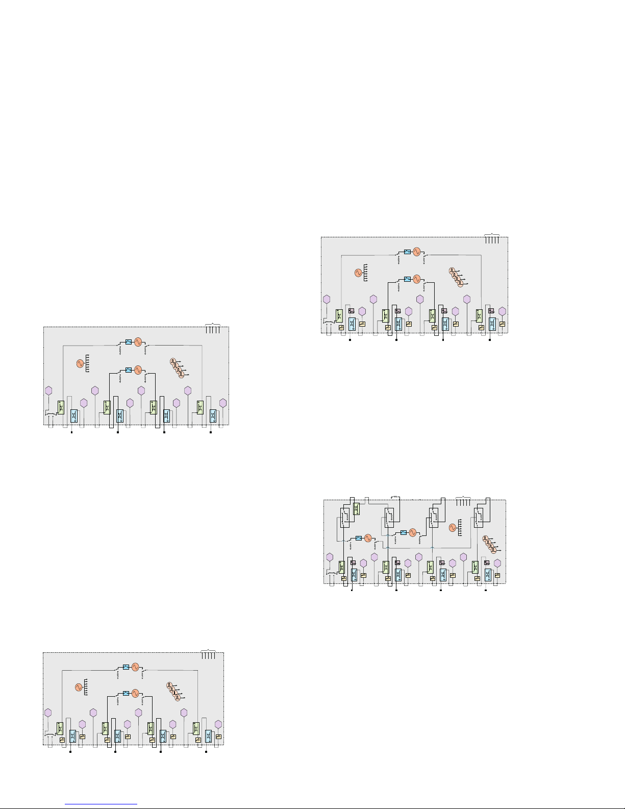
PNA-X Series test set and power conguration options
4-port standard test set, power range and an
internal second source (Option 400)
The standard 4-port test set comes with 12 front-panel access
loops and a built-in second source. The loops provide access to
the signal path between (a) the source output and the reference
receiver, (b) the source output and directional coupler thru arm
and (c) the coupled arm of the directional coupler and the port
receiver. The internal second source provides an additional signal
(xed or swept) for two-tone third-order-intercept (TOI) and
intermodulation testing of ampliers, or it can be used as a fast
swept-LO signal for xed-IF testing of mixers and converters.
With two sources, source 1 is accessible through test ports 1
and 2, and source 2 is accessible through test ports 3 and 4.
The standard test set also includes a solid-state internal RF
transfer switch in the R1 reference-receiver path. Option 080 is
recommended.
Extended power range and bias-tees
(Option 419)
Adds to the standard test set one 65 dB for N5241/42/49A, 60 dB
for N5244/45A, and 50 dB for N5247A source attenuator (settable in 5 dB increments for N5241/42/49A and 10 dB increments
for N5244/45/47A), one 35 dB receiver attenuator (settable in
5 dB increments) for N5241/42/44/45/49A and 50 dB receiver
attenuator (settable in 10 dB increments) for N5247A, and one
bias-tee to each test port. Option 419 requires Option 400.
1
(continued)
High-power congurable and extended power
range (N524xAS Option H85/485)
With extended power range and bias-tees (Option 419), the
internal bias-tees limit the maximum test por t input power to
+30 dBm. The N524xAS Option H85/485 removes the bias-tees
between the source attenuators and the test port couplers. This
extends the maximum port power that the analyzer can safely
handle to +43 dBm. Selecting Option H85/485 adds internal attenuators and cables. The N524xAS Option H85/485 and Option
419 can not be ordered together. Option H85/485 is not available
for the N5247A. When ordering, select N524xAS then add items
N524xAS-H85, N524xAS-485 and N524xA-400.
Add an internal combiner and mechanical
switches to 4-port analyzer (Option 423)
Available with 4-port model only, this option adds a combiner
and mechanical switches. The mechanical switches provide
increased exibility by having rear panel access (front panel
access for the N5247A Source 1 and 2 Out 1) to signal paths for
advanced applications. Requires Options 400, 419 and 080.
1. The block diagrams shown above include hardware that must be ordered
as separate options, such as pulse generators (Option 025), pulse modulators (Options 021 and 022), and IF access (Option 020). In addition, the
combiner type and attenuator values vary by model number. Refer to the
product data sheet for the correct block diagram for a specic model.

10 | Keysight | PNA Family Microwave Network Analyzers - Congurations Guide
Test port 1 Test port 2
A B
R1
R2
Source
OUT 1OUT 2
Pulse
modulator
To receivers
LO
Pulse generators
RABCD
IF inputs
rear panel
R1
R2
35 dB
65 dB 65 dB
A
35 dB
B
Source
OUT 1OUT 2
Pulse
modulator
To receivers
LO
Pulse generators
RABCD
IF inputs
rear panel
Test port 1
R1
Test port 2
R2
A B
Source
OUT 1OUT 2
Pulse
modulator
To receivers
LO
Pulse generators
RABCD
IF inputs
rear panel
Test port 1
R1
Test port 2
R2
35 dB
65 dB 65 dB
A
35 dB
B
Source
OUT 1OUT 2
Pulse
modulator
To receivers
LO
Pulse generators
RABCD
IF inputs
rear panel
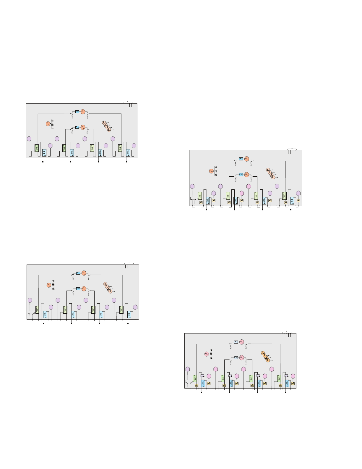
PNA Series test set and power conguration options
The PNA is an integrated vector network analyzer featuring a
built-in S-parameter test set, one or two synthesized sources
used for device stimulus, a solid-state drive, USB interfaces, and
a 10.4” LCD touch screen display. The N5221A and the N5222A
have 50 ohm, ruggedized 3.5 mm (m) test ports. The N5224A
and the N5225A have 50 ohm, ruggedized 2.4 mm (m) test ports.
The N5227A has a 50 ohm, ruggedized 1.85 mm (m) test ports.
Included with each instrument is a mouse, keyboard (U.S. style),
and one day of on-site productivity assistance (PS-S20-PNA).
A test set and power conguration option is mandatory, choose
one of the following:
2-ports, single source, base conguration (Option
200/210)
The 2-port with base conguration has no front-panel access
loops.
1
2-ports, single source, with extended power range
(Option 217)
The 2-port test set with extended power range comes with a
congurable test set, source and receiver attenuators at each
port. For N5221/22A, the source attenuators are 65 dB in 5 dB
steps and the receiver attenuators are 35 dB in 5 dB steps. For
N5224/25A, the source attenuators are 60 dB in 10 dB steps and
the receiver attenuators are 35 dB in 5 dB steps. Also included
is a solid-state internal RF transfer switch in the R1 referencereceiver path. This conguration is not available on N5227A.
2-ports, single source, with congurable test set
(Option 201)
The 2-port congurable test set comes with six front-panel access loops. The loops provide access to the signal path between
(a) the source output and the reference receiver, (b) the source
output and directional coupler thru arm and (c) the coupled arm
of the directional coupler and the port receiver at all por ts. Also
included is a solid-state internal RF transfer switch in the R1
reference-receiver path.
2-ports, single source, with extended power range
and bias-tee (Option 219)
The 2-port test set with extended power range and bias-tee
comes with a congurable test set, source and receiver attenuators, and bias-tee at each port. For N5221/22A, the source
attenuators are 65 dB in 5 dB steps and the receiver attenuators
are 35 dB in 5 dB steps. For N5224/25A, the source attenuators
are 60 dB in 10 dB steps and the receiver attenuators are 35 dB
in 5 dB steps. For N5227A, both source and receiver attenuators
are 50 dB in 10 dB steps. Also included is a solid-state internal
RF transfer switch in the R1 reference-receiver path.
1. The block diagrams shown above include hardware that must be ordered
as separate options, such as pulse generators (Option 025), pulse modulators (Options 021 and 022), and IF access (Option 020). In addition, the
attenuator values var y by model number. Refer to the product data sheet
for the correct block diagram for a specic model.
11 | Keysight | PNA Family Microwave Network Analyzers - Congurations Guide
Test port 3
R3
Test port 1 Test port 4
R4
Test port 2
R2
R1
A C D B
Source 2
OUT 1OUT 2
Pulse
modulator
Source 1
OUT 1OUT 2
Pulse
modulator
Pulse generators
To receivers
LO
RABCD
IF inputs
rear panel
Test port 3
C
R3
Test port 1
R1
Test port 4
R4
Test port 2
R2
35 dB
65 dB
35 dB
65 dB 65 dB
35
dB
65 dB
A
35 dB
D B
Source 2
OUT 1OUT 2
Pulse
modulator
Source 1
OUT 1OUT 2
Pulse
modulator
Pulse generators
To receivers
LO
RABCD
IF inputs
rear panel
Test port 3
C
R3
Test port 1
R1
Test port 4
R4
Test port 2
R2
A D B
Source 2
OUT 1OUT 2
Pulse
modulator
Source 1
OUT 1OUT 2
Pulse
modulator
Pulse generators
To receivers
LO
RABCD
IF inputs
rear panel
Test port 3
C
R3
Test port 1
R1
Test port 4
R4
Test port 2
R2
35 dB
65 dB
35 dB
65 dB 65 dB
35
dB
65 dB
A
35 dB
D B
Source 2
OUT 1OUT 2
Pulse
modulator
Source 1
OUT 1OUT 2
Pulse
modulator
Pulse generators
To receivers
LO
RABCD
IF inputs
rear panel
PNA Series test set and power conguration options
4-ports, dual source, base conguration
(Option 400/410)
The 4-port with base conguration has no front-panel access
loops.
4-ports, dual source, with congurable test set
(Option 401)
The 4-port congurable test set comes with two internal sources,
twelve front-panel access loops. The loops provide access to
the signal path between (a) the source output and the reference
receiver, (b) the source output and directional coupler thru arm
and (c) the coupled arm of the directional coupler and the port
receiver at all ports. Also included is a solid-state internal RF
transfer switch in the R1 reference-receiver path.
4-ports, dual source, with extended power range
(Option 417)
The 4-port test set with extended power range comes with
two internal sources, congurable test set, source and receiver
attenuators at each port. For N5221/22A, the source attenuators
are 65 dB in 5 dB steps and the receiver attenuators are 35 dB in
5 dB steps. For N5224/25A, the source attenuators are 60 dB in
10 dB steps and the receiver attenuators are 35 dB in 5 dB steps.
Also included is a solid-state internal RF transfer switch in the
R1 reference-receiver path. This conguration is not available on
N5 2 27A .
4-ports dual source, with extended power range
and bias-tee (Option 419)
The 4-port test set with extended power range and bias-tee
comes with two internal sources, congurable test set, source
and receiver attenuators, and bias-tee at each port. For
N5221/22A, the source attenuators are 65 dB in 5 dB steps and
the receiver attenuators are 35 dB in 5 dB steps. For N5224/25A,
the source attenuators are 60 dB in 10 dB steps and the receiver
attenuators are 35 dB in 5 dB steps. For N5227A, both source
and receiver attenuators are 50 dB in 10 dB steps. Also included
is a solid-state internal RF transfer switch in the R1 referencereceiver path.
1
(continued)
1. The block diagrams shown above include hardware that must be ordered
as separate options, such as pulse generators (Option 025), pulse modulators (Options 021 and 022), and IF access (Option 020). In addition, the
attenuator values var y by model number. Refer to the product data sheet
for the correct block diagram for a specic model.
12 | Keysight | PNA Family Microwave Network Analyzers - Congurations Guide
Test port 1
Source
Test port 2
To receivers
LO
A
R1
B
R2
Source
Test port 1
A
Test port 4
Test port 2
B
Test port 3
R
To receivers
LO
C
D
Test port 1 Test port 2
A B
R2R1
60 dB 60 dB
Source
To receivers
LO
Source
Test port 1
A
Test port 4
D
60 dB
Test port 2
B
Test port 3
C
R
To receivers
LO
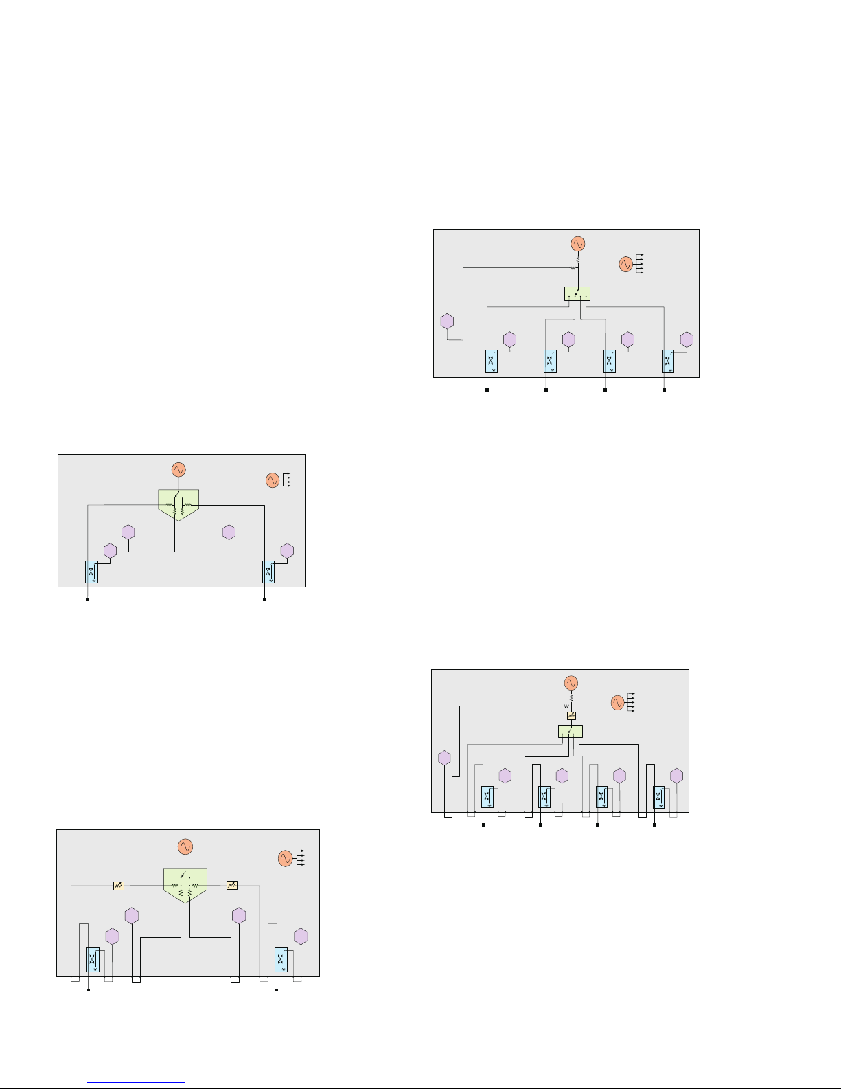
PNA-L Series test set and power conguration options
The PNA-L is an integrated vector network analyzer featuring a
built-in S-parameter test set, one synthesized source used for
device stimulus, a solid state drive, USB interfaces, and a 10.4”
LCD touch screen display. The N5239A, N5231A and the N5232A
have 50 ohm, ruggedized 3.5 mm (m) test ports. The N5234A
and N5235A have 50 ohm, ruggedized 2.4 mm (m) test ports.
Included with each instrument is a mouse, keyboard (U.S. style).
For one day of on-site productivity assistance (not included with
instrument purchase), request quantity 1 each PS-S20-PNA.
A test set and power conguration option is mandatory, choose
one of the following:
2 ports, single source, base conguration (Option
200)
The 2-port with base conguration has no front-panel access
loops.
2 ports, single source, with congurable test set
and source attenuators (Option 216)
The 2-port test set comes with a congurable test set and
source attenuator at each port. The congurable test set adds six
front-panel access loops. The loops provide access to the signal
path between (a) the source output and the reference receiver,
(b) the source output and directional coupler thru arm, and (c) the
coupled arm of the directional coupler and the port receiver at all
ports. The source attenuators are 60 dB in 10 dB steps.
4 ports, single source, base conguration (Option
400)
The 4-port base conguration has no front-panel loops, and is
available only on the N5231A and N5232A.
4 ports, single source, with congurable test set
and source attenuator (Option 416)
The 4-port test set comes with a congurable test set and one
source attenuator to be shared with all ports. The congurable
test set adds nine front-panel access loops. The loops provide
access to the signal path between (a) the source output and the
reference receiver, (b) the source output and directional coupler
thru arm at all ports, and (c) the coupled arm of the directional
coupler and the port receiver at all ports. The source attenuator
is 60 dB in 10 dB steps. This conguration is available on only
N5231A and N5232A.
 Loading...