

Page 1

FieldFox Handheld Analyzer Software
Page 2

An All-In-One Analyzer for Field System
Page 2
Find us at www.keysight.com
Installation, Verification, and Maintenance
As high-frequency technologies develop and extend beyond the lab,
the need for portable, high-performance test gear increases. FieldFox
handheld analyzers are able to withstand the toughest RF and microwave
measurement environments regardless of test site location. Install, verify,
and maintain systems in the field using one unit that supports over 25
measurement capabilities.
FieldFox’s software options provide the same precision and accuracy
as the Keysight equipment on your lab bench. You can customize your
configuration at initial purchase or upgrade later with license keys that you
can quickly and easily install in the field. There is no need to send the unit
back to upgrade it.
Page 3

FieldFox Family Overview
Page 3
Find us at www.keysight.com
FieldFox offers two series in the product family that differ in frequency
range and bandwidth. The A-Series models have frequency coverage
from 100 kHz to 50 GHz with 10 MHz of bandwidth, while the B-Series
models have frequency coverage from 9 kHz to 54 GHz and up to 120 MHz
of bandwidth. To see a side-by-side comparison of the A-Series versus
B-Series specifications, please see the flyer FieldFox Microwave Analyzers:
B-Series vs. A-Series Specifications.
FieldFox has three base configurations to choose from — vector network
analyzer (VNA), cable and antenna tester (CAT), and signal analyzer (SA).
You can also configure your unit as a combination analyzer that supports all
of the base functions and more. Figure 1 shows a visual representation of
the FieldFox family of instruments.
Frequency
Combination Analyzer
CAT + VNA + SA
VNA
Signal Analyzer
4 GHz 6.5 GHz 9 GHz 14 GHz 18 GHz 26.5 GHz 32 GHz 44 GHz 50 GHz 54 GHz
N9952A / B
N9951A / B
N9950A / B
N9918A / B
N9917A / B
N9916A / B
N9915A / B
N9914A / B
N9913A / B
N9912A-106
N9912A-104
N9923A-106
N9923A-104
N9934B
N9933B
No RTSA
N9982A
N9927A
N9926A
N9925A
N9962A / B
N9961A / B
N9960A / B
N9938A / B
N9937A / B
N9936A / B
N9935A / B
N9953B
N9963B
Figure 1. A visual representation of the FieldFox family, base configurations, and frequency coverage
Page 4

FieldFox Measurement Options and
Page 4
Find us at www.keysight.com
Compatible Instruments
Once you choose your base model, customize FieldFox with the
measurement options that meet your needs. The tables below list several
FieldFox software option bundles that appear by application. The tables
also indicate the instruments that support each option.
Cellular communications
Option
number
233 Spectrum analyzer
235 Pre-amplifier
236
307 GPS receiver External
312 Channel scanner
350
352
358
370 Over-the-air (OTA) LTE FDD —
371 Over-the-air (OTA) LTE TDD —
377 Over-the-air (OTA) 5G TF —
378 Over-the-air (OTA) 5G NR — —
B04
B10
Interference analyzer and
spectrogram
Real-time spectrum
analyzer (RTSA)
Indoor and outdoor
mapping
Electromagnetic field (EMF)
measurements
Analysis bandwidth,
40 MHz
Analysis bandwidth,
120 MHz
Description Combination analyzers
N9912A
N9913/4/5/6/7/8A
N9950/51/52A
ü ü ü
ü ü ü
ü ü ü
ü ü ü
—
—
—
— —
— —
N9913/14/15/16/
17/18B
N9950/51/52/53B
ü ü
ü ü
ü ü
ü ü
ü ü
ü ü
ü ü
ü
ü
ü
Vector nerwork
analyzers (VNA)
N9923A N9925/26/27/28A
— — Base model Base model
— —
— —
External
— —
— —
— —
— —
— —
— —
— —
— — —
— — —
— — —
Spectrum analyzers
N9935/36/37/38A
N9960/61/62A
ü ü
ü ü
ü ü ü
ü ü
ü ü
ü ü
ü ü
ü ü
ü ü
ü ü
N9933/34/35/36/
37/38B
N9960/61/62/63B
ü
ü
ü
Option
number
010 VNA time domain
112 QuickCal
Extended range
209
210 VNA transmission/reflection
211
transmission analysis
(ERTA)
VNA full 2-port
S-parameters
Satellite and radar communications
Description Combination analyzers
N9912A
N9913/4/5/6/7/8A
N9950/51/52A
ü ü ü ü ü
ü
—
ü ü ü
—
ü
(N991xA only)
ü ü
ü ü ü ü
N9913/14/15/16/
N9950/51/52/53B
Vector nerwork
analyzers (VNA)
17/18B
ü ü ü
N9923A N9925/26/27/28A
— —
Base
model
Base model — —
Spectrum analyzers
N9935/36/37/38A
N9960/61/62A
— —
— —
ü ü
— —
N9933/34/35/36/
37/38B
N9960/61/62/63B
Page 5

Satellite and radar communications (continued)
Page 5
Find us at www.keysight.com
Option
number
215 TDR cable measurements —
233 Spectrum analyzer
235 Pre-amplifier
302 USB power sensor support
305 Cable and antenna analyzer
307 GPS receiver External
310 Built-in power meter
320
350
351 I/Q analyzer (IQA) —
352 Indoor and outdoor mapping —
356 Noise figure (NF) —
B10
Reflection meas. (RL,
VSWR and scalar meas.)
Real-time spectrum
analyzer (RTSA)
Analysis bandwidth,
120 MHz
Description Combination analyzers
N9912A
ü ü ü
ü ü ü
ü ü ü ü ü ü ü
Base
model
ü ü ü
—2 —2 —2 —2 —2
—
— —
N9913/4/5/6/7/8A
N9950/51/52A
ü ü
Base model Base model
ü ü
ü ü
ü ü
ü ü
ü ü
N9913/14/15/16/
17/18B
N9950/51/52/53B
ü
Vector nerwork
analyzers (VNA)
N9923A N9925/26/27/28A
—
— — Base model Base model
— —
ü ü
External
—
— —
— —
— —
— —
— — —
ü
ü ü ü
ü ü ü
Spectrum analyzers
N9935/36/37/38A
N9960/61/62A
— —
ü ü
— —1
ü ü
ü ü
ü ü
ü ü
ü ü
N9933/34/35/36/
37/38B
N9960/61/62/63B
ü
Automotive (RF/MW) testing
Option
number
210 VNA transmission/reflection
211 VNA full 2-port S-parameters —
233 Spectrum analyzer
235 Pre-amplifier
236
302 USB power sensor support
307 GPS receiver External
312 Channel scanner
330
350
352 Indoor and outdoor mapping —
355 Analog demodulation —
361
370 Over-the-air (OTA) LTE FDD —
371 Over-the-air (OTA) LTE TDD —
378 Over-the-air (OTA) 5G NR — —
B10
Interference analyzer and
spectrogram
Pulse measurement with
USB peak power sensor
Real-time spectrum
analyzer (RTSA)
Electromagnetic interference
(EMI) measurements
Analysis bandwidth,
120 MHz
Description Combination analyzers
N9912A
N9913/4/5/6/7/8A
N9950/51/52A
ü ü ü
ü ü ü
ü ü ü
ü ü ü
ü ü ü ü ü ü ü
ü ü ü
ü ü ü ü ü ü ü
—
— —
— —
Vector nerwork
analyzers (VNA)
N9913/14/15/16/
17/18B
N9950/51/52/53B
ü ü ü ü
ü ü
ü ü
ü ü
ü ü
ü
ü ü
ü ü
ü
ü
N9923A N9925/26/27/28A
Base
model
External
Base model — —
— — Base model Base model
— —
— —
— —
— —
— —
— —
— — —
— —
— —
— — —
— — —
Spectrum analyzers
N9935/36/37/38A
N9960/61/62A
— —
ü ü
ü ü
ü ü ü
ü ü
ü ü
ü ü
ü ü
ü ü
ü ü
N9933/34/35/36/
37/38B
N9960/61/62/63B
ü
ü
ü
Page 6
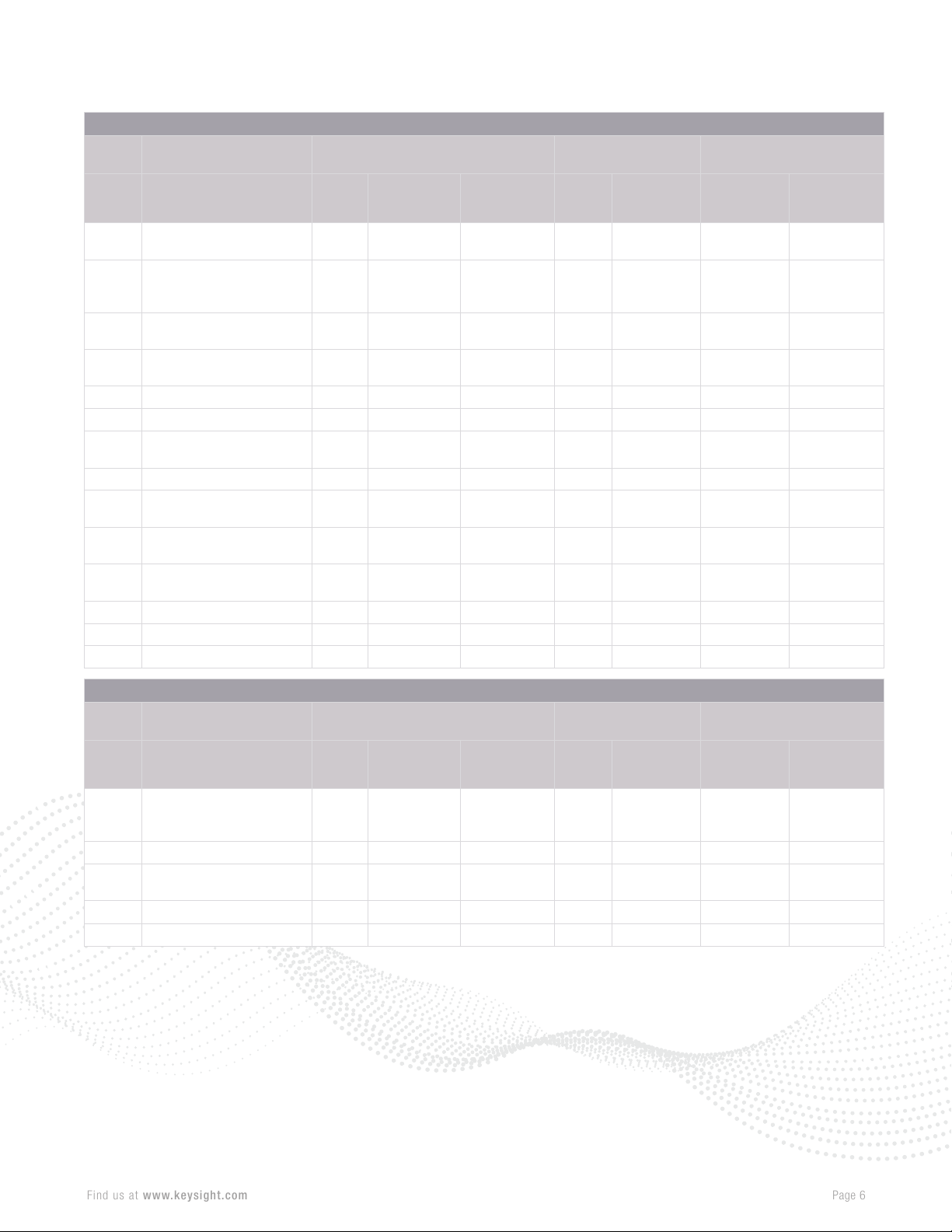
Option
Page 6
Find us at www.keysight.com
number
112 QuickCal
USB power sensor
208
210 VNA transmission/reflection
211
215 TDR cable measurements —
233 Spectrum analyzer
236
302 USB power sensor support
305 Cable and antenna analyzer
330
350
351 I/Q analyzer (IQA) —
355 Analog demodulation —
356 Noise figure (NF) —
measurement versus
frequency
VNA full 2-port
S-parameters
Interference analyzer and
spectrogram
Pulse measurement with
USB peak power sensor
Real-time spectrum
analyzer (RTSA)
Description Combination analyzers
N9912A
Base
model
General purpose / education
Vector nerwork
analyzers (VNA)
N9913/4/5/6/7/8A
N9950/51/52A
ü
ü ü ü ü ü ü ü
ü ü ü
—
ü ü ü
ü ü ü
ü ü ü ü ü ü ü
ü ü ü ü ü ü ü
—
ü
(N991xA only)
ü ü ü ü
ü ü
Base model Base model
ü ü
ü ü
ü ü
ü ü
N9913/14/15/16/
17/18B
N9950/51/52/53B
ü ü ü
N9923A N9925/26/27/28A
Base
model
—
— — Base model Base model
— —
ü ü
— —
— —
— —
— —
Base model — —
ü
Spectrum analyzers
N9935/36/37/38A
N9960/61/62A
— —
— —
— —
ü ü
— —1
ü ü
ü ü
ü ü
ü ü
N9933/34/35/36/
37/38B
N9960/61/62/63B
Additional options
Option
number
USB power sensor
208
220 Tracking generator —3 —3
238
310 Built-in power meter
353 IQ streaming —
measurement versus
frequency
Spectrum analyzer time
gating
Description Combination analyzers
N9912A
N9913/4/5/6/7/8A
N9950/51/52A
ü ü ü
—
ü ü ü
ü ü
ü ü
N9913/14/15/16/
N9950/51/52/53B
17/18B
Vector nerwork
analyzers (VNA)
N9923A N9925/26/27/28A
ü ü
— —
— —
—
ü
— —
Spectrum analyzers
N9935/36/37/38A
N9960/61/62A
ü ü
ü ü
ü ü
ü ü
ü ü
N9933/34/35/36/
37/38B
N9960/61/62/63B
Page 7
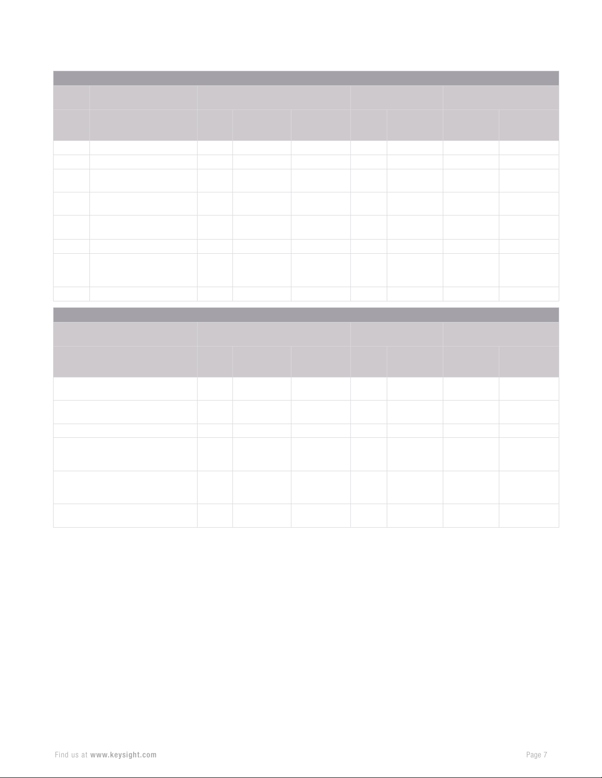
Option
Page 7
Find us at www.keysight.com
number
030 Remote control capability
307 GPSreceiver External
309
352
360
— SCPI support
— OML mixer support —
— Datalink
DC bias variable-voltage
source
Indoor and outdoor
mapping
Phased array antenna
support
Description Combination analyzers
N9912A
ü ü ü ü ü ü ü
—
—
—
ü ü ü ü ü ü ü
ü ü ü ü ü ü ü
Utilities
Vector nerwork
analyzers (VNA)
N9913/4/5/6/7/8A
N9950/51/52A
ü ü
ü ü ü ü ü ü
ü ü
ü
(N995xA only)
ü
(N9916 to
52A only)
N9913/14/15/16/
17/18B
N9950/51/52/53B
ü
ü
(N9916 to
53B only)
N9923A N9925/26/27/28A
External
— —
— —
— —
ü ü ü
Spectrum analyzers
N9935/36/37/38A
N9960/61/62A
ü ü
ü
(N996xA only)
ü
(N9936 to
62A only)
N9933/34/35/36/
37/38B
N9960/61/62/63B
ü
ü
(N9936 to
63B only)
Description Combination analyzers
N9912A
Materials Measurement Suite
(N1500A)
PathWave Vector Signal Analysis
(VSA 89600)
Signal Surveyor (N6820ES) —
PathWave BenchVue FieldFox
Handheld Analyzer Control &
Automation App (BV0010B)
PathWave BenchVue Network
and Spectrum Analyzer Control &
Automation App (BV9001B)
WaveJudge Wireless Analyzer Toolset
(SJ001A)
1. Option 305 is not available on the N993x/6xB. A subset of CAT measurements, return loss, and VSWR, is available as Option
320.
2. Option 320 is not applicable to models N991xA/B,N995xA/B, or N992xA. These models include reflection measurements of
return loss and VSWR. There is no need for an Option 320 on these analyzers.
3. On the N991xA/B or N995xA/B model analyzers, order Options 233 and 210 to obtain a tracking generator with the
spectrum analyzer. There is no Option 220 on these analyzers. Option 233 provides the spectrum analyzer capability and
Option 210 offers the “tracking” capability.
N9913/4/5/6/7/8A
N9950/51/52A
ü ü ü ü ü
—
ü ü
— —
— —
ü ü
ü ü
N9913/14/15/16/
17/18B
N9950/51/52/53B
ü
(N9917B only)
ü
(N9917B only)
ü
Vector nerwork
analyzers (VNA)
N9923A N9925/26/27/28A
— —
— —
ü ü ü
— — — —
— — —
Spectrum analyzers
N9935/36/37/38A
N9960/61/62A
— —
ü ü
ü ü
N9933/34/35/36/
N9960/61/62/63B
37/38B
—
ü
Page 8
FieldFox Measurement Options Overview
Page 8
Find us at www.keysight.com
You need to perform routine maintenance, occasional troubleshooting,
and repair of your networks in the toughest working environments.
FieldFox software options enable you to keep mission-critical systems
operating smoothly. Several options and utilities are described below.
030 – Remote control capability with iOS or
Android devices
• Monitor and control FieldFox remotely using your
iOS or Android device.
• Press any key and turn the knob of the unit from
your iOS/Android device using an emulated
FieldFox front panel.
• Access technical documents such as data sheets
instantly.
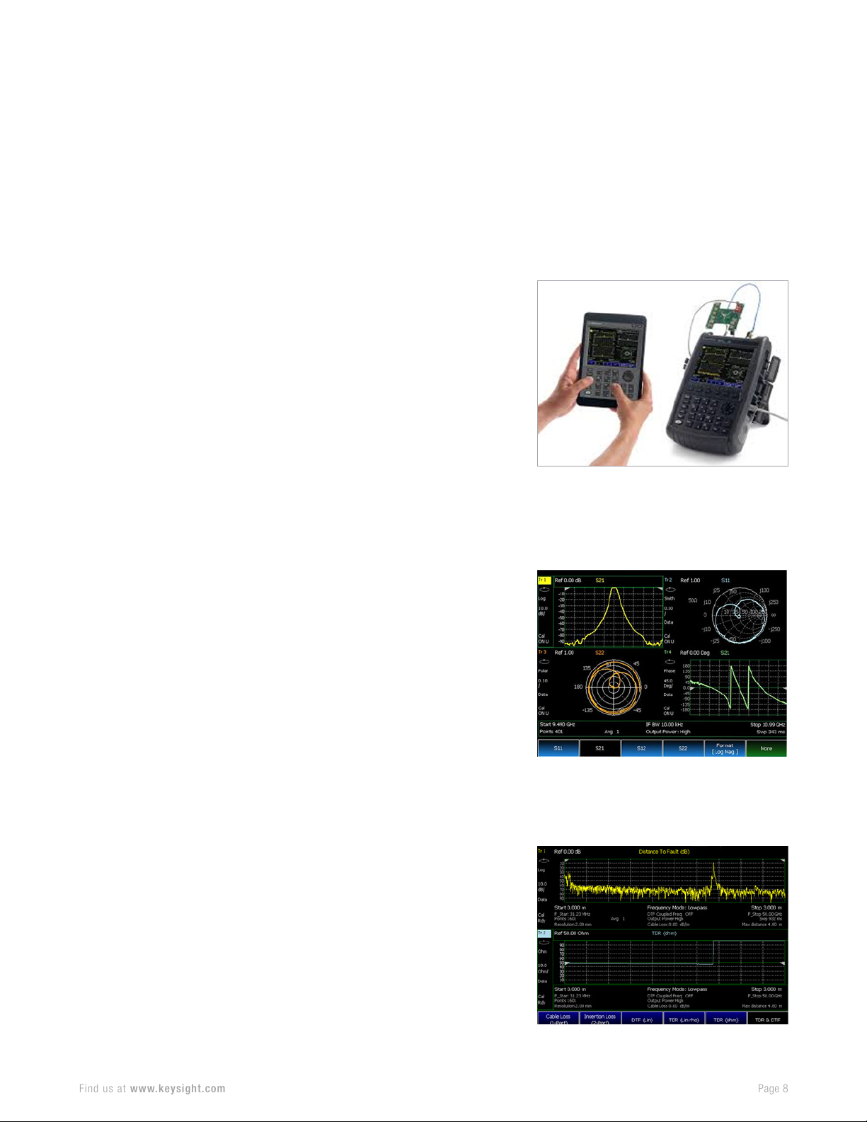
211 – Vector network analyzer (VNA) two-port
S-parameters
• Measure all four S-parameters, magnitude, and
phase characteristics of your component without
having to disconnect the DUT, turn it around, and
reconnect it to the analyzer.
• Get the best measurement accuracy possible
with full, two-port calibration.
• Measure high rejection, narrowband devices such
as cavity filters with 117 dB of dynamic range.
• Measure non-insertable devices accurately and
easily with two-port error correction.
• Use Keysight’s microwave expertise to deliver field
measurements consistent with benchtop VNAs.
215 – Time-domain reflectometry (TDR) cable
measurements
• Measure impedance changes along the cable and
identify specific faults.
• Characterize the type of fault, including inductive
or capacitive discontinuities.
• Measure distance-to-fault (DTF) and TDR in a
single sweep.
Page 9
233 – Spectrum analyzer
Page 9
Find us at www.keysight.com
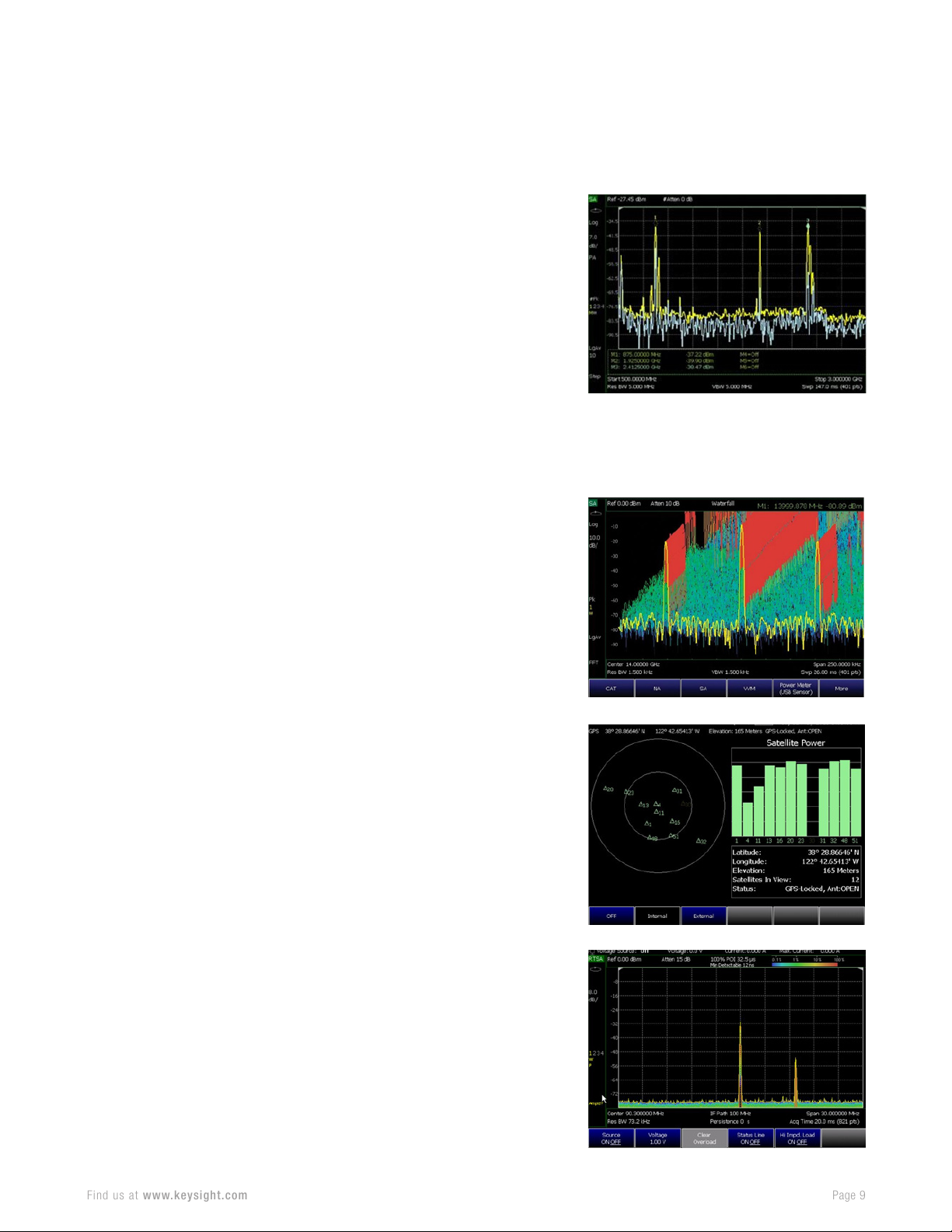
• Monitor for unexpected signals and perform
signal surveillance of dynamic spectral
environments.
• Detect a low-level signal under strong signal
conditions or close-in small interference signals
with superior dynamic range (TOI +15 dBm,
DANL -148 dBM/Hz with preamp off), close-in
phase noise (-117 dBc/Hz at 10 kHz offset for a 1
GHz carrier), and fast sweep time.
• Simplify power measurements for a variety of
radio standards with full power suites.
• Enable lab-grade measurement accuracy with no
warm-up time.
236 – Interference analyzer
• Identify interfering signals quickly and maintain
quality of service (QoS) of your network.
• Detect intermittent signals or monitor signals over
a period of time with spectrogram and waterfall
displays.
• Record signal traces into internal memory or
external flash memory devices for offline processing.
307 – Global navigation satellite system (GNSS) /
global positioning system (GPS) receiver
• Collect geo-location tags and match them to
measurements.
• Display and save the geodata — time, latitude,
longitude, and elevation — in data files.
309 – DC bias variable voltage source
• Provide DC power to amplifiers under test and
bias tower mounted amplifiers (TMA) when you
need to sweep through the TMA to reach the
antenna. Bias tees are available separately.
Page 10
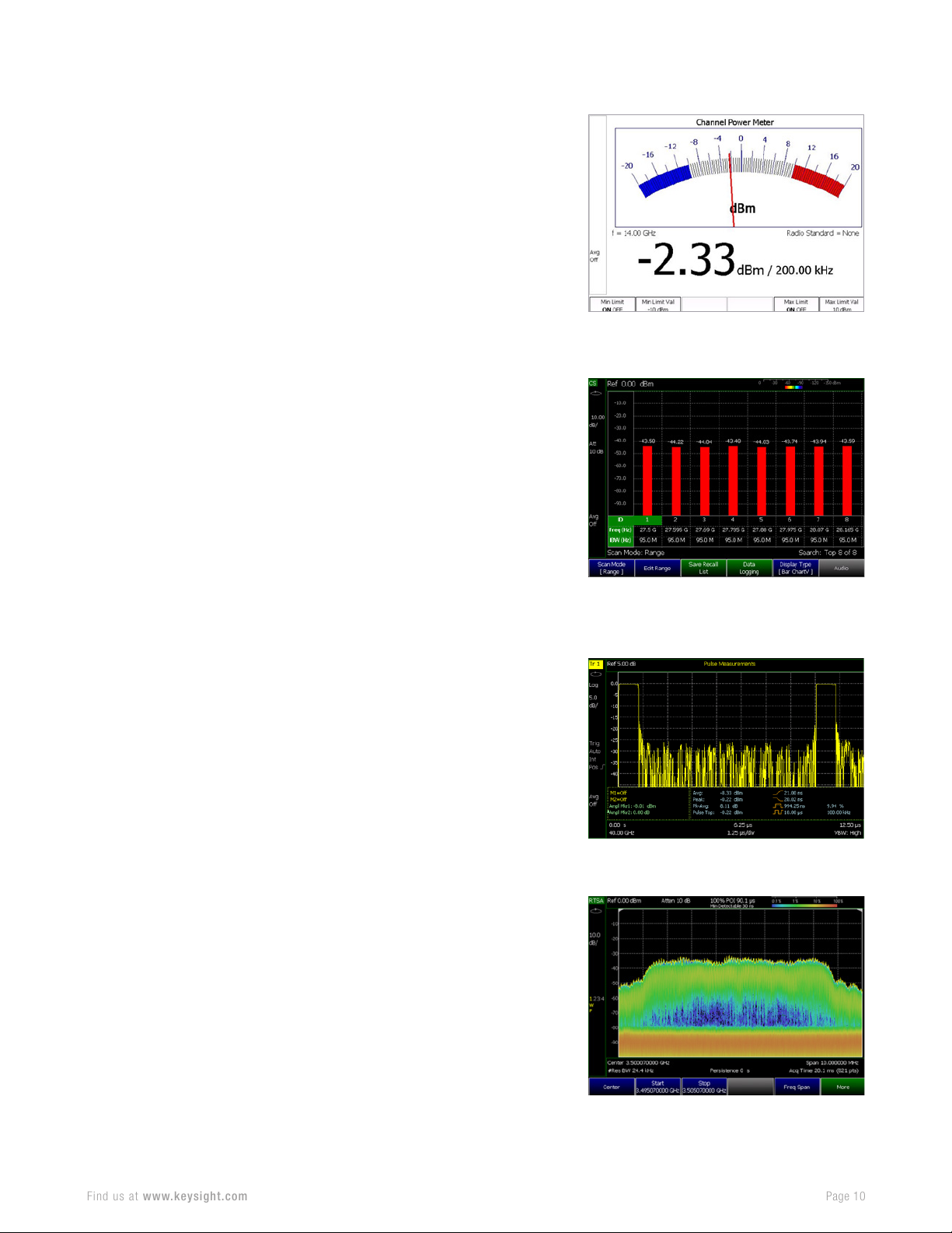
310 – Built-in power meter
Page 10
Find us at www.keysight.com
• Make accurate, user-definable channel power
measurements such as transmitter output power
with no additional external hardware.
• View measurements easily by emulating the
power meter user interface with analog and digital
displays.
312 – Channel scanner
• Make up to 20 channel power measurements
simultaneously and verify wireless network coverage,
path loss, and potential interference issues.
• Measure primary carriers and their intermodulated
products.
• Customize frequency and bandwidth settings for
each channel.
• Use time interval logging and geotagging to export
files to Google Earth for network coverage analysis.
• Record and play back the data with datalogging.
330 – Pulse measurements
• Characterize pulsed RF signals efficiently and
obtain important key performance indicators (KPIs)
by using Keysight’s USB peak power sensors.
• Measure peak power, average power, and peakto-average ratio.
• Check radar signal quality in the field with a
lightweight, portable unit.
350 – Real-time spectrum analyzer (RTSA)
• Acquire gap-free signal data with real-time
bandwidth up to 120 MHz.
• Detect signals as short as 5.52 µs with 100%
probability of intercept (POI) and full amplitude
accuracy.
• Visualize a low-level signal in the presence of a highpower transmitter using the spectrum density view.
• Find an elusive signal quickly using FieldFox’s
recording and playback to analyze saved data offline.
Page 11
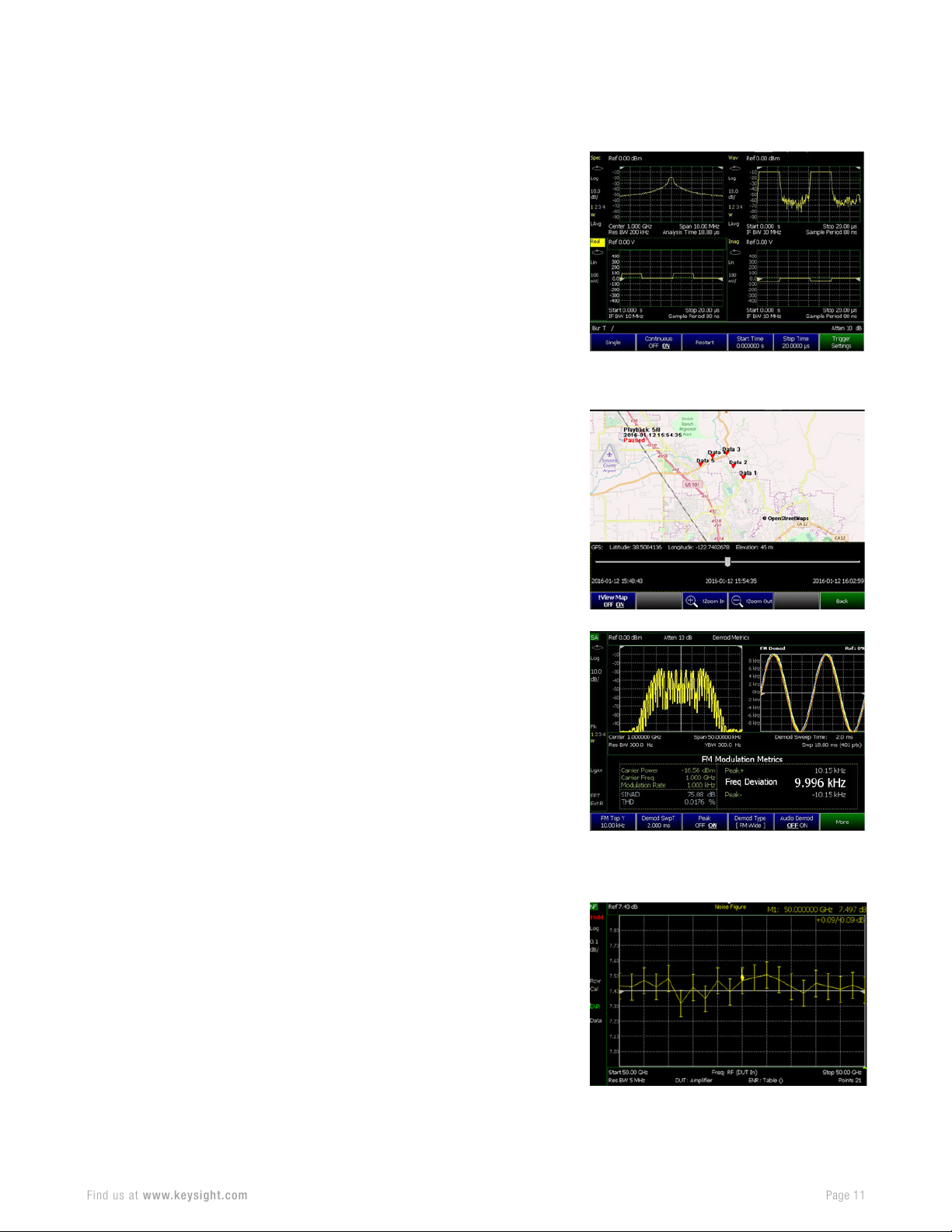
351 – I/Q analyzer
Page 11
Find us at www.keysight.com
• Verify final signal chain integration.
• Troubleshoot signal quality degradation.
• Customize the display with up to four simultaneous
and multi-domain measurement views.
• Enhance performance with features such as
amplitude and intermediate frequency (IF)
alignment before capture.
• Provide gapless in-phase and quadrature (IQ)
data to external application software to perform
spectrum monitoring, demodulation, and decoding.
352 – Indoor and outdoor mapping
• Import and display maps from OpenStreetMap
(OSM) for data collection and mapping.
• Save maps to internal memory, SD card, or
USB port.
• Use the FieldFox Map Support Tool to download
OSM maps or use a direct wired local area
network (LAN) connection.
355 – AM/FM analog demodulation
• Characterize AM/FM radio transmitters.
• Tune to a signal and listen to the audio tones with
the built-in speakers or a headphone.
• Measure AM/FM metrics such as carrier power,
modulation rate, signal-to-noise and distortion (SINAD)
with a full selection of post-demodulation filters.
356 – Noise figure (NF)
• Quantify the signal-to-noise ratio (SNR)
degradation caused by components in the link.
• Use the industry-proven Y-factor technique to
accurately verify and characterize device noise figures.
• Receive real-time measurement integrity feedback
on measurement data that includes built-in
uncertainty calculator error bars.
• Optimize gain to avoid compression and
measurement time to achieve jitter goal.
• Define loss compensation for dB lost before and
after device under test (DUT).
Page 12
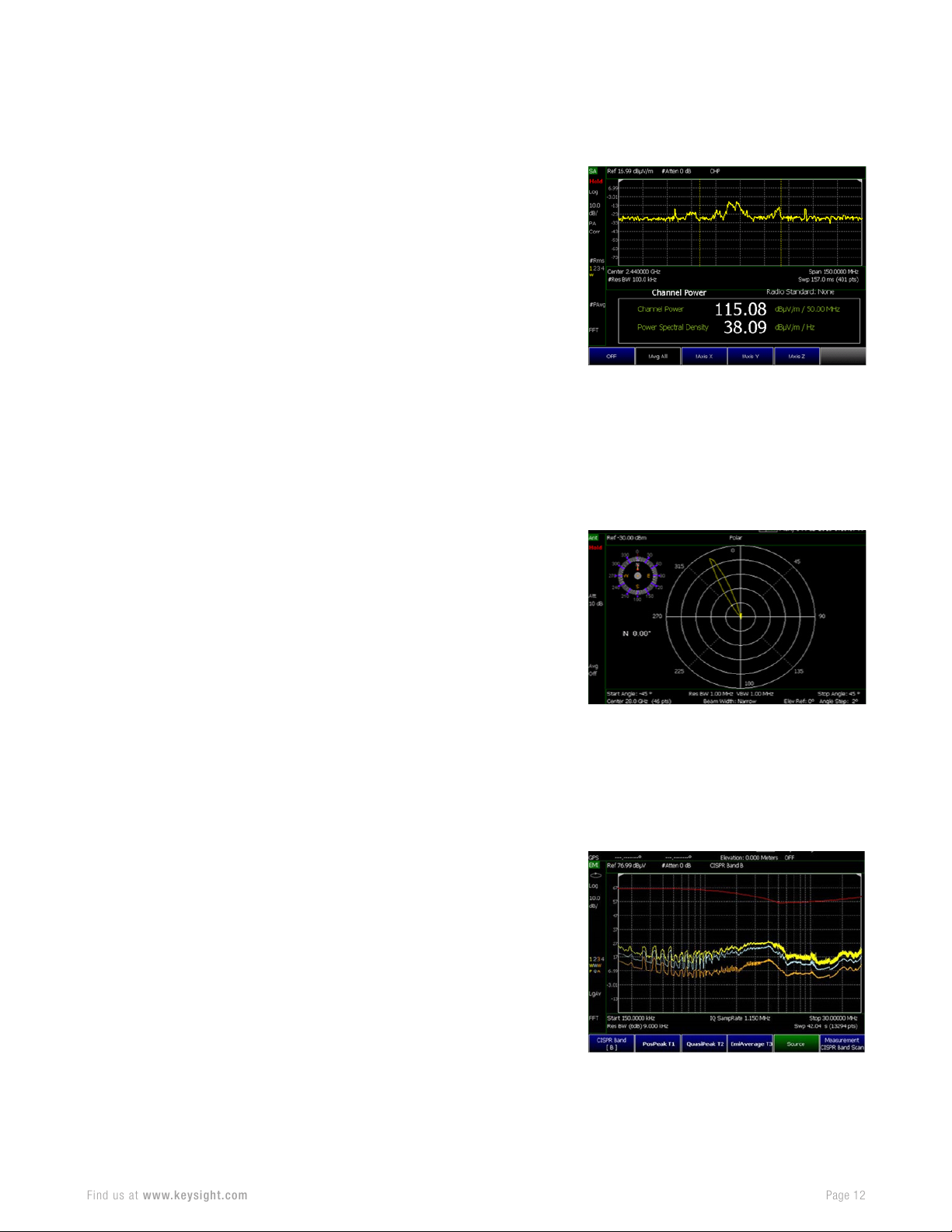
358 – Electromagnetic field measurements (EMF)
Page 12
Find us at www.keysight.com
• Evaluate total (RF) exposure in any given RF and
microwave environment.
• Verify compliance to exposure levels set by
government and regulatory agencies.
• Measure the total field strength across the
frequency band of interest.
• Connect to AGOS Advanced Technologies’
Triaxial Isotropic Antenna, model SDIA-6000, for
measurements.
• Record, recall, and playback data with geolocation information for post-processing analysis.
360 – Phased array antenna support
1
• Support a 64-element, single polarization phased
array antenna with coverage from 27.5 to 30 GHz.
• Understand g-Node-B (gNB) beam characteristics
by measuring signal power level across azimuth
and elevation from base stations.
• Reduce measurement complexity with an
integrated RF probe and phased array solution to
capture energy radiated from the gNB.
• Simulate 5G user equipment (UE) and antenna
performance.
• Verify phased array performance with boresight,
polar antenna pattern with compass, and heat
map (azimuth versus elevation) displays.
361 – Electromagnetic interference (EMI)
measurements
• Evaluate pre-compliance limits prior to formal
compliance tests.
• Identify issues such as noise floor rise and
interference that other equipment generates.
• Perform equipment or network regulatory audits
against various limits, such as CISPR 16-1-1.
• Troubleshoot circuit boards.
• Test potential system level performance impact
due to EMI degradation.
1. Purchase a supported phased array antenna directly from Anokiwave, or from Keysight as product number 85571A-028.
Please contact us to understand delivery lead time.
Page 13
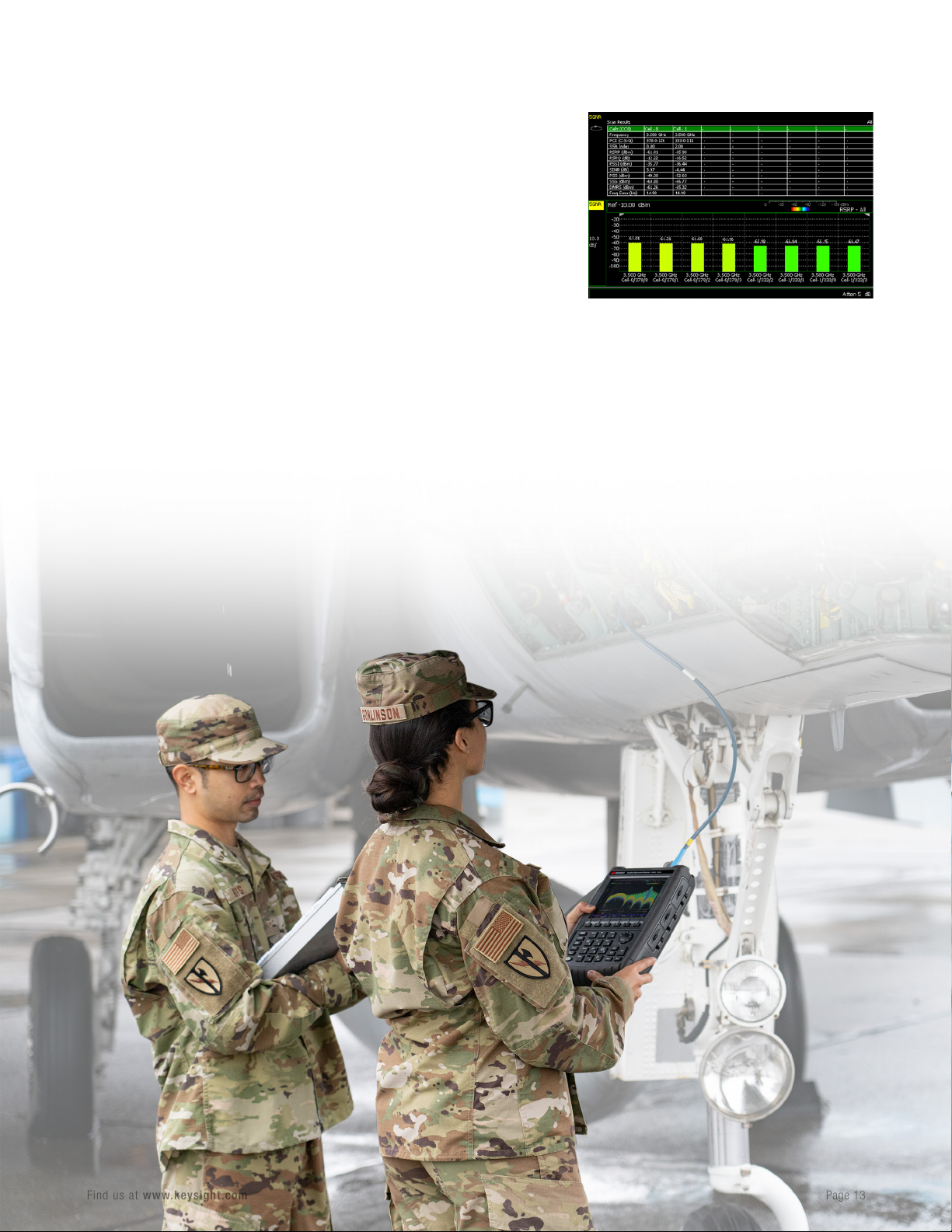
378 – 5G NR over-the-air (OTA) measurements
Page 13
Find us at www.keysight.com
• Characterize air interface path loss and beam
coverage.
• Verify the quality of the network and beam
performance.
• Measure and decode primary synchronization
signal (PSS), secondary synchronization signal
(SSS), beam indexes, cell ID, and various signal
quality metrics.
• Identify frequency drifting, isolate power issues,
investigate performance problems, and verify
Inter-RAT handovers.
• Analyze 5G NR frequency range 1 (FR1) and
frequency range 2 (FR2) up to millimeter-wave
(mmWave) without requiring an external mixer.
Page 14

Conclusion
Page 14
Find us at www.keysight.com
FieldFox’s software options enable a customized solution to meet your
measurement needs wherever you go. Configure your unit at purchase or
upgrade later as your needs change. With over 25 different measurement
options and frequency coverage up to 54 GHz, FieldFox is the most wellequipped tool to keep your network up and running in the field.
Learn More
To learn more about the various options you see in this brochure,
download our Technical Overviews.
• A-Series Technical Overview
• B-Series Technical Overview
• FieldFox 5G gNB Field Test Solution Technical Overview
• 5G mmWave Air Interface Characterization with Phased
Array Antenna Technical Overview
To understand the different ways that you can customize
FieldFox to meet your needs, download our Configuration Guides.
• A-Series Configuration Guide
• B-Series Configuration Guide
Page 15

This information is subject to change without notice. © Keysight Technologies, 2021 - 2022, Published in USA, February 17, 2022, 7121-1262.EN
 Loading...