

Page 1

F ind us at www.keys ight.com Pa ge 1
FieldFox Handheld Analyzers
4/6.5/9/14/18/26.5/32/44/50/54 GHz
This configuration guide describes configurations, options, and accessories for
the FieldFox B-Series family of portable analyzers. Use this guide, along with
the technical overview and data sheet, for a complete description of the
analyzers. The table on page 3 titled “FieldFox B-Series Family and Options”
shows a comparison of the functions available in the FieldFox B-Series family
of analyzers.
Note: Combination analyzer (combo) = Cable and antenna tester (CAT) +
Vector network analyzer (VNA) + Signal analyzer (SA).
Included Accessories
The following accessories
are included with every
FieldFox:
•
AC/DC adapter
•
Battery
•
Soft carrying case
•
LAN cable
Page 2

Fi nd us at www.keysight.com Pa ge 2
Table of Contents
FieldFox B-Series Family and Options
...................................................................................................... 3
FieldFox RF and Microwave (Combination) Analyzers
.............................................................................. 4
Analyzer options
.......................................................................................................................................... 5
FieldFox RF and Microwave (Combination) Analyzer FAQs
..................................................................... 6
ERTA System Typical Configuration ........................................................................................................... 10
FAQs – Applicable to all FieldFox RF and Microwave Analyzers
.......................................................... 11
FieldFox Signal Analyzers ........................................................................................................................... 13
Analyzer options .......................................................................................................................................... 13
FieldFox Signal Analyzer FAQs .................................................................................................................. 14
Upgrades ..................................................................................................................................................... 15
FieldFox Signal Analyzer Upgrades ............................................................................................................ 16
Documentation ............................................................................................................................................ 18
Calibration Kits ............................................................................................................................................ 18
Accessories ................................................................................................................................................. 19
Page 3

Fi nd us at www.keysight.com Pa ge 3
FieldFox B-Series Family and Options
Option
Description
Combination Analyzers
N9913/4/5/6/7/8B
N9950/1/2/3B
Signal Analyzers
N9933/4/5/6/7/8B
N9960/1/2/3B
CAT / vector network analysis
010
VNA time domain ✓ —
210
VNA transmission/reflection
✓
—
211
VNA full 2-port S-parameters
✓
—
212
1-port mixed-mode S-parameters
✓
—
215
TDR cable measurements
✓
—
305
Cable and antenna analyzer
Base model 1
— 2
308
Vector voltmeter ✓ —
320
Reflection meas. (RL, VSWR and scalar meas.)
— 3
✓
Spectrum analysis
209
Extended range transmission analysis (ERTA)
✓
✓
220
Tracking generator
— 4
✓
233
Spectrum analyzer
✓
Base model 1
235
Pre-amplifier
✓
✓
236
Interference analyzer and spectrogram
✓
✓
238
Spectrum analyzer time gating
✓
✓
312
Channel scanner
✓
✓
350
Real-time spectrum analyzer (RTSA)
✓
✓
351
I/Q analyzer (IQA)
✓
✓
352
Indoor and outdoor mapping
✓
✓
353
IQ streaming
✓
✓
355
Analog demodulation
✓
✓
356
Noise figure (NF)
✓
✓
358
EMF measurements
✓
✓
360
Phased array antenna support
✓
✓
361
EMI measurements
✓
✓
370
Over-the-air (OTA) LTE FDD
✓
✓
371
Over-the-air (OTA) LTE TDD
✓
✓
377
Over-the-air (OTA) 5G TF
✓
✓
378
Over-the-air (OTA) 5G NR
✓
✓
B04
Analysis bandwidth, 40 MHz 5
✓
✓
B10
Analysis bandwidth, 120 MHz 5
✓
✓
Power measurements
208
USB power sensor meas. versus frequency
✓
✓
302
USB power sensor support
✓
✓
310
Built-in power meter
✓
✓
330
Pulse meas. with USB peak power sensor
✓
✓
1. Ba se mo de l f un ction ality list ed is t he pr imary func ti on of th at i ns tru me nt. F or ex am ple , on th e N99 1x /5x B com bo anal yz ers , cable
an d ant en na an alyze r is the s ta ndard func tion inclu de d wit h eve ry N9 91 x/5 xB .
2. Op tio n 305 i s not avai la ble o n t he N993x/ 6xB . A sub set o f measu remen ts, r et urn l oss a nd VS WR , i s avail abl e as O pti on 32 0.
3. Op tio n 320 i s not a ppl ic abl e to N9 91x/5 xB. T he N991 x/ 5xB i ncl ud es re flect io n m ea surem en ts of re tu rn lo ss an d VSW R as st andar d
fu nctio ns.
4. On the N991x /5xB an aly ze rs, o rder Optio ns 23 3 and 2 10 to obta in a tr ack in g gen er ator wit h the s pectr um an al yzer. Ther e is no
Op tion 22 0 o n the N 991x/ 5xB a na lyz er s. Op tion 23 3 p ro vid es the sp ect ru m ana lyzer capabi lit y and O ption 2 10 th e “tr ac kin g”
ca pabil ity.
5. 10 MH z stand ar d.
Page 4

Fi nd us at www.keysight.com Pa ge 4
FieldFox RF and Microwave (Combination) Analyzers
Analyzer models
Step 1. Select the model that provides the desired frequency range.
Model
Description
CAT and VNA frequency
SA frequency 2
Test port connectors
N9913B
4 GHz FieldFox RF analyzer
30 kHz to 4 GHz
9 kHz to 4 GHz
Type-N (f)
N9914B
6.5 GHz FieldFox RF analyzer
30 kHz to 6.5 GHz
9 kHz to 6.5 GHz
Type-N (f)
N9915B
9 GHz FieldFox microwave analyzer
30 kHz to 9 GHz
9 kHz to 9 GHz
Type-N (f)
N9916B
14 GHz FieldFox microwave analyzer
30 kHz to 14 GHz
9 kHz to 14 GHz
Type-N (f)
N9917B
18 GHz FieldFox microwave analyzer
30 kHz to 18 GHz
9 kHz to 18 GHz
Type-N (f)
N9918B
26.5 GHz FieldFox microwave analyzer
30 kHz to 26.5 GHz
9 kHz to 26.5 GHz
3.5 mm (m)
N9950B
32 GHz FieldFox microwave analyzer
300 kHz to 32 GHz
9 kHz to 32 GHz
2.4 mm (m)
N9951B
44 GHz FieldFox microwave analyzer
300 kHz to 44 GHz
9 kHz to 44 GHz
2.4 mm (m)
N9952B
50 GHz FieldFox microwave analyzer
300 kHz to 50 GHz
9 kHz to 50 GHz
2.4 mm (m)
N9953B
54 GHz FieldFox microwave analyzer
300 kHz to 54 GHz
9 kHz to 54 GHz
1.8 mm (m)
1. Mo de ls N9 91 3/33B , N9914 /3 4B an d N9915 /3 5B do n ot su pport f reque nc y ext en ders. T his i s bec au se the mixer s’ star ting LO
fr eq uen cy is h ig her t ha n 9 G Hz an d the F ieldFox P ort 1 prov id es th e LO to the mi xer. For a list o f sup po rt ed OM L fre qu ency
ex te nde rs , see A cc ess ories p ag e 22.
2. Us eab le to 5 k Hz.
Option
Description
Combination Analyzers
N9913/4/5/6/7/8B
N9950/1/2/3B
Signal Analyzers
N9933/4/5/6/7/8B
N9960/1/2/3B
System features
030
Remote control capability
✓
✓
307
GPS receiver
✓
✓
309
DC bias variable-voltage source
✓
✓
—
Frequency extender support 1
✓
✓
Windows based software
89601B
PathWave VSA (89600 VSA) software
✓
✓
N6820ES
Surveyor 4D software
✓
✓
Page 5

Fi nd us at www.keysight.com Pa ge 5
Analyzer options
Step 2. Select optional measurement capabilities.
Any of these options can easily be added as a software upgrade in the future.
Option
Description
Prerequisite options/notes
CAT / vector network analysis
010
VNA time domain
Requires 210, recommend 211. See FAQ #7
210
VNA transmission/reflection
Recommend ordering a calibration kit. See FAQ #4 and FAQ #6
211
VNA full 2-port S-parameters
Requires 210, recommend ordering a calibration kit. See FAQ #5
212
1-port mixed-mode S-parameters
Requires 210 and 211
215
TDR cable measurements
—
308
Vector voltmeter
210 and 211 required for full VVM functionality. See FAQ #8
Spectrum analysis
209
Extended range transmission analysis
(ERTA)
Requires 233 and 210. Recommend 307. Requires two FieldFox units. See FAQ # 9.
See page 10 for typical configuration.
233
Spectrum analyzer
—
235
Pre-amplifier
Requires 233
236
Interference analyzer and spectrogram
Requires 233
238
Spectrum analyzer time gating
Requires 233
312
Channel scanner
Requires 233. Require the corresponding option to support a specific app. For example,
to support EMF in channel scanner requires 358.
350
Real-time spectrum analyzer (RTSA)
Requires 233, Recommend 235. See FAQ # 11
351
I/Q Analyzer (IQA)
Requires 233
352
Indoor and outdoor mapping
Requires 233, 307, and at least one of 312, 360, 370, 371, 377 or 378. See FAQ #15
353
IQ streaming
Requires 233 and 351
355
Analog demodulation
Requires 233
356
Noise Figure (NF)
Requires 233, 235, 309 and accessory item N9910X-713 BNC to SMB cable. See FAQ
#13 for external preamplifier and noise source requirements.
358
EMF measurements
Requires 233. Also requires triaxial antenna. See FAQ #16
360
Phased array antenna support
Requires 233. Also requires phased array antenna. N991x/3xB (x > 5) models require
external mixer. No external mixer required for N995x/6xB models. See FAQ #14
361
EMI measurements
Requires 233
370
Over-the-air (OTA) LTE FDD
Requires 233 and 307. Recommend 235.
371
Over-the-air (OTA) LTE TDD
Requires 233 and 307. Recommend 235.
377
Over-the-air (OTA) 5G TF
Requires 233 and 307. Recommend 235. N991x/3xB (x > 5) models require external
mixer. See FAQ #14 No external mixer required for N995x/6xB models. 5G TF is pre-5G
standard
378
Over-the-air (OTA) 5G NR
Requires 233, B10, and 307. Recommend 235. N991x/3xB (x > 5) models require
external mixer for FR2 frequencies above 26.5 GHz. See FAQ #18. No external mixer
required for N995x/6xB models.
B04
Analysis bandwidth, 40 MHz 1
Requires 233. Recommend 350, 351 or PathWave VSA (formerly 89600 VSA) software
B10
Analysis bandwidth, 120 MHz 1
Requires 233. Recommend 350, 351, 378 or PathWave VSA (formerly 89600 VSA)
software.
Power measurements
208
USB power sensor meas. versus frequency
Requires 302. See FAQ I
302
USB power sensor support
Need to order USB power sensor 2. See FAQ A
310
Built-in power meter
No power sensor required. See FAQ B
330
Pulse meas. with USB peak power sensor
Requires 302 and USB peak power sensor. See FAQ G and FAQ H
1
. 10 MHz st and ar d.
2. L ist o f com patib le se ns ors a vaila ble f rom www.k eysig ht .co m/ find/ field foxsu pp ort .
Page 6

Fi nd us at www.keysight.com Pa ge 6
Option
Description
Prerequisite options/notes
System features
030
Remote control capability
Requires an iOS device or an Android device
307
GPS receiver
Need to order GPS antenna, N9910X-825. See FAQ C
309
DC bias variable-voltage source
Recommend N9910X-713 cable. See FAQ D
—
Frequency extender support
Requires 233. Optional 350, 351, 360, 370, 371, 377, 378, PathWave VSA (formerly
89600 VSA) software. See Accessories, page 22
Windows based software
89601B
PathWave VSA (89600 VSA) software
Requires 233
N6820ES
Surveyor 4D software
Requires 233, 235 and 307. See FAQ #17
FieldFox RF and Microwave (Combination) Analyzer FAQs
Question
Answer
1. What is included with a base
N991x/5xB analyzer?
The base model includes the cable and antenna analyzer
Measurements: DTF (dB, linear, VSWR), return loss and DTF, return loss (dB), and 1-port cable loss
Calibrations: CalReady, OSL, and response calibration
Note: 2-port insertion loss is NOT included with the base model, if 2-port insertion loss is needed, order
Option 210
Note: Base analyzer does not have phase information, for S11 or S21 phase, order Option 210
2. What is included with N991x/5xB
Option 233?
Basic spectrum analysis, four traces, different detector types, radio standard selection, limit lines
Channel power, occupied bandwidth, adjacent channel power, spectrum emission mask
AM/FM tune and listen, field strength measurements, antenna factors, frequency counter marker
Tracking generator (TG)/Independent source:
• TG CW mode (source CW frequency can be set independent of SA frequency) - included
• TG CW coupled mode (source CW frequency auto coupled to SA’s center frequency) - included
• TG tracking mode (traditional TG operation, swept SA coupled to swept source) - (requires Option 210)
3. What is included with N991x/5xB
Option 236?
Interference analyzer and spectrogram, trace playback and recording
4. What is included with N991x/5xB
Option 210?
Option 210 adds a VNA with transmission/reflection (T/R) capability
Measurements: S21, S11, magnitude and phase
Additionally, in the CAT mode, you can measure 2-port insertion loss
Calibrations: CalReady, OSL, response, and enhanced response calibration
If you need all four S-parameters, order Options 210 and 211
If you need 2-port calibration, order Options 210 and 211
Adds tracking mode to the tracking generator/independent source included with Option 233, spectrum
analyzer
5. What is included with N991x/5xB
Option 211?
Option 211 adds full 2-port S-parameter capability to the VNA mode
Measurements: All four S-parameters (S11, S21, S22, S12), magnitude and phase
Calibrations: CalReady, OSL, response, enhanced response, and full 2-port calibration
Page 7

Fi nd us at www.keysight.com Pa ge 7
Question
Answer
6. Can I measure group delay on
N991x/5xB analyzers?
If you have phase measurement capability, then you can measure group delay. Option 210 is required for
any phase measurement capability. So, if you do not have Option 210, you cannot measure group delay.
7. What is included with N991x/5xB
Option 010?
S11/S21 in time domain if Option 210 is ordered. To get time domain data for all four S-parameters and full
2-port calibration, order Option 211.
View both time and frequency domain data at the same time
Low-pass, impulse, and band-pass modes
Minimum, medium, and maximum window
Gating
8. What is included with N991x/5xB
Option 308?
With Option 308: 1-port cable trimming
With Options 308 and 210: 1-port cable trimming, 2-port transmission
With Options 308, 210, and 211: 1-port cable trimming, 2-port transmission, A/B and B/A
Note: A/B and B/A measurements require an external source
9. What are the requirements for
Option 209?
Extended Range Transmission Analysis (ERTA) or Option 209 is a scalar measurement system based on
the use of two (2) FieldFox units. One FieldFox acts as the source and reference receiver, while the
second FieldFox acts as the measurement receiver. When different frequency models are used in an
ERTA pair, the system frequency range is limited to the lowest of the pair.
Required hardware
A. Two (2) FieldFox units. FieldFox units can be any of these models:
• FieldFox combination analyzers: N9913/14/15/16/17/18/50/51/52/53B
• FieldFox signal analyzers: N9933/34/35/36/37/38/60/61/62/63B
The two FieldFox units used in ERTA do not have to be the same model.
ERTA requires the following options on Combo FieldFox models (N9913/14/15/16/17/18/50/51/52/53B):
• Option 210, VNA transmission/reflection
• Option 233, spectrum analyzer
ERTA requires the following options on SA FieldFox models (N9933/34/35/36/37/38/60/61/62/63B)
• Option 220, tracking generator
Both FieldFox units (the one used as the source, and the other used as the receiver) must have the
options listed above. The ERTA option (209) cannot be installed unless 210 and 233 are present on a
combo analyzer; or 220 is present on a SA analyzer.
With either the Combo or SA FieldFox units, the following options are highly recommended:
• Option 235, preamplifier – this option increases the measurement dynamic range by increasing the
received signal power
• Option 307, GPS receiver – this option increases the dynamic range by increasing the frequency
accuracy and permitting the use of a narrower RBW
B. Power splitter, two-resistor model, Keysight 11667A, 11667B, or 11667C. Other power splitters can be
used but the specifications listed are based on the match and tracking performance of 11667A, 11667B, or
11667C. Three-resistor power splitters are not recommended.
C. N9910X-712, Trigger/Reference-in cable, SMA (m) to BNC(f), 1 m, quantity two
D. N9910X-713, Trigger/Reference-out cable, SMB (m) to BNC (m), 1 m, quantity two
E. LAN connection – For ERTA, the two FieldFox units communicate via a LAN connection. For a direct
connection, a LAN cable is required. Or, both analyzers can be on a local area network.
Recommended accessory
F. N9910X-825, GPS Antenna. Necessary if Option 307 is ordered.
10. What is included with Option 355?
FieldFox analog demodulation has two parts: (1) Tune and listen, and (2) AM/FM metrics. Tune and listen
is available with the purchase of the spectrum analyzer option 233. AM/FM metrics becomes available
when Option 355 is purchased. AM/FM metrics provides the user with RF spectrum view, demodulated
baseband signal waveform, carrier power, frequency deviation, SINAD and more.
Page 8

Fi nd us at www.keysight.com Pa ge 8
Question
Answer
11. What is included with Option 350?
Real-time spectrum analyzer (RTSA) or Option 350 provides real-time measurements. The FieldFox must
be equipped with spectrum analysis capability. The preamplifier option is recommended, as elusive signals
often have low power levels. The real-time bandwidth options include 10 MHz (standard), 40 MHz (Option
B04), or 120 MHz (Option B10). RTSA includes trace recording and playback capabilities. It does not
include a frequency-mask trigger (FMT).
12. Is Spectrum Analyzer Trace
Recording and Playback standard
or an option?
Spectrum Analyzer mode (Option 233) does not include Trace Recording and Playback by default. To
obtain this capability in SA mode, Option 236 Interference Analyzer and Spectrogram needs to be
purchased.
RTSA mode (Option 350) does include Trace Recording and Playback by default in RTSA mode.
Purchasing RTSA mode (Option 350) does not enable Trace Recording and Playback in SA mode (Option
233).
Trace record/playback features
SA mode
SA & Interference Analyzer
Options 233 and 236
RTSA mode
RTSA
Option 350
Record and playback spectrum traces
Yes
Yes
Save trace data with GPS time stamp over time
Yes
Yes
Record and playback spectrogram data
Yes
No 1
13. What are the requirements for
Noise figure (NF) Option 356?
Requires spectrum analyzer mode (Option 233 on combination models), internal preamplifier (Option 235)
and DC bias variable voltage source (Option 309). An external noise source is also required and FieldFox
supports Keysight noise source models 346A/B/C/K40/K01. Also recommended to improve accuracy is an
external preamplifier Keysight models U7227A/C/F or U7228A/C/F. Requires accessory item N9910X-713
BNC to SMB cable for DC bias variable voltage source to noise source connection.
14. What is required for phased array
antenna support (Option 360) and
5G NR over-the-air (OTA)
measurements (Option 378)?
Requires spectrum analyzer mode (Option 233 on combination models) and GPS receiver (Option 307).
Highly recommend internal preamplifier (Option 235). N991x/3xB (x>5) models require external mixer
since phased array antenna, which can be ordered as Keysight 85571A-028 or directly from Anokiwave as
AWMF-0129, operates at 28 GHz. See FAQ #18 for more OML mixer information. No external mixer
required for N995x/6xB models.
15. What is included with indoor and
outdoor mapping (Option 352)?
The FieldFox mapping function is available in the following modes: Channel Scanner (312), Phased-Array
Antenna (360), and OTA LTE FDD/TDD (370/371), OTA 5G TF (377), OTA 5G NR (378). Mapping is
currently not available in SA or RTSA modes. Outdoor mapping requires the availability of GPS (Option
307). Maps can be saved to the FieldFox internal memory, SD card or USB drive. Using a direct wired LAN
connection, FieldFox will automatically access OpenStreetMap (OSM) once location coordinates (latitude
and longitude) and zoom levels have been entered the Map Explorer menu. If using the l FieldFox Map
Support Tool, OSM map files can be downloaded to a .zip file and imported to FieldFox internal memory. If
the FieldFox GPS receiver is enabled and OSM maps have been previously saved to FieldFox with those
GPS coordinates, FieldFox can automatically load the corresponding map to match the current GPS
coordinates.
16. What is required for EMF
measurements (Option 358)?
Requires triaxial antenna. Supported antenna is AGOS advanced technologies Triaxial Isotropic Antenna
model SDIA-6000 30 MHz to 6 GHz. It can also be ordered as Keysight 85572A-006. EMF measurements
are supported with spectrum analyzer mode (Option 233 on combination models) and OTA 5G NR (Option
378).
1
. RT SA tr ac e r ec ordin gs ca n be re cal le d and play ed ba ck in S A mod e Spe ct rog ra m. Th is ha s the a dded benef it th at
th e mea su rem en ts ar e sho wn ‘s lo wer’, maki ng it e asi er f or th e hum an eye to de ci phe r the s ignal c ont en t.
Page 9

Fi nd us at www.keysight.com Pa ge 9
Question
Answer
17. What is required for N6820ES
Surveyor 4D Software?
Surveyor 4D software connected to FieldFox spectrum analyzer mode offers a versatile, truly portable
spectrum monitoring system that covers VLF to 50 GHz, including 5G millimeter wave bands. The software
runs on an external PC or tablet. FieldFox required options include spectrum analyzer mode (Option 233
on combination models), preamplifier (Option 235) and built-in GPS receiver (Option 307). Core Surveyor
4D software for Windows (Option N6820ES-114) is required to run the Surveyor 4D software. Other
Surveyor 4D software optional licenses that are supported include basic modulation recognition application
(N6820ES-MR1) and universal signal detection (N6820ES-USD). Requires Surveyor 4D software version
4.3 or later (May 2019). Frequencies above 26.5 GHz will require external mixer for N991x/3xB (x>5)
models. For external mixer information, FAQ #18. N995x/6xB models eliminate the external mixer
requirement.
18. What is required for 5G NR overthe-air (OTA) measurements (Option
378)?
Requires spectrum analyzer mode (Option 233 on combination models), 120 MHz analysis bandwidth
(Option B10) and GPS receiver (Option 307). Highly recommend internal preamplifier (Option 235). FR2
frequencies above 26.5 GHz will require external mixer for N991x/3xB (x>5) models. N995x/6xB models
eliminate the external mixer requirements. For Keysight direct sales, mixer is orderable as Keysight model
N9910XM28-H2A for 3.5 mm test ports or N99010xM28-H2N for type N test ports. For indirect sales, the
mixer is orderable as OML Inc. model M28H2ADC-K, please see website www.omlinc.com for more
information or contact a Keysight representative. OML mixer RF input interface is 2.92 mm (f). See Page
22 “Accessories” section for other supported OML mixers and OML frequency extender module adapter
kits.
Keysight model: N9910XM28-H2A/N9910XM28-H2N or OML model: M28H2ADC-K
Supported on FieldFox models
N9916B, N9917B, N9918B, N9936B, N9937B, N9938B
RF input frequency range
24 to 40 GHz
IF output frequency range
0.3 to 6.5 GHz
LO harmonic number
2 LO input frequency range
12 to 20 GHz
LO input power
-18 to -5 dBm
Conversion factor IF = 1 GHz
10 dB (typical)
Noise figure
12 dB
(Includes internal IF amplifier)
1. T his d iagra m is fo r O ML M28H 2A DC -K or Keys ight N9 910 XM 28 -H2A. In c ase o f Key si ght N 9910X M2 8- H2N , the m ix er co nnect ors
fo r LO Input a nd IF Outp ut ar e both Type -N. S ee “O ML fr equency exte nd er mo dules ” and “ OML f reque ncy e xt end er modu le
ad apter kits ” sec ti ons o n page 22 fo r fur th er de tai ls .
Figure 1. OML external mixer diagram 1
OML mixer IF Output (Port 2) SMA (f) to
FieldFox RF Input (Port 2) 3.5 mm (m)
OML mixer RF Input 24 to 40 GHz 2.92 mm (f)
OML mixer DC +5V SMB (m) to
FieldFox USB port +5V
OML mixer DC +5V SMB (m) to
FieldFox USB port +5V
Page 10
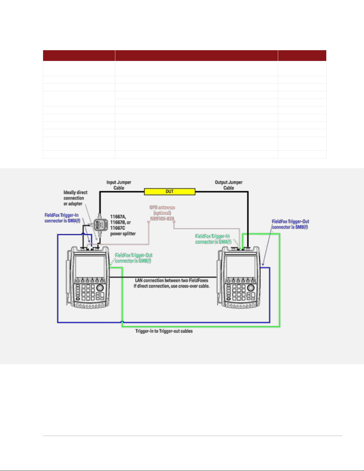
Fi nd us at www.keysight.com Pa ge 10
ERTA System Typical Configuration
Item
Description/Options
Quantity
FieldFox
Combo analyzer: Required Options 210, 233. Recommended: 235, 307
SA analyzer: Required: Option 220. Recommended: 235, 307
2
Power splitter
11667A (Type-N) or 11667B (3.5 mm)
1
Type-N(m) to Type-N(m) adapter
N9910X-850 (for use with 11667A or Type-N systems)
1
Trigger cables 1
N9910X-712, SMA(m) to BNC(f)
2 of each
N9910X-713, SMB(m) to BNC(m)
Total of 4 cables
RF test cable
Connecting FieldFox source port 1 to power splitter input
1
RF test cable or adapter
Connecting power splitter output arm to FieldFox port 2
1
RF jumper cable or adapter
Power splitter output arm to DUT input
1
RF jumper cable or adapter
DUT output to FieldFox receiver port 2
1
LAN cable
LAN cable to connect two FieldFox units directly, or the analyzers must be on
the LAN
1
N9910X-825
GPS antenna, recommended. Necessary if Option 307 is ordered.
2
1. Th e t ri gge r cable s and L AN ca bles must be at l east as lo ng as t he se pa rat io n d is tance b etw ee n t he two ends of th e DUT.
Figure 2. ERTA system diagram
Page 11
Fi nd us at www.keysight.com Pa ge 11
FAQs – Applicable to all FieldFox RF and Microwave Analyzers
Question
Answer
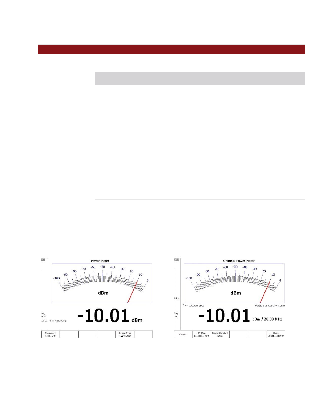
A. What USB power
sensors work with Option
302?
All Keysight U2000x Series USB power sensors are supported with FieldFox.
Visit: www.keysight.com/find/fieldfoxsupport for an up-to-date listing.
B. What is the difference
between USB power
sensor (Option 302) and
built-in power meter
(Option 310)?
Option 302
USB power sensor
Option 310
Built-in power meter (or channel power meter)
Description
Option 302 allows users to
connect a USB power
sensor to FieldFox's USB
port and make broadband
power measurements
Option 310 is a channelized power measurement
capability built into FieldFox analyzers. Maximum
bandwidth is 100 MHz.
External hardware
USB power sensor required
None. Uses internal receiver.
Power measurement
Broadband diode detector
measures all frequencies
Tuned receiver, so measures frequencies within
defined channel bandwidth
Frequency range
Depends on USB sensor
Frequency range of the analyzer
Settings
Set CW frequency
Set CW frequency, set channel width/span
Power range
Depends on USB sensor
Depends on channel width and attenuator setting
Warm-up time
30 minutes to meet accuracy
specifications
No warm-up time required
Accuracy
Depends on USB sensor
InstAlign accuracy: ± 0.5 dB typical for a CW signal.
Since the measurement is within a certain frequency
channel or bandwidth, to make an accurate
measurement, the user needs to know the exact
center frequency and the signal's bandwidth and set
those accurately.
Programmable
Yes, via SCPI
Yes, via SCPI
Physical connection
The power sensor can easily
be moved to the
measurement point, with a
USB cable connecting the
detector to FieldFox.
The measurement point needs to be connected to
FieldFox's RF input port. If an RF jumper cable is
used, the user needs to account for the loss of the
cable with an offset value (can be entered into the
analyzer).
FieldFox source control
Yes, on/off, and nominal
power level control
No access to FieldFox's source from the built-in power
meter mode
Page 12

Fi nd us at www.keysight.com Pa ge 12
Question
Answer
C. What do I need to get GPS
information?
1. The recommended GPS solution is to order:
• Option 307 - built-in GPS receiver
• A GPS antenna such as N9910X-825
• Other GPS antennas can also be used
• The connector for GPS antenna on the instrument is SMA (f)
2. Alternatively, you can purchase a USB-based GPS receiver. You do not need to purchase any FieldFox
options for the USB-based GPS to work. However, the USB-based GPS only provides time and location data,
and time synchronization capability. It cannot be used to increase the frequency accuracy of the instrument.
D. What is the connector for
Option 309, DC output?
The DC output has a SMB (m) connector. Recommend ordering N9910X Option 713 bias-tee power cable SMB
(f) to BNC (m).
E. What are the connectors for
the Reference/Trigger In and
Reference/ Trigger Out?
The connector for the Ref/Trig In is SMA (f). Recommend ordering N9910X Option 712 Trig/Ref in SMA (m) to
BNC (f) cable.
The connector for the Ref/Trig Out is SMB (m). Recommend ordering N9910X Option 713 bias-tee power cable
SMB (f) to BNC (m).
F. What is Option 030 remote
control capability?
1. Option 030 provides a license for FieldFox to allow remote control via an iOS device or an Android device.
2. Not supplied by user, but necessary for operation of Option 030 are:
• iOS device with iOS 6.1 or higher, or an Android device, with free FieldFox app
• A Wi-Fi or 3G/4G network connection between FieldFox and iOS device or an Android device
G. What USB sensor is required
for Option 330?
Option 330 or pulse measurements requires Option 302 and a Keysight USB peak power sensor. Visit
www.keysight.com/find/usbsensorsforfieldfox for a list of supported peak power sensors. Average power
sensors cannot be used with Option 330, only peak power sensors. The peak power sensor needs to be
purchased separately.
H. What measurement
capabilities are included with
Option 330?
Average power, peak power, and peak to average ratio
Analog gauge display and digital display, dBm and watts
Relative/absolute measurements, dB or %, minimum and maximum limits
Trace graph for pulse profiling with gating
Rise time, fall time, pulse width, pulse period, pulse repetition frequency
I. What is included with Option
208?
Option 302, USB power sensor measurements, includes CW power measurements (one frequency at a time).
With Option 208 added, you can make swept-frequency power measurements. You can plot source power,
gain, and receive power versus frequency. Additionally, the source frequency can be offset from the receiver
frequency. The power sensor needs to be purchased separately.
Page 13
Fi nd us at www.keysight.com Pa ge 13
FieldFox Signal Analyzers
Analyzer models
Step 1. Select the model that provides the desired frequency range.
Model
Description
Frequency range 1
Test port connectors
N9933B
4 GHz FieldFox signal analyzer
9 kHz to 4 GHz
Type-N (f)
N9934B
6.5 GHz FieldFox signal analyzer
9 kHz to 6.5 GHz
Type-N (f)
N9935B
9 GHz FieldFox signal analyzer
9 kHz to 9 GHz
Type-N (f)
N9936B
14 GHz FieldFox signal analyzer
9 kHz to 14 GHz
Type-N (f)
N9937B
18 GHz FieldFox signal analyzer
9 kHz to 18 GHz
Type-N (f)
N9938B
26.5 GHz FieldFox signal analyzer
9 kHz to 26.5 GHz
Type-N (f) 2
N9960B
32 GHz FieldFox signal analyzer
9 kHz to 32 GHz
2.4 mm (m)
N9961B
44 GHz FieldFox signal analyzer
9 kHz to 44 GHz
2.4 mm (m)
N9962B
50 GHz FieldFox signal analyzer
9 kHz to 50 GHz
2.4 mm (m)
N9963B
54 GHz FieldFox signal analyzer
9 kHz to 54 GHz
1.8 mm (m)
Analyzer options
Step 2. Select optional measurement capabilities.
You can also add any of these options as a software upgrade in the future.
Option
Description
Prerequisite options/notes
Spectrum analysis
100 2
3.5 mm (m) connectors
Only available on N9938B. Option 100 is only available at time of purchase. It is not
available as an upgrade.
209
Extended range transmission analysis
(ERTA)
Requires 220. Recommend 307. Requires two FieldFox units.
See FAQ # 9. See page 10 for typical configuration.
220
Full-band tracking generator
CW, CW coupled, and tracking
235
Pre-amplifier
—
236
Interference analyzer and spectrogram
—
238
Spectrum analyzer time gating
—
312
Channel scanner
Require the corresponding option to support a specific app. For example, to support EMF in
channel scanner requires 358.
320
Reflection measurements (Return Loss,
VSWR and Scalar)
320 requires 220 on all models. On N9938B, 320 also requires 100.
350
Real-time spectrum analyzer (RTSA)
Recommend 235. See FAQ # 11
351
I/Q Analyzer (IQA)
—
352
Indoor and outdoor mapping
Requires 307, and at least one of 312, 360, 370, 371, 377 or 378. See FAQ #15
353
IQ streaming
Requires 351
355
Analog demodulation
—
356
Noise Figure (NF)
Requires 235, 309 and accessory item N9910X-713 BNC to SMB cable. See FAQ #13 for
external preamplifier and noise source requirements.
358
EMF measurements
Requires triaxial isotropic antenna. See FAQ #16
360
Phased array antenna support
Requires phased array antenna. N991x/3xB (x>5) models require an external mixer. See
FAQ #14. No external mixer required for N995x/6xB models.
361
EMI measurements
—
370
Over-the-air (OTA) LTE FDD
Requires 307, recommend 235.
1. U sea bl e to 5 kHz .
2. O rde r Optio n 100 f or 3. 5 m m (m ) t est p or t c on nec to rs. W ith N 99 38B- 100, th e s pe ctr um anal yzer is bu il t w it h 3.5 m m tes t port
co nnect ors i ns tea d of th e sta nd ard T ype-N ( f) . O pt ion 1 00 is a pr er equis ite f or Op ti on 32 0 for N993 8B .
Page 14
Fi nd us at www.keysight.com Pa ge 14
Option
Description
Prerequisite options/notes
371
Over-the-air (OTA) LTE TDD
Requires 307, recommend 235.
377
Over-the-air (OTA) 5G TF
Requires 307, recommend 235. N991x/3xB (x> 5) models require an external mixer.
See FAQ #14. No external mixer required for N995x/6xB models.
378
Over-the-air (OTA) 5G NR
Requires B10 and 307. Recommend 235. N991x/3xB (x>5) models require external
mixer for FR2 frequencies above 26.5 GHz. See FAQ #18. No external mixer required
for N995x/6xB models.
B04
Analysis bandwidth, 40 MHz 1
Recommend 350, 351 or PathWave VSA (formerly 89600 VSA) software
B10
Analysis bandwidth, 120 MHz 1
Recommend 350, 351, 378 or PathWave VSA (formerly 89600 VSA) software
Power measurements
208
USB power sensor meas. versus frequency
Requires 302. See FAQ I
302
USB power sensor support
Need to order USB power sensor 2. See FAQ A
310
Built-in power meter
No power sensor required. See FAQ B
330
Pulse meas. with USB peak power sensor
Requires 302 and USB peak power sensor. See FAQ G and FAQ H
320
Reflection measurements (Return Loss,
VSWR and Scalar)
Requires 220 on all models. On N9938B specifically, also requires 100.
System features
030
Remote control capability
Requires an iOS device or an Android device
307
GPS receiver
Need to order GPS antenna, N9910X-825. See FAQ C
309
DC bias variable-voltage source
Recommend N9910X-713 cable, See FAQ D
—
Frequency extender support
Optional 350, 351, 360, 370, 371, 377, 378, PathWave VSA software. See
Accessories, page 22
Windows based software
89601B
PathWave VSA (89600 VSA) software
—
N6820ES
Surveyor 4D software
Requires 235 and 307, see page 9, FAQ #17
FieldFox Signal Analyzer FAQs
Question
Answer
1. What is included with the basic signal
analyzer?
Basic spectrum analysis, four traces, different detector types, radio standard selection, limit lines
Channel power, occupied bandwidth, adjacent channel power, spectrum emission mask
AM/FM tune and listen, field strength measurements, antenna factors, frequency counter marker
2. What is included with Option 236?
Interference analyzer and spectrogram
Trace playback and recording
3. What is included with Option 320?
Return loss and VSWR
Normalization using data/memory
4. What is the difference between Option 320
and the CAT mode on the combo base
model?
Option 320 on the N993x/6xB SA offers RL and VSWR. CAT mode on the N991x/5x combo
analyzers offer RL and VSWR, DTF, insertion loss, and various calibration capabilities such as
OSL.
5. What is included with Option 355?
FieldFox analog demodulation has two parts: (1) Tune and listen, and (2) AM/FM metrics. Tune and
listen are available as a standard feature on all N993x/6x FieldFox spectrum analyzers. AM/FM
metrics becomes available when Option 355 is purchased. AM/FM metrics provides the user with
RF spectrum view, demodulated baseband signal waveform, carrier power, frequency deviation,
SINAD and more.
Additional FAQs
FAQs on pages 8 through 12 apply to all FieldFox models.
1. 10 MH z stand ar d.
2. List of co mp atibl e sen so rs av ailab le fr om w ww.ke ysigh t.com /find/f iel df oxsup po rt .
Page 15

Fi nd us at www.keysight.com Pa ge 15
Upgrades
FieldFox RF and Microwave (combination) Analyzer Upgrades
N9913BU, N9914BU, N9915BU, N9916BU, N9917BU, N9918BU,
N9950BU, N9951BU, N9952BU, N9953BU
Information on upgrades is available from: www.keysight.com/find/fieldfoxsupport
Option
Description
Upgrade contents
Additional requirements
010
VNA time domain analysis
License key
Requires 210, recommend 211
030
Remote control capability
License key
Requires an iOS device or an Android device
208
USB power sensor measurements versus
frequency
License key
Requires 302
209
Extended range transmission analysis (ERTA)
License key
Requires 233 and 210 1, recommend 307
210
VNA transmission and reflection
License key
None
211
VNA full 2-port S-parameters
License key
Requires 210
212
Mixed-mode S-parameters
License key
Requires 210 and 211
215
TDR cable measurements
License key
None
233
Spectrum analyzer
License key
None
235
Preamplifier
License key
Requires 233
236
Interference analyzer and spectrogram
License key
Requires 233
238
Spectrum analyzer time gating
License key
Requires 233
302
External USB power sensor support
License key
None
307
GPS receiver
License key
None
308
Vector voltmeter
License key
Requires 210 and 211 for full VVM functionality
309
DC bias variable-voltage source
License key
Recommend N9910X-713 cable
310
Built-in power meter
License key
None
312
Channel scanner
License key
Requires 233
330
Pulse measurements
License key
Requires 302 and USB peak power sensor
350
Real-time spectrum analyzer (RTSA)
License key
Requires 233, recommend 235
351
I/Q Analyzer (IQA)
License key
Requires 233
352
Indoor and outdoor mapping
License key
Requires 233, 307, and at least one of 312, 360, 370, 371, 377
or 378.
353
IQ streaming
License key
Requires 233 and 351
355
Analog demodulation
License key
Requires 233
356
Noise figure (NF)
License key 2
Requires 233, 235, 309 and accessory cable N9910X-713
358
EMF measurements
License key
Requires 233. Also requires triaxial isotropic antenna. See FAQ
#16
360
Phased array antenna support 2
License key
Requires 233. Also requires phased array antenna. See FAQ
#14
361
EMI measurements
License key
Requires 233
370
Over-the-air (OTA) LTE FDD
License key
Requires 233 and 307, recommend 235
371
Over-the-air (OTA) LTE TDD
License key
Requires 233 and 307, recommend 235
1. Op tio n 209 i s a s ys tem b ased on tw o Field Fox u nits. S ee FAQ # 9, fo r a d et ail ed desc ripti on of the sy ste m requi remen ts .
2. Se e F AQ #13 fo r e xt ernal prea mp lifie r and nois e sou rc e req uirem en ts.
Page 16

Fi nd us at www.keysight.com Pa ge 16
Option
Description
Upgrade contents
Additional requirements
377
Over-the-air (OTA) 5G TF 3
License key
Requires 233 and 307, recommend 235
378
Over-the-air (OTA) 5G NR
License key
Requires 233, B10, and 307, recommend 235; N991x/3xB
models require external mixer for FR2 frequencies above 26.5
GHz. See FAQ #18
B04
Analysis bandwidth, 40 MHz 4
License key
Requires 233. Recommend 350, 351 or PathWave VSA
(formerly 89600 VSA) software
B10
Analysis bandwidth, 120 MHz 4
License key
Requires 233. Recommend 350, 351, 378 or PathWave VSA
(formerly 89600 VSA) software
FieldFox Signal Analyzer Upgrades
N9933BU, N9934BU, N9935BU, N9936BU, N9937BU, N9938BU, N9960BU, N9961BU,
N9962BU, N9963BU
Option
Description
Upgrade contents
Additional requirements
030
Remote control capability
License key
Requires an iOS device or an Android device
100
3.5 mm connectors
Not applicable
Not applicable
208
USB power sensor measurements versus
frequency
License key
Requires 302
209
Extended range transmission analysis (ERTA)
License key
Requires 220 5, recommend 307
220
Full-band tracking generator
License key
None
235
Preamplifier
License key
None
236
Interference analyzer and spectrogram
License key
None
238
Spectrum analyzer time gating
License key
None
302
External USB power sensor support
License key
None
307
GPS receiver
License key
None
309
DC bias variable-voltage source
License key
Recommend N9910X-713 cable
310
Built-in power meter
License key
None
312
Channel scanner
License key
None
320
Reflection measurements (Return Loss, VSWR
and Scalar)
License key 1
Option 220 for all models
Option 100 and 220 for N9938B
330
Pulse measurements
License key
Requires 302 and USB peak power sensor
350
Real-time spectrum analyzer (RTSA)
License key
Recommend 235
351
I/Q Analyzer (IQA)
License key
None
352
Indoor and outdoor mapping
License key
Requires 307, and at least one of 312, 360, 370, 371, 377 or
378.
353
IQ streaming
License key
Requires 351
355
Analog demodulation
License key
None
356
Noise figure (NF)
License key 2
Requires 235, 309 and accessory cable N9910X-713
358
EMF measurements
License key
Requires triaxial isotropic antenna. See FAQ #16
360
Phased array antenna support 3
License key
Requires phased array antenna. External mixer for
N991xB/3xB. See FAQ#14
361
EMI measurements
License key
None
370
Over-the-Air (OTA) LTE FDD
License key
Requires 307, recommend 235
371
Over-the-Air (OTA) LTE TDD
License key
Requires 307, recommend 235
377
Over-the-Air (OTA) 5G TF 3
License key
Requires 307, recommend 235
378
Over-the-air (OTA) 5G NR
License key
Requires B10 and 307, recommend 235. N993xB models
require external mixer for FR2 frequencies above 26.5 GHz.
See FAQ #18
Page 17

Fi nd us at www.keysight.com Pa ge 17
Option
Description
Upgrade contents
Additional requirements
B04
Analysis bandwidth, 40 MHz 4
License key
Recommend 350, 351 or PathWave VSA (formerly 89600
VSA) software
B10
Analysis bandwidth, 120 MHz 4
License key
Recommend 350, 351 or PathWave VSA (formerly 89600
VSA) software
1. For N9 938B, Opti on 32 0 is onl y ava il abl e as a softw ar e u pgrade if th e spe ctrum a nal yz er is alre ad y equ ipped w ith O ption
10 0, wi thin is 3. 5 con ne ctors o n t he test port . Opt ion 1 00 mu st have been o rde re d at the t im e of origi nal p urcha se. I t can no t
be adde d lat er .
2. Se e F AQ #13 fo r e xt ernal prea mp lifie r and nois e sou rc e req uirem en ts.
3. R equ ir es ex terna l mix er fo r N991x /3xB (x >5) m odels . See FAQ # 14. N o ext ernal m ixe r requi red f or N9 95 x/6xB .
4. 10 MH z stand ar d.
5. Op tio n 209 i s a s ys tem b as ed on two Fi eld Fox u ni ts. S ee FAQ #9 for th e d et ail ed syst em re qu ire me nts d escri ption .
Page 18
Fi nd us at www.keysight.com Pa ge 18
Documentation
By default, a printed copy of the User’s Guide is not included in FieldFox orders. If you wish to receive
the printed User’s Guide, please order N99xxB Option ABA.
Option
Description
Notes
N99xxB-0B0
Do not include User's Guide
N99xxB-ABA
Printed User's Guide in English
The latest FieldFox User’s Guide (manual) is available online from: www.keysight.com/find/fieldfoxsupport
The Service Guide, SCPI Programming Guide, Quick Reference Guide, and Data Link software help file
can also be found via the website above.
Calibration Kits
FieldFox analyzers support most standard HP/Agilent/Keysight mechanical calibration kits and all Keysight
USB ECal modules. Component list shows calibration components, some calibration kits also include
adaptors. Custom calibration kits can be created and uploaded to FieldFox using Data Link software.
Model
Description
Connector
Frequency range
Components
7-16
N9910X-802
3-in-1 OSL cal kit
7/16 (m)
DC to 4 GHz
Open, short, load (all male)
N9910X-803
3-in-1 OSL cal kit
7/16 (f)
DC to 4 GHz
Open, short, load (all female)
85038A
Standard cal kit
7/16
DC to 7.5 GHz
Open, short, load (both female and male)
Type-N, 50 Ω
N9910X-800 1
3-in-1 OSL cal kit
Type-N (m)
DC to 6 GHz
Open, short, load (all male)
N9910X-801 1
3-in-1 OSL cal kit
Type-N (f)
DC to 6 GHz
Open, short, load (all female)
85032E
Economy cal kit
Type-N (m)
DC to 6 GHz
Open, short, load (all male)
85514A
4-in-1 OSLT cal kit
Type-N (m)
DC to 9 GHz
Open, short, load, thru (all male)
85515A
4-in-1 OSLT cal kit
Type-N (f)
DC to 9 GHz
Open, short, load, thru (all female)
85032F
Standard cal kit
Type-N
DC to 9 GHz
Open, short, load (both female and male)
85518A
4-in-1 OSLT cal kit
Type-N (m)
DC to 18 GHz
Open, short, load, thru (all male)
85519A
4-in-1 OSLT cal kit
Type-N (f)
DC to 18 GHz
Open, short, load, thru (all female)
85054D
Economy cal kit
Type-N
DC to 18 GHz
Open, short, load, thru (female and male)
85054B
Standard cal kit
Type-N
DC to 18 GHz
Open, short, fixed load, sliding load (female and
male)
85092C
ECal, 2-ports
Type-N
300 kHz to 9 GHz
Connectors configurable
N4690B/C
ECal, 2-ports
Type-N
300 kHz to 18 GHz
Connectors configurable
N4690D
ECal, 2-ports
Type-N
300 kHz to 18 GHz
or DC to 18 GHz
Connectors configurable
N7550A
ECal economy, 2-ports
Type-N
DC to 4 GHz
Connectors configurable
N7551A
ECal economy, 2-ports
Type-N
DC to 6.5 GHz
Connectors configurable
N7552A
ECal economy, 2-ports
Type-N
DC to 9 GHz
Connectors configurable
N7553A
ECal economy, 2-ports
Type-N
DC to 14 GHz
Connectors configurable
N7554A
ECal economy, 2-ports
Type-N
DC to 18 GHz
Connectors configurable
1. This c ali br ati on ki t is no t eli gi ble f or an nual re -c alibr ation . The re ar e also no data repo rt ca li bra ti ons ( UK6, 1A7 a nd A 6J ). If annu al
ca libra tion is re qu ired, plea se or de r 8 55 14A o r 855 15 A.
Page 19

Fi nd us at www.keysight.com Pa ge 19
Model
Description
Connector
Frequency range
Components
Type-N,75 Ω 1
85036B
Standard cal kit
Type-N 75 Ω
DC to 3 GHz
Open, short, load (both female and male)
85036E
Economy cal kit
Type-N(m) 75 Ω
DC to 3 GHz
Open, short, load, all male
85096C
ECal, 2-ports
Type-N(m) 75 Ω
300 kHz to 3 GHz
Connectors configurable
3.5 mm
85520A
4-in-1 OSLT
3.5 mm (m)
DC to 26.5 GHz
Open, short, load, thru (all male)
85521A
4-in-1 OSLT
3.5 mm (f)
DC to 26.5 GHz
Open, short, load, thru (all female)
85033D/E
Economy cal kit
3.5 mm
DC to 6/9 GHz
Open, short, fixed load (both female and male)
85052D
Economy cal kit
3.5 mm
DC to 26.5 GHz
Open, short, fixed load (both female and male)
85052B
Standard cal kit
3.5 mm
DC to 26.5 GHz
Open, short, fixed load, sliding load (both female and
male)
85052C
Precision TRL kit
3.5 mm
DC to 26.5 GHz
Open, short, fixed load (both female and male), twoline lengths
85093C
ECal, 2-ports
3.5 mm
300 kHz to 9 GHz
Connectors configurable
N4691B 2
ECal, 2-ports
3.5 mm
300 kHz to 26.5 GHz
Connectors configurable
N4691D
ECal, 2-ports
3.5 mm
300 kHz to 26.5 GHz
or DC to 26.5 GHz
Connectors configurable
N7550A
ECal economy, 2-ports
3.5 mm
DC to 4 GHz
Connectors configurable
N7551A
ECal economy, 2-ports
3.5 mm
DC to 6.5 GHz
Connectors configurable
N7552A
ECal economy, 2-ports
3.5 mm
DC to 9 GHz
Connectors configurable
N7553A
ECal economy, 2-ports
3.5 mm
DC to 14 GHz
Connectors configurable
N7554A
ECal economy, 2-ports
3.5 mm
DC to 18 GHz
Connectors configurable
N7555A
ECal economy, 2-ports
3.5 mm
DC to 26.5 GHz
Connectors configurable
2.92 mm (same as K connector)
85561A
4-in-1 OSLT cal kit
2.92 mm (f)
DC to 40 GHz
Open, short, fixed load, thru (all female)
85562A
4-in-1 OSLT cal kit
2.92 mm (m)
DC to 40 GHz
Open, short, fixed load, thru (all male)
85056KE01 3
Standard cal kit
2.92 mm
DC to 40 GHz
Open, short, fixed load, sliding load (both female and
male)
85056KE02 4
Economy cal kit
2.92 mm
DC to 40 GHz
Open, short, fixed load (female and male)
N4692A
2
ECal
2.92 mm
10 MHz to 40 GHz
Connectors configurable
N4692D
ECal
2.92 mm
10 MHz to 40 GHz or
DC to 40 GHz
Connectors configurable
2.4 mm
85563A
3-in-1 OSL cal kit
2.4 mm (f)
DC to 50 GHz
Open, short, fixed load (all female)
85564A
3-in-1 OSL cal kit
2.4 mm (m)
DC to 50 GHz
Open, short, fixed load (all male)
85056D
Economy cal kit
2.4 mm
DC to 50 GHz
Open, short, fixed load (female and male)
85056A
Standard cal kit
2.4 mm
DC to 50 GHz
Open, short, load, fixed load, sliding load (both
female and male)
N4693A
2
ECal
2.4 mm
10 MHz to 50 GHz
Connectors configurable
N4693D
ECal
2.4 mm
10 MHz to 50 GHz or
DC to 50 GHz
Connectors configurable
1.85 mm
N4694D
ECal
1.85 mm
10 MHz to 67 GHz or
DC to 67 GHz
Connectors configurable
1. Reco mm end o rderi ng qu an tit y 2 of N9 910 X Opt io n 846 , 50 to 75 Ω a da pter.
2. P ro duc t is di scont inued .
3. S am e a s Maury ’s 87 70 C47.
4. S am e a s Maury ’s 87 70 D47.
Page 20

Fi nd us at www.keysight.com Pa ge 20
Waveguide
Description
Connector
Frequency range
Components
N9911X-11x
N9911X-11x
N9911X-11x
N9911X-11x
N9911X-11x
N9911X-21x
N9911X-21x
N9911X-21x
N9911X-21x
N9911X-21x
N9911X-31x
N9911X-31x
N9911X-31x
N9911X-31x
N9911X-31x
N9911X-41x
N9911X-41x
N9911X-41x
N9911X-41x
N9911X-41x
X11644A
X11644A
X11644A
X11644A
X11644A
P11644A
Waveguide cal kit
WR-62
12.4 to 18 GHz
Short, shim, termination, standard section
K11644A
Waveguide cal kit
WR-42
18 to 26.5 GHz
Short, shim, termination, standard section
Accessories
Cables
All cables listed below are rugged phase-stable cables.
Model
Cable connector
Other cable connector
Max frequency
Length (ft)
Length (m)
N9910X-700
Type-N (m)
Type-N (f)
18 GHz
3.28 ft
1 m
N9910X-701
Type-N (m)
Type-N (m)
18 GHz
3.28 ft
1 m
N9910X-704
Type-N (m)
TNC (f)
13 GHz
5 ft
1.5 m
N9910X-705
Type-N (m)
TNC (m)
13 GHz
5 ft
1.5 m
N9910X-708
3.5 mm (m)
3.5 mm (f)
26.5 GHz
3.28 ft
1 m
N9910X-709
3.5 mm (f)
3.5 mm (f)
26.5 GHz
3.28 ft
1 m
N9910X-714
2.4 mm (f)
2.4 mm (m)
50 GHz
3.28 ft
1 m
N9910X-715
2.4 mm (f)
2.4 mm (f)
50 GHz
3.28 ft
1 m
N9910X-716
Type-N (m)
Type-N (m)
18 GHz
2 ft
0.61 m
N9910X-718
2.4 mm (f)
K / 2.92 mm (m)
40 GHz
3 ft
0.914 m
N9910X-810
Type-N (m)
Type-N (m)
8 GHz
5 ft
1.5 m
N9910X-811
Type-N (m)
Type-N (f)
8 GHz
5 ft
1.5 m
N9910X-812
Type-N (m)
Type-N (m)
8 GHz
12 ft
3.6 m
N9910X-813
Type-N (m)
Type-N (f)
8 GHz
12 ft
3.6 m
N9910X-814
Type-N (m)
7/16 (m)
6 GHz
5 ft
1.5 m
N9910X-815
Type-N (m)
7/16 (m)
6 GHz
12 ft
3.6 m
N9910X-816
Type-N (m)
Type-N (f)
6 GHz
3.28 ft
1 m
N9910X-817
Type-N (m)
Type-N (m)
6 GHz
3.28 ft
1 m
Preamplifiers
Model
U7227A
USB preamplifier, 10 MHz to 4 GHz
www.keysight.com/find/U7227A
U7227C
USB preamplifier, 100 MHz to 26.5 GHz
www.keysight.com/find/U7227C
U7227F
USB preamplifier, 2 to 50 GHz
www.keysight.com/find/U7227F
U7228A
USB preamplifier, 10 MHz to 4 GHz
www.keysight.com/find/U7228A
U7228C
USB preamplifier, 100 MHz to 26.5 GHz
www.keysight.com/find/U7228C
U7228F
USB preamplifier, 2 to 50 GHz
www.keysight.com/find/U7228F
Page 21
Fi nd us at www.keysight.com Pa ge 21
Noise sources
Model
346A/B/C/K01/K40
346 Series noise source family
www.keysight.com/find/346noisesources
Antennas
Model
N9910X-820
Antenna, directional, multiband, 800 to 2500 MHz, 10 dBi, Type-N (f)
N9910X-821
Antenna, telescopic whip, 70 MHz to 1 GHz, BNC (m)
N9910X-822
Antenna, directional, log periodic, 600 MHz to 9 GHz, Type-N (f)
N9910XA-823 1
Antenna, cellular narrowband, 824 to 869 MHz, Type-N (f)
N9910XA-824 1
Antenna, cellular narrowband, PCS 1850 to 1990 MHz, Type-N (f)
N9910X-825
Antenna, GPS, active, SMA (m)
85571A-028 1
5G Phased Array Antenna 28 GHz
85572A-006
Triaxial Isotropic Antenna 30 MHz to 6 GHz
RF and microwave adaptors
Model
83059A
Coaxial adapter, 3.5 mm (m) to 3.5 mm (m), 26.5 GHz
83059B
Coaxial adapter, 3.5 mm (f) to 3.5 mm (f), 26.5 GHz
83059C
Coaxial adapter, 3.5 mm (m) to 3.5 mm (f), 26.5 GHz
N9910X-601
Coaxial adapter, NMD 2.4 mm (f) to Type-N (f), 50-ohm, 18 GHz
N9910X-602
Coaxial adapter, NMD 2.4 mm (f) to 2.92 mm/K (f), 40 GHz
N9910X-603
Coaxial adapter, NMD 2.4 mm (f) to 3.5 mm (f), 26.5 GHz
N9910X-604
3.5 mm NMD (f) to 3.5 mm (f) adapter, 26.5 GHz
N9910X-605
3.5 mm NMD (f) to Type-N (f) adapter, 18 GHz
N9910X-843
Coaxial adapter, Type-N (m) to 7/16 DIN (f)
N9910X-845
Adapter kit: Type-N (f) to 7/16 DIN (f), Type-N (f) to 7/16 DIN (m), Type-N (f) to Type-N (f)
N9910X-846
Coaxial adapter, Type-N (m) 50 ohm to Type-N (f) 75 ohm
N9910X-847
Adapter kit: Type-N (f) to TNC (m) adapter, Type-N (f) to TNC (f) adapter, 11 GHz
N9910X-848
Coaxial adapter, Type-N (f) to 3.5 mm (f), 18 GHz
N9910X-849
Coaxial adapter, Type-N (f) to 3.5 mm (m), 18 GHz
N9910X-850
Coaxial adapter, Type-N (m) to Type-N (m), 18 GHz
N9910X-851
Coaxial adapter, Type-N (f) to Type-N (f), 18 GHz
N9910X-852
Coaxial adapter, Type-N (m) to Type-N (f), 18 GHz
N9910X-856
Coaxial adapter, 2.4 mm (f) to 2.4 mm (f), 50 GHz
N9910X-857
Coaxial adapter, 2.4 mm (f) to 2.92 mm/K (f), 40 GHz
1. Cu rrent ly is n ot Ro HS -co mp liant .
Page 22

Fi nd us at www.keysight.com Pa ge 22
OML frequency extender modules
Purchase OML frequency extenders directly from OML, Inc. One mixer, OML model number M28H2ADC-K (24 to 40 GHz), has been set up as a Keysight
special handling part number N9910XM28-H2A or N9910XM28-H2N and is available for sale directly through Keysight. Contact OML, Inc. directly
(www.omlinc.com) for pricing, ordering and datasheet information or contact a Keysight representative for assistance.
FieldFox operating modes that support frequency extenders include: Spectrum analyzer, real-time spectrum analyzer, I/Q analyzer, over-the-air (5G
NR, LTE FDD/TDD, 5GTF), phased array antenna support and PathWave vector signal analysis software (formerly 89600 VSA).
OML model number
OML mixer
frequency range
Frequency range with FieldFox models
N9917/18/5xB and N9937/38/6xB
Frequency range with FieldFox models
N9916/36B
M28H2ADC-K
1
24 to 40 GHz
24 to 40 GHz
24 to 34 GHz
M15H4ADC
50 to 75 GHz
50 to 75 GHz
50 to 62 GHz
M12H6ADC
60 to 90 GHz
60 to 90 GHz
60 to 90 GHz
M10H6ADC
75 to 110 GHz
75 to 110 GHz
75 to 90 GHz
1. Not ap pli ca ble t o N 99 51/61 B, N995 2/62B , and N 9953/ 63 B m od els w ith m aximu m frequ ency co ver ag e of 44, 5 0, an d
54 GHz, r esp ec tiv el y.
OML frequency extender module adapter kits
OML frequency extender module adapter kits make for easier connection to FieldFox units with Type-N or 3.5 mm. Frequency extender adaptors work
with OML frequency extender model number M28H2ADC-K (24 to 40 GHz), or Keysight special handling part number N9910XM28-H2A that is
available for sale directly through Keysight. Alternatively, Keysight also offers a special handling part number N9910XM28-H2N that has Type-N (m)
connectors for LO input and IF output. Users can connect the frequency extender directly to the FieldFox analyzer with Type-N test ports eliminating
the need for adapters. Please see N9910XM28 web page for more detailed information.
When ordering the OML frequency extender as Keysight model number N9910XM28-H2A, add the adapter kits shown below as Keysight model
numbers N9910XM28-AK1, -AK2, -AK3, -AK4 and -AK5.
When ordering the OML frequency extender as Keysight model number N9910XM28-H2N, add the adapter kits shown below as Keysight model
numbers N9910XM28-AK4, -AK5, and -AK6. (Note -AK1, -AK2, and -AK3 are intended for N9910XM28-H2A only)
Model number
Description
N9910XM28-AK1
Coaxial straight Male-N to Male-SMA, Qty 2 included, connects the mixer model N9910XM28-H2A, with SMA LO and IF
connectors, directly to the FieldFox with Type-N ports, for example FieldFox Model N9917B. The new mixer Model N9910XM28H2N has Type-N LO and IF connections for direct connection to the FieldFox N9917B.
N9910XM28-AK2
Coaxial straight Female-SMA to Female-N, Qty 2 included, used as a spacer with N9910XM28-AK1 for FieldFox units with 3.5
mm ports when the GPS antenna is mounted vertically.
N9910XM28-AK3
Coaxial straight Male-SMA to Female-SMA, Qty 2 included, connects mixer directly to FieldFox with 3.5 mm ports. Required to
provide space for the GPS Antenna when used with right angle adapter N9010XM28-AK4.
N9910XM28-AK4
Female-SMA to Male-SMA, Right Angle, Qty 1, included. For connecting GPS antenna at right angle and used for GPS antenna
attachment with N9910XM28-AK1 or N9910XM28-AK3 adapter kits. Can also be used to provide a right-angle connection to
Ref/Trig input.
N9910XM28-AK5
Waveguide horn antenna and mounting fixture.
N9910XM28-AK6
Type-N Male-Female adapter. Acts as a spacer to offset the mixer from the FieldFox to allow access to the Trig/Ref input
connector which is blocked by the USB Mini connector when the N9910XM28-H2N is connected directly.
When ordering the OML frequency extender adapter kits separately (not added to an order with Keysight model number N9910XM28-H2A or
N9910XM28-H2N), order the adapter kits shown above (N9910XM28-AKx) as the Keysight part numbers shown below.
Part number
Description
1250-1636
Coaxial straight Male-N to Male-SMA, order Qty 2, connects mixer directly to FieldFox with Type-N ports. See N9910XM28-AK1
complete description above.
1250-3968
Coaxial straight Female-SMA to Female-N, order Qty 2, spacer for FieldFox units with 3.5 mm ports and used with (part number
1250-1636 adapter kit shown above) when GPS antenna is mounted vertically.
1250-3851
Coaxial straight Male-SMA to Female-SMA, order Qty 2, connects mixer directly to FieldFox with 3.5 mm ports.
N0000-33203
Female-SMA to Male-SMA, Right Angle, Qty 1, for connecting GPS antenna at right angle and used for GPS antenna
attachment with (part number 1250-1636 or 1250-3851 adapter kits shown above).
0950-6352
Antenna and mounting fixture, 0.75-inch square flange plastic, Qty 1 included, to be used with 0955-3591 below.
0955-3591
Waveguide horn antenna, pyramidal Ka-band 26.5 to 40 GHz WR-28, Qty 1 included, also order 0950-6352 above for mounting
fixture.
85032-60020
Type-N Male-Female adapter. Acts as a spacer to offset the mixer from the FieldFox to allow access to the Trig/Ref input
connector which is blocked by the USB Mini connector when the N9910XM28-H2N is connected directly.
Page 23
Fi nd us at www.keysight.com Pa ge 23
OML frequency extender module adapter kits
Other RF and microwave accessories
Model
N9910X-860
Fixed attenuator, 40 dB, 100 W, DC to 3 GHz, Type-N (m) to Type-N (f)
N9910X-861
Fixed attenuator, 40 dB, 50 W, DC to 8.5 GHz, Type-N (m) to Type-N (f)
N9910X-874 1
External bias-tee, 2.5 MHz to 6 GHz, 1 W, 0.5 A
N9910X-886
Torque wrench, 17 mm, 90 N-cm (8 in-lb)
N9910X-712
Trig/Ref in Cable SMA (m) to BNC (f), 1 m or 3.28 ft
N9910X-713
Bias-tee power cable SMB (f) to BNC (m), 1 m or 3.28 ft
Other FieldFox accessories
Model
N9910X-876
Extra high-capacity battery
N9910X-872
External battery charger
N9910X-873
AC/DC adapter
N9910X-875
DC car charger and adapter
N9910X-880
Extra soft carrying case with backpack and shoulder strap
N9910X-881
Hard transit case
N9910X-887
Fan replacement kit
Keysight power sensors supported with FieldFox (options 208, 302, or 330)
Model number
USB or LAN
Sensor type
Frequency and power range
U2000A
USB
Average
10 MHz to 18 GHz, -60 dBm to +20 dBm
U2000B
USB
Average
10 MHz to 18 GHz, -30 dBm to +44 dBm
U2000H
USB
Average
10 MHz to 18 GHz, -50 dBm to +30 dBm
U2001A
USB
Average
10 MHz to 6 GHz, -60 dBm to +25 dBm
U2001B
USB
Average
10 MHz to 6 GHz, -30 dBm to +44 dBm
U2001H
USB
Average
10 MHz to 6 GHz, -50 dBm to +30 dBm
U2002A
USB
Average
50 MHz to 24 GHz, -60 dBm to +20 dBm
U2002H
USB
Average
50 MHz to 24 GHz, -50 dBm to +30 dBm
U2004A
USB
Average
9 kHz to 6 GHz, -60 dBm to +20 dBm
U2021XA
USB
Average and peak
50 MHz to 18 GHz, -30 dBm to +20 dBm
U2022XA
USB
Average and peak
50 MHz to 40 GHz, -30 dBm to +20 dBm
U2041XA
USB
Average
10 MHz to 6 GHz, -70 dBm to +26 dBm
U2042XA
USB
Average and peak
10 MHz to 6 GHz, -70 dBm to +26 dBm
U2043XA
USB
Average
10 MHz to 18 GHz, -70 dBm to +26 dBm
U2044XA
USB
Average and peak
10 MHz to 18 GHz, -70 dBm to +26 dBm
U2051XA
USB
Average
10 MHz to 6 GHz, -70 dBm to +26 dBm
U2052XA
USB
Average
10 MHz to 18 GHz, -70 dBm to +26 dBm
U2053XA
USB
Average
10 MHz to 33 GHz, -70 dBm to +26 dBm
U2054XA
USB
Average
10 MHz to 40 GHz, -70 dBm to +20 dBm
U2055XA
USB
Average
10 MHz to 50/53 GHz, -70 dBm to +20 dBm
U2056XA
USB
Average
10 MHz to 54 GHz, -70 dBm to +20 dBm (≤50 GHz), to +15 dBm
(≤54 GHz)
1
Al so re commend orde ri ng N9 910X-71 3 Bia s- Te e P ow er Ca ble, SMB(f ) to BN C(m ), 3.28 ft., to c on nect to th e Fie ld Fox
DC sour ce.
Page 24

Fi nd us at www.keysight.com Pa ge 24
Keysight power sensors supported with FieldFox (options 208, 302, or 330)
U2057XA
USB
Average
10 MHz to 67 GHz, -70 dBm to +20 dBm (≤50 GHz), to +15 dBm
(≤54 GHz), to +10 dBm (≤67 GHz)
U2061XA
USB
Average and peak
10 MHz to 6 GHz, -70 dBm to +26 dBm
U2063XA
USB
Average and peak
10 MHz to 33 GHz, -70 dBm to +20 dBm
U2064XA
USB
Average and peak
10 MHz to 40 GHz, -70 dBm to +20 dBm
U2065XA
USB
Average and peak
10 MHz to 50/53 GHz, -70 dBm to +20 dBm
U2066XA
USB
Average and peak
10 MHz to 54 GHz, -70 dBm to +20 dBm (≤50 GHz), to +15 dBm
(≤54 GHz)
U2067XA
USB
Average and peak
10 MHz to 67 GHz, -70 dBm to +20 dBm (≤50 GHz), to +15 dBm
(≤54 GHz), to +10 dBm (≤67 GHz)
U8481A
USB
Average
10 MHz to 18 GHz, -35 dBm to +20 dBm
U8485A
USB
Average
10 MHz to 33 GHz, -35 dBm to +20 dBm
U8487A
USB
Average
10 MHz to 50 GHz, -35 dBm to +20 dBm
U8488A
USB
Average
10 MHz to 67 GHz, -35 dBm to +20 dBm
U8489A
USB
Average
DC to 120 GHz, -35 dBm to +20 dBm
L2051XA
LAN
Average
10 MHz to 6 GHz, -70 dBm to +26 dBm
L2052XA
LAN
Average
10 MHz to 18 GHz, -70 dBm to +26 dBm
L2053XA
LAN
Average
10 MHz to 33 GHz, -70 dBm to +26 dBm
L2054XA
LAN
Average
10 MHz to 40 GHz, -70 dBm to +20 dBm
L2055XA
LAN
Average
10 MHz to 50/53 GHz, -70 dBm to +20 dBm
L2056XA
LAN
Average
10 MHz to 54 GHz, -70 dBm to +20 dBm (≤50 GHz), to +15 dBm
(≤54 GHz)
L2057XA
LAN
Average
10 MHz to 67 GHz, -70 dBm to +20 dBm (≤50 GHz), to +15 dBm
(≤54 GHz), to +10 dBm (≤67 GHz)
L2061XA
LAN
Average and peak
10 MHz to 6 GHz, -70 dBm to +26 dBm
L2062XA
LAN
Average and peak
10 MHz to 18 GHz, -70 dBm to +26 dBm
L2063XA
LAN
Average and peak
10 MHz to 33 GHz, -70 dBm to +26 dBm
L2064XA
LAN
Average and peak
10 MHz to 40 GHz, -70 dBm to +20 dBm
L2065XA
LAN
Average and peak
10 MHz to 50/53 GHz, -70 dBm to +20 dBm
L2066XA
LAN
Average and peak
10 MHz to 54 GHz, -70 dBm to +20 dBm (≤50 GHz), to +15 dBm
(≤54 GHz)
L2067XA
LAN
Average and peak
10 MHz to 67 GHz, -70 dBm to +20 dBm (≤50 GHz), to +15 dBm
(≤54 GHz), to +10 dBm (≤67 GHz)
L2065XT
LAN
Thermal Vacuum
Compliance
10 MHz to 53 GHz, -70 dBm to +20 dBm
L2066XT
LAN
Thermal Vacuum
Compliance
10 MHz to 54 GHz, -70 dBm to +20 dBm (≤50 GHz), to +15 dBm
(≤54 GHz)
L2067XT
LAN
Thermal Vacuum
Compliance
10 MHz to 67 GHz, -70 dBm to +20 dBm (≤50 GHz), to +15 dBm
(≤54 GHz), to +10 dBm (≤67 GHz)
U2049XA
LAN
Average and peak
10 MHz to 33 GHz, -70 dBm to +20 dBm
Page 25
Fi nd us at www.keysight.com Pa ge 25
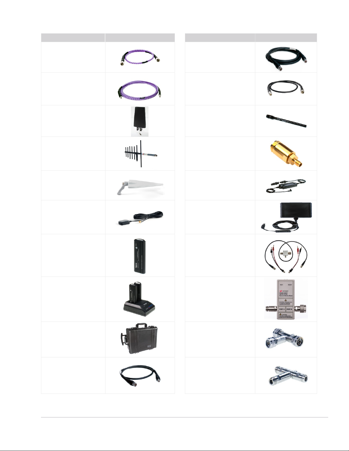
Description
Accessory
Description
Accessory
N9910X-701
Type-N (m) to Type-N (m)
cable, 3.28 ft
N9910X-812
Type-N (m) to Type-N (m) cable,
12 ft
N9910X-708
3.5 mm (m) to 3.5 mm (f)
cable, 3.28 ft
N9910X-816
Type-N (m) to Type-N (f) cable,
3.28 ft
N9910X-820
Antenna, directional
N9910X-821
Antenna, telescopic whip ™
N9910XA-823
Antenna, cellular narrowband
N9910X-848
Coaxial adapter, Type-N(f) to
3.5 mm (f)
N9910X-822
Antenna, directional
N9910X-875
DC car charger and adapter
N9910X-825
Antenna, GPS, active
N9910X-873
AD/DC adapter
N9910X-876
Extra high-capacity battery
N9910X-874
External bias-tee
N9910X-872
External battery charger
N4690B
2-port ECal, Type-N,
18 GHz
N9910X-881
Hard transit case
N9910X-800
3-in-1 OSL cal kit, Type-N (m),
6 GHz
N9910X-811
Type-N (m) to Type-N (f)
cable, 5 ft
N9910X-801
3-in-1 OSL cal kit, Type-N (f),
6 GHz
Page 26
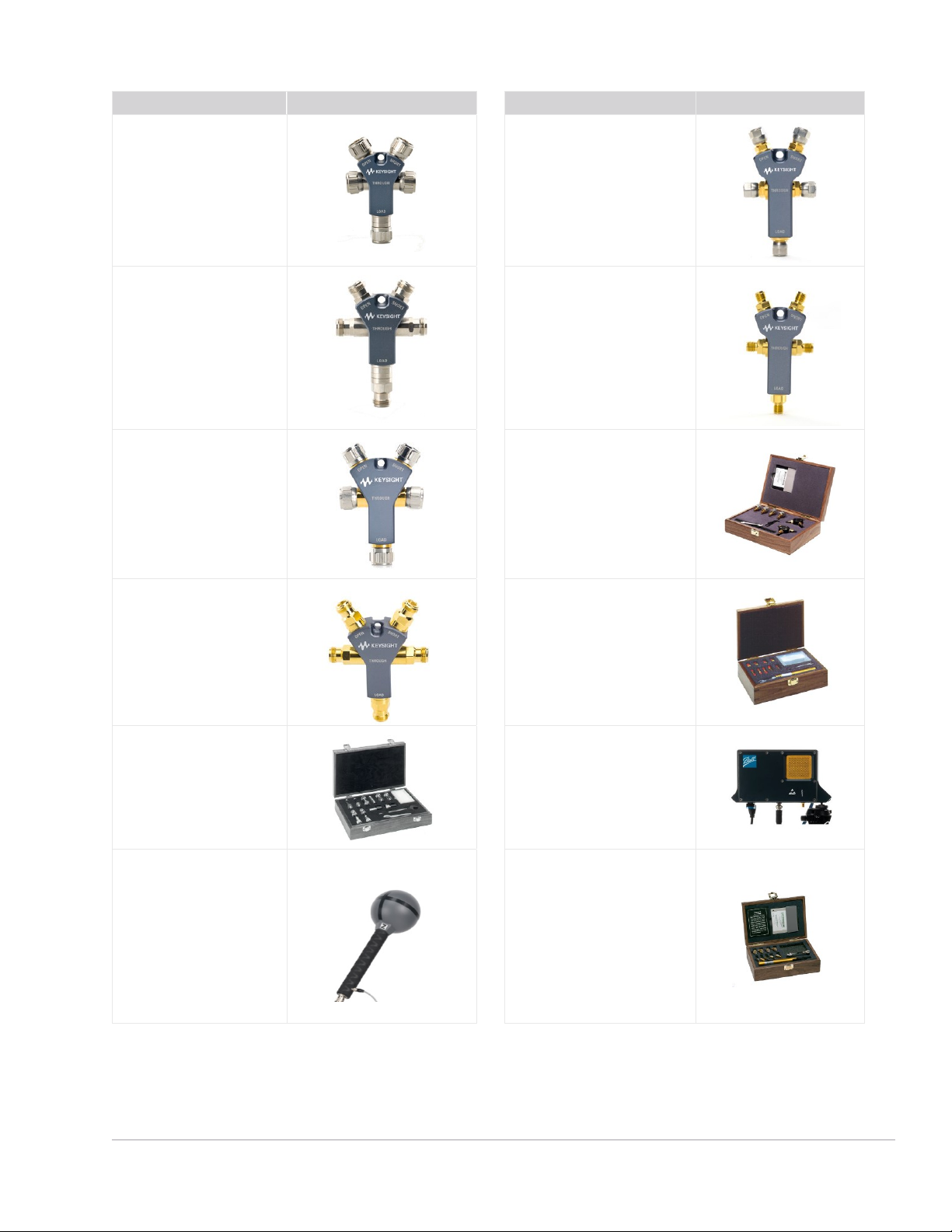
Fi nd us at www.keysight.com Pa ge 26
Description
Accessory
Description
Accessory
85514A
4-in-1 OSLT cal kit, Type-N
(m) 9 GHz
85520A
4-in-1 OSLT cal kit, 3.5 mm (m),
26.5 GHz
85515A
4-in-1 OSLT cal kit, Type-N (f),
9 GHz
85521A
4-in-1 OSLT cal kit, 3.5 mm (f),
26.5 GHz
85518A
4-in-1 OSLT cal kit, Type-N
(m), 18 GHz
85033D/E
3.5 mm cal kit, 9 GHz
85519A
4-in-1 OSLT cal kit, Type-N (f),
18 GHz
85052D
3.5 mm cal kit, 26.5 GHz
85054D
Economy cal kit, Type-N,
18 GHz
85571A-028 1
5G Phased Array Antenna
28 GHz
85572A-006
Triaxial Isotropic Antenna
(30 MHz to 6 GHz)
85056D
2.4 mm cal kit, 50 GHz
1
. This pr odu ct is c urren tly n ot Ro HS -c omp li ant.
Page 27
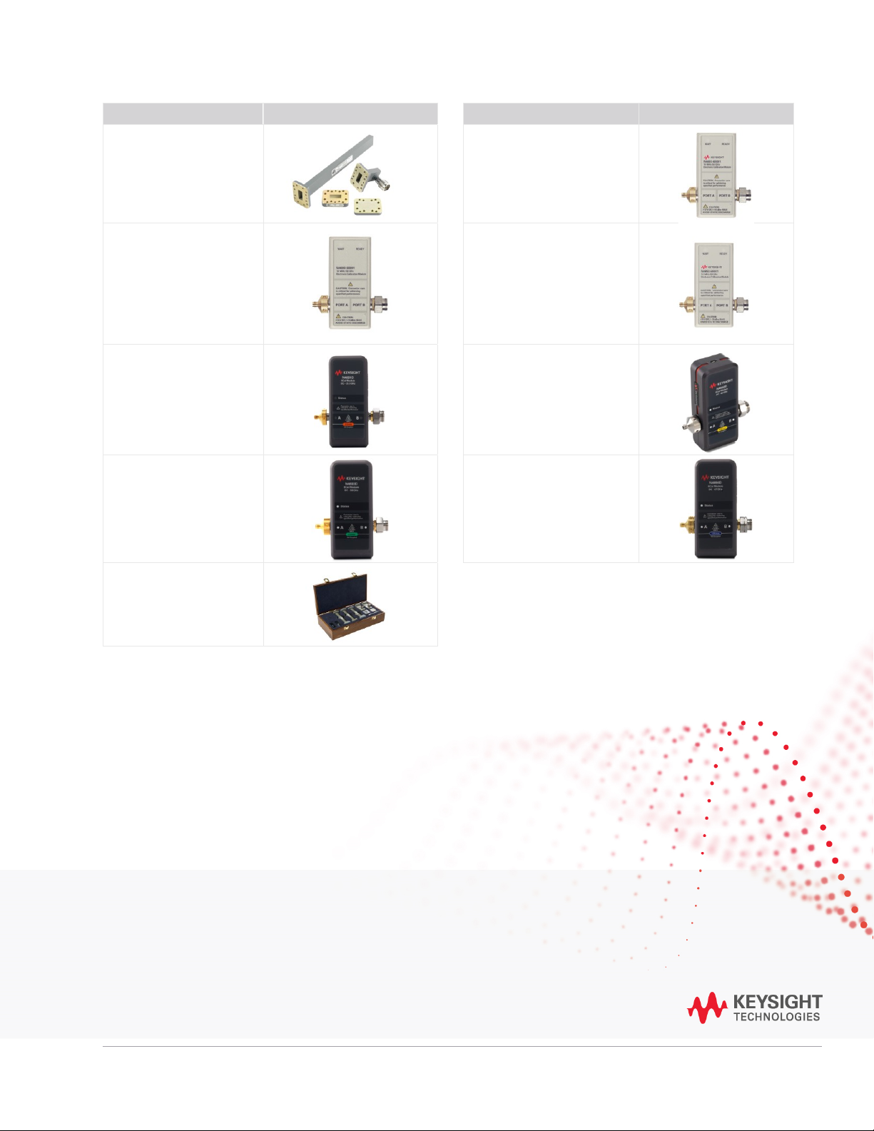
Fi nd us at www.keysight.com Pa ge 27
Thi s info rmatio n is subje ct to chang e with out no tice. © Key sight Techn ologi es, 2019 - 2021, Publ ished in US A, No vembe r 10, 2021, 5992-3701EN
Learn more at: www.keysight.com
For more information on Keysight Technologies’ products, applications or services,
please contact your local Keysight office. The complete list is available at:
www.keysight.com/find/contactus
Description
Accessory
Description
Accessory
N9911X-211/212/213/214
WR-90 economical cal kit
N4691B
1
3.5 mm, 2-port ECal, 26.5 GHz
N4692A
1
2.92 mm, 2-port ECal,
40 GHz
N4693A
1
2.4 mm 2-port ECal, 50 GHz
N4691D
3.5 mm, 2-port ECal, 26.5 GHz
N4692D
2.92 mm, 2-port ECal,
40 GHz
N4693D
2.4 mm, 2-port ECal, 50 GHz
N4694D
1.85 mm, 2-port ECal, 67 GHz
X11644A
WR-90 standard cal kit
1. Prod uc t i s disco ntinu ed .
 Loading...