


Keysight N9911X
Economical Waveguide
Calibration Components
Configuration
Guide


Notices
CAUTION
WARNING
© Keysight Technologies 2013, 2014
No part of this manual may be reproduced
in any form or by any means (including
electronic storage and retrieval or translation into a foreign language) without prior
agreement and written consent from Keysight Technologies as governed by United
States and international copyright laws.
Manual Part Number
N9911-90003
Edition
August 2014
Keysight Technologies
1400 Fountaingrove Parkway
Santa Rosa, CA 95403
Warranty
The material contained in this document is provided “as is,” and is subject to being changed, without notice,
in future editions. Further, to the maximum extent permitted by applicable
law, Keysight disclaims all warranties, either express or implied, with
regard to this manual and any information contained herein, including
but not limited to the implied warranties of merchantability and fitness for
a particular purpose. Keysight shall
not be liable for errors or for incidental or consequential damages in connection with the furnishing, use, or
performance of this document or of
any information contained herein.
Should Keysight and the user have a
separate written agreement with
warranty terms covering the material
in this document that conflict with
these terms, the warranty terms in
the separate agreement shall control.
Technology Licenses
The hardware and/or software described in
this document are furnished under a
license and may be used or copied only in
accordance with the terms of such license.
Restricted Rights Legend
52.227-19 (June 1987) or any equivalent
agency regulation or contract clause. Use,
duplication or disclosure of Software is
subject to Keysight Technologies’ standard
commercial license terms, and non-DOD
Departments and Agencies of the U.S. Government will receive no greater than
Restricted Rights as defined in FAR
52.227-19(c)(1-2) (June 1987). U.S. Government users will receive no greater than
Limited Rights as defined in FAR 52.227-14
(June 1987) or DFAR 252.227-7015 (b)(2)
(November 1995), as applicable in any
technical data.
Safety Notices
A CAUTION notice denotes a hazard. It calls attention to an operating procedure, practice, or the like
that, if not correctly performed or
adhered to, could result in damage
to the product or loss of important
data. Do not proceed beyond a
CAUTION notice until the indicated
conditions are fully understood and
met.
A WARNING notice denotes a
hazard. It calls attention to an
operating procedure, practice, or
the like that, if not correctly performed or adhered to, could result
in personal injury or death. Do not
proceed beyond a WARNING
notice until the indicated conditions are fully understood and met.
If software is for use in the performance of
a U.S. Government prime contract or subcontract, Software is delivered and
licensed as “Commercial computer software” as defined in DFAR 252.227-7014
(June 1995), or as a “commercial item” as
defined in FAR 2.101(a) or as “Restricted
computer software” as defined in FAR

N9911X Economical Waveguide Calibration Components
N9911X Economical Waveguide Calibration Components are used to calibrate Keysight FieldFox Handheld
Analyzers. These components are purchased separately — it is not necessary to buy a kit. This allows you to
purchase only the components you need, saving the expense of non-necessary components and a storage
box.
Use the following information to help determine which N9911X Economical Waveguide Calibration
Components to purchase.
Types of Calibration Components
Here is a brief explanation of the types of calibration components that you can purchase. Refer to
“Calibration Component Part Numbers and Photos” on page 3 to see images of the components.
Adapter, Waveguide-to-Coax
The adapter is intended for adapting the analyzer’s coaxial connectors to waveguide flanges.
Te r mi n a ti o n
A termination is also called a load. It is connected directly to the adapter.
¼ Wavelength Offset Shim
A ¼ wavelength offset shim is also called a ¼ wavelength section. The shim is connected between the
adapter and the short to create an offset short.
Short
A short is also called a flush short. It is connected directly to the adapter, or used as an offset short when
combined with the ¼ wavelength offset shim.
Coax Cables
To perform a 1-port calibration, one coaxial cable is required. To perform a 2-port calibration, two coaxial
cables are required. Each cable is connected between an analyzer test port and a waveguide-to-coax
adapter. A list of Keysight cables available for purchase is in the “Accessories” section of the online
document Keysight FieldFox Handheld Analyzers Configuration Guide (part number 5990-9836EN).
Coupling Set (Hardware) for Flanges
Hardware items such as screws, nuts, washers, and slip pins are necessary for coupling flanges together.
One coupling set (english/imperial or metric) contains all of the flange hardware you need for performing
both 1-port and 2-port calibrations. It is not necessary to buy more than one coupling set.
Configuration Guide N9911-90003 1

Purchasing Calibration Components and Hardware
1. Keysight N9911X Economical Waveguide Calibration Components can be purchased with
english/imperial or metric threads. If you already own other Keysight waveguide calibration
components, be aware that these have metric threads, so you should order N9911X metric components
rather than english/imperial components for full compatibility.
2. To perform a 1-port calibration, you need the following calibration components and hardware. Refer to
the tables in “Calibration Component Part Numbers and Photos” on page 3 for part number information.
• Adapter, qty 1
• Termination, qty 1
• Flush short, qty 1
• 1/4 wavelength offset shim, qty 1
• Coax cable, qty 1 (refer to “Coax Cables” on page 1)
• Coupling set, qty 1 (refer to “Coupling Set (Hardware) for Flanges” on page 1)
3. To perform a 2-port calibration, you need the following calibration components and hardware. Refer to
the tables in “Calibration Component Part Numbers and Photos” on page 3 for part number information.
• Adapter, qty 2
• Termination, qty 1
• Flush short, qty 1
• 1/4 wavelength offset shim, qty 1
• Coax cable, qty 2 (refer to “Coax Cables” on page 1)
• Coupling set, qty 1 (refer to “Coupling Set (Hardware) for Flanges” on page 1)
4. Purchase the N9911X Economical Waveguide Calibration Components and hardware by contacting
Keysight on the Web at: www.keysight.com/find/assist.
2 Configuration Guide N9911-90003

Calibration Component Part Numbers and Photos
The tables on the following pages list the part numbers and descriptions for the N9911X Economical
Waveguide Calibration Components. The figures on the following pages show photos of the components.
Table 1 Calibration Components with Waveguide Designators C-Band/WR137/WG14, 5.38 – 8.18 GHz
Description Keysight
Option Number
Calibration Grade Components – Metric
Adapter, WR137 waveguide to type-N (male) coax
Termination
Flush short
¼ wavelength offset shim
Coupling set for flange
(screw, M5 X 30, qty 16; bolt, M5 X 22 X 12, qty 6; bolt, M5 X
30 X 18.5, qty 8; screw, M5 X 45, qty 8; nut, M5, qty 16;
washer, M5, qty 32; slip pin, Ø1/8” X 15 mm, qty 4)
Calibration Grade Components – English (Imperial)
Adapter, WR137 waveguide to type-N (male) coax
Termination
Flush short
¼ wavelength offset shim
Coupling set for flange
(screw, #10-32 UNF X 1 1/4”, qty 16; screw, #10-32 UNF X 1
3/4”, qty 8; screw, #10-32 UNF X 1”, qty 8; nut, #10-32 UNF,
qty 16; washer, M5, qty 32; slip pin, Ø1/8” X 15 mm, qty 4)
N9911X
N9911X
N9911X
N9911X
N9911X
N9911X
N9911X
N9911X
N9911X
N9911X
–110
–111
–112
–113
–114
–115
–116
–117
–118
–119
Configuration Guide N9911-90003 3

Figure 1 Calibration Components with Waveguide Designators C-Band/WR137/WG14, 5.38 – 8.18
GHz
4 Configuration Guide N9911-90003

Table 2 Calibration Components with Waveguide Designators X-Band/WR90/WG16, 8.2 – 12.5 GHz
Description Keysight
Option Number
Calibration Grade Components – Metric
Adapter, WR90 waveguide to type-N (male) coax
Termination
Flush short
¼ wavelength offset shim
Coupling set for flange
(screw, M4 X 25, qty 16; screw, M4 X 30, qty 8; bolt, M4 X 21 X
12 (4.0), qty 8; bolt, M4 X 18 X 9 (4.17), qty 4; nut, M4, qty 16;
washer, M4, qty 32; slip pin, Ø1/8” X 15 mm, qty 4)
Calibration Grade Components – English (Imperial)
Adapter, WR90 waveguide to type-N (male) coax
Termination
Flush short
¼ wavelength offset shim
Coupling set for flange
(screw, #8-32-UNC X 1”, qty 16; screw, #8-32 UNC X 1 1/4”,
qty 8; screw, #8-32 UNC X 3/4”, qty 8; nut, #8-32 UNC, qty
16; washer, #8, qty 32; slip pin, Ø1/8” X 15 mm, qty 4)
N9911X
N9911X
N9911X
N9911X
N9911X
N9911X
N9911X
N9911X
N9911X
N9911X
–210
–211
–212
–213
–214
–215
–216
–217
–218
–219
Configuration Guide N9911-90003 5

Figure 2 Calibration Components with Waveguide Designators X-Band/WR90/WG16, 8.2 – 12.5
GHz
6 Configuration Guide N9911-90003

Table 3 Calibration Components with Waveguide Designators Ku-Band/WR62/WG18, 11.9 – 18 GHz
Description Keysight
Part Number
Calibration Grade Components – Metric
Adapter, WR62 waveguide to Type-N (male) coax
Termination
Flush short
¼ wavelength offset shim
Coupling set for flange
(screw, M4 X 25, qty 12; screw, M4 X 30, qty 6; bolt, M4 X 21 X
12 (4.0), qty 6; bolt, M4 x 18 x 9 (4.0), qty 4; nut, M4, qty 12;
washer, M4, qty 24; slip pin, Ø1/8” X 15 mm, qty 4)
Calibration Grade Components – English (Imperial)
Adapter, WR62 waveguide to Type-N (male) coax
Termination
Flush short
¼ wavelength offset shim
Coupling set for flange
(screw, #6-32-UNC X 1”, qty 8; screw, #6-32-UNC X 1 1/4”,
qty 4; screw, #6-32 UNC X 5/8”, qty 4; nut, #6-32 UNC, qty 8;
washer, #6, qty 16; slip pin, Ø1/8” X 15 mm, qty 4)
N9911X
N9911X
N9911X
N9911X
N9911X
N9911X
N9911X
N9911X
N9911X
N9911X
–310
–311
–312
–313
–314
–315
–316
–317
–318
–319
Configuration Guide N9911-90003 7
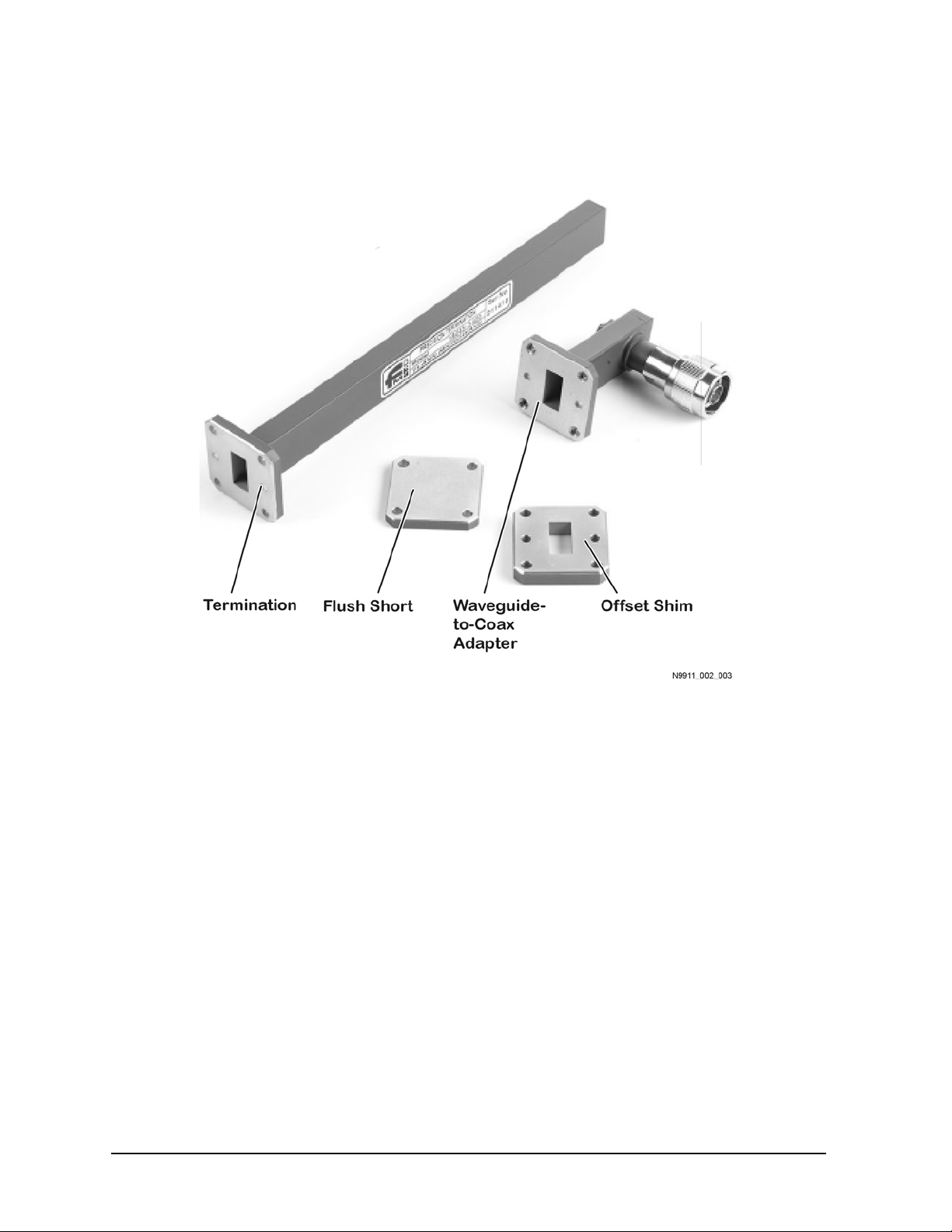
Figure 3 Calibration Components with Waveguide Designators Ku-Band/WR62/WG18, 11.9 – 18
GHz
8 Configuration Guide N9911-90003

Table 4 Calibration Components with Waveguide Designators K-Band/WR42/WG20, 17.6 – 26.7 GHz
Description Keysight
Part Number
Calibration Grade Components – Metric
Adapter, WR42 waveguide to 3.5 mm (male) coax
Termination
Flush short
¼ wavelength offset shim
Coupling set for flange
(screw, M3 X 20, qty 12; screw, M3 X 25, qty 6; bolt, M3 X 19 X
12.5, qty 6; bolt, M3 X 16 X 10, qty 4; nut, M3, qty 12; washer,
M3, qty 24; slip pin, Ø3/32” X 12 mm, qty 4)
Calibration Grade Components – English (Imperial)
Adapter, WR 42 waveguide to 3.5 mm (male) coax
Termination
Flush short
¼ wavelength offset shim
Coupling set for flange
(screw, #4-40-UNC X 3/4”, qty 8; screw, #4-40 UNX X 1”, qty
4; screw, #4-40 UNX X 5/8”, qty 4; nut, #4-40 UNC, qty 8;
washer, #4, qty 16; slip pin, Ø3/32” X 12 mm, qty 4)
N9911X
N9911X
N9911X
N9911X
N9911X
N9911X
N9911X
N9911X
N9911X
N9911X
–410
–411
–412
–413
–414
–415
–416
–417
–418
–419
Configuration Guide N9911-90003 9

10 Configuration Gu ide N9911-90003

This information is subject to change without notice.
© Keysight Technologies 2013, 2014
August 2014
*N9911-90003*
N9911-90003
www.keysight.com
 Loading...