

Page 1

Keysight N9320B
Spectrum Analyzer
Programmer’s Guide
Page 2

Notices
© Keysight Technologies,
Inc. 2008-2019
No part of this manual may be
reproduced in any form or by any
means (including electronic storage
and retrieval or translation into a
foreign language) without prior
agreement and written consent from
Keysight Technologies, Inc. as
governed by United States and
international copyright laws.
Trademark Acknowledgments
Manual Part Number
N9320-90029
Edition
Edition 5, December 2018
Available in electronic format only
Published by:
Keysight Technologies
No 116 Tianfu 4th street
Chengdu, 610041, China
Warranty
THE MATERIAL CONTAINED IN THIS
DOCUMENT IS PROVIDED “AS IS,”
AND IS SUBJECT TO BEING
CHANGED, WITHOUT NOTICE, IN
FUTURE EDITIONS. FURTHER, TO
THE MAXIMUM EXTENT PERMITTED
BY APPLICABLE LAW, KEYSIGHT
DISCLAIMS ALL WARRANTIES,
EITHER EXPRESS OR IMPLIED WITH
REGARD TO THIS MANUAL AND
ANY INFORMATION CONTAINED
HEREIN, INCLUDING BUT NOT
LIMITED TO THE IMPLIED
WARRANTIES OF
MERCHANTABILITY AND FITNESS
FOR A PARTICULAR PURPOSE.
KEYSIGHT SHALL NOT BE LIABLE
FOR ERRORS OR FOR INCIDENTAL
OR CONSEQUENTIAL DAMAGES IN
CONNECTION WITH THE
FURNISHING, USE, OR
PERFORMANCE OF THIS
DOCUMENT OR ANY INFORMATION
CONTAINED HEREIN. SHOULD
KEYSIGHT AND THE USER HAVE A
SEPARATE WRITTEN AGREEMENT
WITH WARRANTY TERMS
COVERING THE MATERIAL IN THIS
DOCUMENT THAT CONFLICT WITH
THESE TERMS, THE WARRANTY
TERMS IN THE SEPARATE
AGREEMENT WILL CONTROL.
Technology Licenses
The hardware and/or software
described in this document are
furnished under a license and may be
used or copied only in accordance
with the terms of such license.
U.S. Government Rights
The Software is “commercial
computer software,” as defined
by Federal Acquisition Regulation
(“FAR”) 2.101. Pursuant to FAR
12.212 and 27.405-3 and
Department of Defense FAR
Supplement (“DFARS”) 227.7202,
the U.S. government acquires
commercial computer software
under the same terms by which
the software is customarily
provided to the public.
Accordingly, Keysight provides
the Software to U.S. government
customers under its standard
commercial license, which is
embodied in its End User License
Agreement (EULA), a copy of
which can be found at
http://www.keysight.com/find/sweula
The license set forth in the EULA
represents the exclusive authority
by which the U.S. government
may use, modify, distribute, or
disclose the Software. The EULA
and the license set forth therein,
does not require or permit,
among other things, that
Keysight: (1) Furnish technical
information related to
commercial computer software
or commercial computer
software documentation that is
not customarily provided to the
public; or (2) Relinquish to, or
otherwise provide, the
government rights in excess of
these rights customarily provided
to the public to use, modify,
reproduce, release, perform,
display, or disclose commercial
computer software or
commercial computer software
documentation. No additional
government requirements
beyond those set forth in the
EULA shall apply, except to the
extent that those terms, rights, or
licenses are explicitly required
from all providers of commercial
computer software pursuant to
the FAR and the DFARS and are
set forth specifically in writing
elsewhere in the EULA. Keysight
shall be under no obligation to
update, revise or otherwise
modify the Software. With
respect to any technical data as
defined by FAR 2.101, pursuant
to FAR 12.211 and 27.404.2 and
DFARS 227.7102, the U.S.
government acquires no greater
than Limited Rights as defined in
FAR 27.401 or DFAR 227.7103-5
(c), as applicable in any technical
data.
Safety Notices
A CAUTION notice denotes a hazard. It
calls attention to an operating
procedure, practice, or the like that,
if not correctly performed or adhered
to, could result in damage to the
product or loss of important data. Do
not proceed beyond a CAUTION
notice until the indicated conditions
are fully understood and met.
A WARNING notice denotes a hazard.
It calls attention to an operating
procedure, practice, or the like that,
if not correctly performed or adhered
to, could result in personal injury or
death. Do not proceed beyond a
WARNING notice until the indicated
conditions are fully understood and
met.
Page 3

Getting Started 1
Remotely Operating Your N9320B 2
Computer Requirement for Remote Operation 2
Connecting the N9320B to a PC via the USB Port 3
Connecting the N9320B to a PC via the LAN Port 6
Using Socket to Send Commands 8
Using Telnet to Send Commands 10
Programming Fundamentals 13
Overview 14
SCPI Language Basics 14
Command Categories 16
Command Syntax 17
Command Statement Rules Overview 18
Command Example 18
Creating Valid Commands 19
Contents
Program and Response Messages 20
Parameters in Commands 21
Boolean 21
Key Word 21
Units 21
Variable 21
Status Registers 23
Overview 24
What are Status Registers 24
iii
Page 4

Contents
What are Status Register SCPI Commands 25
How to use the Status Registers 26
Status Register Examples 27
Status Register System 28
Setting and Querying the Status Register 29
The Status Byte Register 30
Standard Event Status Register 32
STATus:OPERation Ragister 34
STATus:OPERation Condition and Event Enable Registers 36
STATus:QUEStionable:INTegrity Registers 37
Programming Example 39
Overview 40
Programming in C using the VTL 41
Typical Example Program Contents 41
Example Program 42
Including the VISA Declarations File 43
Opening a Session 44
Device Sessions 44
Addressing a Session 46
Closing a Session 46
Checking USB Connection 47
Using C with Marker Peak Search and Peak Excursion 48
Using Marker Delta Mode and Marker Minimum Search 52
Measuring Phase Noise 56
Command Reference 59
IEEE Common Commands 60
CALCulate Subsystem 64
CALCulate:LLINe Subsection 66
iv
Page 5

CALCulate:MARKer Subsection 70
CALCulate:NTData Subsection 81
CALibration Subsystem 82
CONFigure Subsystem 84
DANalyse Subsystem 86
DANalyse:AM/FM Subsection 88
DANalyse:ASK/FSK Subsection 95
Demod Subsystem 102
DISPlay Subsystem 103
FETCh Subsystem 108
INITiate Subsystem 111
MMEMory Subsystem 113
OUTPut Subsystem 117
READ Subsystem 118
Contents
SENSe Subsystem 122
[:SENSe]:ACPower Subsection 122
[:SENSe]:CHPower Subsection 127
[:SENSe]:CORRection Subsection 129
[:SENSe]:DEMod Subsection 130
[:SENSe]:OBWidth Subsection 131
[:SENSe]:TOI Subsection 134
[:SENSe]:SEMask Subsection 136
[:SENSe]:AVERage Subsection 143
[:SENSe]:BANDwidth Subsection 145
[:SENSe]:DETector Subsection 147
[:SENSe]:FREQuency Subsection 148
[:SENSe]:POWer Subsection 150
v
Page 6

Contents
[:SENSe]:SWEep Subsection 152
SOURce Subsystem 153
STATus Subsystem 156
STATus:QUEStionable:INTegrity Subsection 157
SYSTem Subsystem 158
TRACe Subsystem 163
TRIGger Subsystem 166
UNIT Subsystem 169
vi
Page 7

Getting Started
1 Getting Started
The purpose of this chapter is to serve as a reminder of SCPI (Standard
Commands for Programmable Instruments) fundamentals to those who have
previous experience in programming SCPI. This chapter is not intended to
teach you everything about the SCPI programming language. If you are using
an optional programming compatibility modes, you should refer to the manual
that came with the option.
1
Page 8

Getting Started
Remotely Operating Your N9320B
Remotely Operating Your N9320B
The signal generator provides USB and LAN connections and
allows you to set up a remote operation environment via the
USB/LAN interface with a controller computer.
Computer Requirement for Remote Operation
Usually, you need to prepare an compatible PC with the following
requirements to set up a remote operation environment:
Processor: 450 MHz Pentium
Operating system: Microsoft
Service Pack 1 or later; Windows
4 or later
Available memory: 128 MB or higher required
Available disk space: 175 MB or greater required
® II or higher required
® Windows® XP or Home Editon,
® 2000 Professional, service pack
2
Page 9
Getting Started
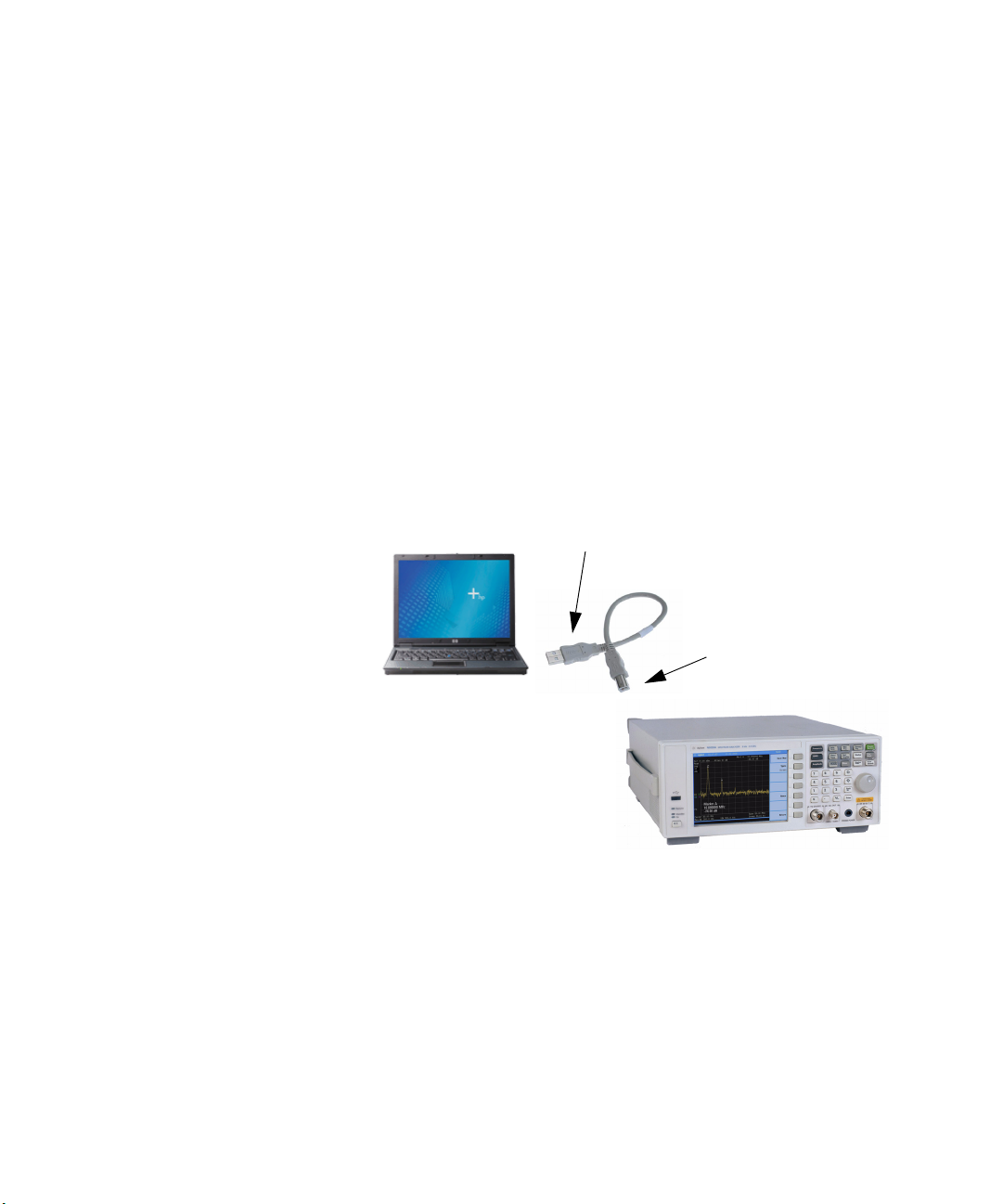
Connecting instrument
Connecting PC
Remotely Operating Your N9320B
Connecting the N9320B to a PC via the USB Port
No extra driver is required to connect the N9320B via the USB port
to a PC. All you need is the keysight IO libraries suite and you can
find this IO libraries suite in the documentation CD in the shipment
along with your N9320B. Or download the IO libraries suite from
Keysight website:
http://www.keysight.com/find/iolib
Refer to the following steps to finish the connection:
1 Install Keysight IO libraries suite
2 Switch on the N9320B
3 Connect the analyzer to a PC with a USB cable.
3
Page 10
Getting Started
Remotely Operating Your N9320B
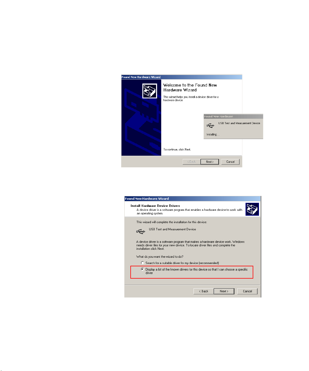
4 After a while, the PC finds your N9320B as a new hardware and
prompts a message saying “Found new hardware...”. A Found New
Hardware Wizard is initiated immediately.
5 Select Display a list...
4
Page 11
Getting Started
Remotely Operating Your N9320B
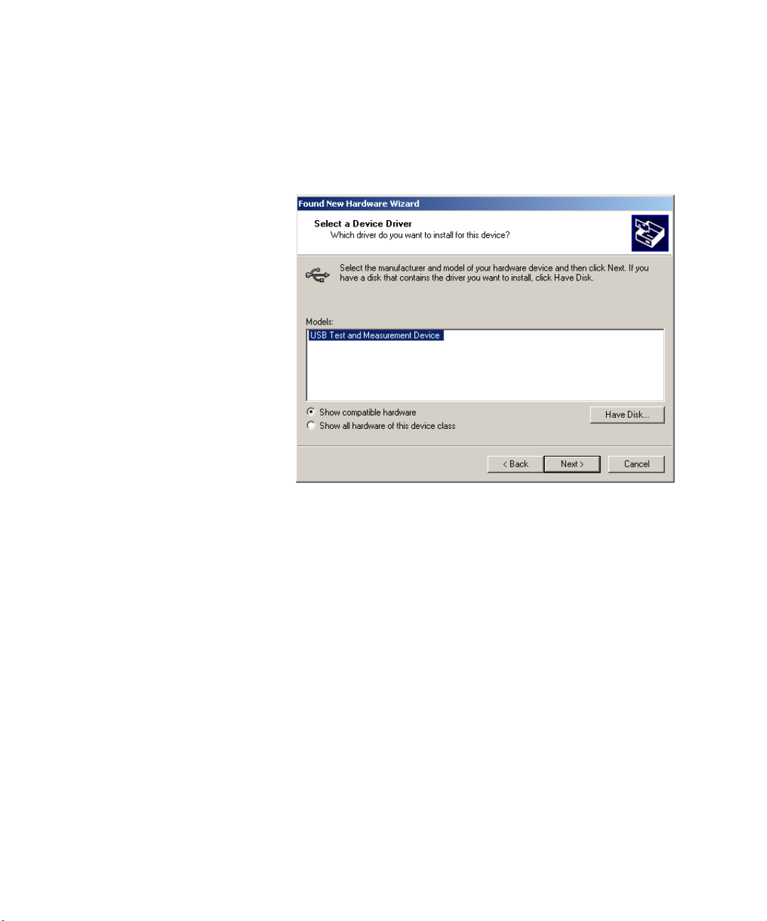
7 PC will detect the instrument automatically. The item “USB Test
and Measurement Device” displays in the pop-up window. Select it
and press Next.
8 The wizard will guide you through the rest of installation till the
driver is installed.
9 Run Keysight IO libraries suite, the N9320B will be detected
automatically. If not, press Refresh All.
5
Page 12
Getting Started
Remotely Operating Your N9320B
Connecting the N9320B to a PC via the LAN Port
No extra driver is required to connect the N9320B via the LAN port
to a PC. All you need is the Keysight IO libraries suite and you can
find this IO libraries suite in the Product CD N9320B Help Kit in the
shipment. Or download the IO libraries suite from the website:
http://www.keysight.com/find/iolib
Please refer to the following steps to finish the connection:
1 Switch on the analyzer.
2 Connect the spectrum analyzer to a PC with a LAN cable.
3 Press [Preset/System] > {More} > {More} > {IP Admin} > {IP
address} to set IP address for the instrument. For example, set
“10.0.0.5” as the IP address for the instrument.
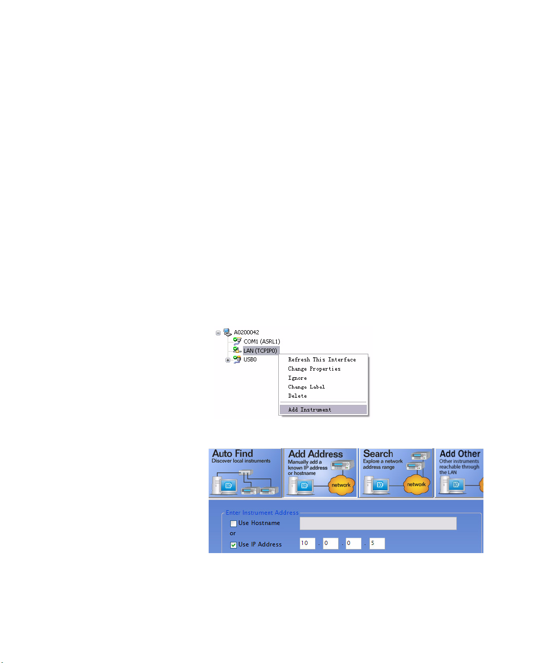
4 Run Keysight Connection Expert in IO libraries suite. Right-click on
the LAN (TCPIP0) icon, select “Add Instrument’ in the pop-up
menu. The “Add LAN Instruments” window displays for the IP
configuration.
5 Select “Add Address”, check “Use IP Address” in the window and
input the IP address as the instrument IP address you set before.
6
Page 13
Getting Started
Remotely Operating Your N9320B
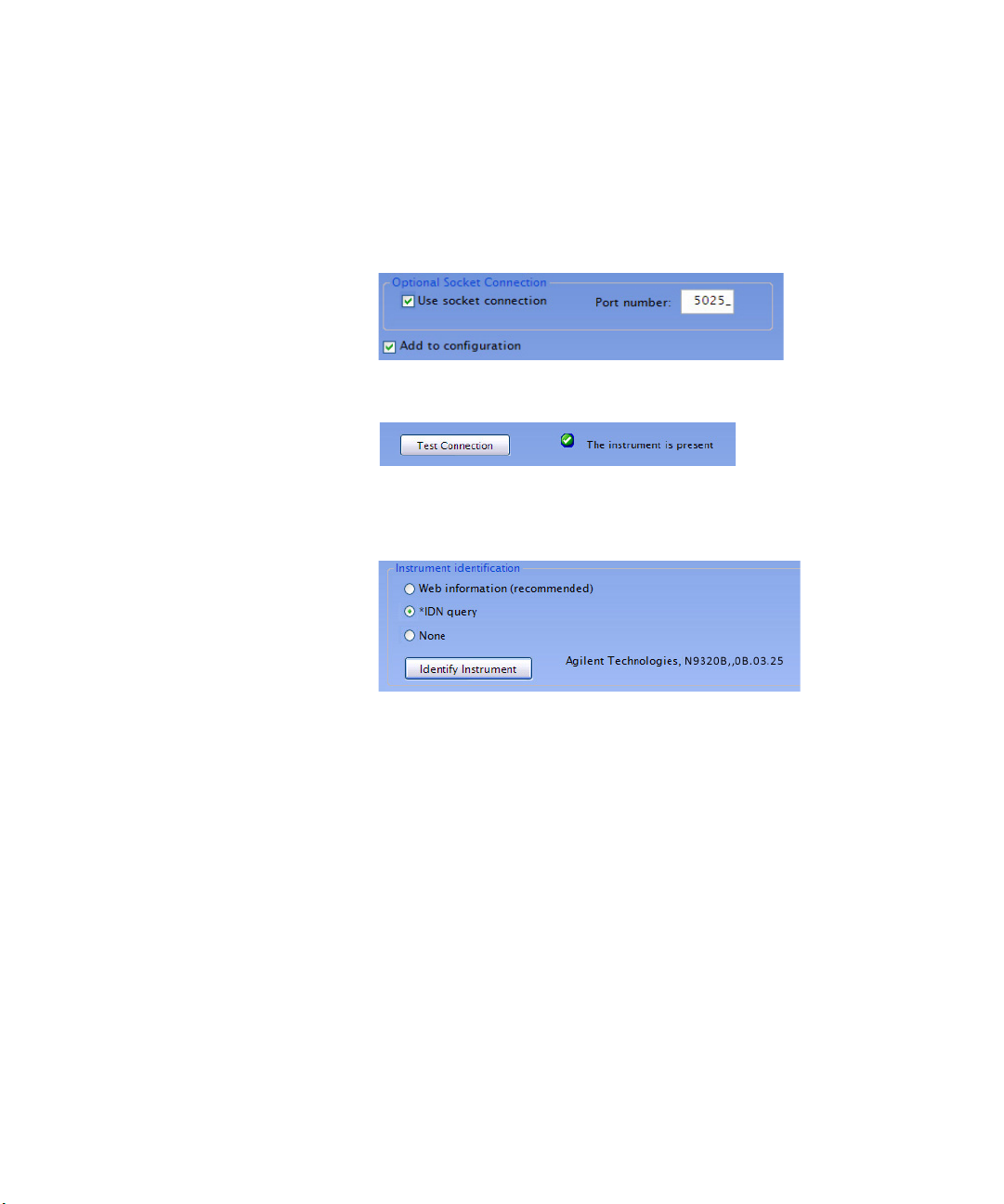
6 Check “Use socket connection” if you want to use socket to send
commands. Or you can ignore this step and leave the Use socket
connection box unchecked. The socket port number is default to
5025. Please refer to the ”Using Socket to Send Commands“ on
page 8 for further information on socket programming
7 Press “Test Connection” to check the LAN connection. The figure
below indicates that the connection is ready.
8 Check “*IDN query” and press “Identify Instrument”. The
instrument information shows the firmware revision and product
number. The analyzer is ready for your further programming..
7
Page 14

Getting Started
Remotely Operating Your N9320B
Using Socket to Send Commands
N9320B implements a socket Applications Programming Interface
(API) compatible with Berkeley sockets, Winsock, and other
standard sockets APIs. You can use sockets to control N9320B by
sending SCPI commands to a socket connection. You can program
by only the socket function or the VISA function. Both the VISA
assistant and the IO libraries suite is available for remote control.
Please refer to the following C# programming example to use the
socket calss function.
private IPAddress serveraddrSA; //define the tcp
server
public TcpClient clientSA; //define the tcp
client
/*initiate the server and client and create the
connection*/
private void InitialSA(string ip, int port)
{
serveraddrSA = IPAddress.Parse(ip);
clientSA = new TcpClient();
clientSA.Connect(serveraddrSA, port);
}
/*send the SCPI to instrument, MUST add end flag
at the end of the command*/
private void SendSA(string cmd)
{
string endchar = "\n" ;
clientSA.Client.Send(System.Text.Encoding.Default.Get
Bytes(cmd+endchar));
}
/*send the read SCPI to instrument, MUST add end flag
at the end of the command, and then return the
result*/
private string ReadSA(string cmd)
{
int bytes = 0;
Byte[] RecvBytes = new Byte[8192];
string endchar = "\n";
SendSA(cmd+endchar);
bytes = clientSA.Client.Receive(RecvBytes,
RecvBytes.Length, 0);
8
Page 15

Getting Started
NOTE
Remotely Operating Your N9320B
return Encoding.ASCII.GetString(RecvBytes,
0, bytes);
}
/*close the server and client connection */
private void SAClose()
{
clientSA.Close();
}
/*simple test program*/
Public void test()
{
InitialSA("192.168.0.111", 5025);
SendSA("*RST");
SendSA(":FREQuency:SPAN 100mhz");
String result=ReadSA("*IDN?");
SAClose();
}
N9320B supports serveral end flag in programming, such as '\r', '\r\n', '\n', '\
n\r'. please maker sure use the listed end flag in the program.
9
Page 16
Getting Started
NOTE
NOTE
Remotely Operating Your N9320B
Using Telnet to Send Commands
N9320B provides the telnet programming function in Windows. It
allows the programmer send or receive information by SCPI commands.
The syntax of the telnet command is:
Establish connection:
Send Command: SCPI> KM2 SCPI command
The maximum connections N9320B allowed at one time is 5 connections.
Attempt to setup more connections will be refused.
Please refer to the procedures below to use this function based on
LAN connection.
1 Click Start > Run in windows system on your PC. Eenter "cmd" to
open the command pop-up window and then type the telnet
command to setup a telnet connection.
2 Type remote commands after the prompt SCPI>, and then press
enter key to send them to the device. Commands typed must
accord with requirments of SCPI.
telnet <IP address> <Port number>
Please find the Telnet example as below:
Welcome to Telnet SCPI Server: N9320B
Keysight Technologies,N9320B,
A.01.01.CIDKMNEW,0B.03.03
SCPI>calc:mark:mode pos
SCPI>calc:mark:max
SCPI>calc:mark:x?
+2.5000000000000000E+009
SCPI> calc:mark:mode pos; :calc:mark:max
SCPI>
10
Page 17

Getting Started
Remotely Operating Your N9320B
the script is also allowed in the telnet programming. Please find the
script example as below:
set sh=WScript.CreateObject("WScript.Shell")
sh.run "telnet 146.208.209.171 5025"
WScript.Sleep 300
sh.SendKeys ":init:cont off;:freq:center 582.057
MHz;:freq:span 3000 Hz;:band:RES 30 Hz"
sh.SendKeys "{ENTER}"
WScript.Sleep 300
sh.SendKeys ":freq:center?"
sh.SendKeys "{ENTER}"
Please follow the steps below to use this script example in telnet
programming:
1. Copy these commands above to a new txt file
2. Replace the IP address, port number and the command you
need.
3. After you finish the editing, save the file with subfix vbs, such as
script.vbs.
4. Double click this file in Operating system or type the file name
and press ENTER in command window to run this program. The
program will be initiated immediately and the result will be return
in command window.
11
Page 18

Getting Started
Remotely Operating Your N9320B
Special telnet character
N9320B provides some combination keys as special telnet
cahracter. Please refer to the lis as below:
Ctrl+c Enter this character to clear the device registers. The
device registers would be cleared and <Device Clear> will be
returned.
Ctrl+d Enter this character to close the telnet connection. The
telnet connection will be closed and Connection lost will be
returned.
Ctrl+] When you are ready to close the telnet connection, enter
this character and get the telnet prompt. At the telnet prompt, type
quit or close. The telnet connection will be and Connection
closed will be displayed.
12
Page 19

Programming Fundamentals
2 Programming Fundamentals
The purpose of this chapter is to serve as a reminder of SCPI (Standard
Commands for Programmable Instruments) fundamentals to those who have
previous experience in programming SCPI. This chapter is not intended to
teach you everything about the SCPI programming language. If you are using
an optional programming compatibility modes, you should refer to the manual
that came with the option.
13
Page 20

Programming Fundamentals
Overview
Overview
SCPI Language Basics
This section is not intended to teach you everything about the SCPI
(Standard Commands for Programmable Instruments)
programming language. The SCPI Consortium or IEEE provides
that level of detailed information.
Programming with SCPI requires knowledge of:
• Computer programming languages, such as C, C++, and
MicrosoftâVisual Basicâ.
• The language of your instrument. The N9320B employs SCPI as
its programming language.
The semantic requirements of your controller’s language determine
how the programming commands and responses are handled in
your application program.
14
SCPI is an ASCII-based instrument command language designed
for test and measurement instruments, with the goal of reducing
automatic test equipment (ATE) program development time.
SCPI accomplishes this goal by providing a consistent
programming environment for instrument control and data usage.
This consistent programming environment is achieved by the use of
defined program messages, instrument responses, and data
formats across all SCPI instruments.
By providing a consistent programming environment, replacing one
SCPI instrument with another SCPI instrument in a system will
usually require less effort than with non-SCPI instrument.
SCPI is not a standard which completely provides for
interchangeable instrumentation. SCPI helps move toward
interchangeability by defining instrument commands and
responses, but not functionality, accuracy, resolution, etc.
Page 21

Common Terms used in this Book
Programming Fundamentals
Overview
Terms
Controller
Instrument
Command
Query
Description
Any computer used to communicate with an instrument. A controller can be a personal
computer (PC), a minicomputer, or a plug-in card in a card cage. Some intelligent
instruments can also function as controllers.
Any device that implements SCPI. Most instruments are electronic measurement or
stimulus devices, but this is not a requirement. Similarly, most instruments use a GPIB or
RS-232 or USB interface for communication. The same concepts apply regardless of the
instrument function or the type of interface used.
An instruction. You combine commands to form messages that control instruments to
complete a specified task. In general, a command consists of mnemonics (keywords),
parameters and punctuation.
A special type of command. Queries instruct the instrument to make response data
available to the controller. Query keywords always end with a question mark, ? .
The SCPI Consortium or IEEE can provide detailed information on
the subject of SCPI programming. Refer to IEEE Standard
488.1-1987, IEEE Standard Digital Interface for Programmable
Instrumentation. New York, NY, 1987, or to IEEE Standard
488.2-1992, IEEE Standard Codes, Formats, Protocols and
Common Commands for Use with ANSI/IEEE Std 488.1-1987. New
York, NY, 1992.
15
Page 22

Programming Fundamentals
Command Categories
Command Categories
The SCPI command falls into two categories:
• Subsystem commands that simulate front panel keystrokes
• Common commands that are unique and have no front panel
Use a computer to control the instrument (but operate the
power/standby switch manually). Computer programming
procedures for the instrument involve selecting a programming
statement and then adding the specified programming codes to
that statement to achieve the desired operating conditions.
equivalent
For more specific command instructions, please refer to
Command Reference, on page 59
.
16
Page 23

Command Syntax
Programming Fundamentals
Command Syntax
A command consists of mnemonics (keywords), parameters and
punctuation. Before you start to program your signal generator,
familiarize yourself with the standard notation of each of them.
Command
Mnemonics
(keywords)
Punctuation • A vertical bar "|" dictates a choice of one element from a list. For example: <A>|<B>
Separator • A colon ":" seperates keywords of different levels. The colon before the root
Many commands have both a long and a short form: use either one. (a combination of
the two is not allowed). Consider the :FREQuency command for example:
• Short form :FREQ
• Long form :FREQUENCY
SCPI is not case sensitive, so fREquEncy is just as valid as FREQUENCY, but FREQ and
FREQUENCY are the only valid forms of the FREQuency command.
In this documentation, upper case letters indicate the short form of the keyword. The
lower case letters indicate the long form of the keyword.
indicates that either A or B can be selected, but not both.
• Square brackets "[ ]" indicates that the enclosed items are optional.
• Angle brackets "< >" indicates a variable items to be entered to represent user
choices.
• A question mark "?" after a subsystem command indicates that the command is a
query. The returned information, <value> varies in format according to the type of
the field.
keyword is usually omitted.
• A space separates a keyword and a parameter, as well as a parameter and a unit.
17
Page 24

Programming Fundamentals
NOTE
Command Syntax
Command Statement Rules Overview
Command Example
Besides the standard notation of SCPI described above, please
remember the following rules in programming:
• command statements read from left to right
• use either long form or short form of keywords, but do not use
both
• no separating space between the keywords, only use a colon to
separate keywords of different levels
• always separating a keyword from a variable with a space
• always separating a variable from its unit with a space (if
variable has a unit).
A typical command is made up of key words set off by colons. The
key words are followed by parameters that can be followed by
optional units.
Example 1 :TRIGger:SEQuence:VIDeo:LEVel 2.5V
The instrument does not distinguish between upper and lower case
letters. In the documentation, upper case letters indicate the short
form of the key word. The upper and lower case letters, together,
indicate the long form of the key word. Either form may be used in
the command.
Example 2 :Trig:Seq:Vid:Lev 2.5V is the same as
:trigger:sequence:video:level 2.5V.
The command :TRIGG:Sequence:Video:Level 2.5V is not valid because
:TRIGG is neither the long, nor the short form of the command.
18
Page 25

Creating Valid Commands
Commands are not case sensitive and there are often many
different ways of writing a particular command. These are
examples of valid commands for a given command syntax:
Command Syntax Sample Valid Commands
Programming Fundamentals
Creating Valid Command s
[:SENSe]:BANDwidth[:RESolution]<freq>
:CALCulate:MARKer[1]|2|3|4:Y? The last command below returns different results than the
[:SENSe]:DETector[:FUNCtion]
NEGative|POSitive|SAMPle
:INITiate:CONTinuous OFF|ON|0|1 The sample commands below are identical.
The following sample commands are all identical. They will all
cause the same result.
:Sense:Band:Res 1700
:BANDWIDTH:RESOLUTION 1.7e3
:sens:band 1.7KHZ
:SENS:band 1.7E3Hz
:band 1.7kHz
:bandwidth:RES 1.7e3Hz
commands above it. The number 3 in the command causes
this. See the command description for more information.
:CALC:MARK:Y?
:calc:mark:y?
:CALC:MARK2:Y?
DET:FUNC NEG
:Sense:Detector:Function Sample
:INIT:CONT ON
:init:continuous 1
19
Page 26

Programming Fundamentals
Program and Response Messages
Program and Response Messages
To understand how your instrument and controller communicate
using SCPI, you must understand the concepts of program and
response messages.
Program Messages
Program messages are the formatted data sent from the controller
to the instrument. Conversely, response messages are formatted
data sent from the instrument to the controller. Program messages
contain one or more commands, and response messages contain
one or more responses.
Response Messages
The controller may send commands at any time, but the instrument
sends responses only when query commands is received. All query
mnemonics end with a question mark. Queries return either
measured values or internal instrument settings.
20
Forgiving Listening and Precise Talking
SCPI uses the concept of forgiving listening and precise talking
outlined in IEEE 488.2.
Forgiving listening means that instruments are very flexible in
accepting various command and parameter formats. For example,
the spectrum analyzer accepts either
:FREQuency:CENTer:STEP:AUTO ON
:FREQuency:CENTer:STEP:AUTO 1
Precise talking means that the response format for a particular
query is always the same. For example, if you query RF output state
when it is on (using
the response is always 1, regardless of if you previously sent
:FREQuency:CENTer:STEP:AUTO?),
:FREQuency:CENTer:STEP:AUTO ON
:FREQuency:CENTer:STEP:AUTO 1.
or
or
Page 27

Parameters in Commands
There are four basic types of parameters: boolean, key words,
variables and arbitrary block program data.
Boolean
The expression OFF|ON|0|1 is a two state boolean-type
parameter. The numeric value 0 is equivalent to OFF. Any numeric
value other than 0 is equivalent to ON. The numeric values of 0 or 1
are commonly used in the command instead of OFF or ON, and
queries of the parameter always return a numeric value of 0 or 1.
Key Word
The parameter key words that are allowed for a particular
command are defined in the command description and are
separated with a vertical slash.
Programming Fundamentals
Parameters in Commands
Units
Variable
Numerical variables may include units. The valid units for a
command depends on the variable type being used. See the
following variable descriptions. If no units are sent, the indicated
default units will be used. Units can follow the numerical value
with, or without, a space.
A variable can be entered in exponential format as well as standard
numeric format. The appropriate variable range and its optional
units are defined in the command description.
21
Page 28

Programming Fundamentals
Parameters in Commands
Variable Parameters
<ampl>,
<rel_ampl>
<file_name> A file name parameter is the name of your file, is not used in the
<freq> A frequency parameter is a positive rational number followed by
<integer> There are no units associated with an integer parameter.
<number> A number parameter is a member of the set of positive or negative
<percent> A percent parameter is a rational number between 0 and 100, with
<rel_power> A relative power parameter is a positive rational number followed
<string> A string parameter includes a series of alpha numeric characters.
The <ampl> (amplitude) parameter and the <rel_ampl> (relative
amplitude) parameter consist of a rational number followed by
optional units. Acceptable units for <ampl> include: V, mV, V, dBm,
dBmV, dBuV, Watts, W. <rel_ampl> units are given in dB.
SCPI command string.
optional units. The default unit is Hz. Acceptable units include: Hz,
kHz, MHz, GHz.
intriguers and including zero. Fractional numbers are included in
the number parameter. There are no units associated with a
number parameter.
no units.
by optional units. The default units are dB. Acceptable units are dB
only.
22
<time> A time parameter is a rational number followed by optional units.
The default units are seconds. Acceptable units include: S, MS, US.
Page 29

Status Registers
3 Status Registers
Overview 24
How to use the Status Registers 26
Status Register System 28
This chapter contains a comprehensive description of status registers
explaining what status registers are and how to use them so you can use a
program to monitor the instrument. Information about all of the bits of the
status registers is also provided.
23
Page 30

Status Registers
Overview
Overview
When you are programming the instrument you may need to
monitor instrument status to check for error conditions or monitor
changes. You need to determine the state of certain instrument
events/conditions by programming the status register system.
IEEE common commands (those beginning with *) access the
higher-level summary registers. To access the information from
specific registers you would use the STATus commands. The STATus
subsystem remote commands set and query the status registers.
This system of registers monitors various events and conditions in
the instrument. Software written to control the instrument may
need to monitor some of these events and conditions.
What are Status Registers
The status system contains multiple registers that are arranged in a
hierarchical order. The lower-level status registers propagate their
data to the higher-level registers in the data structures by means of
summary bits. The status byte register is at the top of the hierarchy
and contains general status information for the instrument’s events
and conditions. All other individual registers are used to determine
the specific events or conditions.
24
Each register set is made up of three registers:
Condition
Register
Event Register It latches any signal state changes, in the way specified by the filter
Event Enable
Register
It reports the real-time state of the signals monitored by this
register set. There is no latching or buffering for a condition
register.
registers. Bits in the event register are never cleared by signal state
changes. Event registers are cleared when read. They are also
cleared by *CLS and by presetting the instrument.
It controls which of the bits, being set in the event register, will be
summarized as a single output for the register set. Summary bits
are then used by the next higher register.
Page 31

Access the status registers
There are two different methods to access the status registers:
• Common commands accesses and controls
• Status subsystem commands
What are Status Register SCPI Commands
Most monitoring of the instrument conditions is done at the
highest level using the IEEE common commands indicated below.
Complete command descriptions are available in the IEEE
commands section at the beginning of the language reference.
Individual status registers can be set and queried using the
commands in the STATus subsystem of the language reference.
• *CLS (clear status) clears the status byte by emptying the error
queue and clearing all the event registers.
• *ESE, *ESE? (event status enable) sets and queries the bits in
the enable register part of the standard event status register.
• *ESR? (event status register) queries and clears the event
register part of the standard event status register.
• *SRE, *SRE? (service request enable) sets and queries the value
of the service request enable register.
• *STB? (status byte) queries the value of the status byte register
without erasing its contents.
Status Registers
Overview
25
Page 32

Status Registers
How to use the Status Registers
How to use the Status Registers
A program often needs to detect and manage error conditions or
changes in instrument status. The polling method for you to
programmatically access the information in status registers.
In the polling method, the instrument has a passive role. It only
tells the controller that conditions have changed when the
controller asks the right question. In the SRQ method, the
instrument takes a more active role. It tells the controller when
there has been a condition change without the controller asking.
Either method allows you to monitor one or more conditions.
The polling method works well if you do not need to know about
changes the moment they occur. To detect a change using the
polling method, the program must repeatedly read the registers.
To monitor a condition:
— Determine which register contains the bit that reports the condition.
— Send the unique SCPI query that reads that register.
— Examine the bit to see if the condition has changed.
You can monitor conditions in different ways.
• Check the instrument hardware and firmware status.
Do this by querying the condition registers which continuously
monitor status. These registers represent the current state of the
instrument. Bits in a condition register are updated in real time.
When the condition monitored by a particular bit becomes true,
the bit is set to 1. When the condition becomes false, the bit is
reset to 0.
• Monitor a particular condition (bit).
You can enable a particular bit(s), using the event enable register.
The instrument will then monitor that particular condition(s). If the
bit becomes true (0 to 1 transition) in the event register, it will stay
set until the event register is cleared. Querying the event register
allows you to detect that this condition occurred even if the
condition no longer exists. The event register can only be cleared
by querying it or sending the *CLS command.
26
Page 33

• Monitor a particular type of change in a condition (bit).
— The transition registers are preset to register if the condition
goes from 0 to 1 (false to true, or a positive transition).
— This can be changed so the selected condition is detected if the
bit goes from 1 to 0 (true to false, or a negative transition).
— It can also be set for both types of transitions occurring.
— Or it can be set for neither transition. If both transition registers
are set to 0 for a particular bit position, that bit will not be set in the
event register for either type of change.
Status Register Examples
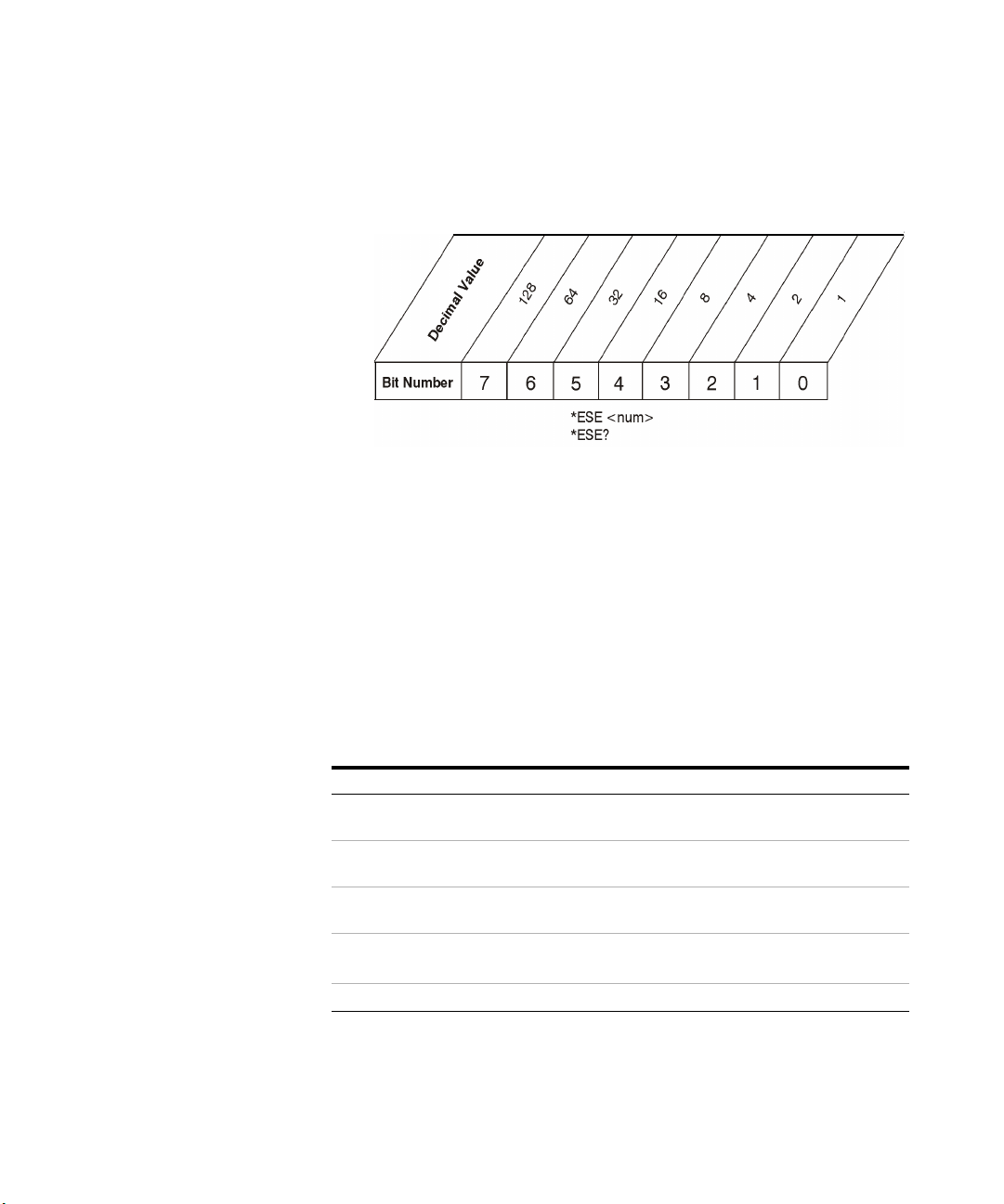
Each bit in a register is represented by a numerical value based on
its location. See figure below. This number is sent with the
command to enable a particular bit. If you want to enable more
than one bit, you would send the sum of all the bits that you want
to monitor.
Status Registers
How to use the Status Registers
Example
1 To enable bit 0 and bit 6 of standard event status register, you
would send the command *ESE 65 because 1 + 64 = 65.
2 The results of a query are evaluated in a similar way. If the *STB?
command returns a decimal value of 140, (140 = 128 + 8 + 4) then
bit 7 is true, bit 3 is true and bit 2 is true.
27
Page 34
Status Registers
Event Enable Reg
.
7654321
0
&
&
&
&
&
&
&
+
0
1
2
3
4
5
6
7
Status Byte Register (*STB?)
Unused
Unused
Error/Event Queue Summary
Questionable Status Summary
Message Available (MAV)
Std. Event Status Sum
Req. Serv. Sum (RQS)
Operation Status Sum
+
0
1
2
3
4
5
6
7
Standard Event Status Register
Oper. Complete
Req. Bus Control
Query Error
Dev. Dep. Error
Execution Error
Command Error
Reserved
Power on
Service Request Enable Register
(*ESE,*ESE?,*ESR?,*OPC)
(*SRE,*SRE?)
Standard OPERation
&
+
0
1
2
3
4
5
6
7
8
9
10
11
12
13
14
15
STATus:QUEStionable:INTegrity
Reserved
Reserved
Reserved
Reserved
Reserved
Reserved
Setting Limited/Readjusted
Always Zero
Reserved
Reserved
Reserved
Reserved
Reserved
Reserved
Reserved
Reserved
+
0
1
2
3
4
5
6
7
8
9
10
11
12
13
14
15
Reserved
Reserved
Reserved
Reserved
Reserved
Reserved
Reserved
Always Zero
Reserved
Reserved
Reserved
Reserved
MEASuring
Reserved
Reserved
Reserved
Status Register System
Status Register System
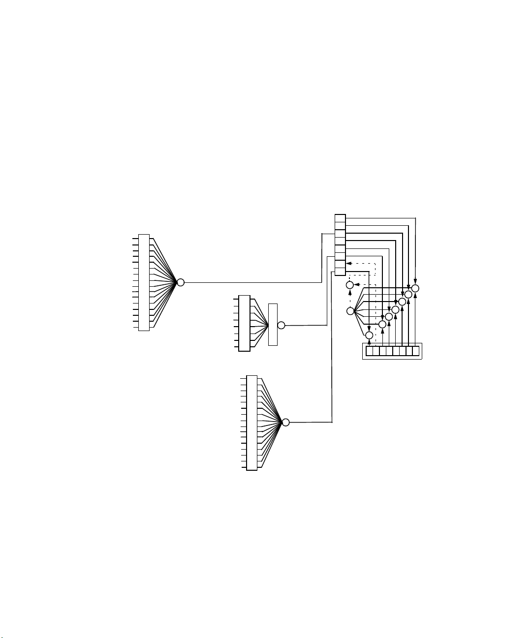
The hardware status registers are combined to form the instrument
status system. Specific status bits are assigned to monitor various
aspects of the instrument operation and status. See the following
diagram of the status system for information about the bit
assignments and status register interconnections.
Figure 1 Keysight N9320B Status Register System
28
Page 35

Status Register System
Setting and Querying the Status Register
Each bit in a register is represented by a numerical value based on
its location. This number is sent with the command to enable a
particular bit. To enable more than one bit, send the sum of all of
the bits involved.
For example, to enable bit 0 and bit 6 of the standard event status
register, you would send the command *ESE 65 (1 + 64).
The results of a query are evaluated in a similar way. If the *STB?
command returns a decimal value of 140, (140 = 128 + 8 + 4) then
bit 7 is true, bit 3 is true, and bit 2 is true.
Status Registers
29
Page 36
Status Registers
0
1
2
3
4
5
6
7
Status Byte Register
Unused
Unused
Error/Event Queue Summary Bit
Unused
Message Available (MAV)
Standard Event Summary Bit
Unused
Operation Status Summary Bit
&
&
&
&
&
&
&
+
0 1 2 3 4 5 6 7
Service Request
Enable Register
Status Register System
The Status Byte Register
30
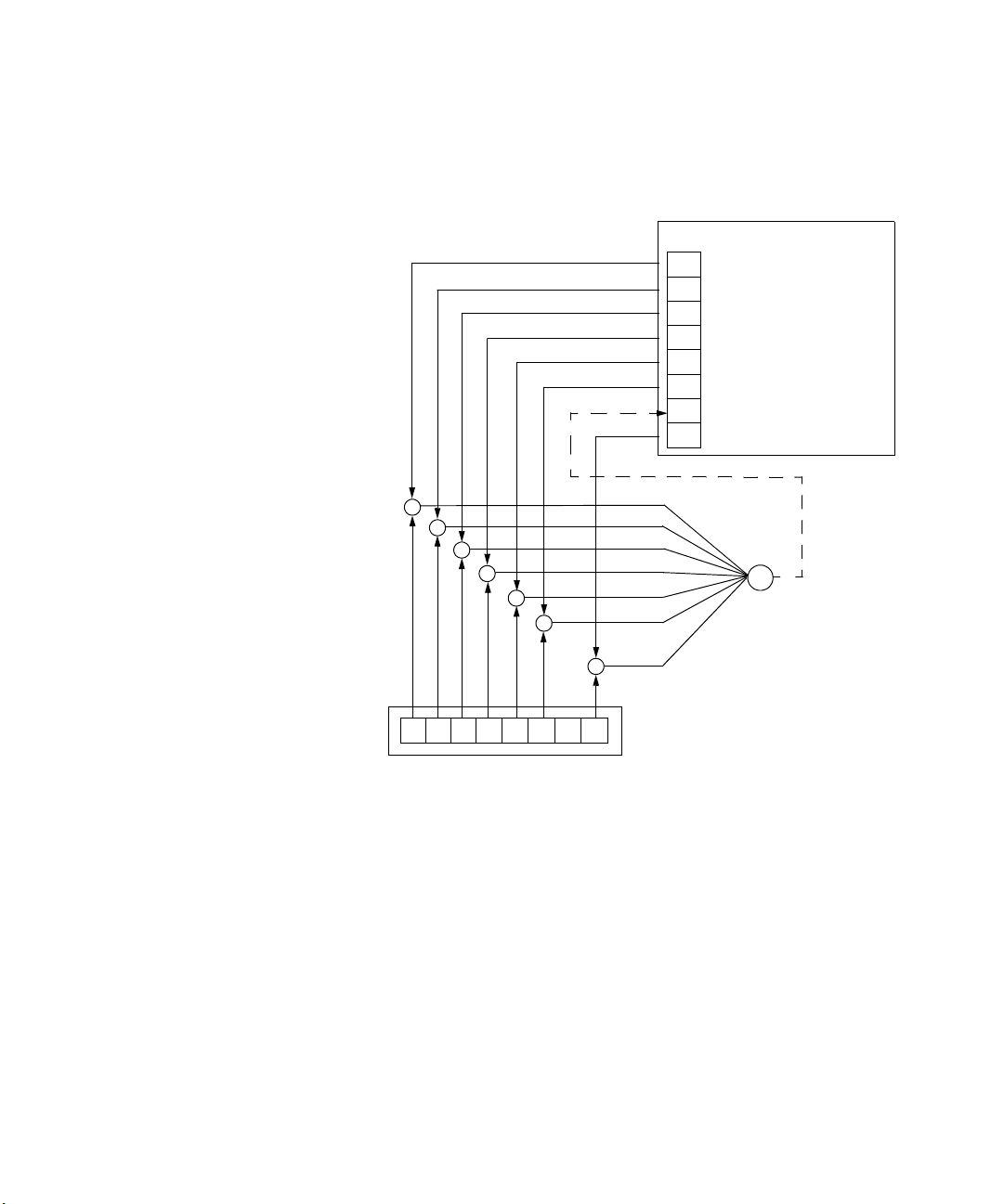
The RQS bit is read and reset by a serial poll. The same bit position
(MSS) is read, non-destructively by the *STB? command. If you
serial poll bit 6 it is read as RQS, but if you send *STB it reads bit 6
as MSS. For more information refer to IEEE 488.2 standards,
section 11.
Page 37

Status Registers
Status Register System
The status byte register contains the following bits:
Bit Description
0,1 Unused: These bits are always set to 0.
2 Error/Event Queue Summary Bit: A 1 in this bit position indicates that the SCPI error queue is not empty. The
SCPI error queue contains at least one error message.
3 Questionable Status Summary Bit: A 1 in this bit position indicates that the questionable status summary bit
has been set. The questionable status event register can then be read to determine the specific condition that
caused this bit to be set.
4 Message Available (MAV): A 1 in this bit position indicates that the analyzer has data ready in the output queue.
There are no lower status groups that provide input to this bit.
5 Standard Event Status Summary Bit: A 1 in this bit position indicates that the standard event status summary
bit has been set. The standard event status register can then be read to determine the specific event that
caused this bit to be set.
6
Request Service (RQS) Summery Bit: A 1 in this bit position indicates that the analyzer has at least one reason
to report a status change. This bit is also called the master summary status bit (MSS).
7
Operation Status Summary Bit: A 1 in this bit position indicates that the operation status summary bit has been
set. The operation status event register can then be read to determine the specific event that caused this bit to
be set.
To query the status byte register, send the *STB command. The
response will be the decimal sum of the bits that are set to 1. For
example, if bit number 7 and bit number 3 are set to 1, the decimal
sum of the 2 bits is 128 plus 8. So the decimal value 136 is
returned.
In addition to the status byte register, the status byte group also
contains the service request enable register. The status byte
service request enable register lets you choose which bits in the
Status Byte Register will trigger a service request.
31
Page 38
Status Registers
Operation Complete
Request Bus Control
Query Error
Device Dependent Error
Execution Error
Command Error
User Request
Power On
&
&
&
&
&
&
&
+
0 1 2 3 4 5 6 7
Event Enable Register
&
0
1 2
3 4 5 6 7
To Status Byte Register bit #5
Standard Event Status Register
Status Register System
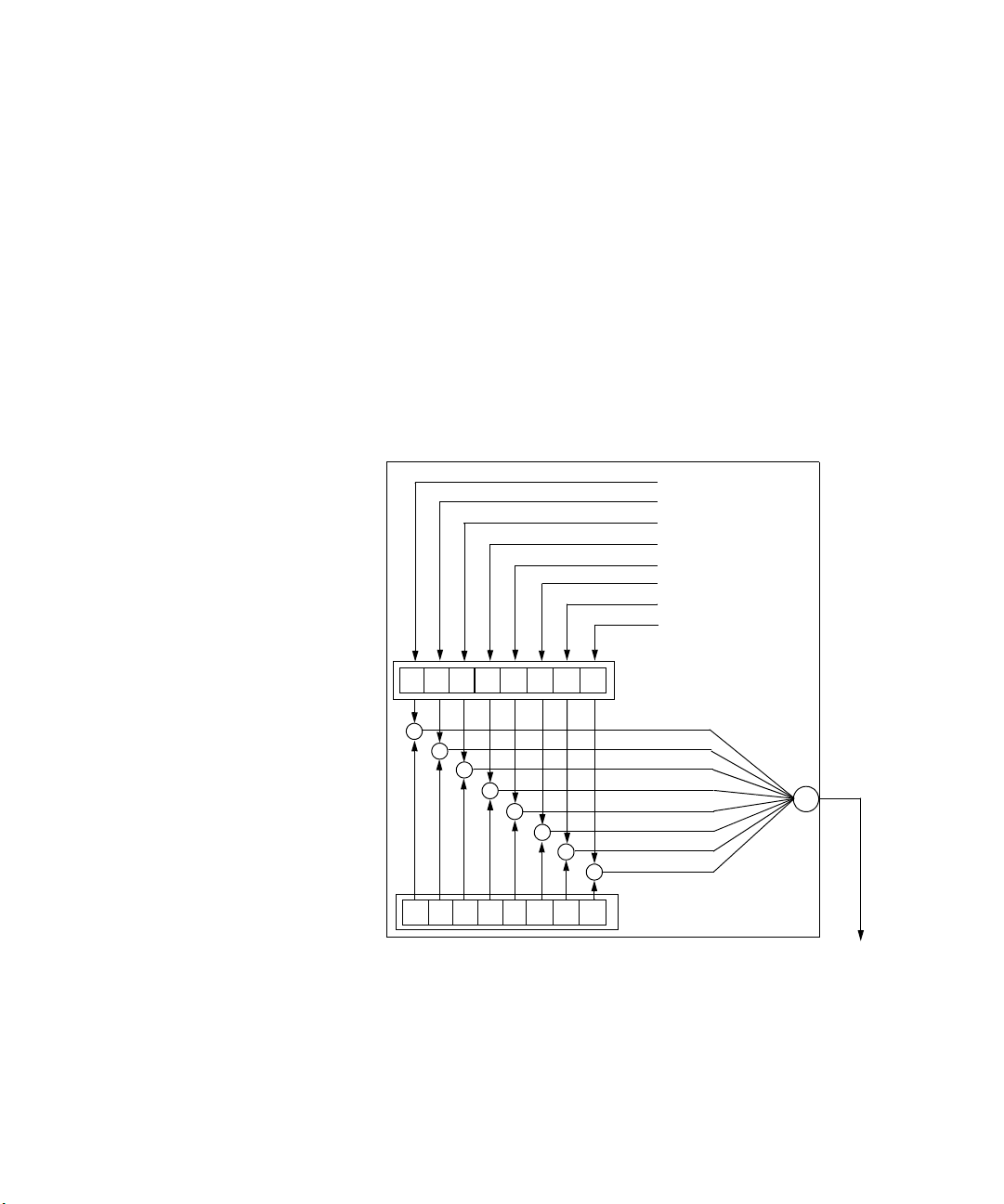
Standard Event Status Register
The standard event status register is used to determine the specific
event that sets bit 5 in the status byte register. The standard event
status register does not have negative and positive transition
registers, nor a condition register. Use the IEEE common
commands to access the register.
To query the standard event status register, send the *ESR
command. The response will be the decimal sum of the bits which
are set to 1. For example, if bit number 7 and bit number 3 are set
to 1, the decimal sum of the 2 bits is 128 plus 8. So the decimal
value 136 is returned.
Figure 2 Standard Event Status Register Diagram
32
Page 39

Status Registers
Status Register System
The standard event status register contains following bits:
Bit Description
0 Unused
1 Request Bus Control: This bit is always set to 0. (The analyzer does not request control.)
2
Query Error: A 1 in this bit position indicates that a query error has occurred. Query errors have SCPI error
numbers from 499 to 400.
3
Device Dependent Error: A 1 in this bit position indicates that a device dependent error has occurred. Device
dependent errors have SCPI error numbers from –399 to –300 and 1 to 32767.
4 Execution Error: A 1 in this bit position indicates that an execution error has occurred. Execution errors have
SCPI error numbers from –299 to –200.
5
Command Error: A 1 in this bit position indicates that a command error has occurred. Command errors have
SCPI error numbers from –199 to –100.
6
User Request Key (Local): A 1 in this bit position indicates that the [Preset/System] (Local) key has been
pressed. This is true even if the analyzer is in local lockout mode.
7
Power On: A 1 in this bit position indicates that the analyzer has been turned off and then on.
The standard event status register is used to determine the specific
event that set bit 5 in the status byte register. To query the
standard event status register, send the command *ESR?. The
response will be the decimal sum of the bits which are enabled (set
to 1). For example, if bit number 7 and bit number 3 are enabled,
the decimal sum of the 2 bits is 128 plus 8. So the decimal value
136 is returned.
In addition to the standard event status register, the standard
event status group also contains a standard event status enable
register. This register lets you choose which bits in the standard
event status register will set the summary bit (bit 5 of the status
byte register) to 1. Send the *ESE <integer> command where
<integer> is the sum of the decimal values of the bits you want to
enable. For example, to enable bit 7 and bit 6 so that whenever
either of those bits is set to 1, the standard event status summary
bit of the status byte register will be set to 1, send the command
*ESE 192 (128 + 64). The command *ESE? returns the decimal
value of the sum of the bits previously enabled with the *ESE
<integer> command.
33
Page 40
Status Registers
Status Register System
STATus:OPERation Ragister
The standard event status enable register presets to zeros (0).
Figure 3 Standard Event Status Event Enable Register
The STATus:OPERation register is used to determine the specific
event that sets bit 7 in the status byte register. This register also
monitors the current measurement state and checks to see if the
analyzer is performing measuring function:
34
The STATus:OPERation condition register contains the following
bits:
Bit Description
0Reserved:
Keysight products.
1Reserved: This bit is not used by the analyzer, but is for future use with other
Keysight products.
2Reserved: This bit is not used by the analyzer, but is for future use with other
Keysight products.
3
Reserved: This bit is not used by the analyzer, but is for future use with other
Keysight products.
4
Measuring: A 1 in this bit position indicates that a measurement is in progress.
This bit is not used by the analyzer, but is for future use with other
Page 41

Status Registers
Status Register System
Bit Description
5
Reserved: This bit is not used by the analyzer, but is for future use with other
Keysight products.
6
Reserved: This bit is not used by the analyzer, but is for future use with other
Keysight products.
7
Reserved: This bit is not used by the analyzer, but is for future use with other
Keysight products.
8
Reserved: This bit is not used by the analyzer, but is for future use with other
Keysight products.
9
Reserved: This bit is not used by the analyzer, but is for future use with other
Keysight products.
10
Reserved: This bit is not used by the analyzer, but is for future use with other
Keysight products.
11
Reserved: This bit is not used by the analyzer, but is for future use with other
Keysight products.
12
Reserved: This bit is not used by the analyzer, but is for future use with other
Keysight products.
13
Reserved: This bit is not used by the analyzer, but is for future use with other
Keysight products.
14
Reserved: This bit is not used by the analyzer, but is for future use with other
Keysight products.
15
Always Zero (0)
35
Page 42

Status Registers
Status Register System
STATus:OPERation Condition and Event Enable Registers
The STATus:OPERation condition register continuously monitors
the hardware and firmware status of the analyzer, and is read-only.
To query the register, send:STATus:OPERation:CONDition?
command. The response will be the decimal sum of the bits that
are set to 1. For example, if bit number 9 and bit number 3 are set
to 1, the decimal sum of the 2 bits is 512 plus 8. So the decimal
value 520 is returned.
The STATus:OPERation event register latches transition events from
the condition register as specified by the transition filters. Event
registers are destructive read-only data. Reading data from an
event register will clear the content of that register. To query the
event register, send :STATus:OPERation:[:EVENt]?
command.
The STATus:OPERation event enable register lets you choose the
bits that will set the operation status summary bit (bit 7) of the
status byte register to 1. Send:STATus:OPERation:ENABle
<num> command where <num> is the sum of the decimal values
of the bits you want to enable.
36
For example, to enable bit 9 and bit 3 (so that whenever either bit 9
or 3 is set to 1, the operation status summary bit of the status byte
register will be set to 1), send:STATus:OPERation:ENABle
520 (512 + 8) command. The command
:STATus:OPERation:ENABle? returns the decimal value of
the sum of the bits previously enabled with
:STATus:OPERation:ENABle <num> command.
Page 43

Status Register System
STATus:QUEStionable:INTegrity Registers
STATus:QUEStionable:INTegrity register monitors the overall
analyzer condition. They are accessed with:STATus:OPERation
and :STATus:QUEStionable:INTegrity commands in the
:STATus command subsystem.
The STATus:QUEStionable:INTegrity register also monitors the
analyzer to see if there are any questionable events that occurred.
These registers look for anything that may cause an error or that
may induce a faulty measurement.
Status Registers
37
Page 44

Status Registers
Status Register System
38
Page 45

Programming Example
4 Programming Example
This chapter provides some programming conventions and examples for your
further reference.
39
Page 46

Programming Example
NOTE
Overview
Overview
The programming examples in this section keep to the following 3
conventions:
• The programming examples were written for use on an
compatible PC.
• The programming examples use USB interface.
• The programming examples are written in C programming
language and SCPI programming commands, using
Keysight VISA transition library (Keysight VTL).
The Keysight VTL is installed when you installed the Keysight IO
libraries suite.
The Keysight IO libraries suite contains the latest Keysight VTL and
is available at:
http://www.keysight.com/find/iolib
Keysight Technologies provides programming examples for illustration only. All
sample programs assume that you are familiar with the programming language
being demonstrated and the tools used to create and debug procedures.
You have a royalty-free right to use, modify, reproduce and distribute the sample
application files in any way you find useful, provided that you agree that Keysight
has no warranty, obligations, or liability for any sample application files.
40
Page 47

Programming Example
Programming in C using the VTL
Programming in C using the VTL
This section includes some basic information about programming
in the C language using Keysight VISA transition library (VTL). Note
that some of this information may not be relevant to your particular
application. For example, if you are not using VXI instruments, the
VXI references will not be relevant.
Typical Example Program Contents
The following table summaries the VTL function calls used in the
example programs.
visa.h This file is included at the beginning of the each file to provide the function prototypes and
constants defined by VTL. For C and C++ programs, you must include the visa.h header file at the
beginning of every file that contains VISA function calls:
#include “visa.h”
ViSession The ViSession is a VTL data type. Each object that will establish a communication channel must
be defined as ViSession. Sessions must firstly be opened on the default resource manager, and
then for each resource you will be using.
viOpenDefaultRM You must first open a session with the default resource manager with the viOpenDefaultRM
function, and then for each resource you will be using. This function will initialize the default
resource manager and return a pointer to that resource manager session.
viOpenDefaultRM(&sesn)
viOpen This function establishes a communication channel with the device specified. A session identifier
that can be used with other VTL functions is returned. This call must be made for each device you
will be using.
viOpenDefaultRM(&sesn)
viOpen(sesn, rsrcName, accessMode, timeout, &vi)
viPrintf
viScanf
viWrite This function synchronously sends the data pointed to by buf to the device specified by vi. Only
These are the VTL formatted I/O functions that are patterned after those used in the C
programming language. The viPrintf call sends the SCPI commands to the analyzer. The viPrintf
call can also be used to query the analyzer. The viScanf call is then used to read the results.
one synchronous write operation van occur at any one time.
viWrite(vi, buf, count, &retCount)
41
Page 48

Programming Example
Programming in C using the VTL
viRead This function synchronously reads raw data from the session specified by the vi parameter and
stores the result in location where buf is pointing. Only one synchronous read operation can occur
at any one time.
viRead(vi, buf, count, &retCount)
viClose This function must be used to close each session. When you close a device session, all data
structures that had been allocated for the session will be set free. If you close the default
resource manager session, all sessions opened using that resource manager session will be
closed.
viClose(vi);
viClose(defaultRM)
Example Program
This example program queries a USB device for an identification
string and prints the results. Note that you must change the
address if something other than the default USB address value is
required.
/*idn.c - program filename */
#include "visa.h"
#include <stdio.h>
void main ()
{
/*Open session to USB device */
viOpenDefaultRM(&defaultRM);
viStatus=viOpen(defaultRM,"USB0::2391::8472::000
0000000::0::INSTR",VI_NULL,VI_NULL,&viN9320B);
/*Initialize device */
viPrintf(viN9320B,"*RST\n");
/*Send an *IDN? string to the device */
printf(viN9320B, "*IDN?\n");
/*Read results */
viScanf(viN9320B, "%t", &buf);
/*Print results */
42
Page 49

Programming in C using the VTL
printf("Instrument identification string: %s\n",
buf);
/* Close the sessions */
viClose(viN9320B);
viClose(defaultRM);
}
Including the VISA Declarations File
For C and C++ programs, you must include the visa.h header file at
the beginning of every file that contains VTL function calls:
#include “visa.h”
This header file contains the VISA function prototypes and the
definitions for all VISA constants and error codes. The visa.h
header file includes the visatype.h header file.
The visatype.h header file defines most of the VISA types. The VISA
types are used throughout VTL to specify data types used in the
functions. For example, the viOpenDefaultRM function requires a
pointer to a parameter of type ViSession. If you find ViSession in
the visatype.h header file, you will find that ViSession is eventually
typed as an unsigned long.
Programming Example
43
Page 50

Programming Example
NOTE
Programming in C using the VTL
Opening a Session
All devices that you will be using need to be connected and in working condition
prior to the first VTL function call (viOpenDefaultRM). The system is
configured only on the first viOpenDefaultRM per process. Therefore, if
viOpenDefaultRM is called without devices connected and then called
again when devices are connected, the devices will not be recognized. You must
close ALL resource manager sessions and re-open with all devices connected
and in working condition.
A session is a channel of communication. Sessions must first be
opened on the default resource manager, and then for each device
you will be using. The following is a summary of sessions that can
be opened:
• A resource manager session is used to initialize the VISA system.
It is a parent session that knows about all the opened sessions.
A resource manager session must be opened before any other
session can be opened.
• A device session is used to communicate with a device on an
interface. A device session must be opened for each device you
will be using. When you use a device session you can
communicate without worrying about the type of interface to
which it is connected. This insulation makes applications more
robust and portable across interfaces. Typically a device is an
instrument, or a computer.
Device Sessions
There are two parts to opening a communications session with a
specific device. First you must open a session to the default
resource manager with the viOpenDefaultRM function. The first call
to this function initializes the default resource manager and returns
a session to that resource manager session. You only need to open
the default manager session once. However, subsequent calls to
viOpenDefaultRM returns a session to a unique session to the same
default resource manager resource.
44
Page 51

Programming Example
Programming in C using the VTL
Next, you open a session with a specific device with the viOpen
function. This function uses the session returned from
viOpenDefaultRM and returns its own session to identify the device
session. The following shows the function syntax:
viOpenDefaultRM (sesn);
viOpen (sesn, rsrcName, accessMode, timeout, vi);
The session returned from viOpenDefaultRM must be used in the
sesn parameter of the viOpen function. The viOpen function then
uses that session and the device address specified in the (resource
name) parameter to open a device session. The vi parameter in
viOpen returns a session identifier that can be used with other VTL
functions.
Your program may have several sessions open at the same time by
creating multiple session identifiers by calling the viOpen function
multiple times.
The following summarizes the parameters in the previous function
calls:
sesn
rsrcName
accessMode
timeout
vi
This is a session returned from the viOpenDefaultRM function that identifies the
resource manager session.
This is a unique symbolic name of the device (device address).
This parameter is not used for VTL. Use VI_NULL.
This parameter is not used for VTL. Use VI_NULL.
This is a pointer to the session identifier for this particular device session. This pointer
will be used to identify this device session when using other VTL functions.
45
Page 52

Programming Example
Programming in C using the VTL
Addressing a Session
As seen in the previous section, the rsrcName parameter in the
viOpen function is used to identify a specific device. This parameter
is made up of the VTL interface name and the device address. The
interface name is determined when you run the VTL Configuration
Utility. This name is usually the interface type followed by a
number. The following table illustrates the format of the rsrcName
for the different interface types:
The following describes the parameters used above:
board
VXI logical address
primary address
secondary address
INSTR
This optional parameter is used if you have more than one interface of the same type.
The default value for board is 0.
This is the logical address of the VXI instrument.
This is the primary address of the USB device.
This optional parameter is the secondary address of the USB device. If no secondary
address is specified, none is assumed.
This is an optional parameter that indicates that you are communicating with a
resource that is of type INSTR, meaning instrument.
Closing a Session
The viClose function must be used to close each session. You can
close the specific device session, which will free all data structures
that had been allocated for the session. If you close the default
resource manager session, all sessions opened using that resource
manager will be closed.
Since system resources are also used when searching for resources
(viFindRsrc) or waiting for events (viWaitOnEvent), the viClose
function needs to be called to free up find lists and event contexts.
46
Page 53

Checking USB Connection
Usually, using “*IDN?” verifies the data transferring between the
controller PC and the instrument.
****************************************************
#include "visa.h"
#include <stdio.h>
#define BufferSize 128
static ViStatus status;
static ViSession defaultRM;
static ViSession inst_N9320B;
static ViUInt32 rcount;
static unsigned char buffer[BufferSize];
int main(void)
{
/* Connect N9320B and read its "IDN". */
status = viOpenDefaultRM (&defaultRM);
status = viOpen (defaultRM,
"USB0::2391::8472::0000000000::0::INSTR", VI_NULL,
VI_NULL, &inst_N9320B);
if (status != VI_SUCCESS)
return -1; //failed to connect N9320B/
/* Read "IDN" from N9320B" */
status = viWrite (inst_N9320B, "*RST\n",
StringLength("*RST\n"), &rcount);
status = viWrite (inst_N9320B, "*IDN?\n",
StringLength("*IDN?\n"), &rcount);
status = viRead (inst_N9320B, buffer, BufferSize,
&rcount);
/* Close connection to N9320B. */
status = viClose (inst_N9320B);
status = viClose (defaultRM); return 1;
}
Programming Example
Checking USB Connection
47
Page 54

Programming Example
Using C with Marker Peak Search and Peak Excursion
Using C with Marker Peak Search and Peak Excursion
/************************************************************/
/* Using Marker Peak Search and Peak Excursion */
/* */
/* This example is for the N9320B Spectrum Analyzer. */
/* */
/* This C programming example does the following. */
/* The SCPI instrument commands used are given as reference. */
/* */
/* - Opens a USB session */
/* - Clears the Analyzer */
/* *CLS */
/* - Resets the Analyzer */
/* *RST */
/* - Sets the analyzer center frequency, span and units */
/* SENS:FREQ:CENT freq */
/* SENS:FREQ:SPAN freq */
/* UNIT:POW DBM */
/* - Set the input port to the 50 MHz amplitude reference */
/* CAL:SOUR:STAT ON */
/* - Set the analyzer to single sweep mode */
/* INIT:CONT 0 */
/* - Prompt the user for peak excursion and set them */
/* CALC:MARK:PEAK:EXC dB */
/* - Set the peak threshold to -90 dBm */
/* CALC:MARK:PEAK:THR:STAT ON */
/* CALC:MARK:PEAK:THR <ampl> */
/* - Trigger a sweep and delay for sweep to complete */
/* INIT:IMM */
/* - Set the marker to the maximum peak */
/* CALC:MARK:MAX */
/* - Query and read the marker frequency and amplitude */
/* CALC:MARK:X? */
/* CALC:MARK:Y? */
/* - Close the session */
/************************************************************/
48
Page 55

Programming Example
Using C with Marker Peak Search and Peak Excursion
#include <stdio.h>
#include <stdlib.h>
#include <math.h>
#include <ctype.h>
#include <string.h>
#include "visa.h"
ViSession defaultRM, viN9320B;
ViStatus errStatus;
ViChar cIdBuff[256]= {0};
char cEnter = 0;
int iResult = 0;
/*Set the input port to 50MHz amplitude reference*/
void Route50MHzSignal()
{
viQueryf(viN9320B, "*IDN?\n", "%t", &cIdBuff);
/* prompt the user*/
/* to connect the amplitude reference output to the input*/
printf ("Connect CAL OUT to the RF IN \n");
printf ("......Press Return to continue \n");
scanf( "%c",&cEnter);
/*Externally route the 50MHz Signal*/
viPrintf(viN9320B,"CAL:SOUR:STAT ON \n");
}
void main()
{
/*Program Variables*/
ViStatus viStatus = 0;
double dMarkerFreq = 0;
double dMarkerAmpl = 0;
float fPeakExcursion =0;
49
Page 56

Programming Example
Using C with Marker Peak Search and Peak Excursion
/*Open a USB session.*/
viStatus=viOpenDefaultRM(&defaultRM);
viStatus=viOpen(defaultRM,"USB0::2391::8472::0000000000::0::INSTR",V
I_NULL,VI_NULL,&viN9320B);
if(viStatus)
{
printf("Could not open a session to USB device\n");
exit(0);
}
/*Clear the instrument*/
viClear(viN9320B);
/*Reset the instrument*/
viPrintf(viN9320B,"*RST\n");
/*Set Y-Axis units to dBm*/
viPrintf(viN9320B,"UNIT:POW DBM\n");
/*Set the analyzer center frequency to 50MHZ*/
viPrintf(viN9320B,"SENS:FREQ:CENT 50e6\n");
50
/*Set the analyzer span to 50MHZ*/
viPrintf(viN9320B,"SENS:FREQ:SPAN 50e6\n");
/*Display the program heading */
printf("\n\t\t Marker Program \n\n" );
/* Check for the instrument model number and route the 50MHz signal
accordingly*/
Route50MHzSignal();
/*Set analyzer to single sweep mode*/
viPrintf(viN9320B,"INIT:CONT 0 \n ");
/*User enters the peak excursion value*/
printf("\t Enter PEAK EXCURSION in dB: ");
scanf( "%f",&fPeakExcursion);
Page 57

Programming Example
Using C with Marker Peak Search and Peak Excursion
/*Set the peak excursion*/
viPrintf(viN9320B,"CALC:MARK:PEAK:EXC %1fDB \n",fPeakExcursion);
/*Set the peak thresold */
viPrintf(viN9320B,"CALC:MARK:PEAK:THR -90 \n");
/*Trigger a sweep and wait for completion*/
viPrintf(viN9320B,"INIT:IMM \n");
/*Set the marker to the maximum peak*/
viPrintf(viN9320B,"CALC:MARK:MAX \n");
/*Query and read the marker frequency*/
viQueryf(viN9320B,"CALC:MARK:X? \n","%lf",&dMarkerFreq);
printf("\n\t RESULT: Marker Frequency is: %lf MHZ \n\
n",dMarkerFreq/10e5);
/*Query and read the marker amplitude*/
viQueryf(viN9320B,"CALC:MARK:Y?\n","%lf",&dMarkerAmpl);
printf("\t RESULT: Marker Amplitude is: %lf dBm \n\n",dMarkerAmpl);
/*Close the session*/
viClose(viN9320B);
viClose(defaultRM);
}
51
Page 58

Programming Example
Using Marker Delta Mode and Marker Minimum Search
Using Marker Delta Mode and Marker Minimum Search
/************************************************************/
/* Using Marker Delta Mode and Marker Minimum Search */
/* */
/* This example is for the N9320B Spectrum Analyzers */
/* */
/* This C programming example does the following. */
/* The SCPI instrument commands used are given as reference. */
/* */
/* - Opens a USB session */
/* - Clears the Analyzer */
/* - Resets the Analyzer */
/* *RST */
/* - Set the input port to the 50 MHz amplitude reference */
/* CAL:SOUR:STAT ON */
/* - Set the analyzer to single sweep mode */
/* INIT:CONT 0 */
/* - Prompts the user for the start and stop frequencies */
/* - Sets the start and stop frequencies */
/* SENS:FREQ:START freq */
/* SENS:FREQ:STOP freq */
/* - Trigger a sweep and delay for sweep completion */
/* INIT:IMM */
/* - Set the marker to the maximum peak */
/* CALC:MARK:MAX */
/* - Set the analyzer to activate the delta marker */
/* CALC:MARK:MODE DELT */
/* - Trigger a sweep and delay for sweep completion */
/* INIT:IMM */
/* - Set the marker to the minimum amplitude mode */
/* CALC:MARK:MIN */
/* - Query and read the marker amplitude */
/* CALC:MARK:Y? */
/* - Close the session */
/************************************************************/
52
Page 59

Programming Example
Using Marker Delta Mode and Marker Minimum Search
#include <stdio.h>
#include <stdlib.h>
#include <math.h>
#include <ctype.h>
#include <string.h>
#include "visa.h"
ViSession defaultRM, viN9320B;
ViStatus errStatus;
ViChar cIdBuff[256] ={0};
char cEnter = 0;
int iResult =0;
/*Set the input port to the 50MHz amplitude reference*/
void Route50MHzSignal()
{
viQueryf(viN9320B, "*IDN?\n", "%t", &cIdBuff);
/* prompt the user*/
/* to connect the amplitude reference output to the
input*/
printf ("Connect CAL OUT to the RF IN \n");
printf ("......Press Return to continue \n");
scanf( "%c",&cEnter);
/*Externally route the 50MHz Signal*/
viPrintf(viN9320B,"CAL:SOUR:STAT ON \n");
}
void main()
{
/*Program Variable*/
ViStatus viStatus = 0;
double dStartFreq =0.0;
double dStopFreq =0.0;
double dMarkerAmplitude = 0.0;
{
53
Page 60

Programming Example
Using Marker Delta Mode and Marker Minimum Search
/* Open an USB session*/
viStatus=viOpenDefaultRM(&defaultRM);
viStatus=viOpen(defaultRM,"USB0::2391::8472::9876543210::0::INSTR",VI
_NULL,VI_NULL,&viN9320B);
if(viStatus)
printf("Could not open a session to USB device!\n");
exit(0);
}
/*Clear the instrument*/
viClear(viN9320B);
/*Reset the instrument*/
viPrintf(viN9320B,"*RST\n");
/*Display the program heading */
printf("\n\t\t Marker Delta Program \n\n" );
/*Check for the instrument model number and route the 50MHz
signal accordingly*/
Route50MHzSignal();
54
/*Set the analyzer to single sweep mode*/
viPrintf(viN9320B,"INIT:CONT 0\n");
/*Prompt the user for the start frequency*/
printf("\t Enter the Start frequency in MHz ");
/*The user enters the start frequency*/
scanf("%lf",&dStartFreq);
/*Prompt the user for the stop frequency*/
printf("\t Enter the Stop frequency in MHz ");
/*The user enters the stop frequency*/
scanf("%lf",&dStopFreq);
Page 61

Programming Example
Using Marker Delta Mode and Marker Minimum Search
/*Set the analyzer to the values given by the user*/
//viPrintf(viN9320B,"SENS:FREQ:STAR %lf
//MHZ;:SENS:FREQ:STOP %lf MHZ\n",dStartFreq,dStopFreq);
viPrintf(viN9320B,":SENS:FREQ:STAR %lf MHz\n",dStart-
Freq);
viPrintf(viN9320B,":SENS:FREQ:STOP %lf MHZ\n",dStopFreq);
/*Trigger a sweep, delay for completion*/
viPrintf(viN9320B,"INIT:IMM\n");
//delay(1);
/*Set the marker to the maximum peak*/
viPrintf(viN9320B,"CALC:MARK:MAX\n");
/*Set the analyzer to activate delta marker mode*/
viPrintf(viN9320B,"CALC:MARK:MODE DELT\n");
/*Trigger a sweep, delay for completion*
viPrintf(viN9320B,"INIT:IMM\n");
Sleep(1);
/*Set the marker to minimum amplitude*/
viPrintf(viN9320B,"CALC:MARK:MIN\n");
/*Query and read the marker amplitude*/
viQueryf(viN9320B,"CALC:MARK:Y?\n","%lf",&dMarkerAmpli-
tude);
/*print the marker amplitude*/
printf("\n\n\tRESULT: Marker Amplitude Delta =%lf dB\n\
n",dMarkerAmplitude);
/*Close the session*/
viClose(viN9320B);
viClose(defaultRM);
}
55
Page 62

Programming Example
Measuring Phase Noise
Measuring Phase Noise
/************************************************************/
/* Measuring Phase Noise */
/* */
/* This example is for the N9320B Spectrum Analyzers */
/* */
/* This C programming example does the following. */
/* The SCPI instrument commands used are given as reference. */
/* */
/* - Opens a USB session */
/* - Clears the Analyzer */
/* - Resets the Analyzer */
/* *RST */
/* - Sets the center frequency and span */
/* SENS:FREQ:CENT 50 MHZ */
/* SENS:FREQ:SPAN 10 MHZ */
/* - Set the input port to the 50 MHz amplitude reference */
/* CAL:SOUR:STAT ON */
/* - Set the marker to the maximum peak */
/* CALC:MARK1:MAX */
/* - Activate the phase noise function */
/* CALC:MARK1:PHN ON*/
/* - Set offset to 20 kHz */
/* CALC:PHN:OFFS 20KHz */
/* - Query the phase noise */
/* CALC:MARK:PHN:Y? */
/* - Close the session */
/************************************************************/
56
#include <stdio.h>
#include <stdlib.h>
#include <math.h>
#include <ctype.h>
#include <string.h>
#include "visa.h"
Page 63

Programming Example
Measuring Phase Noise
ViSession defaultRM, viN9320B;
ViStatus errStatus;
ViChar cIdBuff[256]= {0};
char cEnter = 0;
int iResult = 0;
/*Set the input port to 50 MHz amplitude reference*/
void Route50MHzSignal()
{
viQueryf(viN9320B, "*IDN?\n", "%t", &cIdBuff);
/* prompt the user*/
/* to connect the amplitude reference output to the input*/
printf ("Connect CAL OUT to the RF IN \n");
printf ("......Press Return to continue \n");
scanf( "%c",&cEnter);
/*Externally route the 50 MHz Signal*/
viPrintf(viN9320B,"CAL:SOUR:STAT ON \n");
}
void main()
{
/*Program Variables*/
ViStatus viStatus = 0;
double dMarkAmp =0.0;
/*Open a USB session*/
viStatus=viOpenDefaultRM(&defaultRM);
viStatus=viOpen(defaultRM,"USB0::2391::8472::0000000000::0::INSTR",VI_NU
LL,VI_NULL,&viN9320B);
if(viStatus)
{
printf("Could not open a session to USB device!\n");
exit(0);
}
/*Clear the Instrument*/
viClear(viN9320B);
57
Page 64

Programming Example
Measuring Phase Noise
/*Reset the Instrument*/
/*Display the program heading */
signal accordingly*/
/*Activate the noise marker function.*/
nal.*/
viPrintf(viN9320B,"*RST\n");
printf("\n\t\t Noise Program \n\n" );
/* Check for the instrument model number and route the 50 MHz
Route50MHzSignal();
/*Set the analyzer center frequency to 50 MHz*/
viPrintf(viN9320B,"SENS:FREQ:CENT 50e6\n");
/*Set the analyzer span to 10 MHz*/
viPrintf(viN9320B,"SENS:FREQ:SPAN 10e6\n");
/*Set the marker to the maximum peak*/
viPrintf(viN9320B,"CALC:MARK1:MAX \n");
viPrintf(viN9320B,"CALC:MARK1:PHN ON \n");
/*Set the offset to 20 kHz. This places the
active marker two divisions to the right of the input sig-
viPrintf(viN9320B,":CALC:PHN:OFFS 20KHz \n");
58
/*Query and read the phase noise from the analyzer */
viQueryf(viN9320B,":CALC:MARK:PHN:Y? \n","%lf",&dMarkAmp);
/*Report the phase nosie */
printf("\t Marker Amplitude =%lf dBc/Hz\n",dMarkAmp);
/*Close the session*/
viClose(viN9320B);
viClose(defaultRM);
}
Page 65

Command Reference
5 Command Reference
This chapter contains SCPI (Standard Commands for Programmable
Instruments) programming commands for the spectrum analyzer core
operation.
59
Page 66

Command Reference
IEEE Common Commands
IEEE Common Commands
The first few pages of this chapter contain common commands
specified in IEEE Standard 488.2-1992, IEEE Standard Codes,
Formats, Protocols and Common Commands for Use with
ANSI/IEEE Std 488.1-1987. New York, NY, 1992.
Following these commands, the Keysight N9320B spectrum
analyzers SCPI commands are listed.
Clear Status
*CLS
Clears the status byte register. It does this by emptying the error
queue and clearing all bits in all of the event registers. The status
byte register summarizes the states of the other registers.
responsible for generating service requests.
Remark: See *STB?
Standard Event Status Enable
It is also
60
*ESE <number>
*ESE?
Sets the bits in the standard event status enable register. This
register monitors I/O errors and synchronization conditions such as
operation complete, request control, query error, device dependent
error, execution error, command error and power on. A summary
bit is generated on execution of the command.
The query returns the state of the standard event status enable
register.
Range: Integer, 0 to 255
Example: *ESE 36 Enables the Standard Event Status Register to monitor
query and command errors (bits 2 and 5).
*ESE? Returns a 36 indicating that the query and command status
bits are enabled.
Page 67

Command Reference
Preset/
System
IEEE Common Commands
Standard Event Status Register Query
*ESR?
Queries and clears the standard event status event register. (This is
a destructive read.) The value returned reflects the current state
(0/1) of all the bits in the register.
Range: Integer, 0 to 255
Example: *ESR? returns a 1 if there is either a query or command error,
otherwise it returns a zero.
Identification Query
*IDN?
Returns an instrument identification information string. The string
will contain the model number, serial number and firmware
revision. The response is organized into four fields separated by
commas. The field definitions are manufacturer, model, serial
number and software version.
Example: *IDN? returns instrument information, such as:
Keysight Technologies, N9320B, 45310116, A.01.02
Key access: > More > Show system
Operation Complete Query
*OPC
*OPC?
Sets bit 0 in the standard event status register to “1” when all
pending operations have finished.
The query stops any new commands from being processed until the
current processing is complete. Then it returns a “1”, and the
program continues. This query can be used to synchronize events
of other instruments on the external bus.
Returns a “1” if the last processing is complete. Use this query
when there’s a need to monitor the command execution status,
such as a sweep execution.
61
Page 68

Command Reference
NOTE
Preset/
System
IEEE Common Commands
The preset performed by *RST is always a factory preset. That is, the same
preset performed by
to
Key access: > Preset
*OPC and *OPC? are currently effective only when immediately
preceded by either the :INITiate:IMMediate or a :CALibration
command.
Reset
*RST
This command presets the instrument to a factory defined
condition that is appropriate for remote programming operation.
*RST is equivalent to performing the two commands
:SYSTem:PRESet and *CLS. This command always performs a
factory preset.
:SYSTem:PRESet when :SYSTem:PRESet:TYPE is set
FACTory.
62
Service Request Enable
*SRE <integer>
*SRE?
This command enables the desired bits of the service request
enable register.
The query returns the value of the register, indicating which bits are
currently enabled. The default value is 255.
Example: *SRE 16
Range: Integer, 0 to 255
enables bits 4 in the service request enable register.
Page 69

Command Reference
IEEE Common Commands
Status Byte Query
*STB?
Returns the value of the status byte register without erasing its
contents.
Range: Integer, 0 to 255
Example: If a 16 is returned, it indicates that bit 5 is set and one of the
conditions monitored in the standard event status register is set.
Self Test Query
*TST?
This query is used by some instruments for a self test.
Range: Integer, 0 to 255
Wait-to-Continue
*WAI
This command causes the instrument to wait until all pending
commands are completed before executing any additional
commands. There is no query form to the command.
Range: Integer, 0 to 255
63
Page 70

Command Reference
Auto
Tun e
Peak
Search
CALCulate Subsystem
CALCulate Subsystem
This subsystem is used to perform post-acquisition data
processing. In effect, the collection of new data triggers the
CALCulate subsystem. In this instrument, the primary functions in
this subsystem are markers and limits. CALCulate subsystem
commands used for measurements in the MEAS menus are located
in "SENSe Subsystem“ on page 122.
Autotune
:CALCulate:AUTOtune
Enable the analzer’s auto tune function.
Key access:
NdBpoints
64
:CALCulate:BWIDth|BANDwidth:NDB <rel_ampl>
:CALCulate:BWIDth|BANDwidth:NDB?
Selects the power level, below the peak of the signal, at which the
signal bandwidth will be measured by the markers.
:CALCulate:BWIDth|BANDwidth[:STATe] must be ON.
*RST: –3 dB
Range: –80 dB to –1 dB
Remarks: Refer to :CALCulate:BWIDth|BANDwidth[:STATe] for an
explanation of this marker function.
Key access: > More > N dB Points
Page 71
NdBresults
Peak
Search
Peak
Search
:CALCulate:BWIDth|BANDwidth:RESult?
Returns the measured bandwidth at the power level defined by
:CALCulate:BWIDth:NDB?. 0 is returned if
:CALCulate:BWIDth|BANDwidth[:STATe] is off, or when a
result is not available. Refer to
CALCulate:BWIDth|BANDwidth[:STATe] for further explanation
of this marker function.
Default Unit: Hz
Key access: > More > N dB Points
NdBstate
:CALCulate:BWIDth|BANDwidth[:STATe] OFF|ON|0|1
:CALCulate:BWIDth|BANDwidth[:STATe]?
Controls the bandwidth measurement function. The function
measures the bandwidth, at the number of dB down specified in
:CALCulate:BWIDth:NDB, of the maximum signal on the display.
Command Reference
CALCulate Subsystem
*RST: Off
Remarks: When this command is turned on, the bandwidth measurement
function (N dB Points) is associated with the active marker. If no
marker is active at the time this command is turned on, marker 1
becomes the active marker, and a peak search is performed. No
restrictions exist for moving the bandwidth measurement function
markers to any other signal on the display. However, when this
function is turned on, all other concurrent marker functions are
suspended.
Key access: > More > N dB Points On Off
Test Current Trace Data Against all Limit Lines
:CALCulate:CLIMits:FAIL?
Queries the status of the limit line testing. Returns a 0 if the trace
data passes when compared with all the current limit lines. Returns
a 1 if the trace data fails any limit line test.
65
Page 72

Command Reference
Det/
Display
CALCulate Subsystem
CALCulate:LLINe Subsection
Limit lines can be defined for your measurement. You can then
have the instrument compare the data to your defined limits and
indicate a pass/fail condition.
Delete All Limit Lines in Memory
:CALCulate:LLINe:ALL:DELete
Deletes all limit lines in volatile memory.
Key access:
> Limits > Delete All Limits
Define Limit Line Values
:CALCulate:LLINe[1]|2:DATA<x-axis>,<ampl>,<connected>
{,<x-axis>,<ampl>,<connected>}
:CALCulate:LLINe[1]|2:DATA?
Defines limit line values, and destroys all existing data. Up to 20
points may be defined for each limit. No units are allowed.
• <x-axis> – frequency values
• <ampl> – amplitude values are in the current Y-axis units. Up to
two amplitude values can be provided for each x-axis value, by
repeating <x-axis> in the data list. No unit is allowed in this
parameter.
• <connected> – connected values are either 0 or 1. 1 means the
point should be connected to the previously point to define the
limit line. 0 means that it is a point of discontinuity and is not
connected to the preceding point.
Example: CALC:LLIN1:DATA 1000000000,–20,0,200000000,–30,1
Range: <x-axis>
<ampl>
<connected>
9 kHz to 3 GHz
–100 dBm to +30 dBm
0 or 1
66
Page 73

Command Reference
y
y
i
1+
y
i
–
f
i
1+
f
i
–
----------------------------
ff
i
–
y
i
+=
y
y
i
1+
y
i
–
f
log
i
1+
f
log
i
–
------------------------------------- -------------
f
log
f
i
log–
y
i
+=
y
log
y
log
i
1+
y
log
i
–
f
i
1+
f
i
–
----------------------------------- ---------------
ff
i
–ylog
i
+=
y
log
y
log
i
1+
y
log
i
–
f
log
i
1+
f
log
i
–
------------------------------------ --------------
f
logflog
i
–
y
log
i
+=
Det/
Display
Det/
Display
CALCulate Subsystem
Remarks: If two amplitude values are entered for the same frequency, a
single vertical line is the result. In this case, if an upper line is
chosen, the amplitude of lesser frequency (amplitude 1) is tested. If
a lower line is chosen, the amplitude of greater frequency
(amplitude 2) is tested.
For linear amplitude interpolation and linear frequency
interpolation, the interpolation is computed as:
For linear amplitude interpolation and log frequency interpolation,
the interpolation is computed as:
For log amplitude interpolation and linear frequency interpolation,
the interpolation is computed as:
Key access:
Key access:
For log amplitude interpolation and linear frequency interpolation,
the interpolation is computed as:
> Limits > Limit 1|2 > Edit
Delete Limit Line
:CALCulate:LLINe[1]|2:DELete
Deletes the selected limit line.
> Limits > Limit 1|2 > Delete Limit
67
Page 74

Command Reference
Det/
Display
Det/
Display
Det/
Display
CALCulate Subsystem
Display the Limit Line
:CALCulate:LLINe[1]|2:DISPlay OFF|ON|0|1
:CALCulate:LLINe[1]|2:DISPlay?
Controls the display of the current limit line.
*RST: Off
Key access:
> Limits > Limit 1|2 > Limit On Off
Test the Data Against the Limit Line
:CALCulate:LLINe[1]|2:FAIL?
Queries the status of the limit line testing. Returns a 0 if the data
passes, and returns a 1 if there is a failure. This query value is valid
only if margin or limit test is On. Use the command
:CALCulate:LLINe[1]|2:STATe OFF|ON|0|1 to activate limit
line testing.
Key access:
> Limits > Limit 1|2 > Test On Off
Set the Margin Size
:CALCulate:LLINe[1]|2:MARGin <rel_ampl>
:CALCulate:LLINe[1]|2:MARGin?
Defines the amount of measurement margin that is added to the
designated limit line.
*RST: Off
Remarks: The margin must be negative for upper limit lines, and positive for
lower limits.
Key access:
> Limits > Limit 1|2 > Margin On Off
68
Page 75
Display the Limit Margin
Det/
Display
Det/
Display
Det/
Display
:CALCulate:LLINe[1]|2:MARGin:STATe OFF|ON|0|1
:CALCulate:LLINe[1]|2:MARGin:STATe?
Displays a measurement margin that is added to the designated
limit line to do secondary testing of the data.
*RST: Off
Command Reference
CALCulate Subsystem
Key access:
*RST: Off
Key access:
> Limits > Limit 1|2 > Margin On Off
Control Limit Line Testing
:CALCulate:LLINe[1]|2:STATe OFF|ON|0|1
:CALCulate:LLINe[1]|2:STATe?
Turns limit line testing on/off. The limit and margin will only be
tested if they are displayed. Use
on the display of limit lines, and
:CALCulate:LLINe[1]|2:DISPlay to turn
:CALCulate:LLINe[1]|2:MARGin:STATe
to turn on the display of margins. If margin and limit display are
both turned off, limit test is automatically turned off. Use
:CALCulate:LLINe[1]|2:FAIL? to return the state of pass or fail after
limit line state has been turned on.
> Limits > Limit 1|2 > Limit On Off
Select the Type of Limit Line
:CALCulate:LLINe[1]|2:TYPE UPPer|LOWer
:CALCulate:LLINe[1]|2:TYPE?
Sets a limit line to be either an upper or lower type limit line. An
upper line will be used as the maximum allowable value when
comparing with the data.
*RST: Lower
Remarks: If a margin has already been set for this limit line, and this
command is used to change the limit type, then the margin value is
reset to 0 dB.
Key access:
> Limits > Limit 1|2 > Type Upper Lower
69
Page 76
Command Reference
Marker
NOTE
Peak
Search
Marker
CALCulate Subsystem
CALCulate:MARKer Subsection
Markers All Off on All Traces
:CALCulate:MARKer:AOFF
Turns off all markers on all the traces.
Key access:
> All Off
Continuous Peaking Marker Function
:CALCulate:MARKer[n]:CPEak[:STATe] OFF|ON|0|1
:CALCulate:MARKer[n]:CPEak[:STATe]?
Turns on or off continuous peaking. It continuously puts the
selected marker on the highest displayed signal peak.
This function is intended to maintain the marker on signals with a
frequency that is changing, and an amplitude that is not changing.
*RST: Off
Remarks: This command may not be used to activate a given marker.
Key access: > More > Continuous Pk On Off
Frequency Counter Marker Resolution
:CALCulate:MARKer:FCOunt:RESolution <real>
:CALCulate:MARKer:FCOunt:RESolution?
Sets the resolution of the marker frequency counter. Setting the
resolution to AUTO will couple the marker counter resolution to the
frequency span.
*RST: 1 kHz
70
Range: 0.1 Hz to 1 kHz
Default Unit: Hz
Key access:
> Function > Freq Counter > Resolution Auto Man
Page 77

Frequency Counter Marker Automatic Resolution
Marker
Marker
:CALCulate:MARKer:FCOunt:RESolution:AUTO OFF|ON|0|1
:CALCulate:MARKer:FCOunt:RESolution:AUTO?
Sets the resolution of the marker frequency counter so it is
automatically coupled to the frequency span, generating the
fastest accurate count.
*RST: On
Command Reference
CALCulate Subsystem
Key access:
> Function > Freq Counter > Resolution Auto Man
Frequency Counter Marker
:CALCulate:MARKer[n]:FCOunt[:STATe] OFF|ON|0|1
:CALCulate:MARKer[n]:FCOunt[:STATe]?
Turns on or off the marker frequency counter. To query the
frequency counter, use
:CALCulate:MARKer[1]:FCOunt:X? If the
specified marker number is not the active marker, it becomes the
active marker. If the specified marker number is not on, it is turned
on and becomes the active marker. A 1 is returned only if marker
count is on and the selected number is the active marker.
*RST: Off
Remarks: If a frequency count x value is generated when the frequency count
state is off, then 0 is returned.
Key access:
> Function > Freq Counter > Freq Counter
Frequency Counter Marker Query
:CALCulate:MARKer[n]:FCOunt:X?
Queries the marker frequency counter.
Remarks: If a frequency count x value is generated when the frequency count
state is off, then 0 is returned.
71
Page 78
Command Reference
Peak
Search
Peak
Search
Peak
Search
CALCulate Subsystem
Key access:
Remarks: The marker will be placed at the next highest peak that rises and
Key access: > Next Pk Left | Right
Marker Peak (Maximum) Search
:CALCulate:MARKer[n]:MAXimum
Performs a peak search based on the search mode settings of
:CALCulate:MARKer:PEAK:SEARch:MODE.
> Peak Search
Marker Peak (Maximum) Left\Right Search
:CALCulate:MARKer[n]:MAXimum:LEFT
:CALCulate:MARKer[n]:MAXimum:RIGHt
Places the selected marker on the next highest signal peak to the
left/right of the current marked peak.
falls by at least the peak excursion above the peak threshold. If no
peak meets the excursion and threshold criteria, a No Peak Found
error is given.
72
Marker Next Peak (Maximum) Search
:CALCulate:MARKer[n]:MAXimum:NEXT
Places the selected marker on the next highest signal peak from
the current marked peak.
Remarks: The marker will be placed at the highest peak that rises and falls by
at least the peak excursion above the peak threshold. If no peak
meets the excursion and threshold criteria, a No Peak Found error
is given.
Key access: > Next Peak
Page 79
Marker Peak (Minimum) Search
Peak
Search
Marker
Marker
Peak
Search
:CALCulate:MARKer[n]:MINimum
Places the selected marker on the lowest point on the trace that is
assigned to that particular marker number.
Key access: > Min Search
Marker Mode
:CALCulate:MARKer[n]:MODE POSition|DELTa
:CALCulate:MARKer[n]:MODE?
Selects the type of markers that you want to activate.
Command Reference
CALCulate Subsystem
Position selects a normal marker that can be positioned on a trace
and from which trace information will be generated.
Delta activates a pair of markers, one of which is fixed at the
current marker location. The other marker can then be moved
around on the trace. The marker readout shows the difference
between the two markers.
Remarks: If a marker is not active when the mode is queried, “Off” will be
returned.
Key access:
> Normal
> Delta > Delta
Define Peak Excursion
:CALCulate:MARKer:PEAK:EXCursion <rel_ampl>
:CALCulate:MARKer:PEAK:EXCursion?
Specifies the minimum signal excursion above the threshold for the
internal peak identification routine to recognize a signal as a peak.
This applies to all traces. The excursion is the delta power from the
noise level to the signal peak.
See
:CALCulate:MARKer:PEAK:SEARch:MODE.
*RST: 6 dB
Range: 0 to 100 dB
Key access: > More > Search Criteria > Peak Excursion
73
Page 80

Command Reference
Peak
Search
Peak
Search
CALCulate Subsystem
Remarks: If mode is set to MAXimum, peak search will place the marker at
Key access: > More > Search Criteria > Peak Type > Max Value|Excursion &
Define Peak Search
:CALCulate:MARKer:PEAK:SEARch:MODE PARameter|MAXimum
:CALCulate:MARKer:PEAK:SEARch:MODE?
Sets the peak search mode.
*RST: MAXimum
the maximum amplitude in the trace. If mode is set to PARameter,
peak search will place the marker at the highest peak that rises and
falls by at least the peak excursion above the peak threshold. If no
peak meets the excursion and threshold criteria, No Peak Found is
issued.
Next peak, next peak right, next peak left, and peak table are not
affected by this command. They will always use peak excursion and
peak threshold for search criteria.
Threshold
Define Peak Threshold
74
:CALCulate:MARKer:PEAK:THReshold <ampl>
:CALCulate:MARKer:PEAK:THReshold?
Specifies the minimum signal level for the analyzers internal peak
identification routine to recognize a signal as a peak. This applies to
all traces and all windows.
See
:CALCulate:MARKer:PEAK:SEARch:MODE
Range: Reference level to the bottom of the display
Default Unit: Amplitude units
Key access: > More > Search Criteria > Peak Threshold
Page 81
Command Reference
Peak
Search
Peak
Search
Marker
Marker
CALCulate Subsystem
Threshold Hidden
:CALCulate:MARKer:PEAK:THReshold:STATe
OFF|ON|0|1
:CALCulate:MARKer:PEAK:THReshold:STATe?
Turns on or off the threshold. Selecting Off will hide the threshold
line and turn off its function.
*RST: Off
Key access: > More > Search Criteria > Peak Threshold
Peak to Peak Delta Markers
:CALCulate:MARKer[n]:PTPeak
Positions delta markers on the highest and lowest points on the
trace.
*RST: Off
Key access: > Pk-Pk Search
Turn on/off Phase Noise
:CALCulate:MARKer[n]:PHNoise:[STATe]ON|OFF|1|0
:CALCulate:MARKer[n]:PHNoise:[STATe]?
Turns on/off the phase noise function for the specified marker. To
query the value returned by the function, use
:CALCulate:MARKer:PHNoise:Y?
Remarks: When a measurement under the front panel MEAS key is started,
this command is turned off.
Key access:
> Function > Phase Noise
Set the Phase Noise Offset Manual
:CALCulate:MARKer:PHNoise:OFFSet:FREQuency
<freq>
:CALCulate:MARKer:PHNoise:OFFSet:FRRQuency?
Set the maker offset in phase noise measurement manually.
*RST: 0.00 kHz
Key access:
> Functions > Phase Noise > Offset Manual
75
Page 82
Command Reference
Marker
Marker
Marker
Peak
Search
CALCulate Subsystem
Set the Phase Noise Offset
:CALCulate:MARKer:PHNoise:OFFSet
1kHz|-1kHz|10kHz|-10kHz|20kHz|-20kHz|30kHz|-30kH
z|50kHz|-50kHz|100kHz|-100kHz|1MHz|-1MHz
Set the maker frequency offset in phase noise measurement.
Key access:
*RST: Off
Key access:
*RST: Off
Key access:
> Functions > Phase Noise > Offset
Optimize Phase Noise
:CALCulate:MARKer:PHNoise:OPTimize ON|OFF|1|0
Turns on/off the phase noise optimization function.
This is only
available when SPAN is set less than 50 MHz.
> Functions > Optimize Phase Noise
Read Phase Noise
:CALCulate:MARKer:PHNoise:Y?
Reads the phase noise value.
> Functions > Phase Noise > Phase Noise On Off
Peak to Peak Delta Markers
:CALCulate:MARKer[n]:PTPeak
Positions delta markers on the highest and lowest points on the
trace.
*RST: Off
Key access: > Pk-Pk Search
76
Page 83
Command Reference
Marker
Marker
Marker
Marker
CALCulate Subsystem
Set Center Frequency to the Marker Value
:CALCulate:MARKer[n][:SET]:CENTer
Sets the center frequency equal to the specified marker frequency,
which moves the marker to the center of the screen. In delta
marker mode, the center frequency is set to the marker delta value.
This command is not available in zero span.
Key access:
> Mkr –> CF
Set Reference Level to the Marker Value
:CALCulate:MARKer[n][:SET]:RLEVel
Sets the reference level to the specified marker amplitude. In delta
marker mode, the reference level is set to the amplitude difference
between the markers.
Key access:
> Mkr –> Ref Lvl
Set Start Frequency to the Marker Value
:CALCulate:MARKer[n][:SET]:STARt
Sets the start frequency to the value of the specified marker
frequency. In delta marker mode, the start frequency is set to the
marker delta value. This command is
Key access > Mkr –> Start
Set Center Frequency Step Size to the Marker Value
:CALCulate:MARKer[n][:SET]:STEP
Sets the center frequency step size to match the marker frequency.
In delta marker mode, the center frequency step size will be set to
the frequency difference between the markers. Select the delta
marker mode with :CALCulate:MARKer[n]:MODE DELTa. This
command is not available if the delta marker is off, or in zero span.
not available in zero span.
Key access:
> Mkr –> CF Step
77
Page 84
Command Reference
Marker
Marker
Marker
Marker
CALCulate Subsystem
Set Stop Frequency to the Marker Value
:CALCulate:MARKer[n][:SET]:STOP
Sets the stop frequency to the value of the active marker
frequency. In delta marker mode, the stop frequency is set to the
marker delta value. This command is not available in zero span.
Key access:
Key access:
Key access:
*RST: 1
> Mkr –> Stop
Marker On/Off
:CALCulate:MARKer[n]:STATe OFF|ON|0|1
:CALCulate:MARKer[n]:STATe?
Turns the selected marker on or off.
> Off
Marker Table On/Off
:CALCulate:MARKer:TABLe:STATe OFF|ON|0|1
:CALCulate:MARKer:TABLe:STATe?
Turns the marker table on or off
> More > Marker Table > On/Off
Marker to Trace
:CALCulate:MARKer[n]:TRACe <integer>
:CALCulate:MARKer[n]:TRACe?
Assigns the specified marker to the designated trace.
78
Range: 1 to 4
Key access:
> More > Marker Trace Auto 1 2 3 4
Page 85
Marker to Trace Auto
Marker
Frequenc
Marker
:CALCulate:MARKer[n]:TRACe:AUTO OFF|ON|0|1
:CALCulate:MARKer[n]:TRACe:AUTO?
Turns on or off the automatic marker to trace function.
*RST: AUTO
Command Reference
CALCulate Subsystem
Key access:
> More > Marker Trace Auto 1 2 3 4
Continuous Signal Tracking Function
:CALCulate:MARKer[n]:TRCKing[:STATe] OFF|ON|0|1
:CALCulate:MARKer[n]:TRCKing[:STATe]?
Turns on or off marker signal tracking. It continuously puts the
selected marker on the highest displayed signal peak and moves it
to the center frequency. This allows you to keep a signal that is
drifting in frequency, on the display.
*RST: Off
Remarks: When a measurement under the front panel MEAS key is started,
this command is turned off. If this command is turned on when any
of the MEAS key measurements are in progress, that measurement
will be stopped.
Key access: > Signal Track On Off
Marker X Value
:CALCulate:MARKer[n]:X <param>
:CALCulate:MARKer[n]:X?
Position the designated marker on its assigned trace at the
specified trace X value. The value is in the X-axis units (which is
often frequency or time).
The query returns the X value of the designated marker.
Key access:
79
Page 86

Command Reference
Marker
Marker
Marker
CALCulate Subsystem
Key access: > Delta> Span Pair
Span Markers Center Frequency X Value
:CALCulate:MARKer[n]:X:CENTer <param>
:CALCulate:MARKer[n]:X:CENTer?
Position the center frequency, of the designated span-type marker
pair, at the specified trace X value. The value is in the X-axis units
(which is often frequency or time).
The query returns the current X value center frequency of the
designated markers.
Set the Delta Marker
:CALCulate:MARKer[n]:X:DELTa <param>
:CALCulate:MARKer[n]:X:DELTa?
Activates a pair of markers, where each marker can be
independently positioned on the trace. The marker readout shows
the difference between the two markers.
Key access:
*RST: AUTO
Key access:
> Delta > Delta On Off
Set the Reference Marker
:CALCulate:MARKer[n]:X:REFerence <param>
:CALCulate:MARKer[n]:X:REFerence?
Specifies a pair of reference markers. The marker readout shows
the difference between the two markers.
> Delta > Delta Pair Ref Delta
80
Page 87

Command Reference
Marker
MODE
CALCulate Subsystem
Span Markers Span X Value
:CALCulate:MARKer[n]:X:SPAN <param>
:CALCulate:MARKer[n]:X:SPAN?
Change the frequency span of the designated span-type marker
pair to position the markers at the desired trace X values. The value
is in the X-axis units (which is usually frequency or time).
The query returns the current X value frequency span of the
designated markers. If span markers are not selected, the query
returns the latest marker reading as a span (always positive).
Key access:
> Delta > Span Pair
Marker Read Y Value
:CALCulate:MARKer[n]:Y?
Reads the current Y value for the designated marker or delta on its
assigned trace. The value is in the Y-axis units for the current trace
(which is often dBm).
Remarks: This command can be used to read the results of marker functions
such as and noise that are displayed in the marker value field on
the analyzer.
CALCulate:NTData Subsection
Normalize the Trace Data
:CALCulate:NTData[:STATe] OFF|ON|0|1
:CALCulate:NTData[:STATe]?
One sweep of trace data is copied to trace 3, which is used as the
reference trace. Then for all subsequent trace sweeps, display
trace 1 = data collected into trace 1 – data in trace 3.
Key access:
> Tracking Generator > More > Normalize > Normalize On Off
81
Page 88

Command Reference
Preset/
System
NOTE
Preset/
System
CALibration Subsystem
CALibration Subsystem
These commands control the self-alignment processes.
Align All Instrument Assemblies
:CALibration[:ALL]
:CALibration[:ALL]?
Performs an alignment of all the assemblies within the instrument,
except for the tracking generator.
Before executing this command, connect a cable between front
panel CAL OUT and RF IN connector.
The query performs a full alignment and returns a number
indicating the alignment is completed or not. A “0” is returned if
the alignment is completed.
Key access: > Alignments > Align > All
Coarse Adjust the Frequency Reference
82
:CALibration:FREQuency:REFerence:COARse <setting>
:CALibration:FREQuency:REFerence:COARse?
Allows coarse adjustment of the internal 10 MHz reference
oscillator timebase of the analyzer.
:CALibration:ALL is required after COARse is set.
Range: Integer, 0 to 255
Key access: > Alignments > Time Base
Page 89

Select the Source State for Calibration
NOTE
Preset/
System
:CALibration:SOURce:STATe OFF|ON|0|1
:CALibration:SOURce:STATe?
Controls the state of the 50 MHz alignment signal.
Connect a cable between front panel CAL OUT and the RF IN connector before
performing a calibration.
*RST: Off
Key access: > Alignments > Align > CAL OUT
Command Reference
CALibration Subsystem
83
Page 90

Command Reference
Meas
Meas
Meas
Meas
MODE
Meas
CONFigure Subsystem
CONFigure Subsystem
ACP measurement State
:CONFigure:ACPower
This command places the analyzer in Adjacent Channel Power
measurement state.
Key access:
Key access:
Key access:
Key access:
> ACP
Channel Power measurement State
:CONFigure:CHPower
This command places the analyzer in Channel Power measurement
state.
> Channel Power
Occupied Bandwidth Width measurement State
:CONFigure:OBWidth
This command places the analyzer in Occupied Bandwidth
measurement state.
> OBW
Basic Spectrum Analyzer State
:CONFigure:SANalyzer
This command causes the present state to exit, and places the
analyzer in Spectrum Analyzer mode.
> Meas Off or > Spectrum Analyzer
84
Key access:
Specturm Emission Mask measurement State
:CONFigure:SEMask
This command places the analyzer in Spectrum Emission Mask
measurement state.
> SEM
Page 91
Command Reference
Meas
MODE
MODE
MODE
CONFigure Subsystem
Third Order Intermodulation measurement State
:CONFigure:TOI
This command places the analyzer in Third Order Intermodulation
measurement state.
Key access:
Key access:
Key access:
Key access:
> TOI
AM/FM/ASK/FSK Modulation Analysis State
:CONFigure:AM|FM|ASK|FSK
This command places the analyzer in AM/FM/ASK/FSK modulation
analysis state.
> AM/FM/ASK/FSK Modulation Analysis
Power Meter State
:CONFigure:POWermeter
This command places the analyzer in power meter mode.
> Power Meter
Power Meter State
:CONFigure:TGENerator
This command places the analyzer in tracking generator mode.
> Tracking Generator
Query the measurement State
:CONFigure?
This command query the current measurement state.
85
Page 92

Command Reference
MODE
MODE
MODE
DANalyse Subsystem
DANalyse Subsystem
*RST: 1.5 GHz
This subsystem provides you the SCPI command reference for the
AM/FM modulation analysis function (option AMA) and ASK/FSK
modulation analysis function (option DMA).
Carrier Frequency
DANalyse:CARR:FREQuency <freq>
DANalyse:CARR:FREQuency?
Sets the carrier frequency for the modulated signal.
Key access:
*RST: On
Key access:
*RST: Manual
Key access:
> AM/FM/FSK/ASK Modulation Analysis> Carrier Freq
Carrier Frequency Auto
DANalyse:CARR:FREQuency:AUTO OFF|ON|0|1
DANalyse:CARR:FREQuency:AUTO?
Turns the carrier frequency auto-adjust function on or off.
>AM/FM/FSK/ASK Modulation Analysis>More>Auto CarrFreq
Test Data Query
DANalyse:DATA?
Queries the test result data.
Attenuation Auto/Manual
DANalyse:POWer:ATTenuation:AUTO OFF|ON|0|1
DANalyse:POWer:ATTenuation:AUTO?
Sets the input attenuation auto or manual.
> AM/FM/FSK/ASK Modulation Analysis > More > More >
Attenuation
86
Page 93
Preamp On/Off
MODE
MODE
MODE
MODE
DANalyse:POWer:GAIN OFF|ON|0|1
DANalyse:POWer:GAIN?
Sets the preamplifier on or off.
*RST: off
Command Reference
DANalyse Subsystem
Key access:
> AM/FM/FSK/ASK Modulation Analysis > More > More >
Preamp
Attenuation
DANalyse:POWer:ATTenuation <value>
DANalyse:POWer:ATTenuation?
Sets the attenuation value when the attenuation is in manual
mode.
*RST: 0 dB
Key access:
> AM/FM/FSK/ASK Modulation Analysis > More > More >
Attenuation
Trigger a Single Sweep
DANalyse:IMMediate
Initiates a sweep and triggers a measurement in modulation
analysis mode.
Remarks: The analyzer must be in the single sweep mode. If
DANalyse:CONTinuous is ON, the command is ignored.
Key access:
> AM/FM/FSK/ASK Modulation Analysis > More > Single
*RST: Cont
Key access:
Sweep Mode
DANalyse:CONTinuous OFF|ON|0|1
DANalyse:CONTinuous?
Toggles the sweep mode between continuous and single.
> AM/FM/FSK/ASK Modulation Analysis > More > Sweep
87
Page 94

Command Reference
DANalyse Subsystem
DANalyse:AM/FM Subsection
Restart Sweep
DANalyse:IMMediate
To restart the current sweep or measurement, or set of
averaged/held sweeps or measurements. This function first aborts
the current sweep/measurement as quickly as possible. It then
resets the sweep and trigger systems, sets up the measurement
and initiates a new data measurement sequence with a new data
acquisition (sweep) taken once the trigger condition is met.
Example: :DANalyse:ASK:RESTart
Carrier Power Query
DANalyse:CARR:Power?
Queries the carrier power of AM/FM signal.
88
Modulation Rate Query
DANalyse:CARR:MRAte?
Queries the modulation rate of AM/FM signal.
Frequency Deviation Query
DANalyse:CARR:FDUL?
Queries the frequency deviation of FM signal.
Amplitude Modulation Depth Query
DANalyse:CARR:MDEPth?
Queries the modulation rate of AM signal.
Page 95
Average On/Off
MODE
MODE
MODE
MODE
DANalyse:AM|FM:AVERage ON|OFF|1|0
DANalyse:AM|FM:AVERage?
Turns the average function on or off.
*RST: Off
Command Reference
DANalyse Subsystem
Key access:
> AM/FM Modulation Analysis > More > Average On/Off
Average Point Number
DANalyse:AM|FM:AVERage:COUNt <integer>
DANalyse:AM|FM:AVERage:COUNt?
To specify the number of measurement averages used when the
Average is set to on.
*RST: 10
Key access:
> AM/FM Modulation Analysis > More > Average On/Off
Detector
DANalyse:AM|FM:DETector PPK|NPK|PNPK|RMS
DANalyse:AM|FM:DETector?
Sets the detector type to positive peak, negative peak, average
peak or RMS.
*RST: PNPK = average peak = (positive peak + negative peak)/2
Key access:
> AM/FM Modulation Analysis > Detector
Peak Hold
*RST: off
Key access:
DANalyse:AM|FM:DETector:PEAKhold OFF|ON|0|1
DANalyse:AM|FM:DETector:PEAKhold?
Turns the peak hold function on or off.
> AM/FM Modulation Analysis > Detector > Peak Hold
89
Page 96

Command Reference
MODE
MODE
MODE
DANalyse Subsystem
IFBW
DANalyse:AM|FM:IFBWidth <freq>
DANalyse:AM|FM:IFBWidth?
Specifies the IF bandwidth value in demodulation measurement.
*RST: 1.2 MHz
Key access:
IFBW Auto
DANalyse:AM|FM:IFBWidth:AUTO OFF|ON|0|1
DANalyse:AM|FM:IFBWidth:AUTO?
Sets the IF bandwidth coupled automatically or manually.
*RST: 1.2 MHz
Key access:
Equivalent LPF
DANalyse:AM|FM:EQLPfilter
AUTO|OFF|6|20|60|200|600|2000
DANalyse:AM|FM:EQLPfilter?
Specifies the Equivalent low pass filter in a known state as below:
off - turns off the EqLPF.
Auto - selects the EqLPF automatically from the available EqLPF
lists.
*RST: Auto (200 kHz)
Key access:
> AM/FM Modulation Analysis > IFBW
> AM/FM Modulation Analysis > IFBW
> AM/FM Modulation Analysis > EqLPF
90
Page 97
Limit On/Off
MODE
MODE
MODE
MODE
DANalyse:AM|FM:LIMit OFF|ON|0|1
DANalyse:AM|FM:LIMit?
Turns the limit function on or off.
*RST: Off
Command Reference
DANalyse Subsystem
Key access:
*RST: 0 dBm
Key access:
*RST: 1 kHz
Key access:
> AM/FM Modulation Analysis > More > Limit
FM Carrier Power Upper Limit
DANalyse:FM:LIMit:POWer:UPPer <ampl>
DANalyse:FM:LIMit:POWer:UPPer?
Specifies the carrier power upper limit for the FM signal.
> FM Modulation Analysis > More > Limit > CarrPow Upr
Frequency Deviation Upper Limit
DANalyse:FM:LIMit:FDUL:UPPer <freq>
DANalyse:FM:LIMit:FDUL:UPPer?
Specifies the frequency deviation upper limit for the FM signal.
> FM Modulation Analysis > More > Limit > FreqDev Up
Frequency Deviation Lower Limit
DANalyse:FM:LIMit:FDLL:LOWer <freq>
DANalyse:FM:LIMit:FDLL:LOWer?
Specifies the frequency deviation lower limit for the FM signal.
*RST: 1 kHz
Key access:
> FM Modulation Analysis > More > Limit > FreqDev Low
91
Page 98
Command Reference
MODE
MODE
MODE
MODE
DANalyse Subsystem
Carrier Frequency Offset Upper Limit
DANalyse:FM:LIMit:FOFFset:UPPer <freq>
DANalyse:FM:LIMit:FOFFset:UPPer?
Specifies the carrier frequency offset upper limit for the FM signal.
*RST: 10 kHz
Key access:
*RST: 0 dBm
Key access:
*RST: 30%
Key access:
> FM Modulation Analysis > More > Limit > CarrFreOff Up
AM Carrier Power Upper Limit
DANalyse:AM:LIMit:POWer:UPPer <ampl>
DANalyse:AM:LIMit:POWer:UPPer?
Specifies the carrier power upper limit for the AM signal.
> AM Modulation Analysis > More > Limit > CarrPow Upr
AM Depth Upper Limit
DANalyse:AM:LIMit:AMDepth:UPPer <percent>
DANalyse:AM:LIMit:AMDepth:UPPer?
Specifies the AM modulation depth upper limit for the AM signal.
> AM Modulation Analysis > More > Limit > FreqDev Up
AM Depth Lower Limit
DANalyse:AM:LIMit:AMDepth:LOWer <percent>
DANalyse:AM:LIMit:AMDepth:LOWer?
Specifies the frequency deviation lower limit for the AM signal.
92
*RST: 30%
Key access:
> AM Modulation Analysis > More > Limit > FreqDev Low
Page 99
Carrier Frequency Offset Upper Limit
MODE
MODE
MODE
MODE
MODE
DANalyse:AM:LIMit:FOFFset:UPPer <freq>
DANalyse:AM:LIMit:FOFFset:UPPer?
Specifies the carrier frequency offset upper limit for the AM signal.
*RST: 10 kHz
Command Reference
DANalyse Subsystem
Key access:
Key access:
Key access:
Key access:
> AM Modulation Analysis > More > Limit > CarrFreOff Up
X Scale/Division
DANalyse:AM|FM:VIEW:X:PDIVision <time>
DANalyse:AM|FM:VIEW:X:PDIVision?
Specifies the time for every division of X scale.
> AM/FM Modulation Analysis > X Scale > Scale/DIV
X Scale Reference Value
DANalyse:AM|FM:VIEW:X:RVALue <time>
DANalyse:AM|FM:VIEW:X:RVALue?
Specifies the reference value of the X scale.
> AM/FM Modulation Analysis > X Scale > Ref Value
X Scale Reference Position
DANalyse:AM|FM:VIEW:X:RPOSition LEFT|CENTer|RIGHt
DANalyse:AM|FM:VIEW:X:RPOSition?
Sets the reference position of the X scale.
> AM/FM Modulation Analysis > X Scale > Ref Position
Key access:
X Auto Scale
DANalyse:AM|FM:VIEW:X:AUTO OFF|ON|1|0
DANalyse:AM|FM:VIEW:X:AUTO?
Sets the X scale according to the test result dynamically.
> AM/FM Modulation Analysis > X Scale > Auto Scale
93
Page 100
Command Reference
MODE
MODE
MODE
MODE
MODE
DANalyse Subsystem
Y Scale Reference Value
DANalyse:AM|FM:VIEW:Y:RVALue <value>
DANalyse:AM|FM:VIEW:Y:RVALue?
Specifies the reference value of the Y scale.
Key access:
Key access:
Key access:
Key access:
> AM/FM Modulation Analysis > Y Scale > Ref Value
Y Scale Reference Value
DANalyse:AM|FM:VIEW:Y:PDIVision <value>
DANalyse:AM|FM:VIEW:Y:PDIVision?
Specifies the time for every division of Y scale.
> AM/FM Modulation Analysis > Y Scale > Scale/Division
Y Scale Reference Position
DANalyse:AM|FM:VIEW:Y:RPOSition TOP|CENTer|BOTTom
DANalyse:AM|FM:VIEW:Y:RPOSition?
Sets the reference position of the Y scale.
> AM/FM Modulation Analysis > Y Scale > Ref Position
Y Scale Auto
DANalyse:AM|FM:VIEW:Y:AUTO
Triggers a sweep and sets the Y scale according to the test result
automatically.
> AM/FM Modulation Analysis > Y Scale > Auto Scale
94
Key access:
External Gain
DANalyse:AM|FM:VIEW:Y:EXTGain <value>
DANalyse:AM|FM:VIEW:Y:EXTGain?
Sets the External Gain for the carrier power measurement.
> FM Modulation Analysis > Y Scale > Ext Gain
 Loading...