

Page 1

Keysight N777-C Series
Tunable Laser Family
N7776C Tunable Laser Source
N7778C Tunable Laser Source
N7779C Tunable Laser Source
User’s Guide
Page 2

Notices
CAUTION
WARNING
© Keysight Technologies 2021
No part of this manual may be reproduced
in any form or by any means (including
electronic storage and retrieval or translation into a foreign language) without prior
agreement and written consent from
Keysight Technologies as governed by
United States and international copyright
laws.
Manual Part Number
N7770-90B02
Edition
Edition 2.1, February 2021
Keysight Technologies Deutschland GmbH
Herrenberger Strasse 130,
71034 Böblingen, Germany
Technology Licenses
The hardware and/or software described in
this document are furnished under a
license and may be used or copied only in
accordance with the terms of such license.
U.S. Government Rights
The Software is “commercial computer
software,” as defined by Federal Acquisition
Regulation (“FAR”) 2.101. Pursuant to FAR
12.212 and 27.405-3 and Department of
Defense FAR Supplement
(“DFARS”) 227.7202, the U.S. government
acquires commercial computer software
under the same terms by which the
software is customarily provided to the
public. Accordingly, Keysight provides the
Software to U.S. government customers
under its standard commercial license,
which is embodied in its End User License
Agreement (EULA), a copy of which can
be found at:
http://www.keysight.com/find/sweula.
The license set forth in the EULA represents
the exclusive authority by which the U.S.
government may use, modify, distribute, or
disclose the Software. The EULA and the
license set forth therein, does not require
or permit, among other things, that
Keysight: (1) Furnish technical information
related to commercial computer software
or commercial computer software
documentation that is not customarily
provided to the public; or (2) Relinquish to,
or otherwise provide, the government
rights in excess of these rights customarily
provided to the public to use, modify,
reproduce, release, perform, display, or
disclose commercial computer software or
commercial computer software documentation. No additional government requirements beyond those set forth in the EULA
shall apply, except to the extent that those
terms, rights, or licenses are explicitly
required from all providers of commercial
computer software pursuant to the FAR and
the DFARS and are set forth specifically in
writing elsewhere in the EULA. Keysight
shall be under no obligation to update,
revise or otherwise modify the Software.
With respect to any technical data as
defined by FAR 2.101, pursuant to FAR
12.211 and 27.404.2 and DFARS 227.7102,
the U.S. government acquires no greater
than Limited Rights as defined in FAR
27.401 or DFAR 227.7103-5 (c), as
applicable in any technical data.
Warranty
THE MATERIAL CONTAINED IN THIS
DOCUMENT IS PROVIDED "AS IS," AND IS
SUBJECT TO BEING CHANGED, WITHOUT
NOTICE, IN FUTURE EDITIONS. FURTHER,
TO THE MAXIMUM EXTENT PERMITTED BY
APPLICABLE LAW, KEYSIGHT DISCLAIMS
ALL WARRANTIES, EITHER EXPRESS OR
IMPLIED WITH REGARD TO THIS MANUAL
AND ANY INFORMATION CONTAINED
HEREIN, INCLUDING BUT NOT LIMITED TO
THE IMPLIED WARRANTIES OF
MERCHANTABILITY AND FITNESS FOR A
PARTICULAR PURPOSE. KEYSIGHT SHALL
NOT BE LIABLE FOR ERRORS OR FOR
INCIDENTAL OR CONSEQUENTIAL
DAMAGES IN CONNECTION WITH THE
FURNISHING, USE, OR PERFORMANCE OF
THIS DOCUMENT OR ANY INFORMATION
CONTAINED HEREIN. SHOULD KEYSIGHT
AND THE USER HAVE A SEPARATE
WRITTEN AGREEMENT WITH WARRANTY
TERMS COVERING THE MATERIAL IN THIS
DOCUMENT THAT CONFLICT WITH THESE
TERMS, THE WARRANTY TERMS IN THE
SEPARATE AGREEMENT WILL CONTROL.
Safety Notices
A CAUTION notice denotes a hazard.
It calls attention to an operating
procedure, practice, or the like that,
if not correctly performed or adhered
to, could result in damage to the
product or loss of important data.
Do not proceed beyond a CAUTION
notice until the indicated conditions
are fully understood and met.
A WARNING notice denotes a hazard.
It calls attention to an operating
procedure, practice, or the like that,
if not correctly performed or adhered
to, could result in personal injury or
death. Do not proceed beyond a
WARNING notice until the indicated
conditions are fully understood and
met.
2 Keysight N777-C Series Tunable Laser Family User’s Guide
Page 3

Safety Summary
General This product is a Protection Class 1 instrument (provided with a protective earth terminal)
The following general safety precautions must be observed during all phases of operation
of this instrument. Failure to comply with these precautions or with specific warnings or
operating instructions in the product manuals violates safety standards of design,
manufacture, and intended use of the instrument. Keysight Technologies assumes no
liability for the customer's failure to comply with these requirements. Product manuals
are provided on the Web. Go to www.keysight.com and type in your product number in
the Search field at the top of the page.
and has been manufactured and tested according to international safety standards. The
protective features of this product may be impaired if it is used in a manner not specified
in the operation instructions.
All Light Emitting Diodes (LEDs) used in this product are Class 1 LEDs as per
IEC 60825-1:2014.
Environment Conditions
Tempe rat ure
Before Applying Power
Ground the Instrument
Do Not Operate in an
Explosive Atmosphere
This instrument is intended for indoor use in an Overvoltage Category II, pollution degree
2 environment. It is designed to operate at a maximum relative humidity (RH) of 80%,
non-condensing and at altitudes of up to 2000 meters. Refer to the specifications tables
for the AC mains voltage requirements and ambient operating temperature range.
The instrument should be protected from temperature extremes and changes in
temperature that may cause condensation within it.
The operating temperature is from 10 °C to +35 °C
The storage temperature is from –40 °C to +70 °C (Option D00, standard front panel)
___________________________ __ –30 °C to +70 °C (Option D01, touchscreen display)
Verify that all safety precautions are taken. The power cable inlet of the instrument serves
as a device to disconnect from the mains in case of hazard. The instrument must be
positioned so that the operator can easily access the power cable inlet. When the
instrument is rack mounted the rack must be provided with an easily accessible mains
switch.
To minimize shock hazard, the instrument chassis and cover must be connected to an
electrical protective earth ground. The instrument must be connected to the AC power
mains through a grounded power cable, with the ground wire firmly connected to an
electrical ground (safety ground) at the power outlet. Any interruption of the protective
(grounding) conductor or disconnection of the protective earth terminal will cause a
potential shock hazard that could result in personal injury.
Do not operate the instrument in the presence of flammable gases or fumes.
Do Not Remove the
Instrument Cover
Keysight N777-C Series Tunable Laser Family User’s Guide 3
Operating personnel must not remove instrument covers. Component replacement and
internal adjustments must be made only by qualified personnel.
Instruments that appear damaged or defective should be made inoperative and secured
against unintended operation until they can be repaired by qualified service personnel.
Page 4
Instrument Markings
Instrument Marking Description
The instruction manual symbol. The product is marked with this warning symbol when it
is necessary for the user to refer to the instructions in the manual.
Standby supply. Unit is not completely disconnected from AC mains when switch is
off.
The CE mark is a registered trademark of the European Community.
The CSA mark with the 'c' and 'us' subscript indicates the instrument is certified to the
applicable Canadian and United States of America standards respectively.
The RCM mark is a registered trademark of the Australian Communications and Media
Authority
This symbol is a South Korean Class A EMC Declaration, with the product identification
code "R-R-Kst-3E18526".
R - Identification of authorization prefix.
R - Identification of basic certification information.
Kst - Identification of applicant's information
3E18526 - Product identification.
This is a Class A instrument suitable for professional use and in electromagnetic
environment outside of the home.
The recycling symbol indicates the general ease with which the instrument can be
recycled.
China Restricted Substance Product Label. The EPUP (environmental protection use
period) number in the center indicates the time period during which no hazardous
or toxic substances or elements are expected to leak or deteriorate during normal
use and generally reflects the expected useful life of the product.
4 Keysight N777-C Series Tunable Laser Family User’s Guide
Page 5

South Korean Class A EMC Declaration
ۉࡅ߄έה
ࢇЕ߶הࡈˁ߾۰یࡈଟּࢶࡳԻࢶଢ۽ૡɼձ؇ࡵԻ۰ɼࢽࡈˁ߾۰ی
ࡈଜЕˁࡉࢷળɾۺࢂࡉԮɼݡТЬ
یࡈ ߇ΰחࡵ߶הࡈ ؏ܞݦࢢ߾փ ࢶࡈଞЬ
Information to the user:
This instrument has been conformity assessed for used in business environments. In a
residential environment this equipment may caused radio interference.
This EMC statement applies to the equipment only for use in business environment.
Compliance and Environmental Information
Table 1 Compliance and Environmental Information
Safety Symbol Description
This product complies with WEEE Directive (2002/96/EC) marking requirements.
The affixed label indicates that you must not discard this electrical/electronic
product in domestic household waste.
Product Category: With reference to the equipment types in WEEE Directive Annex I,
this product is classed as a “Monitoring and Control instrumentation” product.
Do not dispose in domestic household waste.
To return unwanted products, contact your local Keysight office, or see
http://about.keysight.com/en/companyinfo/environment/takeback.shtml for more
information.
Declaration of Conformity
Declarations of Conformity for this product and for the Keysight products may be
downloaded from the Web. Go to http://www.keysight.com/go/conformity.
You can then search by product number to find the latest Declaration of Conformity.
Keysight N777-C Series Tunable Laser Family User’s Guide 5
Page 6

Page 7

Contents
1 General Operating Considerations
Safety Summary 3
Instrument Markings 4
South Korean Class A EMC Declaration 5
Compliance and Environmental Information 5
Declaration of Conformity 5
Overview 14
Laser Safety Information 15
Initial Safety Information for Keysight N777-C Family Lasers 15
Laser Safety Labels 16
Laser Safety Symbols 17
Operating Environment 18
Handling the Instrument 20
Storage and Shipment 20
Carrying the Instrument 20
Rack Mount the Instrument 20
Obtaining Source Code 22
2 Getting Started
Initial Inspection 24
Initial Inspection 24
Claims and Repackaging 24
Return Shipments to Keysight Technologies 24
Deleting User Data 25
Keysight N777-C Series Tunable Laser Family User’s Guide 7
Page 8

Contents
Power Supply Requirements 26
Line Power Requirements 26
N777-C Series of Tunable Laser Family 28
The Keysight N7776C Top-Line Tunable Laser Source 28
The Keysight N7778C Value Line Tunable Laser Sources 28
The Keysight N7779C Basic Line Step-Tunable Laser Source 29
O-band option for Silicon Photonics/ Integrated Photonics
Applications
E-band option for CWDM8 Component Testing 29
29
N777-C Front and Rear Panel 30
Input/Output Signals 31
Optical Output 32
LAN Interface 34
The LAN LED 34
The LAN Reset button 34
USB Interface 35
Powering Up the Instrument 36
Connecting the Instrument 37
Connecting over USB 37
Connecting over LAN 38
N777-C User Interface 41
3 Definition of Terms
Definition of Terms 44
General Definitions 44
Absolute wavelength accuracy (continuous sweep mode) 45
Absolute wavelength accuracy (stepped mode) 45
Dynamic power reproducibility (continuous sweep mode) 45
Dynamic relative power flatness (continuous sweep mode) 46
Effective linewidth 46
8 Keysight N777-C Series Tunable Laser Family User’s Guide
Page 9

Linewidth 47
Maximum output power 47
Mode-hop free tunability 48
Operating temperature and humidity 48
Output isolation 48
Polarization extinction ratio 48
Power flatness versus wavelength 49
Power linearity 50
Power repeatability 50
Power stability 51
Relative intensity noise (RIN) 51
Relative wavelength accuracy (continuous sweep mode) 52
Relative wavelength accuracy (stepped mode) 52
Return loss 53
Side-mode suppression ratio 53
Signal to source spontaneous emission (SSE) ratio 54
Signal to total source spontaneous emission ratio 55
Wavelength range 55
Wavelength repeatability (continuous sweep mode) 55
Wavelength repeatability (stepped mode) 56
Wavelength resolution 57
Wavelength stability 57
Contents
4 N777-C Web Interface Reference
N777-C Web Interface 60
Controlling N777-C Instruments 62
Control Instrument Tab 62
How to set Wavelength? 65
How to Set Power? 65
How to Perform a Wavelength Sweep? 66
How to Use Triggers? 70
How to set Modulation? 71
How to Lock/Unlock the Instrument? 72
How to Turn ON/OFF the Laser? 73
Keysight N777-C Series Tunable Laser Family User’s Guide 9
Page 10

Contents
How to Use Auxiliary Functions 74
How to Get Current Instrument Settings? 74
How to Identity a Particular instrument? 75
How to Capture an Image of the Graph? 75
How to Save/Recall the Web Interface Settings? 75
Logging In/Out of the N777-C Web Interface 76
How to Create/Change the Password? 77
What If You Forget Your Password? 77
How to perform Realignment? 77
Lambda Zeroing 78
Update Rate 79
Reboot Device 80
How to Configure LAN? 80
5 N777-C Instrument’s Front Panel Display
N777-C Instrument’s Front Panel Display 86
Controlling N777-C Instruments 88
Control Instrument Window 88
How to set Wavelength? 91
How to Set Power? 92
How to Perform a Wavelength Sweep? 93
How to Use Triggers? 97
How to set Modulation? 100
How to Lock/Unlock the Instrument? 101
How to Turn ON/OFF the Laser Output? 101
How to Get Current Instrument Settings? 101
How to Configure LAN? 103
10 Keysight N777-C Series Tunable Laser Family User’s Guide
Page 11

6 Maintenance
Contents
Cleaning Instructions 108
Safety Precautions 108
Why is it important to clean optical devices? 108
What materials do I need for proper cleaning? 109
General Cleaning Procedure 111
Further Cleaning Information 112
Firmware Upgrades 113
Requirements 113
Contact Keysight Technologies 114
Keysight N777-C Series Tunable Laser Family User’s Guide 11
Page 12

Page 13

Keysight N777-C Series Tunable Laser Family
User’s Guide
1 General Operating
Considerations
Overview / 14
Laser Safety Information / 15
Operating Environment / 18
Handling the Instrument / 20
Obtaining Source Code / 22
Page 14

1 General Operating Considerations
WARNING
WARNING
WARNING
Overview
The following general safety precautions must be observed during all
phases of operation, service, and repair of this instrument. Failure to
comply with these precautions or with specific warnings elsewhere in this
manual violates safety standards of design, manufacture, and intended
use of the instrument. Keysight Technologies assumes no liability for the
customer’s failure to comply with these requirements.
Ensure the proper usage for the instrument. The protection provided
by the instrument may be impaired. The operator of this instrument is
advised to use the equipment in a manner as specified in this document
Before operation, you should review the instrument and manual for safety
markings and instructions. You must follow these to ensure safe operation
and to maintain the instrument in safe condition.
Some circuits are powered whenever the instrument is connected to the
AC power source. To disconnect from the line power, disconnect the
power cord either at the rear power inlet or at the AC line power source
(receptacle). One of these must always be accessible. If the instrument is
in a cabinet, it must be disconnected from the line power by the system’s
line power switch.
14 Keysight N777-C Series Tunable Laser Family User’s Guide
To avoid hazardous electrical shock, do not perform electrical tests when
there are signs of shipping damage to any portion of the outer enclosure
(covers, panels, etc.).
Please pay attention to the following laser safety warning:
Under no circumstances look into the end of an optical cable attached to
the optical output when the instrument is operational. The laser radiation
can seriously damage your eyesight. Do not enable the laser when there
is no fiber attached to the optical output connector. Refer servicing only
to qualified and authorized personnel.
Page 15

Laser Safety Information
Initial Safety Information for Keysight N777-C Family Lasers
General Operating Considerations 1
The laser sources specified by this user’s guide are classified according to
IEC 60825-1:2014.
The laser sources comply with 21 CFR 1040.10 except for deviations
pursuant to Laser Notice No. 50 dated 2007, June 24.
Table 2 Laser Source Specification
N7776C #216
N7778C #216
N7779C #216
Laser type EC-Laser
Wavelength range 1450 – 1650 nm 1440 – 1640 nm 1490 – 1640 nm 1340 – 1495 nm 1240 – 1380 nm
Max. CW output power
Beam waist diameter 9 µm 9 µm 9 µm 9 µm 9 µm
Numerical aperture 0.1 0.1 0.1 0.1 0.1
Laser class according to
IEC 60825-1:2014
Max. permissible CW output
power
* Max. CW output power is defined as the highest possible optical power that the laser source can produce at its output connector.
InGaAsP
*
< 25 mW < 25 mW < 25 mW < 60 mW < 30 mW
1M 1M 1M 1M 1M
163 mW 163 mW 163 mW 163 – 500 mW 55 – 500 mW
N7778C #215 N7776C #116
EC-Laser
InGaAsP
N7778C #116
N7779C #116
EC-Laser
InGaAsP
N7776C #114
N7778C #114
N7779C #114
EC-Laser
InGaAsP
N7776C #113
N7778C #113
N7779C #113
EC-Laser
InGaAsP
Keysight N777-C Series Tunable Laser Family User’s Guide 15
Page 16
1 General Operating Considerations
WARNING
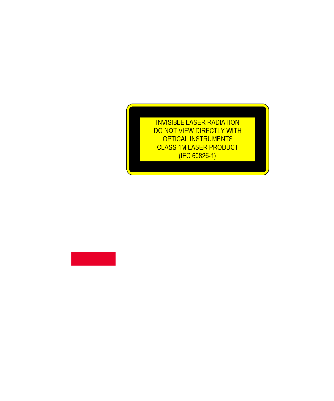
Laser Safety Labels
Laser Class 1M Label
Figure 1 Laser Class 1M Label
A sheet of laser safety labels is included with the laser instrument. In order
to meet the requirements of IEC 60825-1:2014, we recommend that you
stick the laser safety labels, in your language, onto a suitable location on
the outside of the instrument where they are clearly visible to anyone using
the instrument.
Please pay attention to the following laser safety warning:
Under no circumstances look into the end of an optical cable attached to
the optical output when the instrument is operational. The laser radiation
can seriously damage your eyesight. Do not enable the laser when there
is no fiber attached to the optical output connector. The laser can be
enabled by pressing the “active” button close to the optical output
connector on the front panel of the instrument or by remote control. The
laser is on when the green LED, above the optical output, on the front
panel of the instrument is lit. The use of optical instruments with this
product will increase eye hazard. The laser instrument has a built-in
safety circuitry which will disable the optical output in the case of a fault
condition. Refer servicing only to qualified and authorized personnel.
16 Keysight N777-C Series Tunable Laser Family User’s Guide
Page 17
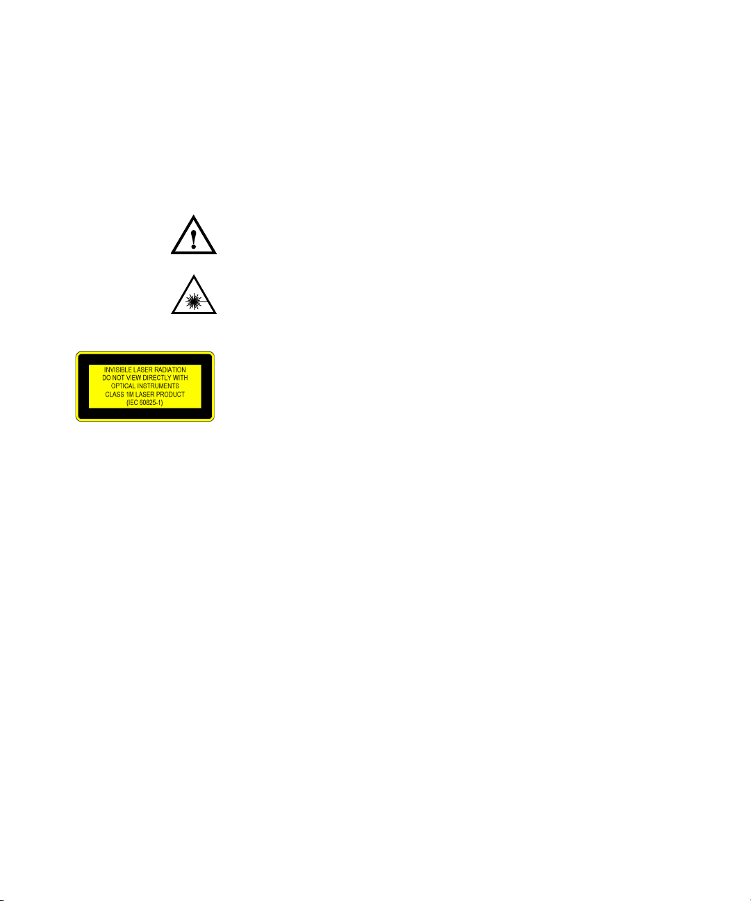
Laser Safety Symbols
The apparatus will be marked with this symbol when it is necessary for the
user to refer to the instruction manual in order to protect the apparatus
against damage.
Hazardous laser radiation.
Invisible laser radiation.
General Operating Considerations 1
Keysight N777-C Series Tunable Laser Family User’s Guide 17
Page 18

1 General Operating Considerations
WARNING
Operating Environment
Overview
In order for the instrument to meet specifications, the operating
environment must be within these limits. Refer to Safety Summary on
page 3.
The instrument is not designed for outdoor use. To prevent potential fire
or shock hazard, do not expose the instrument to rain or other excessive
moisture.
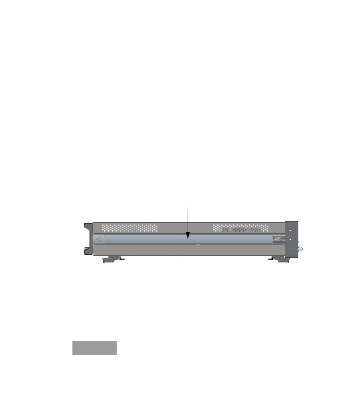
Instrument Cooling
The instrument has a cooling fan mounted internally.
Mount or position your instrument upright and horizontally, as shown in
the following figure so that air can circulate through it freely.
18 Keysight N777-C Series Tunable Laser Family User’s Guide
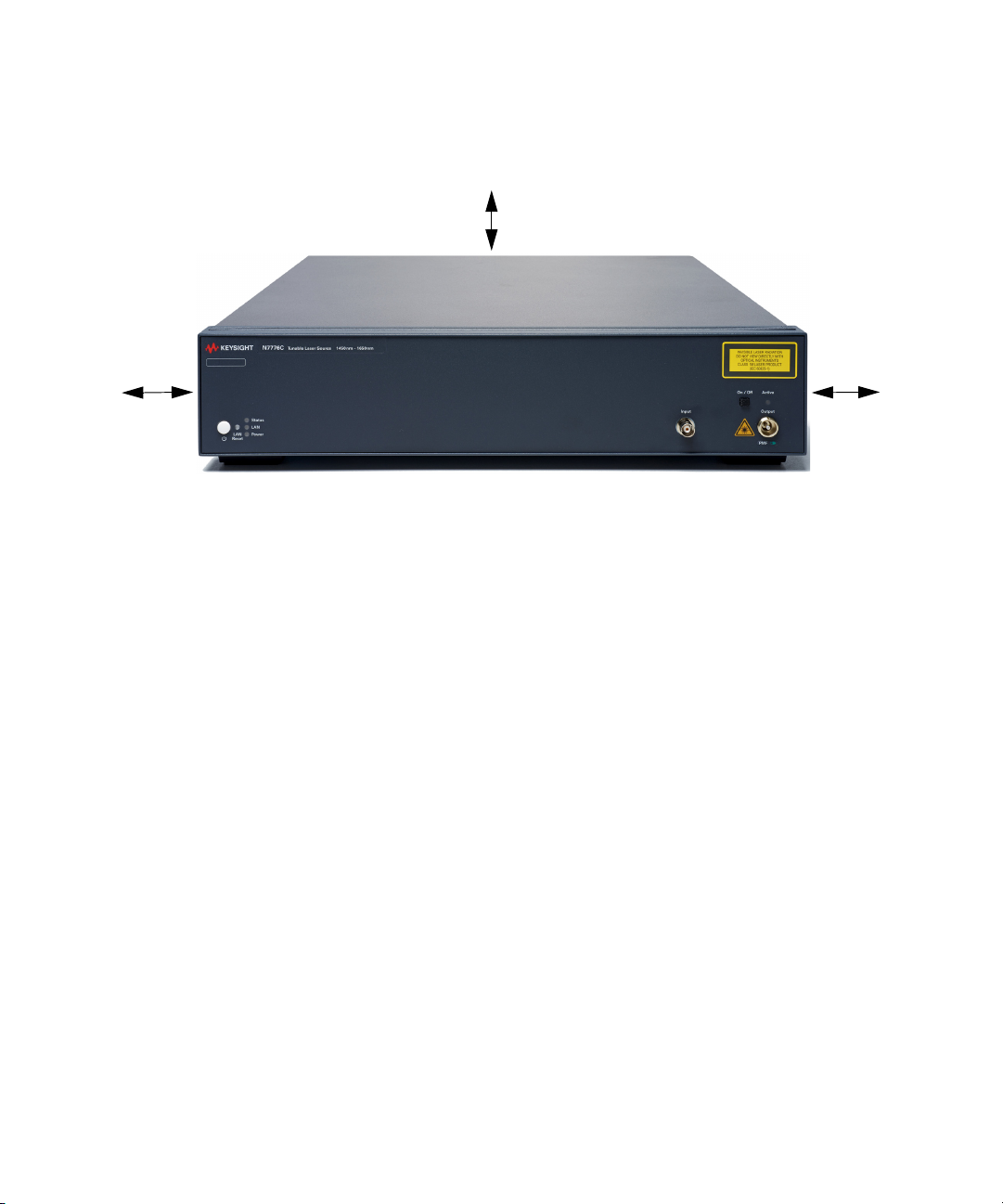
Operating Position
When operating the instrument choose a location that provides at least
75 mm (3 inches) of clearance at the rear, and at least 25 mm (1 inch) of
clearance at each side. Failure to provide adequate air clearance may
result in excessive internal temperature, reducing instrument reliability.
The instrument should not be operated when resting on its rear or side
panels.
Figure 2 shows the correct operating position of Keysight N777-C
instrument.
Page 19
General Operating Considerations 1
25 mm
(1 inch)
25 mm
(1 inch)
75 mm
(3 inches)
Figure 2 Operating Position of the Instrument
Keysight N777-C Series Tunable Laser Family User’s Guide 19
Page 20
1 General Operating Considerations
Strap
NOTE
Handling the Instrument
Storage and Shipment
Carrying the Instrument
Lasers can be stored or shipped at temperatures between –40 °C to +70 °C
(Option D00, standard front panel) and between –30 °C to +70 °C (Option
D01, touchscreen display). Protect the laser from temperature extremes
that may cause condensation within it.
The Keysight N777-C Tunable Laser System can be stored either in its
operating position or on its back legs. The back legs protect the
connectors on the back panel from damage.
Grasp the strap to carry the instrument.
Figure 3 Carrying an Instrument
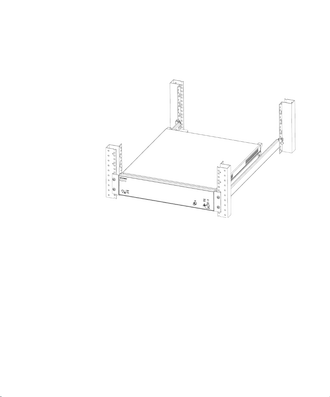
Rack Mount the Instrument
You can mount the instrument in a standard 19-inch rack cabinet using an
optional kit, which includes instructions and mounting hardware.
Remove the carrying strap, and the front and rear rubber bumpers feet,
before mounting the instrument in a rack.
20 Keysight N777-C Series Tunable Laser Family User’s Guide
Page 21
General Operating Considerations 1
To rack mount a single instrument, order adapter kit N7799C-2CM.
Figure 4 shows an example where an instrument is mounted on a rack:
Figure 4 Instrument Mounted on a Rack
Keysight N777-C Series Tunable Laser Family User’s Guide 21
Page 22

1 General Operating Considerations
Obtaining Source Code
This product uses open source packages. To the extent required by the
applicable open source license(s), Keysight makes source code available
upon request. To request source code, please contact Keysight Support at
www.keysight.com/main/support.jspx.
Third party software acknowledgments and licenses for the N777-C series
with the embedded Linux operating system are located at:
www.keysight.com/find/N7776C
.
22 Keysight N777-C Series Tunable Laser Family User’s Guide
Page 23

Keysight N777-C Series Tunable Laser Family
User’s Guide
2 Getting Started
Initial Inspection / 24
Power Supply Requirements / 26
N777-C Series of Tunable Laser Family / 28
N777-C Front and Rear Panel / 30
LAN Interface / 34
Powering Up the Instrument / 36
Connecting the Instrument / 37
N777-C User Interface / 41
Page 24

2 Getting Started
WARNING
Initial Inspection
Initial Inspection
Claims and Repackaging
Inspect the shipping container for damage. If there is damage to the
container or cushioning, keep them until you have checked the contents of
the shipment for completeness and verified the instrument both
mechanically and electrically.
The Performance Tests give procedures for checking the operation of the
instrument. If the contents are incomplete, mechanical damage or defect
is apparent, or if an instrument does not pass the operator’s checks, notify
the nearest Keysight Technologies Sales/Service Office.
You MUST return malfunctioning instruments to a Keysight Technologies
Sales/Service Center for repair and calibration.
If physical damage is evident or if the instrument does not meet
specification when received, notify the carrier and the nearest Keysight
Technologies Sales/Service Office. The Keysight Technologies Sales/
Service Office will arrange for repair or replacement of the unit without
waiting for settlement of the claim against the carrier.
Return Shipments to Keysight Technologies
If the instrument is to be shipped to an Keysight Technologies Sales/
Service Office, attach a tag showing owner, return address, model number
and full serial number and the type of service required.
The original shipping carton and packing material may be reusable, but
the Keysight Technologies Sales/Service Office will provide information
and recommendations on materials to be used if the original packing is no
longer available or reusable. General instructions for repackaging are as
follows:
• Wrap instrument in heavy paper or plastic.
• Use strong shipping container. A double wall carton made of
350-pound test material is adequate.
24 Keysight N777-C Series Tunable Laser Family User’s Guide
Page 25

• Use enough shock absorbing material (3 to 4 inch / 7.5 to 10 cm layer)
• Seal shipping container securely.
• Mark shipping container FRAGILE to encourage careful handling.
• In any correspondence with Keysight, refer to the instrument by model
Deleting User Data
If you need to delete all your logged data and user configurations, press
and hold the LAN Reset button (approx. 5 seconds) to reset the instrument
and all your logged data and user configurations will be deleted.
Getting Started 2
around all sides of the instrument to provide a firm cushion and prevent
movement inside container. Protect control panel with cardboard.
number and serial number.
Keysight N777-C Series Tunable Laser Family User’s Guide 25
Page 26

2 Getting Started
CAUTION
Power Supply Requirements
Line Power Requirements
Line Power Requirements
Line Power Cable
The instrument complies with Overvoltage Category II and can operate
from the single-phase AC power source that supplies between 100 V and
240 V at a frequency in the range 50/60 Hz. The maximum voltage
fluctuation is 10% of the nominal supply voltage. The maximum power
consumption is 200 VA with all options installed.
In accordance with international safety standards, the instrument has a
three-wire power cable. When connected to an appropriate AC power
receptacle, this cable earths the instrument cabinet.
Please note that the switch on the front panel of the instrument does not
stop the flow of power to the instrument.
If you need to turn off the power, unplug the instrument at the mains or
remove the power cable connector from the appliance coupler at the rear
of the instrument. For this reason, the power cable connection should be
easily accessible - allowing you to turn off the power quickly. If the
instrument is in a cabinet, it must be disconnected from the line power
by the system’s line power switch.
26 Keysight N777-C Series Tunable Laser Family User’s Guide
The power switch allows you to switch between stand-by mode and
power-on mode.
Figure 5 Power LED on the Front Panel of the Instrument
Page 27
Getting Started 2
When the instrument is in stand-by mode, the Power LED is orange. When
the instrument is powered-on, the Power LED is green.
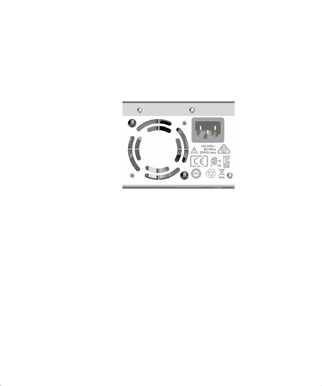
The AC power requirements are summarized on the rear panel of the
instrument.
Figure 6 AC Power Requirement Markings
Keysight N777-C Series Tunable Laser Family User’s Guide 27
Page 28

2 Getting Started
N777-C Series of Tunable Laser Family
The Keysight Technologies N777-C Family of Tunable Laser Sources offers
the full wavelength range from 1240 nm to 1650 nm with no wavelength
gaps.
The N777-C tunable laser sources realize the cost efficiency and
performance required to test components for coarse and dense
wavelength division multiplexing (CWDM, DWDM, 100GBASE-LR4) and
passive optical networks (PON). Whether you need to verify the design of
demanding optical components or adjust more wavelength-selective
switches per hour, or you simply need a stable, tunable optical source, the
N777-C family of tunable lasers offers a suitable model.
All N777-C models are based on a common cavity and laser instrument
design and share a narrow linewidth, excellent long-term stability and low
spontaneous emission level. They are software compatible with the
8160xA and 81600B lasers, the industry standards for more than a decade,
but occupy 1 height unit less rack space.
For further details on its features, application and specifications, refer to
the product datasheet available on www.keysight.com.
28 Keysight N777-C Series Tunable Laser Family User’s Guide
The Keysight N7776C Top-Line Tunable Laser Source
The new Keysight N7776C top line tunable laser source is designed to
reach best-in-class accuracy and sub-picometer repeatability in static and
swept operation for outstanding test efficiency.
With the product family’s lowest spontaneous emission level, the N7776C
enables the validation of extremely deep filters. It also offers the best
wavelength accuracy in the family – enabled by its high-resolution
wavelength reference unit that provides real-time tracking and control and
includes a gas cell for excellent long-term stability and self-adjustment
capability.
The Keysight N7778C Value Line Tunable Laser Sources
The new N7778C value line tunable laser source offers a peak output
power of more than +12 dBm, at least 75 dB/nm above its spontaneous
emission level. It features a typical wavelength repeatability of ±1.5 pm at
two-way sweeps up to 200 nm/s. The N7778C’s balance of features,
performance and price makes it suitable for cost-effective,
high-throughput manufacturing-floor component testing as well as for
coherent transmission experiments.
Page 29

The Keysight N7779C Basic Line Step-Tunable Laser Source
The new N7779C basic line tunable laser source, like the other new
N777-C models, can step quickly to discrete wavelengths with a resolution
of 0.1 pm and a typical wavelength repeatability of ±3 pm, making it ideal
for cost-effective testing of broadband optical devices. With wavelength
setting times like 300 ms, rapid stepped sweeps are possible. Like the
other lasers in the N777-C family, it delivers more than +12 dBm peak
output power with low spontaneous emission levels. At ±0.01 dB power
stability over an hour, it can also serve as a static local oscillator with a
wide tuning range for receiver testing or transmission experiments.
O-band option for Silicon Photonics/ Integrated Photonics Applications
The N777-C option 113 covers the wavelength range from 1240 nm to
1380 nm for an important set of applications. Equipped with PMF output
fiber, these are a good match for testing and developing components with
Silicon Photonics technology. Verifying the spectral responsivity and the
sensitivity of receiver optical subassemblies (ROSA) for 100G Ethernet
benefit from more than +10 dBm output power - enough to allow for
external modulation in BER testing. Combined with very low SSE levels,
Option 113 is ideal for testing wavelength filters for LR4 components.
Getting Started 2
E-band option for CWDM8 Component Testing
The N777-C option 114 covers the wavelength range from 1340 nm to
1495 nm. Combined with the other options, this allows measurements
over all CWDM channels, such as for CWDM8 devices. Components for
Raman amplification also use this wavelength range.
Keysight N777-C Series Tunable Laser Family User’s Guide 29
Page 30
2 Getting Started
N777-C Front and Rear Panel
This section provides information on the front and rear panels of the
N777-C Series Tunable Laser Source.
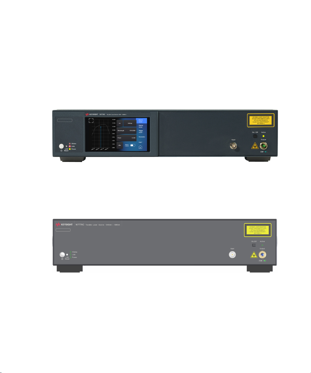
Figure 7 shows the front panel of the N777-C Series Tunable Laser Source
with the optional display unit (Option D01):
Figure 7 Front Panel of the N777-C Instrument with Display
30 Keysight N777-C Series Tunable Laser Family User’s Guide
Figure 8 shows the front panel of the N777-C Series Tunable Laser Source
without the display (Option D00):
Figure 8 Front Panel of the N777-C Instrument without Display
Page 31

Figure 9 shows the rear panel of the N777-C Series Tunable Laser Source:
CAUTION
CAUTION
Figure 9 Rear Panel of the N777-C Instrument
Input/Output Signals
Front Panel:
There is one BNC input connector on the front panel of the Keysight
N777-C.
Getting Started 2
Keysight N777-C Series Tunable Laser Family User’s Guide 31
An absolute maximum of ±5 V can be applied as an external voltage to
the BNC connector.
Rear Panel:
There is one input BNC connector: Trigger In. This is a TTL input.
A maximum of 5 V can be applied as an external voltage to this input
connector.
There is one output BNC connector: Trigger Out. This is a TTL output. Do
not apply an external voltage to this connector.
Do not connect multiple Trigger Outputs together.
Page 32

2 Getting Started
E
H
Slow Axis (Polarization Axis)
Connector Key
Fiber Cladding
Fiber Core
(9-μm Diameter)
Stress Rods
Not to Scale
Optical Output
Polarization Maintaining Fiber
All Keysight N777-C Series Tunable Laser Family instruments include
polarization maintaining fiber (PMF) outputs, aligned to maintain the state
of polarization.
The fiber is of Panda type, with TE mode in the slow axis in line with the
connector key. A well-defined state of polarization ensures constant
measurement conditions.
Figure 10 PMF Output Connector
Angled Contact Connectors
32 Keysight N777-C Series Tunable Laser Family User’s Guide
The N777-C Series Tunable Laser instruments are outfitted with an angled
polished connector. Angled contact connectors help you to control return
loss. With angled fiber end-faces, reflected light tends to reflect into the
cladding, reducing the amount of light that reflects back to the source.
When reflected light remains in the fiber core at two or more locations
along the optical path, such as at an open straight-polished connector
output to a power meter, double reflections result in multi-path
interference of the coherent light and thus power instability in the
measurements.
Page 33

Getting Started 2
CAUTION
Straight Contact
Connector Symbol
Angled Contact
Connector Symbol
NOTE
Since the contact connector on your instrument is angled, you can only
use cables with angled connectors at the instrument.
Figure 11 Angled and Straight Contact Connector Symbol
Figure 11 shows the symbols that tell you whether the contact connector
of your instrument is angled or straight. The angled contact connector
symbol is colored green.
You should connect straight contact fiber end connectors with neutral
sleeves to straight contact connectors and connect angled contact fiber
end connectors with green sleeves to angled contact connectors.
Keysight N777-C Series Tunable Laser Family User’s Guide 33
You cannot connect angled non-contact fiber end connectors with
orange sleeves directly to the instrument.
Page 34

2 Getting Started
Red LAN
No LAN link
Yellow LAN Green LAN
No IP Addr ess
LAN li nk
LAN li nk
LAN Interface
The LAN LED
When the LAN connection is made, you will see the following indicators:
There may be a delay between making the LAN link (yellow status) and
getting the IP address (green status). This delay may be longer if there is
no DHCP server, for example when the instrument is connected directly to
a PC.
The LAN Reset button
This recessed button has two functions.
• Pressing the button briefly invokes a preset of the instrument and
restores default measurement settings. This is equivalent to the
programming command:
:SYSTem:PRESet
• Pressing and holding the button for 5 seconds will reset the LAN
parameters to the factory default. This includes removing the password.
This is equivalent to the following sequence of programming command:
:SYSTem:COMMunicate:ETHernet:RESet
34 Keysight N777-C Series Tunable Laser Family User’s Guide
Page 35

USB Interface
NOTE
USB Type-B Connector
Getting Started 2
It is recommended to use the Keysight IO Libraries Suite to enable
instrument communication for a variety of development environments.
It is available at: http://keysight.com/find/iolibs
The instrument is a USB device, with a USB Type-B connector which is
available on the rear side of the instrument.
Keysight N777-C Series Tunable Laser Family User’s Guide 35
Page 36

2 Getting Started
Powering Up the Instrument
When you power on the instrument, the LEDs on the front panel show the
various stages of the instrument.
Power LAN Status
Yellow Standby mode Searching for LAN Warming Up
Green ON Connected with LAN
Blinking Green Communicating
Red Not connected
over LAN / USB
36 Keysight N777-C Series Tunable Laser Family User’s Guide
Page 37

Connecting the Instrument
Connecting over USB
Getting Started 2
1 Power on the instrument.
2 Connect the PC to the instrument using a USB cable.
3 The operating system will detect and display the new instrument as a
new drive.
4 Double-click on this new drive. It will show a shortcut to start the user
interface.
5 Double -click on this shortcut. This will open the user interface of the
instrument in a browser.
Keysight N777-C Series Tunable Laser Family User’s Guide 37
Page 38

2 Getting Started
Connecting over LAN
1 Make sure the instrument is connected to the LAN, and that the LAN
LED on the front panel is green.
2 If it is not already running, start the Keysight Connection Expert
software.
The Discovery Service automatically discovers LAN instruments on the
same subnet as the PC on which the service is running.
3 To add LAN instruments to the Connection Expert My Instruments list:
a Click, select LAN Instrument from the context list. This opens the list
of discovered LAN instruments.
b Click the check box for each instrument you want to add to the list.
c Click OK.
38 Keysight N777-C Series Tunable Laser Family User’s Guide
Page 39

Getting Started 2
4 To manually add LAN instruments outside of the local subnet:
a Click, select LAN Instrument from the context list. This opens the list
of discovered LAN instruments.
b Click the Enter Address tab.
c Enter the LAN address or host name and select the protocol used to
communicate with the instrument. Supported protocols are VXI-11
and Socket.
d Click OK.
Keysight N777-C Series Tunable Laser Family User’s Guide 39
Page 40

2 Getting Started
5 Linux or macOS can use the zeroconf / mdns discovery service with
tools like Avahi (GNU/Linux) or Bonjour (Mac).
40 Keysight N777-C Series Tunable Laser Family User’s Guide
Page 41

N777-C User Interface
Getting Started 2
Keysight offers the N777-C Tunable Laser Source instruments with an
optional display. Figure 12 shows the user interface accessed in the
instrument’s display:
Figure 12 N777-C Instrument User Interface
For details on the interface and how to access and use it, see Chapter ,
“N777-C Instrument’s Front Panel Display,” on page 85.
Keysight N777-C Series Tunable Laser Family User’s Guide 41
Page 42
2 Getting Started
Figure 13 shows the web interface of the N777-C (Option D00) non-display
instruments where the user interface can be used in a web browser on
your computer.
Figure 13 N777-C Web Interface
For details on the web interface and how to use it, see Chapter , “N777-C
Web Interface Reference,” on page 59.
42 Keysight N777-C Series Tunable Laser Family User’s Guide
Page 43

Keysight N777-C Series Tunable Laser Family
User’s Guide
3 Definition of Terms
General Definitions / 44
Absolute wavelength accuracy (continuous sweep mode) / 45
Absolute wavelength accuracy (stepped mode) / 45
Dynamic power reproducibility (continuous sweep mode) / 45
Dynamic relative power flatness (continuous sweep mode) / 46
Effective linewidth / 46
Linewidth / 47
Maximum output power / 47
Mode-hop free tunability / 48
Operating temperature and humidity / 48
Output isolation / 48
Polarization extinction ratio / 48
Power flatness versus wavelength / 49
Power linearity / 50
Power repeatability / 50
Power stability / 51
Relative intensity noise (RIN) / 51
Relative wavelength accuracy (continuous sweep mode) / 52
Relative wavelength accuracy (stepped mode) / 52
Return loss / 53
Side-mode suppression ratio / 53
Signal to source spontaneous emission (SSE) ratio / 54
Signal to total source spontaneous emission ratio / 55
Wavelength range / 55
Wavelength repeatability (continuous sweep mode) / 55
Wavelength repeatability (stepped mode) / 56
Wavelength resolution / 57
Wavelength stability / 57
Page 44

3 Definition of Terms
NOTE
Definition of Terms
General Definitions
This section defines terms that are used in this document and in the data
sheet.
Measurement principles are indicated. Alternative measurement principles
of equal value are also acceptable.
Constant Temperature
Where required, is a stable operating temperature within ±1 K.
Logged wavelength
This is the wavelength measured and recorded by the internal wavelength
meter during a sweep at the corresponding trigger signal. This recorded
wavelength can be read with the logging function.
The logged wavelength positions during a sweep depend on
environmental conditions and may differ slightly between repeated
sweeps.
Stepped mode
In stepped mode the tunable laser source is operated statically, so that a
user's measurement is made at a fixed wavelength of the tunable laser
source. When tuning to a new wavelength, the static specifications are
valid after completion of the tuning operation.
Continuous sweep mode
In continuous sweep mode the tunable laser source is operated
dynamically, so that a user's measurement is made while the wavelength
of the tunable laser source changes in a defined way (given by start
wavelength, end wavelength and sweep speed). During a continuous
sweep the dynamic specifications and the
44 Keysight N777-C Series Tunable Laser Family User’s Guide
“Logged wavelength“ apply.
Page 45

Absolute wavelength accuracy (continuous sweep mode)
Definition of Terms 3
The maximum difference between the
wavelength in “Continuous sweep mode“. Wavelength is defined as
wavelength in vacuum.
Figure 14 Absolute wavelength accuracy (continuous sweep mode)
Conditions: As specified. No mode-hop.
Absolute wavelength accuracy (stepped mode)
The maximum difference between the displayed wavelength and the actual
wavelength of the tunable lase source. Wavelength is defined as
wavelength in vacuum.
Conditions: Constant power level. Other conditions as specified.
Measurement: Using a wavelength meter, averaging time
“Logged wavelength“ and the actual
≥ 1s.
Dynamic power reproducibility (continuous sweep mode)
Specifies the random uncertainty in reproducing the output power at the
same actual wavelength in different sweeps. It is expressed as ± half the
span between the maximum and minimum of all actual output powers.
Keysight N777-C Series Tunable Laser Family User’s Guide 45
Page 46

3 Definition of Terms
Figure 15 Dynamic power reproducibility (continuous sweep mode)
Conditions: Uninterrupted tunable laser source output power, constant temperature,
no mode-hop. Other conditions as specified.
Dynamic relative power flatness (continuous sweep mode)
The high frequency part of the dynamic power flatness, obtainable by
referencing the power measured at high sweep speed to the power
measured at low sweep speed.
Conditions: Uninterrupted tunable laser source output power, constant power setting,
constant temperature, no mode-hop. Other conditions as specified.
Measurement: Reference sweep speed value 0.5 nm/s.
Effective linewidth
The time-averaged 3 dB width of the optical spectrum, expressed in Hertz.
Conditions: Coherence control on. Other conditions as specified.
Measurement: Using a heterodyning technique: The output of the laser under test is
mixed with another laser of the same type on a wide bandwidth
photo-detector. The electrical noise spectrum of the photo-detector
current is measured with a Lightwave signal analyzer, and the line-width
calculated from the heterodyne spectrum. (Lightwave signal analyzer
settings: resolution bandwidth 1 MHz, video bandwidth 10 kHz,
sweep time 20 ms, single scan).
46 Keysight N777-C Series Tunable Laser Family User’s Guide
Page 47

Definition of Terms 3
Linewidth
The 3 dB width of the optical spectrum, expressed in Hertz.
Conditions: Coherence control off. Other conditions as specified.
Measurement: Using a self-heterodyning technique: The output of the laser under test is
sent through a Mach-Zehnder interferometer in which the length
difference of the two arms is longer than the coherence length of the laser.
The electrical noise spectrum of the photo-detector current is measured
using a Lightwave signal analyzer or Keysight Optical Modulation Analyzer,
and the linewidth calculated from the heterodyne spectrum.
Alternatively, Using a heterodyning technique: The output of the laser
under test is mixed on a wide bandwidth photo-detector with another laser
of the same type or with a laser with a line-width much lower than the
laser to be measured. The electrical noise spectrum of the photo-detector
current is measured using a Lightwave signal analyzer or Keysight Optical
Modulation Analyzer, and the linewidth calculated from the heterodyne
spectrum.
Maximum output power
The maximum achievable output power of the tunable laser source and the
maximum output power for which the tunable laser source specifications
apply.
Figure 16 Maximum Output Power vs Wavelength, Maximum
Conditions: As specified.
Keysight N777-C Series Tunable Laser Family User’s Guide 47
Flat Output Power vs Wavelength
Page 48

3 Definition of Terms
NOTE
Mode-hop free tunability
Operating temperature and humidity
Measurement: Using a power meter at the end of a 2 m single-mode fiber patchcord.
Specifies the wavelength range for which no abrupt wavelength change
occurs in Stepped mode.
The ambient temperature range and humidity range of the tunable laser
source for which the specifications apply.
If the instrument is rack-mounted, the temperature and humidity within
the rack apply.
48 Keysight N777-C Series Tunable Laser Family User’s Guide
Output isolation
The insertion loss of the built-in isolator in the backward direction.
Measurement: This characteristic cannot be measured from outside the instrument. It is
based on known isolator characteristics.
Polarization extinction ratio
Specifies the ratio of the optical power in the slow axis of a connected
polarization-maintaining fiber to optical power in the fast axis, expressed
in dB
Measurement: Using a polarization analyzer at the end of a polarization-maintaining
patchcord, by sweeping the wavelength to create circular traces on the
Poincaré sphere. Calculate the polarization extinction ratio from the
diameters of these circles.
Page 49

Definition of Terms 3
Figure 17 Circular traces on the Poincaré sphere used to calculate
polarization extinction ratio.
Power flatness versus wavelength
Specifies ± half the span (in dB) between the maximum and the minimum
actual power levels of the tunable laser source when changing the
wavelength.
Figure 18 Power flatness vs. wavelength.
Conditions: Uninterrupted tunable laser source output power, constant power setting,
constant temperature. Other conditions as specified.
Keysight N777-C Series Tunable Laser Family User’s Guide 49
Page 50

3 Definition of Terms
NOTE
Power linearity
When measuring the ratios (in dB) between the displayed power level and
the actual power level for different output power levels of the tunable laser
source, the power linearity is ± half the difference between the maximum
and the minimum value of all ratios.
Figure 19 Power linearity.
Conditions: Uninterrupted tunable laser source output power, constant wavelength
setting, constant temperature. Other conditions as specified.
Power repeatability
The uncertainty in reproducing the power level after changing and
re-setting the power level. The power repeatability is ± half the span
between the highest and lowest actual power.
Conditions: Uninterrupted tunable laser source output power, constant wavelength
setting, constant temperature. Other conditions as specified.
The long-term power repeatability can be obtained by taking the power
repeatability and power stability into account.
50 Keysight N777-C Series Tunable Laser Family User’s Guide
Page 51

Power stability
Definition of Terms 3
Specifies the change of the power level of the tunable laser source over
time, expressed as ± half the span (in dB) between the highest and lowest
actual power.
Figure 20 Power stability.
Conditions: Time span as specified. Uninterrupted tunable laser source output power,
constant wavelength and power level settings, constant temperature.
Other conditions as specified.
Relative intensity noise (RIN)
Specifies the ratio between the mean-square of the optical power
fluctuation amplitude
bandwidth B, and the square of the average optical power P
RIN, if expressed as "dB/Hz", is calculated by:
Keysight N777-C Series Tunable Laser Family User’s Guide 51
ΔP
within a specified frequency range f and for
f,B
avg
.
Page 52

3 Definition of Terms
Relative wavelength accuracy (continuous sweep mode)
Conditions: As specified.
Measurement: Using a Lightwave signal analyzer and bandwidth set to 3 MHz.
When measuring the differences between the actual and Logged
wavelength in Continuous sweep mode, the dynamic wavelength accuracy
is ± half the span between the maximum and the minimum value of all
differences.
Figure 21 Relative wavelength accuracy (continuous sweep mode).
Conditions: As specified. No mode-hop.
Relative wavelength accuracy (stepped mode)
When randomly changing the wavelength and measuring the differences
between the displayed and the actual wavelength, the relative wavelength
accuracy is ± half the span between the maximum and the minimum value
of all differences.
52 Keysight N777-C Series Tunable Laser Family User’s Guide
Page 53

Definition of Terms 3
Figure 22 Relative wavelength accuracy.
Conditions: Uninterrupted tunable laser source output power, constant power setting,
constant temperature. Other conditions as specified.
Measurement: Using a wavelength meter, averaging time
Return loss
Specifies the ratio of the optical power incident to the tunable laser source
output port at the wavelength set on the tunable laser source, to the
power reflected from the tunable laser source output port.
Conditions: Tunable laser source output off.
Side-mode suppression ratio
The ratio of optical power in the main mode to the optical power of the
highest sidemode, expressed in dB:
Conditions: As specified.
≥ 1s.
Keysight N777-C Series Tunable Laser Family User’s Guide 53
Page 54

3 Definition of Terms
Signal to source spontaneous emission (SSE) ratio
Measurement: Using the Lightwave signal analyzer, by analyzing the heterodyning
between the main signal and the highest side mode within 0.1 GHz to
6GHz.
Specifies the ratio between signal power and maximum spontaneous
emission (SSE) power. The SSE power is determined in a specified
bandwidth within a ±3 nm window around the signal wavelength, where
±1 nm around the signal wavelength are excluded, expressed in dB per
specified bandwidth.
Figure 23 Signal to source spontaneous emission ratio.
Conditions: Output power as specified. Other conditions as specified.
Measurement: Using an optical spectrum analyzer (OSA) at 0.5 nm resolution bandwidth
(to address the possibility of higher SSE within a narrower bandwidth),
then extrapolated to 1 nm bandwidth. For the low-SSE output, if
applicable, with a fiber Bragg grating inserted between the tunable laser
source and the OSA to suppress the signal, thereby enhancing the
dynamic range of the OSA.
54 Keysight N777-C Series Tunable Laser Family User’s Guide
Page 55

Signal to total source spontaneous emission ratio
The ratio of signal power to total spontaneous emission power within,
expressed in dB. The total spontaneous emission power is measured over
the specified Wavelength range.
Figure 24 Signal to total source spontaneous emission ratio.
Definition of Terms 3
Conditions: Output power as specified. Other conditions as specified.
Measurement: Using an optical spectrum analyzer, by integrating the source
spontaneous emission and excluding the remnant signal. For the low-SSE
output, if applicable, with a fiber Bragg grating inserted between the
tunable laser source and the OSA to suppress the signal, thereby
enhancing the dynamic range of the OSA.
Measurement principles are indicated. Alternative measurement principles of equal value are also acceptable.
Wavelength range
The range of wavelengths for which the specifications apply (if not
otherwise stated).
Wavelength repeatability (continuous sweep mode)
The random uncertainty of the nominal wavelength of the tunable laser
source at any fixed actual wavelength in repeated sweeps. The nominal
wavelength of the tunable laser source is derived from the (discrete)
Keysight N777-C Series Tunable Laser Family User’s Guide 55
Page 56

3 Definition of Terms
NOTE
Logged wavelength by interpolation. The repeatability is expressed as ±
half the span between the maximum and the minimum value of all nominal
values.
Figure 25 Wavelength repeatability (continuous sweep mode).
Conditions: As specified. No mode-hop.
Measurement: Using an optical power meter and by performing repeated spectral loss
measurement on a stable absorption peak from a reference component,
then analyzing the variation of the determined (interpolated) wavelength of
the peak.
Wavelength repeatability (stepped mode)
The random uncertainty in reproducing a wavelength after changing and
re-setting the wavelength. The wavelength repeatability is ± half the span
between the maximum and the minimum of all actual values of this
wavelength.
Conditions: Uninterrupted tunable laser source output power, constant power level,
constant temperature. Other conditions as specified.
Measurement: Using a wavelength meter, averaging time
≥ 1s.
The wavelength repeatability of the low-SSE output (if applicable) is the
same as the wavelength repeatability of the high power output
(guaranteed by design).
56 Keysight N777-C Series Tunable Laser Family User’s Guide
Page 57

Definition of Terms 3
NOTE
The long-term wavelength repeatability can be obtained by taking the
wavelength repeatability and wavelength stability into account.
Wavelength resolution
The smallest selectable wavelength increment or decrement.
Wavelength stability
Specifies the change of the actual wavelength of the tunable laser source
over time, expressed as ± half the span between the maximum and
minimum of all wavelengths.
Conditions: Time span as specified, uninterrupted tunable laser source output power,
constant wavelength and power level settings, constant temperature.
Other conditions as specified.
Measurement: Using a wavelength meter, averaging time
Keysight N777-C Series Tunable Laser Family User’s Guide 57
≥ 1s.
Page 58

Page 59

Keysight N777-C Series Tunable Laser Family
User’s Guide
4 N777-C Web
Interface Reference
N777-C Web Interface / 60
Controlling N777-C Instruments / 62
How to Use Auxiliary Functions / 74
Page 60

4 N777-C Web User Interface Reference
N777-C Web Interface
Figure 26 shows the N7776C web interface with various tabs highlighted.
The same web interface is applicable for N7778/79C instruments.
Figure 26 N7776C Web Interface
The N777-C web interface has the various tabs that help the user to
control the instruments:
• Home – This tab displays the various instrument settings. For details,
refer How to Get Current Instrument Settings? on page 74.
• Control Instrument – This tab allows you to set the parameters to
control the instrument. For details, refer to Controlling N777-C
Instruments on page 62.
• Get Image – This tab allows you to capture a screen of the Control
Instrument window. The image is saved in PNG format in your PC. For
details, see How to Capture an Image of the Graph? on page 75.
60 Keysight N777-C Series Tunable Laser Family User’s Guide
Page 61

N777-C Web User Interface Reference 4
• Configure LAN – This tab displays the current LAN configuration. In
addition, this tab also allows you to edit the current LAN configuration.
For details, refer to How to Configure LAN? on page 80.
• Help – This tab opens the instrument help.
Keysight N777-C Series Tunable Laser Family User’s Guide 61
Page 62

4 N777-C Web User Interface Reference
Controlling N777-C Instruments
Control Instrument Tab
The Control Instrument tab is used to control the N777-C instruments:
The Control Instrument tab provides the following features:
Display Wavelength and Power
Displays the instrument’s current wavelength and power.
62 Keysight N777-C Series Tunable Laser Family User’s Guide
Page 63

Changing Wavelength, Power and Units
Left/Right Arrows
Up/Down Arrows
Changing Wavelength
Changing Unit
Allows you to change the instrument’s current wavelength, power and
their respective units. The procedure for changing wavelength, power and
their units are similar. The following example provides steps to change the
wavelength and its unit.
1 Click on the wavelength button.
2 Use the left or right arrows to move the position of the cursor pointer
either to the left or right.
3 Use the up or down arrows to increase or decrease the wavelength.
4 Click on the unit button to change the unit. The allowed units for
Wavelength are nm and THz. The allowed units for Power are mW
and dBm.
N777-C Web User Interface Reference 4
Wavelength Vs. Power Graph
The Control Instrument tab displays a graph that shows the relationship
between the wavelength and power. The power is represented by x axis
while the Y axis represents the wavelength.
Keysight N777-C Series Tunable Laser Family User’s Guide 63
Page 64

4 N777-C Web User Interface Reference
You can click on the graph to modify the wavelength and power. The blue
curve on the graph denotes the excessive power curve. Setting an output
power above the maximum power curve is indicated with EXP on the
power display. For details, see How to Avoid Access Power? on page 66.
64 Keysight N777-C Series Tunable Laser Family User’s Guide
Working with Markers
To add a marker, double-click at a point on the graph where you want
to add the marker. A small blue circle on that point denotes the marker.
You are allowed to set multiple markers. Hovering the cursor over the
marker causes the wavelength and power display.
To save the marker, click on the Save Current Markers option.
To remove all saved markers, click on the Remove All Marker option.
Page 65

How to set Wavelength?
How to change the Wavelength
There are three ways to set the wavelength of the Tunable Laser.
• You can set the wavelength directly on clicking the Wavelength button,
•You go the Settings > Measurement Settings and then set the
• You can click on the graph to set a wavelength.
Wavelength Range
Every Tunable Laser instrument has a specified wavelength range. This
range is available for all Tunable Laser instruments. See the Laser Safety
Information on page 15 to find your instrument’s specified range.
Every Tunable Laser instrument has a permitted wavelength range. This
range is greater than the specified range. The permitted wavelength range
varies for each Tunable Laser instrument. You can set the wavelength to
any value within the permitted wavelength range.
N777-C Web User Interface Reference 4
see Changing Wavelength, Power and Units on page 63.
wavelength, or
How to Set Power?
How to change the power
There are three ways of changing the power:
• You can set the power directly on clicking the Power button, see
Changing Wavelength, Power and Units on page 63.
•You go the Settings > Measurement Settings and then set the power,
or
• You can click on the graph to set a power.
How to Set the Power Unit
Pressing the unit button allows you to switch either mW or dBm as the
units in which power is displayed.
What are the Power Units?
Watts (W) are the SI unit for power measurement.
You can also measure power in dBm. Values displayed in these units are
derived from measurement in Watts.
By selecting dBm, the following calculation is made:
Keysight N777-C Series Tunable Laser Family User’s Guide 65
Page 66

4 N777-C Web User Interface Reference
How to Avoid Access Power?
Where,
P
is the power value displayed in dBm, and
dBm
is the input signal level in Watts.
P
input
Power, in units of dBm, is measured relative to 1 mW, it is an absolute
power measurement.
If the text EXP is displayed in power of a Tunable Laser channel, you have
set an output power level that is larger than the laser diode can produce at
the selected wavelength.
To avoid this you can:
• reduce the optical output power,
•click Set Pmax in the Measurement Setting option to select the
highest permissible power for the selected.
•click Set Pmax/Sweep to select the highest permissible power for the
selected wavelength sweep.
How to Perform a Wavelength Sweep?
What is a Wavelength Sweep?
A wavelength sweep is performed when the instrument changes the
optical wavelength of the optical output across a user-defined wavelength
range. You can use a wavelength sweep to measure the
wavelength-dependent loss of an optical component.
66 Keysight N777-C Series Tunable Laser Family User’s Guide
Page 67

How to Set the Wavelength Sweep?
The Sweep Parameters
N777-C Web User Interface Reference 4
These are the parameters for the wavelength sweep:
• Sweep Mode - see How to Perform a Sweep? on page 69,
• Repeat mode - see How to Set the Repeat Mode? on page 68.
• Sweep Speed - the speed of a continuous sweep,
• Cycles - the number of times the sweep is repeated,
• Dwell - the amount of time spent at the wavelength during each step,
for a stepped sweep
• Sweep Start - the wavelength at which the sweep begins,
• Sweep Stop - the wavelength at which the sweep ends,
• Sweep Step - the size of the change in the wavelength for each step of
a sweep,
• Run/Stop Sweep - to run and start the sweep.
Keysight N777-C Series Tunable Laser Family User’s Guide 67
Page 68

4 N777-C Web User Interface Reference
NOTE
For a Continuous sweep, Step sets the wavelength interval between
output triggers, if you have set Output Trigger Mode to Step Finished,
How to Use Output Triggering on page 71.
see
How to Set the Repeat Mode?
68 Keysight N777-C Series Tunable Laser Family User’s Guide
Figure 27 The Parameters for a Stepped Wavelength Sweep
The Repeat Mode determines how the instrument performs a multi-cycle
sweep.
• Select Two way, if you want to start every odd sweep cycle at [λ Start]
and to start each even sweep cycle at [λ Stop].
• Select Oneway, if you want to start every sweep cycle at [λ Start] and to
end every sweep cycle at [λ Stop].
Figure 28 illustrates how these modes work for a three-cycle wavelength
sweep.
Page 69

N777-C Web User Interface Reference 4
NOTE
Figure 28 Repeat Modes
How to Set the Maximum Power for the Sweep Range?
Pressing Set Pmax/Sweep sets the power to the maximum for the
selected sweep range. Pressing Set Pmax/Sweep ensures the power will
be constant for the whole sweep.
How to Perform a Sweep?
There are three sweep modes:
• Stepped - which dwells at wavelengths that are separated by a certain
step size,
• Continuous - which sweeps continually at the speed you set, and
• Manual - which you can run each step manually.
You cannot turn the laser off by pressing the Active hardkey on the
Tunable Laser front panel, while a wavelength sweep is running.
You can press Stop and, then, press the Active hardkey on the Tunable
Laser front panel, to turn off the laser.
Keysight N777-C Series Tunable Laser Family User’s Guide 69
Page 70

4 N777-C Web User Interface Reference
CAUTION
How to Use Triggers?
How to Set the Trigger Configuration
The N777-C Tunable Laser instruments allow you to trigger the instrument
to perform tasks and to output trigger signals to external measurement
instruments.
The trigger level at the external trigger connectors is by default active
high, this means when a trigger rises above the high TTL level (rising
edge), a trigger is accepted.
You can use the Trigger Config drop-down menu to select the triggering
mode. The following trigger configuration modes are available:
1 Disabled - select this mode if you do not want to use triggering. In this
case input and output connectors are disabled.
2 Default - select this mode if you want to enable the trigger connectors.
In this case input and output connectors are active.
3 Passthrough - select this mode if you want an input trigger to
automatically generate an output trigger. This allows you to trigger
another instrument almost simultaneously.
70 Keysight N777-C Series Tunable Laser Family User’s Guide
How to Use Input Triggering
You can configure your N777-C Tunable Laser instrument to perform
certain tasks when you apply a trigger to the Input Trigger Connector.
A maximum of 5 V can be applied as an external voltage to the Input
Trigger connector.
Do not apply an external voltage to these connectors.
Page 71

To set your instrument’s Input Trigger Configuration:
NOTE
1From the Settings > Measurement Settings and select Trigg er.
2 Use the drop-down menu to select the Input Trigger. The following
input trigger options are available:
• Ignore, input triggers are ignored.
• Next Step, an input trigger will cause the next step of a stepped
sweep to be performed.
• Run Sweep, an input trigger will start a single sweep cycle.
3 You can generate input triggers in any of the following ways:
• applying a trigger to the Input Trigger Connector on the rear panel
of your instrument,
• setting Trigger Configuration to Loopback so that an output trigger
automatically generates an input trigger, or
• using the :TRIGger1 command, see your Programming Guide.
How to Use Output Triggering
You can configure your Tunable Laser instrument to output a trigger when
the instrument performs certain tasks.
To set your instrument’s Output Trigger Configuration:
1From the Settings > Measurement Settings and select Trigg er.
2 Use the drop-down menu to select the Output Trigger. The following
output trigger options are available:
• Disabled, the output trigger mode is disabled.
• Step Finished, a trigger is output after every step of a sweep
finishes.
• Sweep Finished, a trigger is output after a sweep cycle finishes.
• Sweep Started, a trigger is output after a sweep cycle starts.
N777-C Web User Interface Reference 4
If you choose Step Finished and a Continuous sweep, the wavelength
interval between hardware triggers is set by the Step parameter,
although, the sweep is not stepped.
How to set Modulation?
Keysight N777-C Series Tunable Laser Family User’s Guide 71
Page 72

4 N777-C Web User Interface Reference
The following modulation modes are available:
• OFF - No modulation
• Coherence - You can use coherence control to increase the line width
of the optical signal output from your Tunable Laser instrument.
Enabling the coherence control increases the line width of the optical
output signal to between 50 and 500 MHz (typically). Coherence
control greatly reduces interference effects and therefore improves the
power stability in sensitive test setups.
The N777-C instruments also allow adjustment of the line width
broadening with the "Coherence Level" setting. A level of 100%
corresponds to minimal broadening. The default level is usually a good
setting.
• Wavelength Locking - You can choose wavelength locking as the
modulation source, so the change in output wavelength is roughly
proportional to the voltage you apply to the input BNC connector on
the front panel of your Tunable Laser instrument.This enables you to
fine tune the output wavelength within a limited wavelength range.
Wavelength locking may exhibit some hysteresis effects. The
wavelength change may differ slightly when you increase voltage from
when you decrease voltage.
If you modulate the input signal, the amplitude of the wavelength
change of the modulated optical output reduces with increasing
modulation frequency.
How to Lock/Unlock the Instrument?
Locking the instrument avoids to turn on the laser of the tunable laser
instruments. This helps in avoiding accidents that are caused due to laser.
To lock a device;
1 On the Control Instrument page, click to Settings > Measurement
Settings and then go to Device Locked option.
72 Keysight N777-C Series Tunable Laser Family User’s Guide
Page 73

2Click on the Device Locked button the lock or unlock the device.
NOTE
Laser OFF Laser ON
Please note that you will be not able to open the device shutter or turn on
the laser until the device is locked.
How to Turn ON/OFF the Laser?
To turn ON/OFF the laser;
1 On the Control Instrument page, click to Settings > Measurement
Settings and then go to Shutter Open option.
2Click on the Shutter Open button the turn ON/OFF the high-power
laser. Ensure that your device is unlocked.
N777-C Web User Interface Reference 4
3 Additionally, you can also click on the Laser ON/OFF button available
on the Control Instrument page.
Keysight N777-C Series Tunable Laser Family User’s Guide 73
Page 74

4 N777-C Web User Interface Reference
NOTE
How to Use Auxiliary Functions
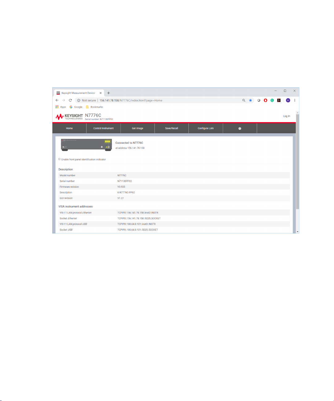
How to Get Current Instrument Settings?
The Home tab on the N777-C web interface displays the current
instrument settings.
This tab displays the following settings:
• Description – Displays the instrument description such as instrument’s
model no., serial no., firmware version and description of the current
instrument.
• VISA Instrument Address – Displays VISA instrument addresses of the
current instrument.
• LAN Details – Displays LAN configuration details of the current
instrument.
Please note that the Home tab does not allow the user to change the
displayed instrument settings.
74 Keysight N777-C Series Tunable Laser Family User’s Guide
Page 75

How to Identity a Particular instrument?
NOTE
Sometimes, you have many instruments mounted on the rack. In this
situation, it becomes difficult to identify a particular instrument which are
currently connected.
To identify a particular instrument, select the check-box Enable front
panel identification indicator available on the N777-C Home tab. The
Status LED on the front panel of the connected instrument will start
flashing.
How to Capture an Image of the Graph?
The Get Image tab on the N777-C web interface allows you to capture the
current screen of the Control Instrument tab and save it as a PNG image.
The captured image is saved in the “Downloads” folder.
N777-C Web User Interface Reference 4
You can only capture the screen if you are in the Control Instrument tab.
How to Save/Recall the Web Interface Settings?
The Save/Recall tab on the N777-C web interface allows you to save and
recall the web interface settings.
Keysight N777-C Series Tunable Laser Family User’s Guide 75
Page 76

4 N777-C Web User Interface Reference
Logging In/Out of the N777-C Web Interface
To perform the save/recall operation:
1Click on the Save/Recall tab.
2 To save a file, click on Export button. The web interface settings will be
saved as an XML file in your PC.
3 To recall a previously saved file, click on Upload your XML file here
button. A Windows Open dialog will appear. Locate the target file and
click Open. The settings will be loaded in the instrument.
The login screen allows the authorized users to control the N777-C
instruments. When the users type in their password and click Enter, their
credentials are validated and if correct they are logged in.
If you want to create a new password or change an existing password,
click on Change Password button. For details, see How to Create/Change
the Password? on page 77.
To log out the N777-C web interface, click on Log out icon available on the
top right of the web interface.
76 Keysight N777-C Series Tunable Laser Family User’s Guide
Page 77

How to Create/Change the Password?
NOTE
The password is used for logging in to the web page to control the N777-C
instrument. To create or change a password;
1Click the Password Options icon available on the top right of the
N777-C web interface. You see a Change Password box requesting
you to enter the password.
N777-C Web User Interface Reference 4
2 Enter the current password (the default password is blank).
3 Enter the new password.
4Click the Change Password button. The password will be changed.
What If You Forget Your Password?
If you forget your password, please follow the instructions to reset the LAN
button. See The LAN Reset button on page -34.
How to perform Realignment?
Realignment realigns the laser cavity. You should use Realignment if you
have already tried to reactivate the laser and to reduce power, and this has
been unsuccessful.
To get the specified performance, ensure that the warm-up time has
passed before starting realignment.
Keysight N777-C Series Tunable Laser Family User’s Guide 77
Page 78

4 N777-C Web User Interface Reference
Lambda Zeroing
To realign the laser cavity:
1Go to Settings and click Realign.
The following Realign Device dialog will appear:
2Click Realign System button.
3 Wait until the realign process completes. This process may take about
1 minute.
Performing a Lambda Zero re-calibrates the optical wavelength. This
wavelength may drift due to a change in temperature and other
environmental conditions. The regulated wavelength and wavelength
logging data remain accurate, but the sweep may be offset from the
intended range.
A Lambda Zero is automatically performed when the instrument boots or
when an realignment is performed.
It is advisable to run this after warm-up. Also, periodic use, perhaps daily,
during continuous operation or if sweeps are missing points is
recommended.
To perform a wavelength zero:
1Go to Settings and click Lambda Zeroing.
The following Lambda Zeroing dialog will appear:
78 Keysight N777-C Series Tunable Laser Family User’s Guide
Page 79

Update Rate
N777-C Web User Interface Reference 4
2Click Lambda Zero button.
3 This proves may take several minutes. This time depends on how much
the wavelength of the instrument has drifted since the last Lambda
Zero was performed. Please wait until the Lambda Zeroing is
completed.
You can use the Update Rate feature to set the refresh rates in
milliseconds for the instrument settings and arrow used in the Control
Instrument tab.
To perform an update rate:
1Go to Settings and click Update Rate.
An Update Rate dialog will appear:
2 Enter the new refresh rates in milliseconds for the instrument settings
and arrow.
3Click on Save button.
Keysight N777-C Series Tunable Laser Family User’s Guide 79
Page 80

4 N777-C Web User Interface Reference
NOTE
Reboot Device
The new refresh rates will only be effective for the current session.
An instrument reboot is required if it becomes unresponsive or returns
errors. To perform a reboot:
1 Go to Settings and click Reboot. A Reboot Device dialog will appear:
2Click on the Reboot System button. This action will restart the
instrument and take at least 180 seconds. Please wait until the reboot
process is completed.
How to Configure LAN?
Show the Current LAN Settings
The Configure LAN tab on the N777-C web interface displays the currently
used LAN settings. It display the following networking parameters:
• IP address configuration
• IP address
• Subnet mask
•Default gateway
80 Keysight N777-C Series Tunable Laser Family User’s Guide
Page 81

•DNS server(s)
WARNING
•Hostname
•Domain
Edit LAN Settings
The Configure LAN tab also allows you to edit the currently used LAN
settings. To do so,
1Click on the Edit button. The Edit Network Configuration page will
appear as shown in the figure below:
N777-C Web User Interface Reference 4
Your connection to the instrument may be broken after executing either
of the operations below. If so, reconnect to the instrument using the new
hostname or IP address.
Keysight N777-C Series Tunable Laser Family User’s Guide 81
Page 82

4 N777-C Web User Interface Reference
NOTE
NOTE
Reset Network Configuration
Enter the descriptions for the following LAN configuration parameters:
• Instrument identification
• IP address configuration
• DNS server address configuration
For IP address and DNS server configuration, you can select the Use
Automatic Configuration check-box to automatically select the
IP address and DNS server.
Once, the changes are done, click on Apply Changes button.
It can take up to 30 seconds for changes to these settings to take effect.
You may need to refresh the Configure LAN page after 30 seconds to see
the updated settings. Changes in host name and description require
reboot or LAN restart to take effect.
The Configure LAN tab also allows you to reset all LAN parameters to the
factory default. To do so;
1Click the Advance Options button available on Configure LAN tab. The
Advance Network Options page will appear.
82 Keysight N777-C Series Tunable Laser Family User’s Guide
Page 83

N777-C Web User Interface Reference 4
WARNING
2Click on the Reset button to reset all LAN parameters to the factory
default.
Your browser connection to the instrument may be broken after
executing the reset network configuration operation. If so, reconnect
to the instrument using the new hostname or IP address.
Keysight N777-C Series Tunable Laser Family User’s Guide 83
Page 84

Page 85

Keysight N777-C Series Tunable Laser Family
User’s Guide
5 N777-C Instrument’s
Front Panel Display
N777-C Instrument’s Front Panel Display / 86 Controlling N777-C Instruments / 88
Page 86

5 N777-C Instrument’s Front Panel Display
N777-C Instrument’s Front Panel Display
Figure 29 shows the N777-C instrument’s front panel display:
Figure 29 N7776C User Interface
The N777-C instrument’s front panel provides the following elements:
Elements Caption Description
Control Instrument This button opens the Control Instrument window which allows you to set
More
INFORMATION
86 Keysight N777-C Series Tunable Laser Family User’s Guide
the parameters to control the instrument. For details, refer to
Controlling N777-C Instruments on page 88.
This button opens More Information window which displays the instrument
settings. For details, refer How to Get Current Instrument
Settings?
on page 101
Page 87

Elements Caption Description
N777-C Instrument’s Front Panel Display 5
Configure LAN This button opens the Configure LAN window which displays the current
LAN configuration and allows you to edit the current LAN configuration. For
details, refer to How to Configure LAN? on page 103
Help This button opens the instrument’s help.
Home This button navigates you to the home screen (the default screen).
Keysight N777-C Series Tunable Laser Family User’s Guide 87
Page 88

5 N777-C Instrument’s Front Panel Display
Controlling N777-C Instruments
Control Instrument Window
To access the instrument settings and to manually control the instrument,
click Control Instrument present on the user interface.
The following Control Instrument window will appear:
88 Keysight N777-C Series Tunable Laser Family User’s Guide
Page 89

The Control Instrument window provides the following features:
Display Wavelength and Power
Displays the instrument’s current wavelength and power.
N777-C Instrument’s Front Panel Display 5
Changing Wavelength, Power and Units
Allows you to change the instrument’s current wavelength, power and
their respective units. The procedure for changing wavelength, power and
their units are similar. The following example provides steps to change the
wavelength and its unit.
Keysight N777-C Series Tunable Laser Family User’s Guide 89
Page 90

5 N777-C Instrument’s Front Panel Display
1Click on the Wavelength button. The on-screen numeric keypad will
appear. Use this keypad to enter the wavelength values.
2 Use the left (<<) or right (>>) arrow buttons to move the position of the
cursor pointer either to the left or right.
3 Use the (+) or (-) buttons to increase or decrease the wavelength value.
4 Once done, click on Done button.
5 The unit button is a toggle button. Click on this button to change the
unit. The allowed units for Wavelength are nm and THz. The allowed
units for Power are mW and dBm.
Wavelength Vs. Power Graph
The Control Instrument window displays the relationship between the
wavelength and power through a graph. The x-axis represents the
wavelength and the Y axis represents the power.
The white curve on the graph denotes the maximum power curve. Setting
an output power above the maximum power curve is indicated with EXP on
the power display. For details, see How to Avoid Excessive Power? on
page 93
90 Keysight N777-C Series Tunable Laser Family User’s Guide
Page 91

N777-C Instrument’s Front Panel Display 5
The graph also provides the zoom functionality. The Zoom In button
allows you to enlarge the graph on full screen to view more details.
The Zoom Out button allows you to reduce the graph to its normal
size.
How to set Wavelength?
How to change the Wavelength
You can set the wavelength value by directly clicking on the Wavelength
button. For details, see Changing Wavelength, Power and Units on
page 89.
Every Tunable Laser instrument has a specified wavelength range. This
range is available for all Tunable Laser instruments. See the Laser Safety
Information to find your instrument’s specified range.
Every Tunable Laser instrument has a permitted wavelength range. This
range is greater than the specified range. The permitted wavelength range
varies for each Tunable Laser instrument. You can set the wavelength to
any value within the permitted wavelength range.
Keysight N777-C Series Tunable Laser Family User’s Guide 91
Page 92

5 N777-C Instrument’s Front Panel Display
How to Set the Wavelength Unit?
What are the Wavelength Unit?
How to Set Power?
How to change the power
How to Set the Power Unit
Pressing the unit button allows you to switch either nm or THz as the units
in which power is displayed.
The SI unit of wavelength measurement is meter usually denoted as m.
You can set the power value by directly clicking on the Power button.
For details, see Changing Wavelength, Power and Units on page 89.
Pressing the unit button allows you to switch either mW or dBm as the
units in which power is displayed.
What are the Power Units?
Watts (W) are the SI unit for power measurement.
You can also measure power in dBm. Values displayed in these units are
derived from measurement in Watts.
By selecting dBm, the following calculation is made:
Where,
P
is the power value displayed in dBm, and
dBm
P
is the input signal level in Watts.
input
Power, in units of dBm, is measured relative to 1 mW, it is an absolute
power measurement.
92 Keysight N777-C Series Tunable Laser Family User’s Guide
Page 93

How to Avoid Excessive Power?
If the text EXP is displayed in power of a Tunable Laser channel, you have
set an output power level that is larger than the laser diode can produce at
the selected wavelength.
To avoid this you can:
• reduce the optical output power,
•click Set P
power for the selected wavelength.
•click Set P
selected wavelength sweep.
How to Perform a Wavelength Sweep?
What is a Wavelength Sweep?
A wavelength sweep is performed when the instrument changes the
optical wavelength of the optical output across a user-defined wavelength
range. You can use a wavelength sweep to measure the
wavelength-dependent loss of an optical component.
max
max
N777-C Instrument’s Front Panel Display 5
in the Setting option to select the highest permissible
/Sweep to select the highest permissible power for the
How to Set the Wavelength Sweep?
The wavelength sweep can be set up through the Sweep VIEW tab.
Keysight N777-C Series Tunable Laser Family User’s Guide 93
Page 94
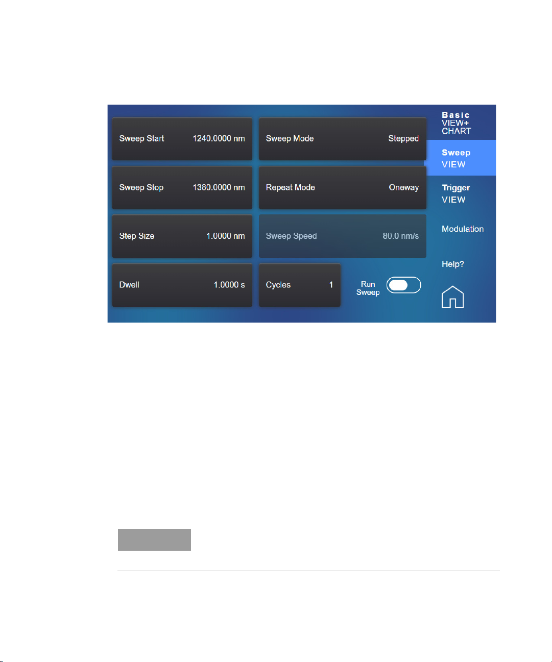
5 N777-C Instrument’s Front Panel Display
NOTE
These are the parameters for the wavelength sweep:
• Sweep Mode - see How to Perform a Sweep? on page 96,
• Repeat Mode - see How to Set the Repeat Mode? on page 95,
• Sweep Speed - the speed of a continuous sweep,
• Cycles - the number of times the sweep is repeated,
• Dwell - the amount of time spent at the wavelength during each step,
for a stepped sweep
• Sweep Start - the wavelength at which the sweep begins,
• Sweep Stop - the wavelength at which the sweep ends,
• Sweep Step - the size of the change in the wavelength for each step of
a sweep,
• Run/Stop Sweep - to run and start the sweep.
For a Continuous sweep, Step sets the wavelength interval between
output triggers, if you have set Output Trigger Mode to Step Finished,
How to Use Output Triggering on page 99.
see
94 Keysight N777-C Series Tunable Laser Family User’s Guide
Page 95

Figure 30 The Parameters for a Stepped Wavelength Sweep
How to Set the Repeat Mode?
The Repeat Mode determines how the instrument performs a multi-cycle
sweep.
• Select Two way, if you want to start every odd sweep cycle at [λ Start]
and to start each even sweep cycle at [λ Stop].
• Select Oneway, if you want to start every sweep cycle at [λ Start] and to
end every sweep cycle at [λ Stop].
N777-C Instrument’s Front Panel Display 5
Figure 31 illustrates how these modes work for a three-cycle wavelength
sweep.
Figure 31 Repeat Modes
Keysight N777-C Series Tunable Laser Family User’s Guide 95
Page 96

5 N777-C Instrument’s Front Panel Display
NOTE
How to Set the Maximum Power for the Sweep Range?
Pressing Set P
sweep range. Pressing Set P
constant for the whole sweep.
How to Perform a Sweep?
There are three sweep modes:
• Stepped - which dwells at wavelengths that are separated by a certain
step size,
• Continuous - which sweeps continually at the speed you set, and
• Manual - which you can run each step manually.
/Sweep sets the power to the maximum for the selected
max
/Sweep ensures the power will be
max
You cannot turn the laser off by pressing the Active hardkey on the
Tunable Laser front panel, while a wavelength sweep is running.
You can press Stop Sweep and, then, press the Active hardkey on the
Tunable Laser front panel, to turn off the laser.
96 Keysight N777-C Series Tunable Laser Family User’s Guide
Page 97
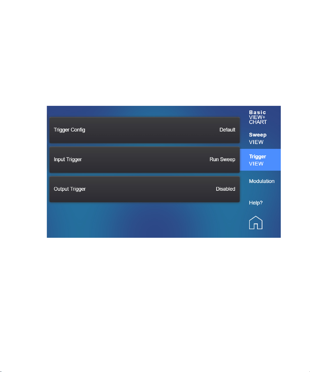
How to Use Triggers?
N777-C Instrument’s Front Panel Display 5
The N777-C Tunable Laser instruments allow you to trigger the instrument
to perform tasks and to output trigger signals to external measurement
instruments.
To view the Trigger window, click on the Trigger VIEW tab. The following
window appears:
How to Set the Trigger Configuration
The trigger level at the external trigger connectors is by default active
high, this means when a trigger rises above the high TTL level (rising
edge), a trigger is accepted.
You can use the Trigger Config drop-down menu to select the triggering
mode.
Keysight N777-C Series Tunable Laser Family User’s Guide 97
Page 98

5 N777-C Instrument’s Front Panel Display
CAUTION
How to Use Input Triggering
The following trigger configuration modes are available:
1 Disabled - select this mode if you do not want to use triggering. In this
case input and output connectors are disabled.
2 Default - select this mode if you want to enable the trigger connectors.
In this case input and output connectors are active.
3 Passthrough - select this mode if you want an input trigger to
automatically generate an output trigger. This allows you to trigger
another instrument almost simultaneously.
98 Keysight N777-C Series Tunable Laser Family User’s Guide
You can configure your N777-C Tunable Laser instrument to perform
certain tasks when you apply a trigger to the Input Trigger Connector.
A maximum of 5 V can be applied as an external voltage to the Input
Trigger connector.
Do not apply an external voltage to these connectors.
To set your instrument’s Input Trigger Configuration:
1From the Control Instrument window, click Trigger VIEW tab.
2 Use the menu to select the Input Trigger. The following input trigger
options are available:
• Ignore, input triggers are ignored.
• Next Step, an input trigger will cause the next step of a stepped
sweep to be performed.
• Run Sweep, an input trigger will start a single sweep cycle.
Page 99

3 You can generate input triggers in any of the following ways:
NOTE
• applying a trigger to the Input Trigger Connector on the rear panel
of your instrument,
• setting Trigger Configuration to Loopback so that an output trigger
automatically generates an input trigger, or
• using the :TRIGger1 command, see your N777-C Programming
Guide.
How to Use Output Triggering
You can configure your Tunable Laser instrument to output a trigger when
the instrument performs certain tasks.
To set your instrument’s Output Trigger Configuration:
1From the Control Instrument window, click Trigger VIEW tab.
2 Use the menu to select the Output Trigger. The following output
trigger options are available:
• Disabled, the output trigger mode is disabled.
• Step Finished, a trigger is output after every step of a sweep
finishes.
• Sweep Finished, a trigger is output after a sweep cycle finishes.
• Sweep Started, a trigger is output after a sweep cycle starts.
N777-C Instrument’s Front Panel Display 5
If you choose Step Finished and a Continuous sweep, the wavelength
interval between hardware triggers is set by the Step parameter,
although, the sweep is not stepped.
Keysight N777-C Series Tunable Laser Family User’s Guide 99
Page 100

5 N777-C Instrument’s Front Panel Display
How to set Modulation?
To view the Modulation window, click on the Modulation tab. The
following window appears:
The following modulation modes are available:
• OFF - No modulation
• Coherence - You can use coherence control to increase the line width
of the optical signal output from your Tunable Laser instrument.
Enabling the coherence control increases the line width of the optical
output signal to between 50 and 500 MHz (typically). Coherence
control greatly reduces interference effects and therefore improves the
power stability in sensitive test setups.
The N777-C instruments also allow adjustment of the line width
broadening with the "Coherence Level" setting. A level of 100%
corresponds to minimal broadening. The default level is usually a good
setting.
• Wavelength Locking - You can choose wavelength locking as the
modulation source, so the change in output wavelength is roughly
proportional to the voltage you apply to the input BNC connector on
the front panel of your Tunable Laser instrument.This enables you to
fine tune the output wavelength within a limited wavelength range.
100 Keysight N777-C Series Tunable Laser Family User’s Guide
 Loading...