

Page 1
User’s Guide
Keysight N774x Series
N7744A 4-Channel Optical Multiport Power Meter (LXI)
N7745A 8-Channel Optical Multiport Power Meter (LXI)
N7747A 2-Channel High Sensitivity Optical Power Meter
N7748A 4-Channel High Sensitivity Optical Power Meter
Page 2

Page 3

Notices
THE MATERIAL CONTAINED IN THIS
DOCUMENT IS PROVIDED “AS IS,”
AND IS SUBJECT TO BEING
CHANGED, WITHOUT NOTICE, IN
FUTURE EDITIONS. FURTHER, TO
THE MAXIMUM EXTENT PERMITTED
BY APPLICABLE LAW, KEYSIGHT
DISCLAIMS ALL WARRANTIES,
EITHER EXPRESS OR IMPLIED, WITH
REGARD TO THIS MANUAL AND ANY
INFORMATION CONTAINED HEREIN,
INCLUDING BUT NOT LIMITED TO
THE IMPLIED WARRANTIES OF
MERCHANTABILITY AND FITNESS
FOR A PARTICULAR PURPOSE.
KEYSIGHT SHALL NOT BE LIABLE
FOR ERRORS OR FOR INCIDENTAL
OR CONSEQUENTIAL DAMAGES IN
CONNECTION WITH THE
FURNISHING, USE, OR
PERFORMANCE OF THIS DOCUMENT
OR OF ANY INFORMATION
CONTAINED HEREIN. SHOULD
KEYSIGHT AND THE USER HAVE A
SEPARATE WRITTEN AGREEMENT
WITH WARRANTY TERMS COVERING
THE MATERIAL IN THIS DOCUMENT
THAT CONFLICT WITH THESE
TERMS, THE WARRANTY TERMS IN
THE SEPARATE AGREEMENT SHALL
CONTROL.
CAUTION
CAUTION
A WARNING notice denotes a
hazard. It calls attention to an
operating procedure, practice,
or the like that, if not correctly
performed or adhered to, could
result in personal injury or
death. Do not proceed beyond a
WARNING notice until the
indicated conditions are fully
understood and met.
CAUTION
© Keysight Technologies, Inc. 2017
No part of this manual may be
reproduced in any form or by any
means (including electronic storage
and retrieval or translation into a
foreign language) without prior
agreement and written consent from
Keysight Technologies, Inc. as
governed by United States and
international copyright laws.
Manual Part Number
N7744-90B01
Edition
Edition 7.0, October 2017
Keysight Technologies,
Deutschland GmbH
Herrenberger Str. 130
71034 Böblingen, Germany
For Assistance and Support
http://www.keysight.com/find/assist
Limitation of Warranty
The foregoing warranty shall not
apply to defects resulting from
improper or inadequate maintenance
by Buyer, Buyer-supplied software or
interfacing, unauthorized modification
or misuse, operation outside of the
environmental specifications for the
product, or improper site preparation
or maintenance. No other warranty is
expressed or implied. Keysight
Technologies specifically disclaims
the implied warranties of
Merchantability and Fitness for a
Particular Purpose.
Warranty
Technology Licenses
The hardware and/or software
described in this document are
furnished under a license and may be
used or copied only in accordance
with the terms of such license.
Restricted Rights Legend
If software is for use in the
performance of a U.S. Government
prime contract or subcontract,
Software is delivered and licensed as
“Commercial computer software” as
defined in DFAR 252.227-7014 (June
1995), or as a “commercial item” as
defined in FAR 2.101(a) or as
“Restricted computer software” as
defined in FAR 52.227-19 (June 1987)
or any equivalent agency regulation
or contract clause. Use, duplication or
disclosure of Software is subject to
Keysight Technologies’ standard
commercial license terms, and nonDOD Departments and Agencies of
the U.S. Government will receive no
greater than Restricted Rights as
defined in FAR 52.227-19(c)(1-2)
(June 1987). U.S. Government users
will receive no greater than Limited
Rights as defined in FAR 52.227-14
(June 1987) or DFAR 252.227-7015
(b)(2) (November 1995), as applicable
in any technical data.
Safety Notices
A
hazard. It calls attention to an
operating procedure, practice,
or the like that, if not correctly
performed or adhered to, could
result in damage to the product
or loss of important data. Do not
proceed beyond a
notice until the indicated
conditions are fully understood
and met.
WARNING
notice denotes a
Page 4

Contents
1 Getting Started
Overview 7
Keysight N7744A and N7745A Optical Power Meter 8
Keysight N7747A and N7748A Optical Power Meter 8
Initial Inspection 9
Safety Considerations 9
Safety Considerations - Overview 9
Safety Symbols 10
General 11
Operating Environment 11
Line Power Requirements 11
Input/Output Signals 12
Line Power Connectors 12
Instrument Markings 13
AC Line Power Supply Requirements 13
AC Line Power Supply Requirements - Overview 13
Line Power Requirements 14
Line Power Cable 14
Changing the Fuse 15
Operating and Storage Environment 16
Operating and Storage Environment - Overview 16
Temperature 16
Humidity 16
Altitude 16
Pollution Protection 16
Instrument Cooling 17
Input and Output Connectors 18
Input and Output Connectors - Overview 18
Front Panels - Multiport Power Meters 18
Rear Panel 19
Keysight N774x Series 3
Page 5

Making Optical Connections 20
Making Optical Connections 20
Making Quad-adapter Connections on the Keysight N7744/45A Multiport
Power Meter 21
Electrical Connectors 22
LAN Interface 23
LAN Interface 23
Selecting a LAN Network 23
Private LAN Considerations 23
Security 24
Performance 24
Reliability 24
IP Address Availability 24
Site LAN Considerations 25
Connecting the LAN Cable 25
GPIB Interface 27
GPIB Interface 27
Cables and Adapters 27
Connector 28
GPIB Logic Levels 28
USB Interface 29
Powering Up the Instrument 29
Powering Up the Instrument 29
Front Panel Indicators 30
Connecting to the Instrument 30
Connecting to the Instrument - Overview 30
Connecting over USB 30
Finding the IP Address of an instrument 32
Connecting over LAN 33
Claims and Repackaging 37
Claims and Repackaging - Overview 37
Return Shipments to Keysight Technologies
N77xx Viewer Common User Interface Functions 38
Connecting to an Instrument 38
Viewing Measurements and Settings 40
Saving and Recalling Configurations 41
Controlling the Instrument Refresh 42
2 Power Measurement
Power Measurement 43
37
4 Keysight N774x Series
Page 6

Controlling the Optical Multiport Power Meter 43
How to Measure Power 47
The Power Value 47
How to Set the Power Unit 48
How to Set the Calibration Offset 49
How to Set the Reference Level 49
How to Set the Wavelength 51
How to Remove Electrical Offsets (Zero) 51
How to Choose the Range Mode 53
How to Set the Range 53
How to Set the Averaging Time 54
How to Set Automatic Gain for Averaging Modulated Signals 54
How to Choose the MinMax Mode 55
How to Use External Triggers 56
3 Power Meter Applications
Power Meter Applications 59
The Logging Application 59
Continuous Logging Using Data Buffers 60
The Stability Application 61
4 Specifications and Regulations Compliance
Definition of Terms 63
Literature 71
Technical Specifications - Keysight N7744A and N7745A 72
Technical Specifications - Keysight N7747A and N7748A 74
Declaration of Conformity - Keysight N7744A and N7745A 75
Declaration of Conformity - Keysight N7747A and N7748A 76
Regulations Information 77
EMC Canada 78
Acoustic Noise Information Germany 78
Certification 78
Certification 78
Keysight N774x Series 5
Page 7

Remove All Doubt 79
Remove All Doubt 79
Keysight E-mail Updates 79
Keysight Direct 79
Keysight Open 80
LXI 80
www.keysight.com 80
5 Accessories
Accessories - Overview 81
Instrument and Options - Keysight N7744A and N7745A 81
Instrument and Options - Keysight N7747A and N7748A 83
Cables 84
6 Maintenance and Troubleshooting
Maintenance and Troubleshooting - Overview 85
Cleaning Instructions 85
Cleaning Instructions 85
Cleaning Instructions for this Instrument 86
Safety Precautions 86
Why is it important to clean optical devices? 86
What do I need for proper cleaning? 87
Preserving Connectors 92
Cleaning Instrument Housings 92
Which Cleaning Procedure should I use? 93
How to clean connectors 93
How to clean connector adapters 95
How to clean bare fiber adapters 95
How to clean optical glass plates 96
Additional Cleaning Information 96
Other Cleaning Hints 97
Firmware Upgrades 97
Error Messages 98
SYST:ERR? 98
Hardware Error 98
Data Sanitation 98
Memory Inventory 98
Clearing User Data 99
Index 101
6 Keysight N774x Series
Page 8

Overview
Keysight N774x Series
User's Guide
1 Getting Started
This chapter helps you start using your N77-Series instrument.
“Keysight N7744A and N7745A Optical Power Meter” on page 8
•
“Keysight N7747A and N7748A Optical Power Meter” on page 8
•
“Initial Inspection” on page 9
•
“Safety Considerations - Overview” on page 9
•
“AC Line Power Supply Requirements - Overview ” on page 13
•
“Operating and Storage Environment - Overview ” on page 16
•
“Input and Output Connectors - Overview” on page 18
•
“Making Optical Connections” on page 20
•
“Electrical Connectors” on page 22
•
“LAN Interface” on page 23
•
“GPIB Interface” on page 27
•
“USB Interface” on page 29
•
“Powering Up the Instrument” on page 29
•
“Connecting to the Instrument - Overview” on page 30
•
“Claims and Repackaging - Overview” on page 37
•
7
Page 9

1 Getting Started
Keysight N7744A and N7745A Optical Power Meter
The Keysight N7744A and Keysight N7745A are LXI compliant optical
power meters with 4 or 8 power-sensor ports respectively. They address
productivity challenges by increasing throughput and operational
efficiency using industry-leading device connectivity, high-speed
acquisition of measurement data and fast data transfer for postprocessing.
The Keysight N7744A and Keysight N7745A are designed to
characterize optical multiport components, such as multiplexers, PON
splitters, wavelength selective switches (WSS) and ROADMs, in all
product phases from R&D to manufacturing.
The one rack unit (1U half-rack high) instrument can be operated alone
or with other units, by PC connected over LAN, USB, or GPIB.
The unprecedented N7740A fiber connectivity concept consists of a
quadruple adapter (quad-adapter) with a quick-locking mechanism. Up
to four fiber connectors from the device under test (DUT) can be
connected in a comfortable working position to one quad-adapter. The
push-on locking mechanism makes it easy and secure to attach the quadadapter to and remove the quad-adapter from the instrument in
seconds. With multiple quad-adapters, the measurement task can be
fully separated from the DUT connection task. This means a further
increase in test throughput. Where this is not an issue, traditional single
connector connectivity is supported as well.
These power meters are highly compatible with setups and programs
developed using the Keysight 816x modular power meters. They are
also easy to synchronize with Keysight tunable laser sources, to make
spectral measurements. The functionality for time-dependent
measurement has been extended with sampling at up to 1 MHz and
data logging of up to 1 million samples for each port.
Keysight N7747A and N7748A Optical Power Meter
The two-port N7747A and 4-port N7748A optical power meters bring
the highest performance in terms of sensitivity, noise and relative
accuracy to the compact N77 instrument platform. These instruments
combine the optical performance of the 81634B sensor modules with
the large memory, fast data transfer and small footprint of the N77
series platform. Eight high-sensitivity optical power meters now fit in
a single rack unit. Optical connections are made with the
interchangeable 81000xI connector interface system.
8 Keysight N774x Series
Page 10

Initial Inspection
Getting Started 1
Inspect the shipping container for damage. If there is damage to the
container or cushioning, keep them until you have checked the contents
of the shipment for completeness and verified the instrument both
mechanically and electrically. The Function Tests give a procedure for
checking the operation of the instrument. If the contents are incomplete,
mechanical damage or defect is apparent, or if an instrument does not
pass the operator’s checks, notify the nearest Keysight Technologies
Sales/Service Office.
N O T E
Safety Considerations
Safety Considerations - Overview
To avoid hazardous electrical shock, do not perform electrical tests when there are
signs of shipping damage to any portion of the outer enclosure (covers, panels, and
so on).
The following generalsafety precautions must be observed during all
phases of operation, service, and repair of this instrument. Failure to
comply with these precautions or with specific warnings elsewhere in
this manual violates safety standards of design, manufacture, and
intended use of the instrument. Keysight Technologies Inc. assumes no
liability for the customer’s failure to comply with these requirements.
This product has been designed and tested in accordance with IEC
Publication 61010-1, Safety Requirements for Electrical Equipment for
Measurement, Control and Laboratory, and has been supplied in a safe
condition. The instruction documentation contains information and
warnings that must be followed by the user to ensure safe operation and
to maintain the product in a safe condition.
Keysight N774x Series 9
Page 11

1 Getting Started
Safety Symbols
C A U T I O N
W A R N I N G
The caution sign denotes a hazard. It calls attention to a procedure which, if not
correctly performed or adhered to, could result in damage to or destruction of the
product. Do not proceed beyond a caution sign until the indicated conditions are
fully understood and met.
The warning sign denotes a hazard. It calls attention to a procedure which, if not
correctly performed or adhered to, could result in injury or loss of life. Do not
proceed beyond a warning sign until the indicated conditions are fully understood
and met.
10
Keysight N774x Series
Page 12
General
Getting Started 1
This is a Safety Class 1 instrument (provided with a protective earth
terminal) and has been manufactured and tested according to
international safety standards.
Before operation, you should review the instrument and manual for
safety markings and instructions. You must follow these to ensure safe
operation and to maintain the instrument in safe condition.
Some circuits are powered whenever the instrument is connected to the
AC power source. To disconnect from the line power, disconnect the
power cord either at the rear power inlet or at the AC line power source
(receptacle). One of these must always be accessible. If the instrument
is in a cabinet, it must be disconnected from the line power by the
system’s line power switch.
W A R N I N G
To avoid hazardous electrical shock, do not perform electrical tests when there
are signs of shipping damage to any portion of the outer enclosure (covers,
panels, and so on).
Operating Environment
W A R N I N G
The instrument is not designed for outdoor use. To prevent potential fire or shock
hazard, do not expose the instrument to rain or other excessive moisture.
Line Power Requirements
C A U T I O N
The instrument complies with installation category II and can operate from the
single-phase AC power source that supplies between 100 V and 240 V at a frequency
in the range 50 to 60 Hz. The maximum voltage fluctuation is 10% of the nominal
supply voltage. The maximum power consumption is 60 VA with all options installed.
Keysight N774x Series 11
Page 13

1 Getting Started
Input/Output Signals
C A U T I O N
There is one input BNC connector: Trigger In. This is a TTL input.
A maximum of 5 V can be applied as an external voltage to this input connector.
There is one output BNC connector: Trigger Out. This is a TTL output. Do not apply
an external voltage to this connector.
The N7747A and N7748A have front-panel BNC connectors for each optical port.
This is an analog voltage output (0 to 2V). Do not apply an external voltage to this
connector.
Line Power Connectors
In accordance with international safety standards, the instrument has
a three-wire power cable. When connected to an appropriate AC power
receptacle, this cable earths the instrument cabinet. The type of power
cable shipped with each instrument depends on the country of
destination. Please refer to "Accessories" section in the User's Guide for
the part numbers of available power cables.
W A R N I N G
To avoid the possibility of injury or death, you must observe the following
precautions before switching on the instrument.
12
Insert the power cable plug only into a socket outlet provided with a protective
•
earth contact. Do not negate this protective action by the using an extension
cord without a protective conductor.
Do not interrupt the protective earth connection intentionally.
•
Do not remove protective covers. Operating personnel must not remove
•
instrument covers. Component replacement and internal adjustments must
be made only by qualified service personnel.
Instruments that appear damaged or defective should be made inoperative
•
and secured against unintended operation until they can be repaired by
qualified service personnel.
Defective, damaged, or malfunctioning laser sources must be returned to an
•
Keysight Technologies Service Center.
Do not operate the instrument in the presence of flammable gases or fumes.
Operation of any electrical instrument in such an environment constitutes a
definite safety hazard.
Keysight N774x Series
Page 14
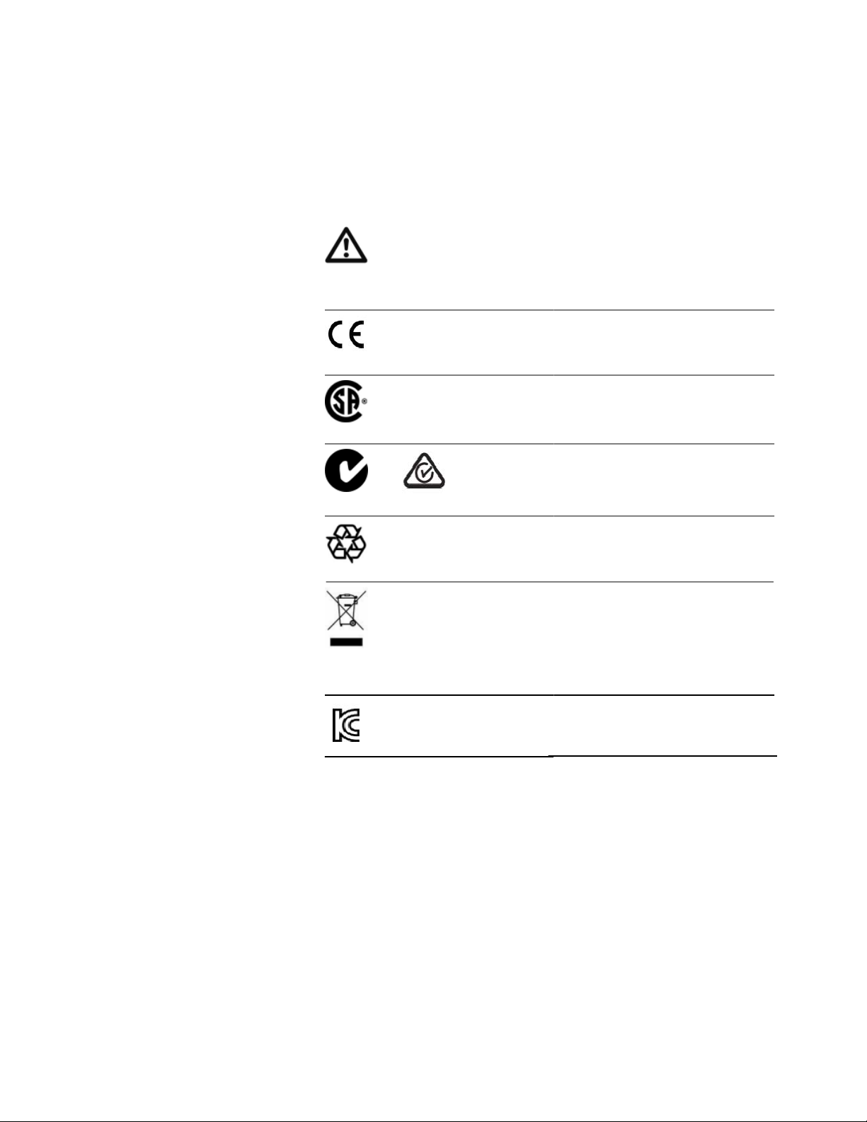
Instrument Markings
Getting Started 1
The instruction manual symbol. The
product is marked with this warning
symbol when it is necessary for the user
to refer to the instructions in the manual.
The CE mark is the conformity marking
of the European Community
The CSA mark is a registered trademark
of the Canadian Standards Association.
or
AC Line Power Supply Requirements
AC Line Power Supply Requirements - Overview
The C-Tick or RCM mark is the
certification mark of the Australian
Communications Authority.
The recycling symbol indicates the
general ease with which the instrument
can be recycled.
Do not dispose in domestic household
waste. To return unwanted products,
contact your local Keysight office, or
see
http://about.keysight.com/en/
companyinfo/environment/
takeback.shtml for more information.
The KC mark is the Korean certification
mark.
This secton provides information on:
Line Power Requirements
•
Line Power Cable
•
Keysight N774x Series 13
Page 15
1 Getting Started
Changing the Fuse
•
Line Power Requirements
The instrument complies with installation category II and can operate
from the single-phase AC power source that supplies between 100 V and
240 V at a frequency in the range 50 to 60 Hz. The maximum voltage
fluctuation is 10% of the nominal supply voltage. The maximum power
consumption is 60 VA with all options installed.
Line Power Cable
In accordance with international safety standards, the instrument has
a three-wire power cable. When connected to an appropriate AC power
receptacle, this cable earths the instrument cabinet. For the part
number of the power cable for your country and instrument, see
“Accessories - Overview” on page 81.
C A U T I O N
Please note that the switch on the front panel of the instrument does not stop the
flow of power to the instrument.
If you need to turn off the power, unplug the instrument at the mains or remove the
power cable connector from the appliance coupler at the rear of the instrument. For
this reason, the power cable connection should be easily accessible - allowing you
to turn off the power quickly. If the instrument is in a cabinet, it must be disconnected
from the line power by the system’s line power switch.
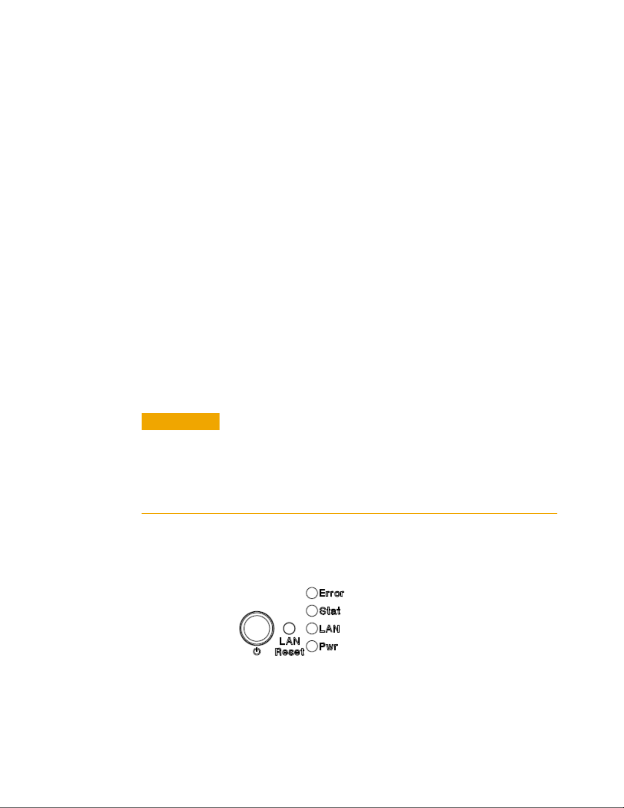
The power switch allows you to switch between stand-by mode and
power-on mode.
Figure 1 Power Switch
14
Keysight N774x Series
Page 16
Getting Started 1
When the instrument is in stand-by mode, the Pwr LED is orange. When
the instrument is powered-on, the Pwr LED is green.
W A R N I N G
To avoid the possibility of injury or death, you must observe the following
precautions before switching on the instrument.
Insert the power cable plug only into a socket outlet provided with a protective
•
earth contact. Do not negate this protective action by using an extension cord
without a protective conductor.
Do not interrupt the protective earth connection intentionally.
•
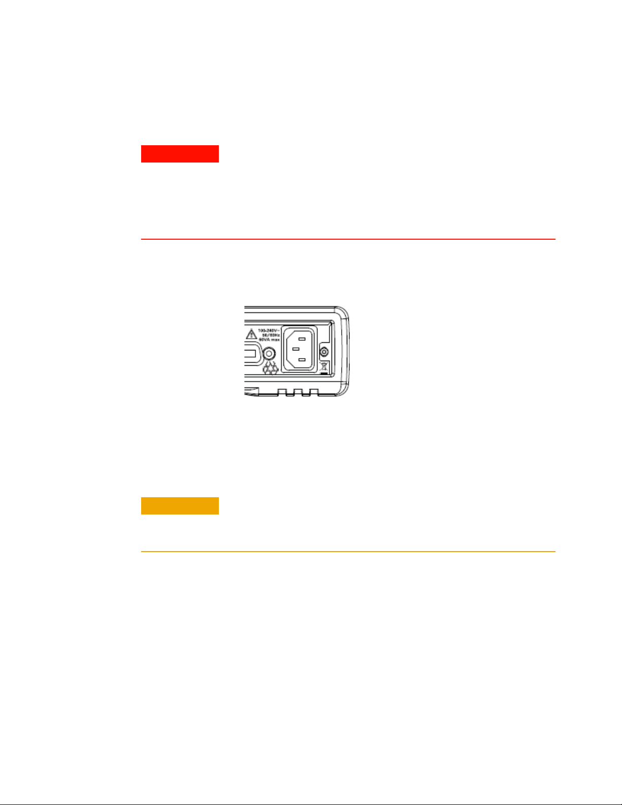
The AC power requirements are summarized on the rear panel of the
instrument.
Figure 2 AC Power Requirement Markings
Changing the Fuse
C A U T I O N
Keysight N774x Series 15
There is no user replaceable fuse for the instrument. Changing the fuse should be
carried out only by Keysight
the fuse replaced refer to your nearest Keysight Technologies Sales/Service
Office.
Technologies service personnel. If you need to get
Page 17

1 Getting Started
Operating and Storage Environment
Operating and Storage Environment - Overview
The following summarizes the operating environment ranges. In order
for the instrument to meet specifications, the operating environment
must be within these limits.
W A R N I N G
Temperature
Humidity
Altitude
The instrument is not designed for outdoor use. To prevent potential fire or shock
hazard, do not expose the instrument to rain or other excessive moisture.
The instrument should be protected from temperature extremes and
changes in temperature that may cause condensation within it.
The operating temperature is from 5°C to +40°C.
The storage temperature is from -40°C to +70°C.
The operating humidity is 15 to 95%, non-condensing.
16
The maximum operating altitude is 2000 m.
Pollution Protection
The instruments are designed for pollution degree 2.
Keysight N774x Series
Page 18
Instrument Cooling
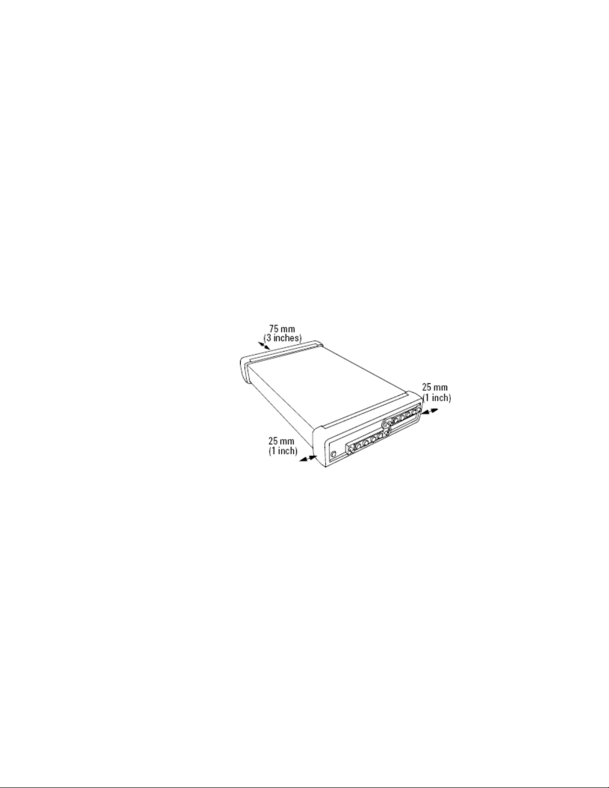
The instrument has a cooling fan mounted internally.
Mount or position your instrument upright and horizontally, as shown
in Figure 4 so that air can circulate through it freely.
Operating Position
When operating the instrument choose a location that provides at least
75 mm (3 inches) of clearance at the rear, and at least 25 mm (1 inch)
of clearance at each side. Failure to provide adequate air clearance may
result in excessive internal temperature, reducing instrument
reliability. The instrument should not be operated when resting on its
rear or side panels.
Getting Started 1
Figure 3 Correct Operating Position
(shown here for the Keysight N7744/5A, valid also for the
N7747/48A, N7751/2A, Keysight
and the N7711/4A)
Keysight N774x Series 17
N7761/2/4A, N7766/68A, N773xA
Page 19
1 Getting Started
Input and Output Connectors
Input and Output Connectors - Overview
This section provides information on:
•
•
Front Panels - Multiport Power Meters
Front Panels - Multiport Power Meters
Rear Panel
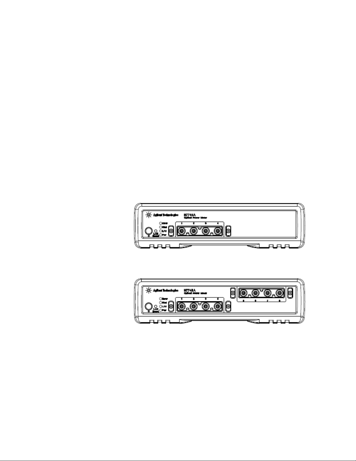
Figure 4 Front panel of the Keysight N7744A 4-Channel Optical Multiport
Power Meter
Figure 5 Front panel of the Keysight N7745A 8-Channel Optical Multiport
Meter
Power
18
Keysight N774x Series
Page 20
Getting Started 1
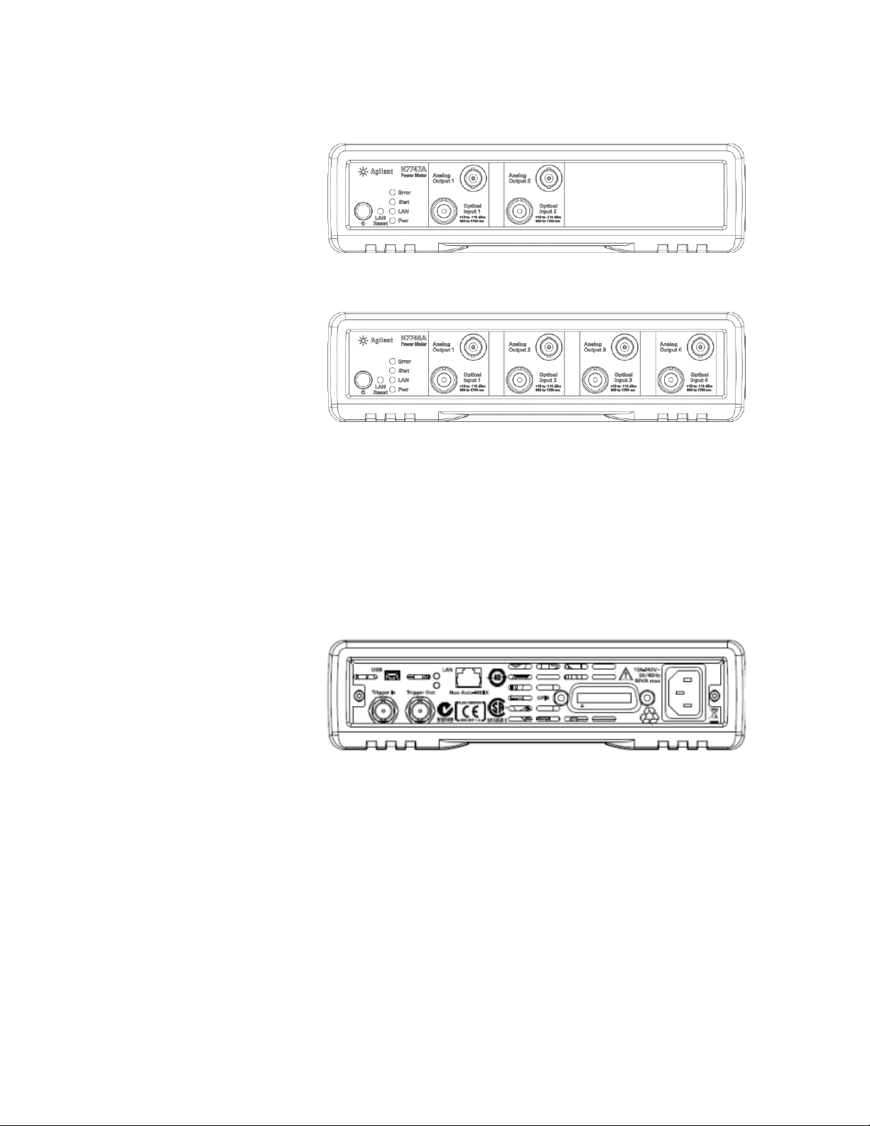
Figure 6 Front panel of the Keysight N7747A 2-Channel Optical Power Meter
Figure 7 Front panel of the Keysight N7748A 4-Channel Optical Power Meter
Rear Panel
Figure 8 Rear panel of the Keysight N77xx Series instruments
Keysight N774x Series 19
Page 21
1 Getting Started
Making Optical Connections
Making Optical Connections
The N774xA power meters do not make contact to the fiber connector
faces and can be used with either angled or straight connectors. The
N7744A and N7745A use the quad-adapters described below. The
N7747A and N7748A use the interchangeable 81000xI connector
interfaces, selected for the desire connector type. Common choices are
the 81000FI for FC connectors, 81000KI for SC connectors, and 81002LI
for LC connectors. The 81000BI can be used for bare fiber connections.
C A U T I O N
N O T E
When using bare fiber connections to power meters, the length of fiber extending
from the fiber holder must be carefully adjusted to avoid scratching the power meter
optics.
Connector ferrules with conical or raised-end faces also add positioning uncertainty
and are not recommended for use with the N7747A or N7748A.
For further details on connector interfaces and accessories, refer to the
"Accessories" section in the User's Guide.
20
Keysight N774x Series
Page 22
Getting Started 1
Making Quad-adapter Connections on the Keysight N7744/45A Multiport Power Meter
N O T E
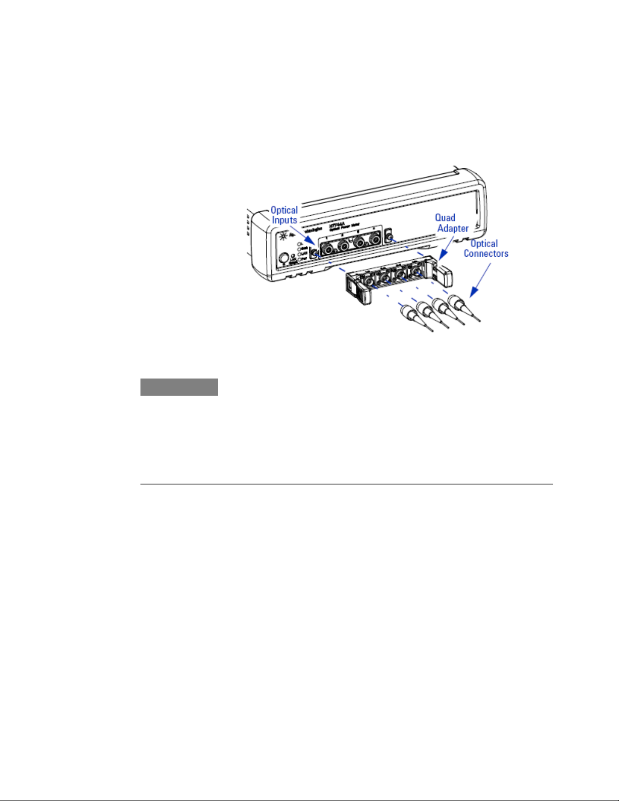
Figure 9 Connecting Optical Fibers
Before you attach a quad-adapter or fiber, you should make sure they are clean.
This is important for accurate measurements.
The fibers do not contact the optical inputs (all contact with the optical inputs should
be avoided). Usually the only cleaning necessary for the optical inputs is the gentle
removal of dust with pressurized, dry air.
For further information, refer to "Maintenance and Troubleshooting" section,
described in this manual.
To use a quad-adapter to connect optical fibers to the power meter
inputs:
Select the quad-adapter that suits the optical connector that your
1
optical fiber is terminated with.
Attach the optical connectors to the quad-adapter. You can attach
2
up to 4 fibers to the quad-adapter at the same time.
Make sure the number labels on the quad-adapter are at the top.
3
Connect the quad-adapter to the optical inputs by pressing it on until
4
it clicks securely into place, without pressing the release levers.
Keysight N774x Series 21
Page 23
1 Getting Started
Removing Quad-adapter Interfaces from the Keysight
N7744/5A Multiport Power Meter
N O T E
N O T E
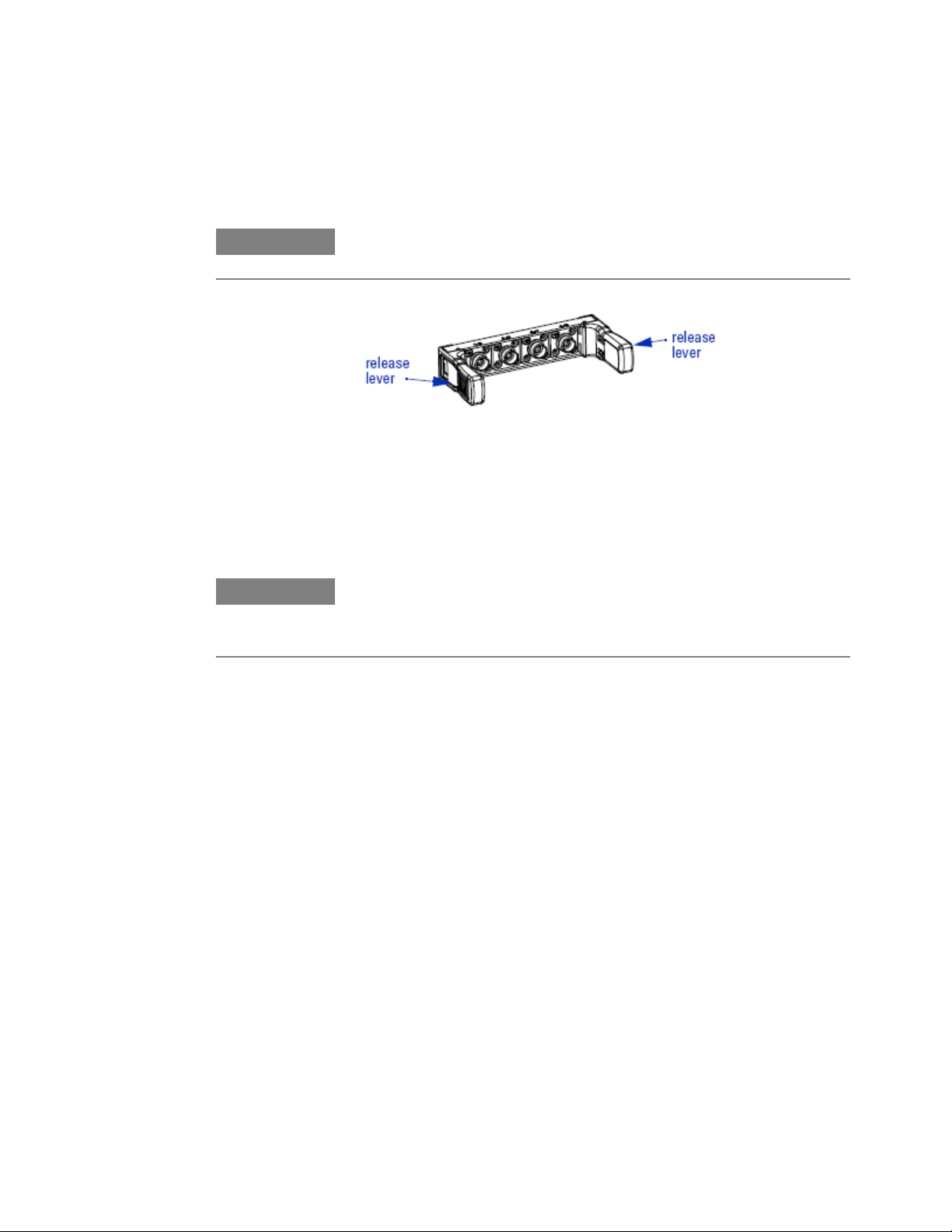
There are release levers on both sides of the quad-adapter for removing it from the
optical inputs.
Figure 10 Removing Quad-adapter Interfaces
Press the release levers on both sides of the quad-adapter to release
1
it from the front panel of the power meter.
You can now remove the optical connectors from the quad-adapter.
2
Always place the dust cap on unused connector interfaces.
You can use the quad-adapter dust caps to protect the four power meter inputs and
the rear of the quad-adapter, for example, when fibers are attached.
Electrical Connectors
22
There are two BNC connectors on the rear panel of your instrument.
These are the Trigger Out and the Trigger In connectors.
The N7747A and N7748A have a front panel BNC connector for each
channel. These are for analog output signals and provide a voltage
proportional to the input signal power in mW. The voltage is in the range
0-2 V and 1 V corresponds to the value of the currently selected power
range. For example, when using the -10 dBm range, a 100 µW optical
power will give 1 V analog output.
Keysight N774x Series
Page 24

Getting Started 1
LAN Interface
LAN Interface
Selecting a LAN Network
C A U T I O N
The Trigger In is a TTL input. A maximum of 5 V can be applied as an external voltage
to this input connector.
The Trigger Output is a TTL output. Do not apply an external voltage to this
connector.
No external voltage should be applied to the analog output connectors of the
N7747A and N7748A.
This section explains the concept of LAN in details.
For the purposes of this guide, a private (isolated) LAN network is
defined as a network configuration in which instrument access is a
direct connection between the computer and the instrument, or to
multiple instruments connected via a dedicated router or switch. A site
(company-wide) LAN is defined as a network in which instrument
access is available to many users at on-site and remote locations. The
instrument’s application and/or your company’s IT (Information
Technology) department may have guidelines that help decide the type
of network (private or site) used. If a network configuration has not
been determined, refer to the following considerations concerning each
type.
Private LAN Considerations
Among the basic parameters of a private LAN network to consider are
security, performance, reliability, and IP address availability.
Keysight N774x Series 23
Page 25

1 Getting Started
Security
A private network generally involves a direct connection between the
computer and the instrument, or to multiple instruments using switches
or routers. Access to the instrument is limited to users on the private
network, as opposed to users on a site network that could locate and
access the instrument from any location.
Private networks can reduce the possibility of tests being disrupted by
unplanned or unauthorized access. Code generation for test systems on
a private network is often simplified, as provisions against
unauthorized users may not be required.
Performance
Test systems where large amounts of data are transferred usually have
faster throughput on a private network. On a site network, heavy and
unpredictable LAN traffic affects each instrument (node) on the
network. The impact on a test system is that repeatability is difficult to
achieve as latencies are difficult to account for.
Reliability
Private networks are fundamentally more reliable than site networks
as they host fewer users and are less complex than site networks.
Private networks are isolated from conditions that could bring down
(crash) a site network.
IP Address Availability
Every instrument (node) on a LAN (private or site) has an IP (Internet
Protocol) address. Due to the expanding use of the internet, the number
of site network IP addresses available is limited. By using a router with
Dynamic Host Configuration Protocol (DHCP) capability on a private
network, the router can assign an IP address to each instrument thus
creating a sub-network (subnet) that does not consume site IP
addresses.
24 Keysight N774x Series
Page 26
Site LAN Considerations
For applications requiring access by many users or by users at
distributed sites, a site LAN network is required. In addition to
supporting multiple users, site LANs often offer the advantage of being
maintained by IT departments. When using a site LAN, consult your IT
department regarding LAN configuration and security issues.
Connecting the LAN Cable
LAN cables are connected between the LAN terminal on the instrument
and the computer, or between the instrument and a router or switch if
included in your network.
Private Network Connections
Getting Started 1
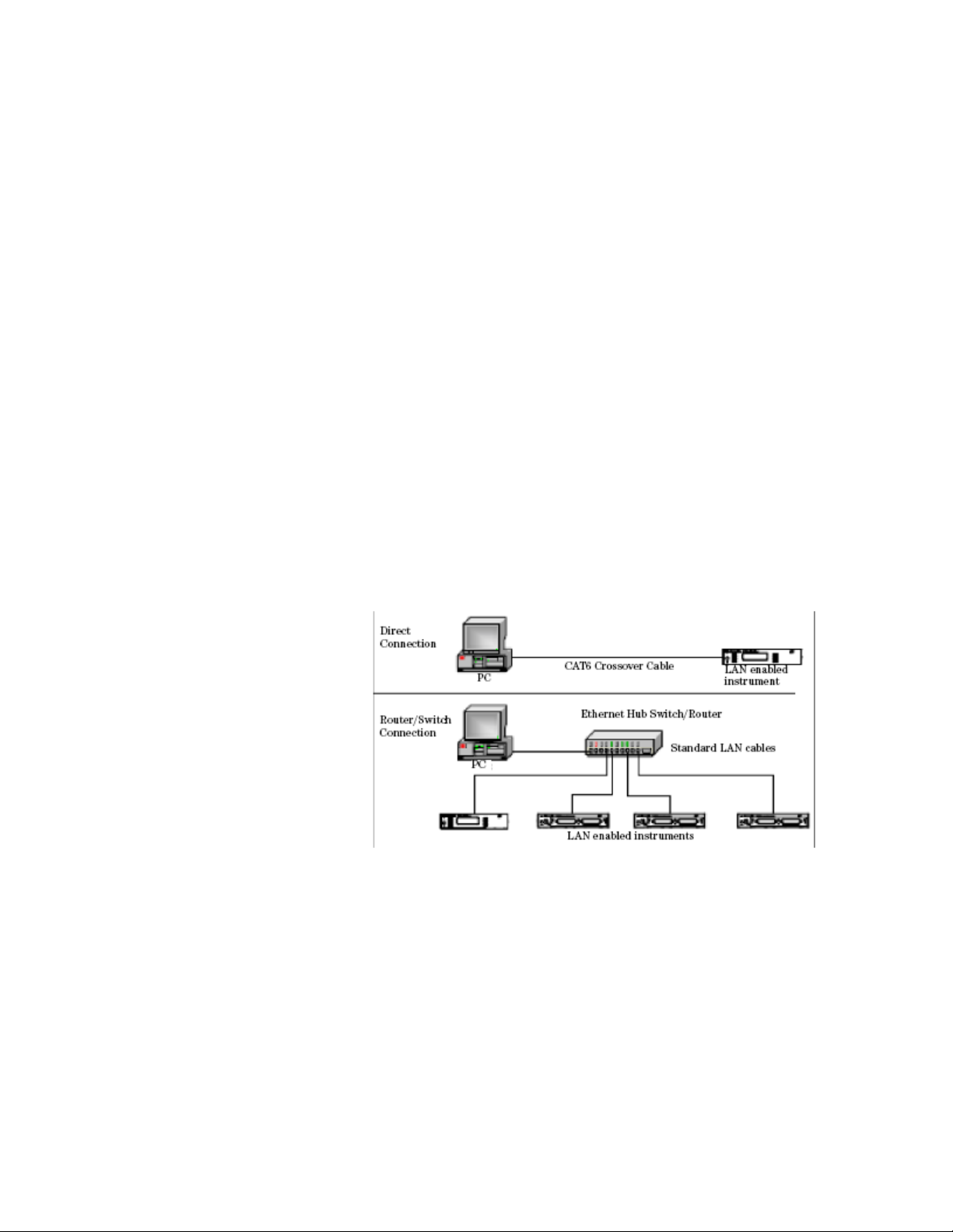
The figure below shows typical LAN cable connections for a private
network.
Figure 11 Typical Private (isolated) LAN Network Connections
If the instrument is connected directly to the PC, use a LAN crossover
cable, as provided with the instrument. If your computer supports AutoMDIX or contains a LAN card with gigabit data transfer rates, the (blue)
crossover cable is not required. A standard LAN cable can be used
instead.
For private LAN networks that include a switch or router, use standard
LAN cables for all network connections. Do not use a crossover cable.
Keysight N774x Series 25
Page 27
1 Getting Started
Site Network Connections
The following figure shows a typical LAN cable connection for a site
network.
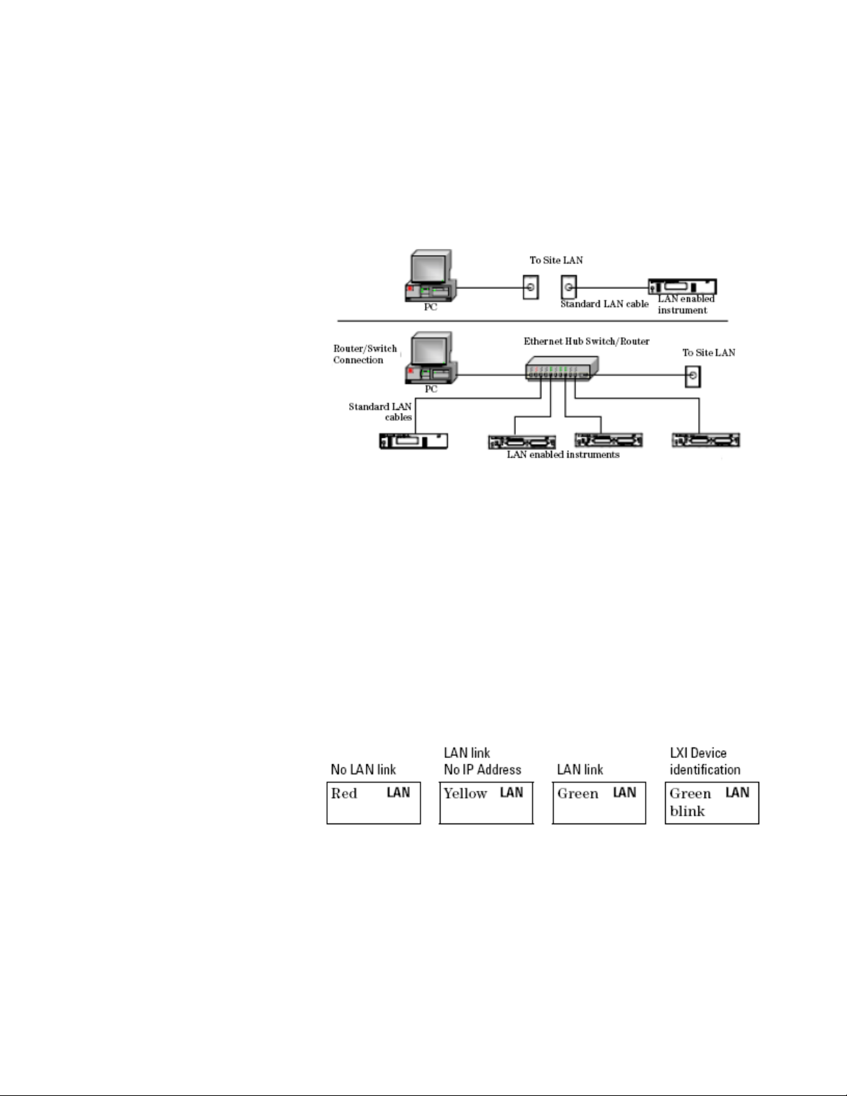
Figure 12 Typical Site LAN Network Connections.
On site networks, the instrument and the computer are connected
directly to site LAN ports, or are connected to the site LAN through a
switch. In each site network configuration, standard LAN cables are
used.
The LAN LED
As the LAN connection is made, the DHCP server assigns an address
and the LXI device identification proceeds you will see the following
indicators:
Figure 13 The LAN LED
26
There may be a delay between making the LAN link (yellow status) and
getting the IP address (green status). This delay may be longer if there
Keysight N774x Series
Page 28

Getting Started 1
is no DHCP server, for example when the instrument is connected
directly to a PC.
The LAN Reset button
This recessed button has two functions.
Pressing the button briefly invokes a preset of the instrument and
•
restores default measurement settings. This is equivalent to the
programming command
:SYSTem:PRESet
Pressing and holding the button for 3 seconds will reset the LAN
•
parameters to the factory default. This includes changing the
password for modifying the configuration via LAN back to the
default "Keysight". This is equivalent to the following sequence of
programming commands:
:SYSTem:COMMunicate:ETHernet:RESet
GPIB Interface
GPIB Interface
Cables and Adapters
You can connect your GPIB interface into a star network, a linear
network, or a combination star and linear network. The limitations
imposed on this network are as follows:
The total cable length cannot exceed 20 meters.
•
The maximum cable length between devices is 4 meters, with an
•
average separation of 2m between devices over the whole bus.
No more than 15 devices may be interconnected on one bus.
•
For further details on cables and adapters, refer to "Cables" section in
the User's Guide.
Keysight N774x Series 27
Page 29
1 Getting Started
Connector
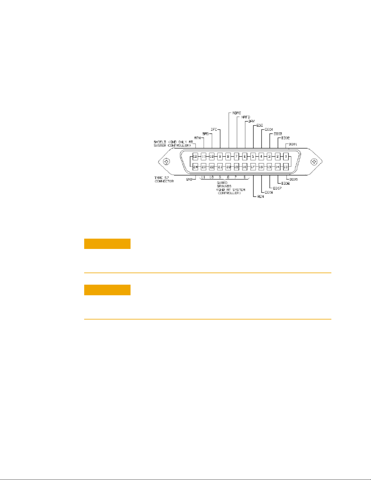
The following figure shows the connector and pin assignments.
Connector Part Number: 1251-0293
Figure 14 GPIB Connector
C A U T I O N
C A U T I O N
Keysight Technologies products delivered now are equipped with connectors
having ISO metric-threaded lock screws and stud mounts (ISO M3.5×0.6) that are
black in color. Earlier connectors may have lock screws and stud mounts with
English-threaded lock screws and stud mounts (6-32 UNC) that have a shiny
nickel finish.
It is recommended that you do not stack more than three connectors, one on top of
the other.
Hand-tighten the connector lock screws. Do not use a screwdriver.
GPIB Logic Levels
The instrument’s GPIB lines use standard TTL logic, as follows:
True = Low = digital ground or 0 Vdc to 0.4 Vdc
False = High = open or 2.5 Vdc to 5 Vdc
28
All GPIB lines have LOW assertion states. High states are held at 3.0 Vdc
by pull-ups within the instrument. When a line functions as an input, it
requires approximately 3.2 mA to pull it low through a closure to digital
Keysight N774x Series
Page 30
Getting Started 1
ground. When a line functions as an output, it will sink up to 48 mA in
the low state and approximately 0.6 mA in the high state.
N O T E
The GPIB line screens are not isolated from ground.
USB Interface
N O T E
Before connecting the instrument over USB, install the Keysight I/O Libraries
Suite, which is included on a CD with the instrument.
The instrument is a USB device, with a mini-USB connector.
Powering Up the Instrument
Powering Up the Instrument
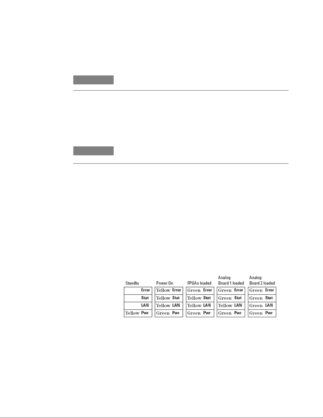
When you switch on the instrument, the LEDs on the front panel show
the various stages of booting.
Figure 15 Powering Up the Instrument
Keysight N774x Series 29
Page 31
1 Getting Started
Front Panel Indicators
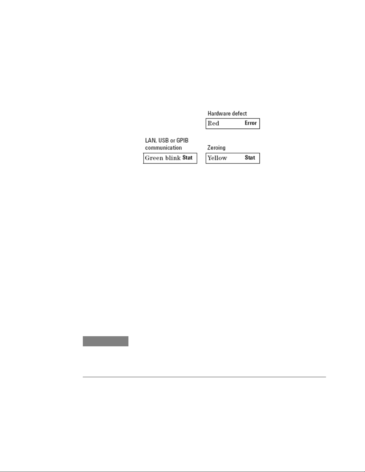
During operation, you may notice the following LED indicators:
Figure 16 Front Panel Indicators
Connecting to the Instrument
Connecting to the Instrument - Overview
When you are first connecting the instrument, we recommend you use
the Keysight Connection Expert included with the Keysight I/O
libraries (available on the CD supplied with the instrument, or from
www.keysight.com).
Connecting over USB
N O T E
The screenshots show the Keysight N7745A Multiport Power Meter. The same
procedure applies when connecting an Keysight N7744/7/8A Multiport Power
Meter, an Keysight N7751/2A Optical Attenuator and Power Meter, or an
Keysight N7761/2/4/6/8A Optical Attenuator or an Keysight N7711/4A
Tunable Laser System Source or an N773x Optical Switch.
30
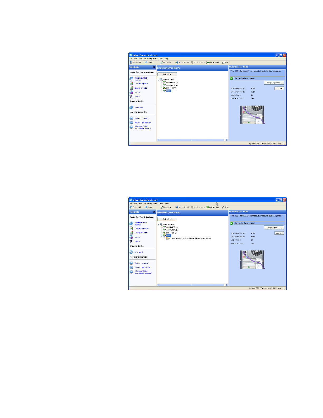
If it is not already running, start the Keysight Connection Expert
1
software.
Keysight N774x Series
Page 32
Getting Started 1
Figure 17 Keysight Connection Expert software
Attach the instrument to the USB. The first time you attach the
2
instrument, follow the instructions on the screen to select the driver
for this instrument.
When the instrument is connected, it is shown in the list.
Figure 18 Select the instrument in the list
Select the instrument in the list to see the associated tasks (in the
3
Task Guide on the left) and information (on the right).
Keysight N774x Series 31
Page 33
1 Getting Started
Finding the IP Address of an instrument
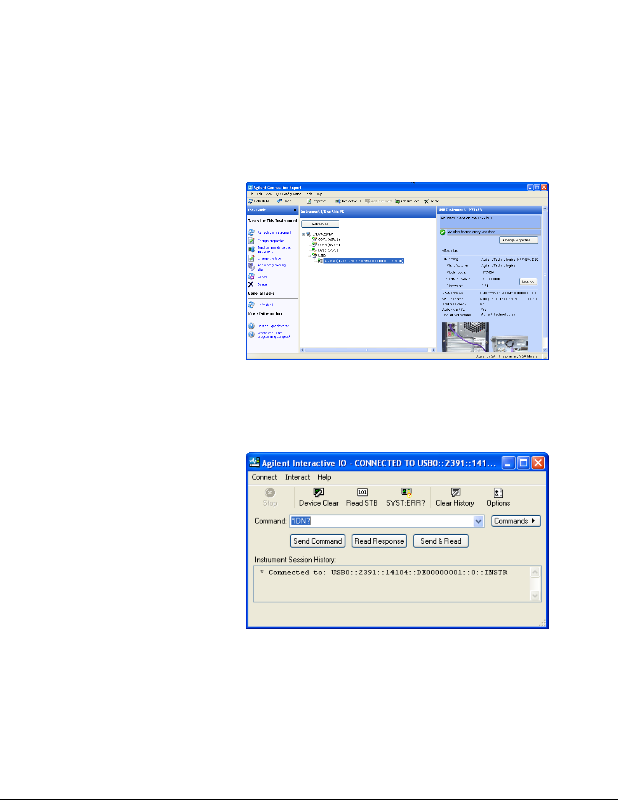
Connect to the instrument over USB, as described above.
1
Select the instrument in the list.
2
Figure 19 Select the instrument
Click on “Send commands to this instrument”.
3
The default command is the *IDN? query.
Figure 20 *IDN? query
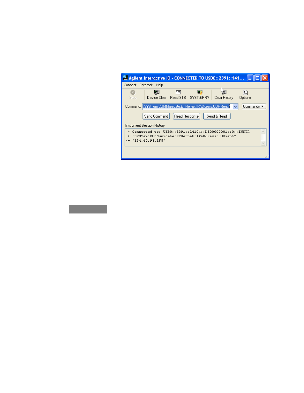
Enter the command
4
32
:SYSTem:COMMunicate:ETHernet:IPADdress:CURRent?
Keysight N774x Series
Page 34
Getting Started 1
then click on [Send & Read].
The instrument returns its current IP address.
Figure 21 :SYSTem:COMMunicate:ETHernet:IPADdress:CURRent?
Connecting over LAN
N O T E
The screenshots show the Keysight N7745A Multiport Power Meter. The same
procedure applies when connecting to other N77xx instruments like attenuators,
switches and laser sources.
Make sure the instrument is connected to the LAN, and that the LAN
1
LED on the front panel is green. See, “LAN Interface” on page 23 for
more information to connecting over LAN.
If it is not already running, start the Keysight Connection Expert
2
software.
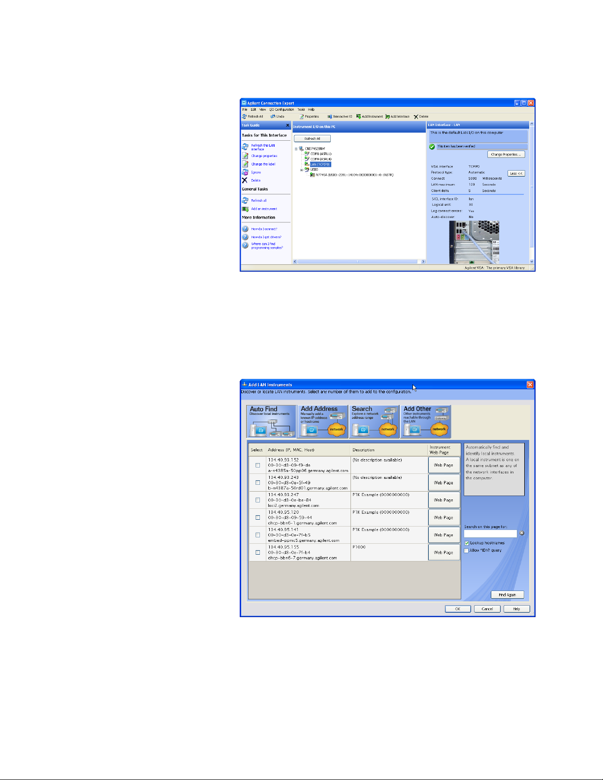
Select “LAN (TCPIP0)” in the list.
3
Keysight N774x Series 33
Page 35
1 Getting Started
Figure 22
Click on “Add an instrument” in the Task Guide.
4
Wait for the scan to finish.
5
Select the instrument in the list.
6
Figure 23
To show the description of the instrument, check the box for *IDN?
7
query and click on "Find Again".
34 Keysight N774x Series
Page 36
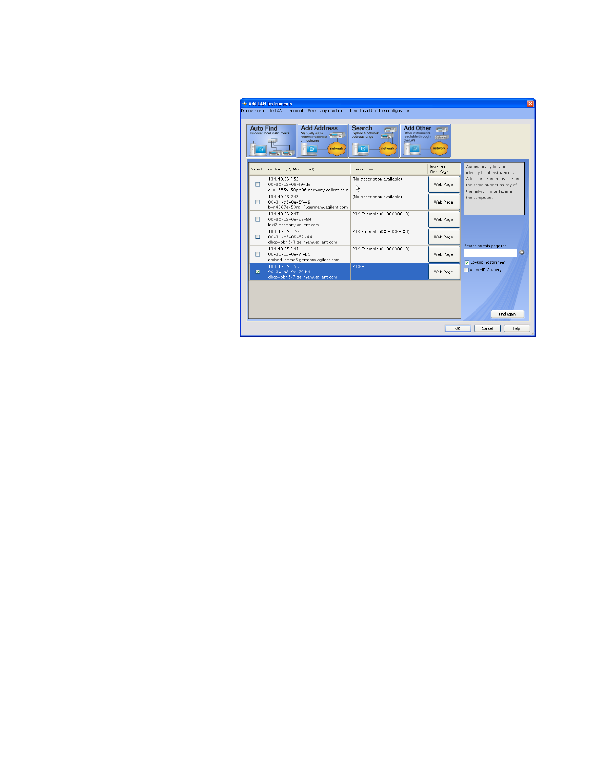
Getting Started 1
Figure 24
Select the instrument in the list to see the associated tasks (in the
8
Task Guide on the left) and information (on the right).
For the N774x Multiport power meters, click on the “Instrument Web
•
Interface” button to control the instrument directly.
Keysight N774x Series 35
Page 37
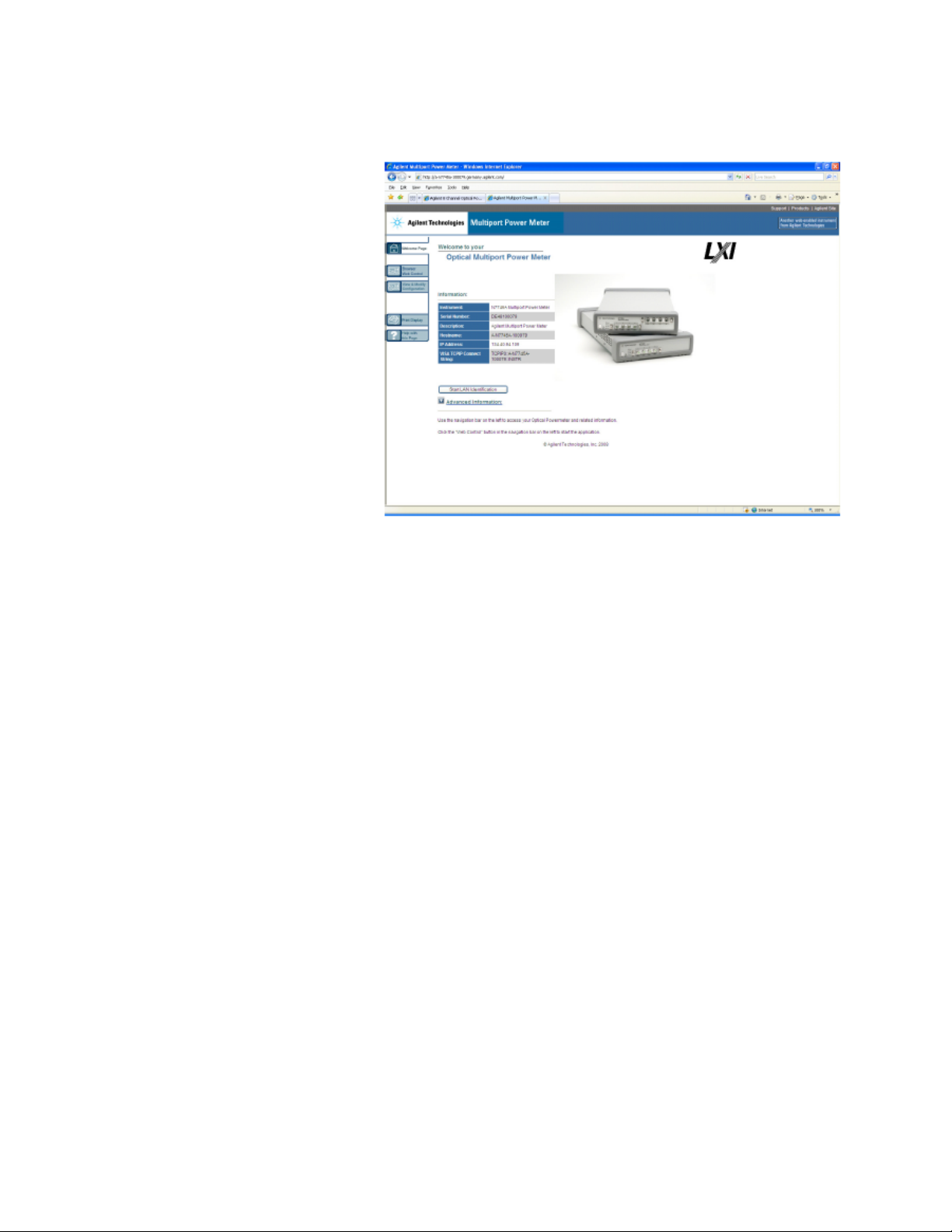
1 Getting Started
Figure 25
If it is not already installed, you will need to install a Java run-time
engine to use this page.
Basic configuration and functionality are available from this web
page.
You can control any of the instruments from the Keysight
•
N77xx Viewer.
– Connecting and using the N77xx Viewer is described in
“Connecting to the Instrument - Overview” on page 30.
More advanced functionality is available through programming with
SCPI commands (described in the Programming Guide available on the
CD supplied with the instrument or from www.keysight.com), or using
the 816x VXI Plug&Play driver, version 4.4.2 or higher. You can also use
the IVI-COM driver for the N7744A and N7745A Multiport power
meters.
36
Keysight N774x Series
Page 38

Claims and Repackaging
Claims and Repackaging - Overview
Return Shipments to Keysight Technologies
Getting Started 1
If physical damage is evident or if the instrument does not meet
specification when received, notify the carrier and the nearest
Keysight Technologies Sales/Service Office. The Keysight Technologies
Sales/Service Office will arrange for repair or replacement of the unit
without waiting for settlement of the claim against the carrier.
If the instrument is to be shipped to an Keysight Technologies
Sales/Service Office, attach a tag showing owner, return address,
model number and full serial number and the type of service required.
The original shipping carton and packing material may be reusable, but
the Keysight Technologies Sales/Service Office will provide
information and recommendations on materials to be used if the
original packing is no longer available or reusable. General
instructions for repackaging are as follows:
Wrap instrument in heavy paper or plastic.
•
Use strong shipping container. A double wall carton made of 350-
•
pound test material is adequate.
Use enough shock absorbing material (3 to 4 inch layer) around all
•
sides of the instrument to provide a firm cushion and prevent
movement inside container. Protect control panel with cardboard.
Seal shipping container securely.
•
Mark shipping container FRAGILE to encourage careful handling.
•
In any correspondence, refer to instrument by model number and
•
serial number.
Deleting user data
If you need to delete all your logged data and user configurations, that
is to reset the instrument completely:
Keysight N774x Series 37
Page 39
1 Getting Started
Press and hold the Reset/standby button until the instrument starts
1
to reboot.
When the instrument reboots, press the Reset/standby button once
2
more briefly, to confirm you want to delete all the stored data.
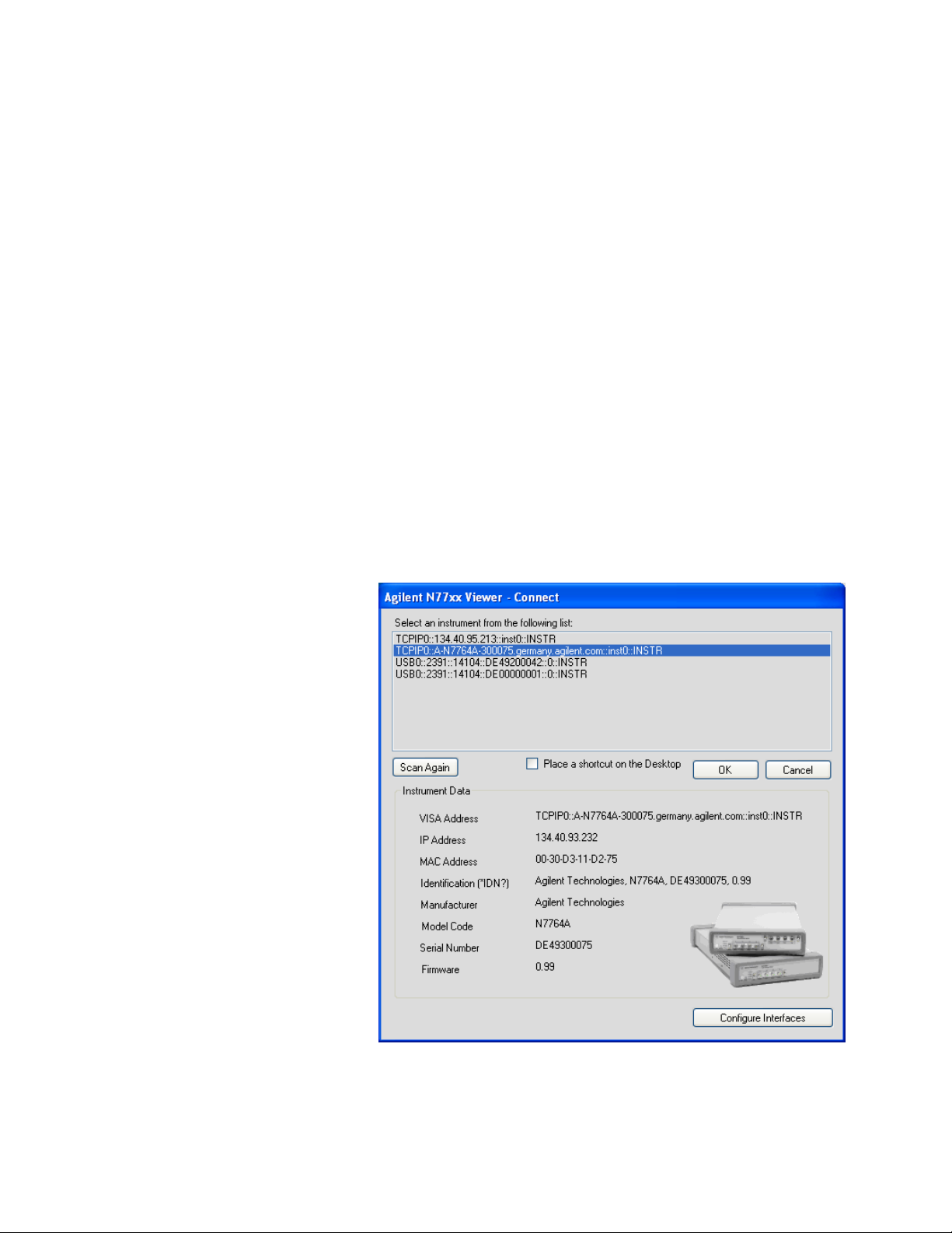
N77xx Viewer Common User Interface Functions
Connecting to an Instrument
When you first launch the N77xx Viewer, it is not connected to any of
your instruments.
Click on the “Connect” icon at the top right of the window.
1
Select the instrument to which you want to connect from the list.
2
38
Figure 26 Connecting to an Instrument
Keysight N774x Series
Page 40
Getting Started 1
The list shows instruments that have been given a VISA address.
3
If your instrument is not in the list,
Use the Keysight Connection Expert to check your instrument
1
has a VISA address
Click on the “Scan Again” button.
2
Once communication has been established to the instrument, its
details are shown.
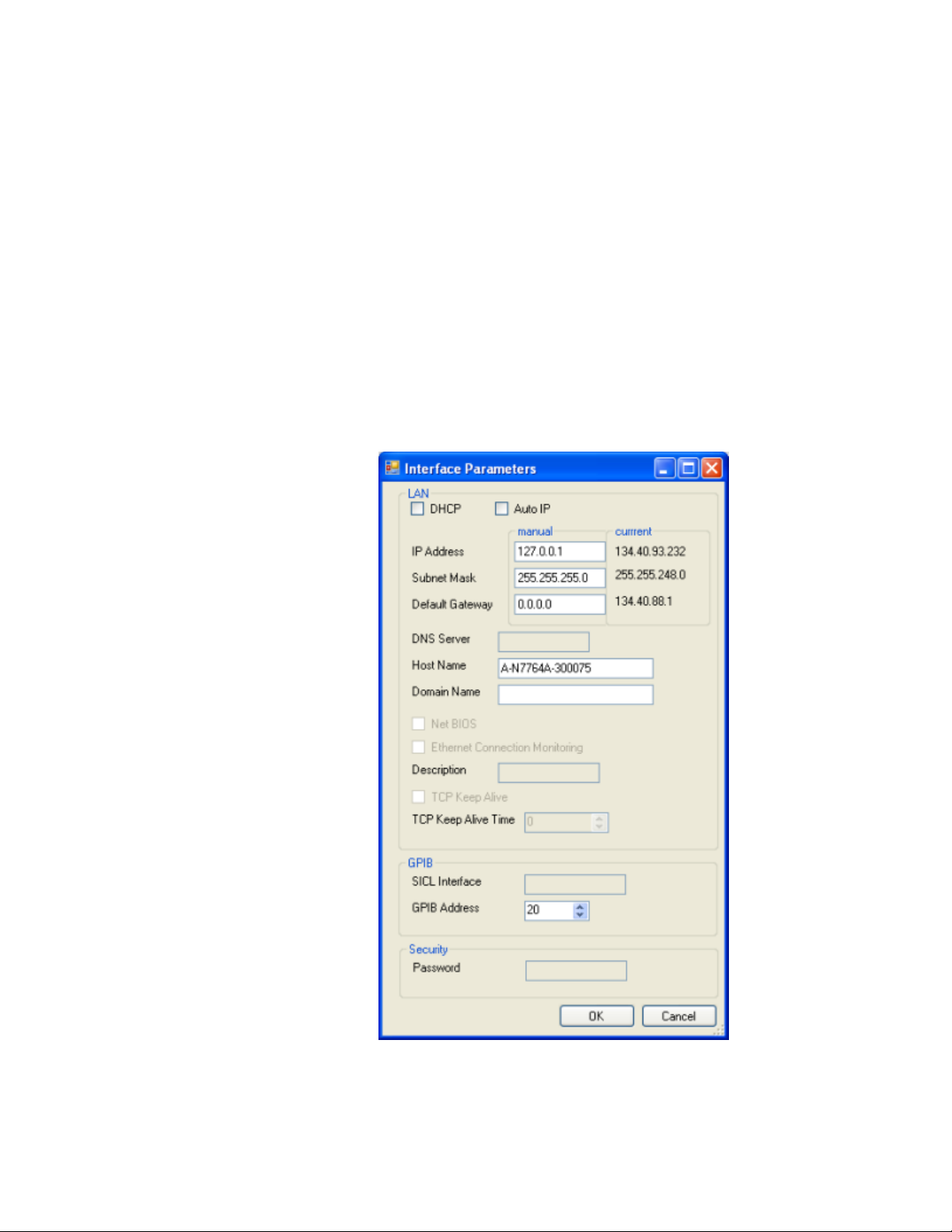
If you need to change the connection configuration for an instrument
4
on the LAN, click on the “Configure Interfaces” button.
You can only configure the LAN parameters before the instrument
is connected.
Figure 27 Interface Parameters
Keysight N774x Series 39
Page 41
1 Getting Started
– Make sure both DHCP and Auto IP are not selected.
– You can now edit the IP parameters.
For instruments you use regularly, you can add a link on your
5
desktop by putting a check mark in the box to “Place a shortcut on
the Desktop”.
Click on the “OK” button to finish the connection.
6
Viewing Measurements and Settings
The settings and readings of the instrument can be accessed directly
from the main Viewer panel. Instruments with multiple channels have
a tab for each channel. In addition, separate windows can be opened for
simply viewing the settings and readings, as follows:
Viewing the measurement on a single channel
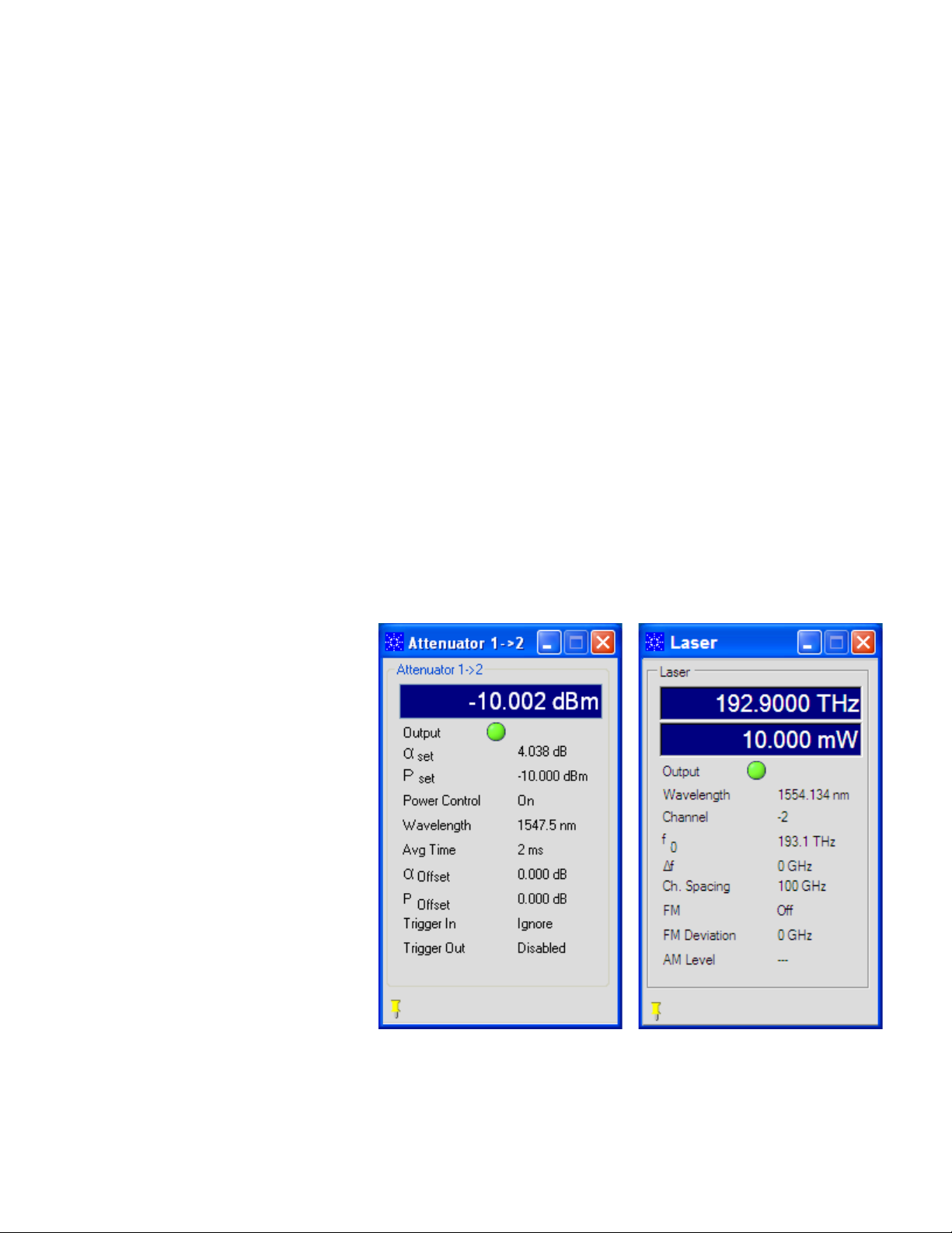
Click on the “New” button to open a window with the current
1
measurement and parameter settings.
40
Figure 28 Viewing the measurement on a single channel attenuator/power
meter (left) or tunable laser (right)
Keysight N774x Series
Page 42
Getting Started 1
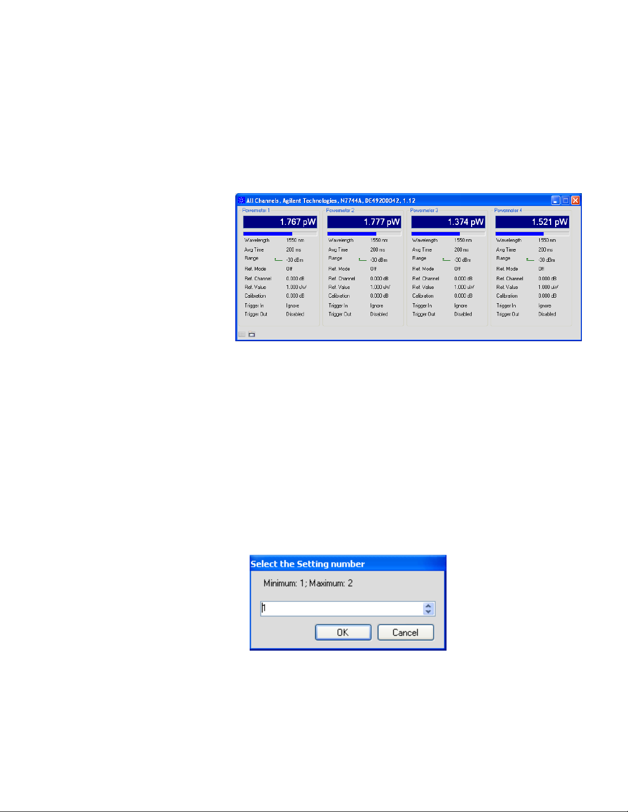
Viewing all channels
Click on "Overview" to open a window with the measurements on all
1
channels.
Figure 29 Viewing all channels
Saving and Recalling Configurations
Saving a configuration
You can save the current measurement configuration to either of two
settings stored on the instrument.
In the File menu, select Save.
1
Enter or select the setting to which you want to save it.
2
Figure 30 Saving a configuration
Click on the “OK” button.
3
Keysight N774x Series 41
Page 43
1 Getting Started
Recalling a configuration
In the File menu, select Load.
1
Enter or select the setting you want to retrieve.
2
Click on the “OK” button.
3
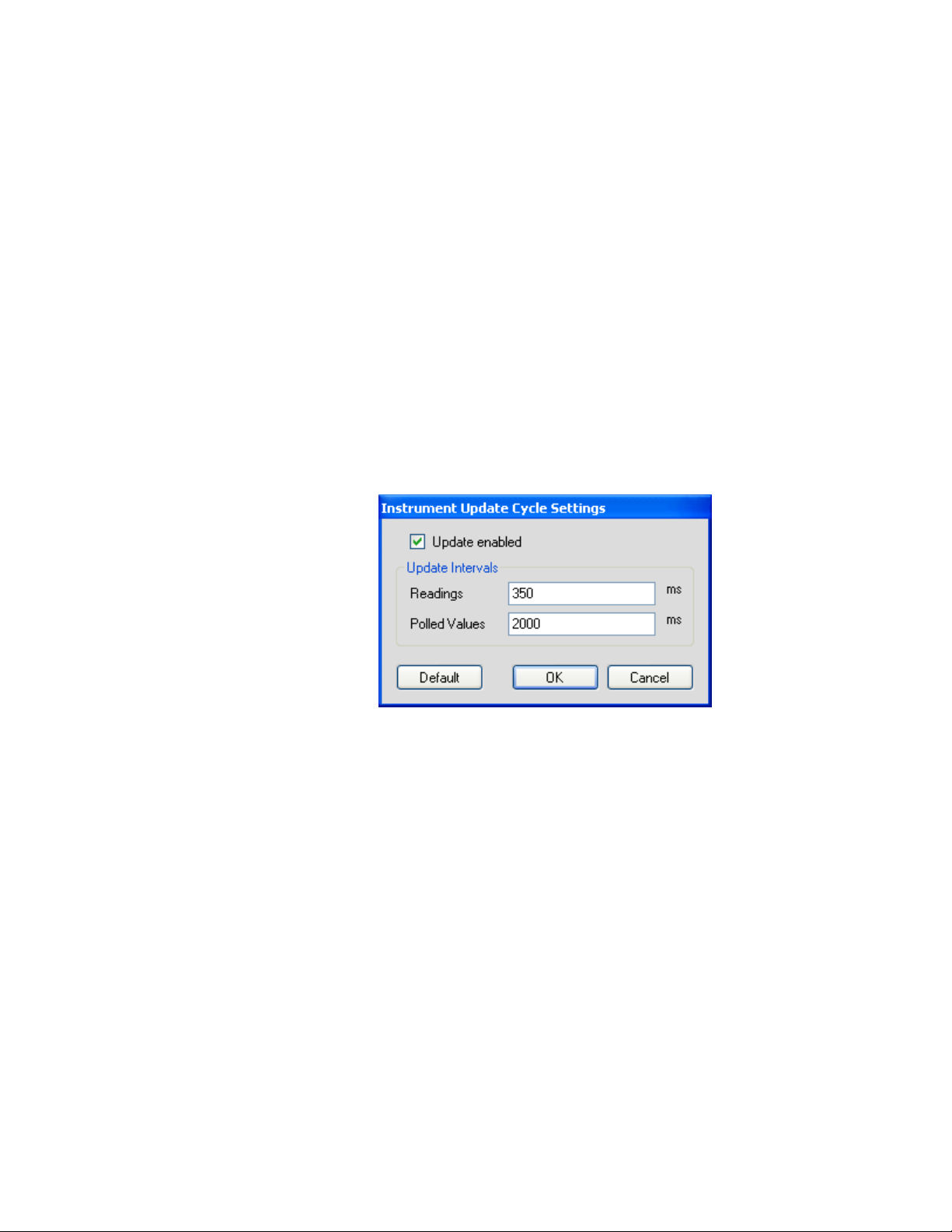
Controlling the Instrument Refresh
In the File menu, select Update.
1
In the dialog, you can :
Figure 31 Controlling the Instrument Refresh
Stop and start the display of all changes. Make sure to put a check
•
in the box for “Update enabled”, to enable the N77xx Viewer to
display the status and results from the instrument. If there is no
check in the box for “Update enabled”, the display is not updated
with the replies to queries sent to the instrument.
Set the update interval for “Readings” to control how often the
•
result is read from the instrument and the display updated.
Set the update interval for “Polled Values” to control how often
•
the measurement parameters are read from the instrument and
the display updated. This is useful if, for example, more than one
person can control the instrument.
When you have set all the values, click on the “OK” button.
2
42 Keysight N774x Series
Page 44

Power Measurement
Keysight N774x Series
User's Guide
2 Power Measurement
This chapter describes how to measure optical power using the
Keysight N7744A/N7745A/N7747A/N7748A Optical Multiport Power
Meter.
“Controlling the Optical Multiport Power Meter” on page 43
•
“The Power Value” on page 47
•
Controlling the Optical Multiport Power Meter
There are different possibilities to control the instrument:
LAN Connection: [Instrument Web Interface]
•
LAN / USB / GPIB Connection: [N77xx Viewer]
•
LAN / USB / GPIB: Programming with SCPI commands (described
•
in the Programming Guide available on the CD supplied with the
instrument or from www.keysight.com), or using the 816x VXI
Plug&Play driver. For the Keysight N7744A/N7745A Optical
Multiport Power Meter, you can also use the associated IVI-COM
drivers.
To connect to the instrument see “ Input and Output Connectors -
Overview” on page 18.
To display the Web Interface of the Multiport Power Meter please
either
Press the “Instrument Web Interface” Button within the Connection
•
Expert, or
Enter the instrument's IP Address or DNS Address in the Address
•
Line of your browser.
The browser starts with the screen shown in the figure, below.
43
Page 45
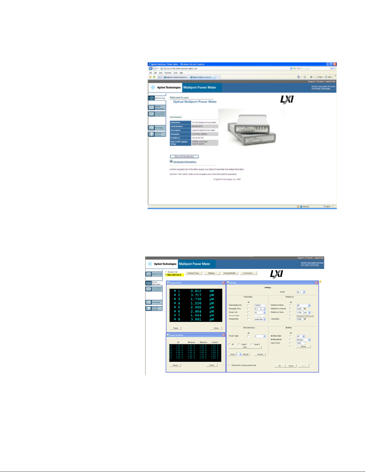
2 Power Measurement
Figure 32 The Welcome Page
Select the “Browser Web Control” tab on the left.
Figure 33 The Browser Web Control
44 Keysight N774x Series
Page 46
Power Measurement 2
How to Change the Settings of the Optical Multiport Power Meter
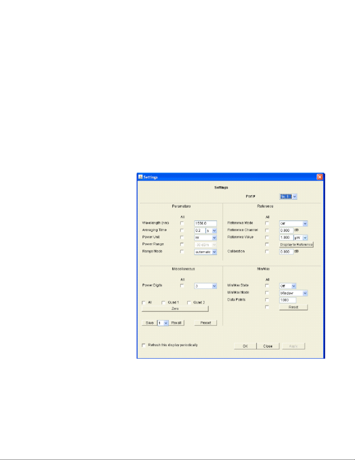
To change the settings of the Optical Multiport Power Meter from the
Browser Web control window, you must select the “Allow Full Control”
button. Now you are able to change the settings (see the figure, below)
of the Optical Multiport Power Meter. The changes are made when you
press the "Apply" button. If you selected the "All" checkbox, the setting
is applied to all ports.
To quickly and reproducibly set the measurement parameters, use the
Measurement Settings buffers. These let you save and recall sets of
settings with single programming commands. For further details, refer
to “Handling Measurement Settings The :CONFigure:MEASurement:SETTing subtree“ in the Programming
Guide.
Figure 34 Settings of the Optical Multiport Power Meter
Keysight N774x Series 45
Page 47
2 Power Measurement
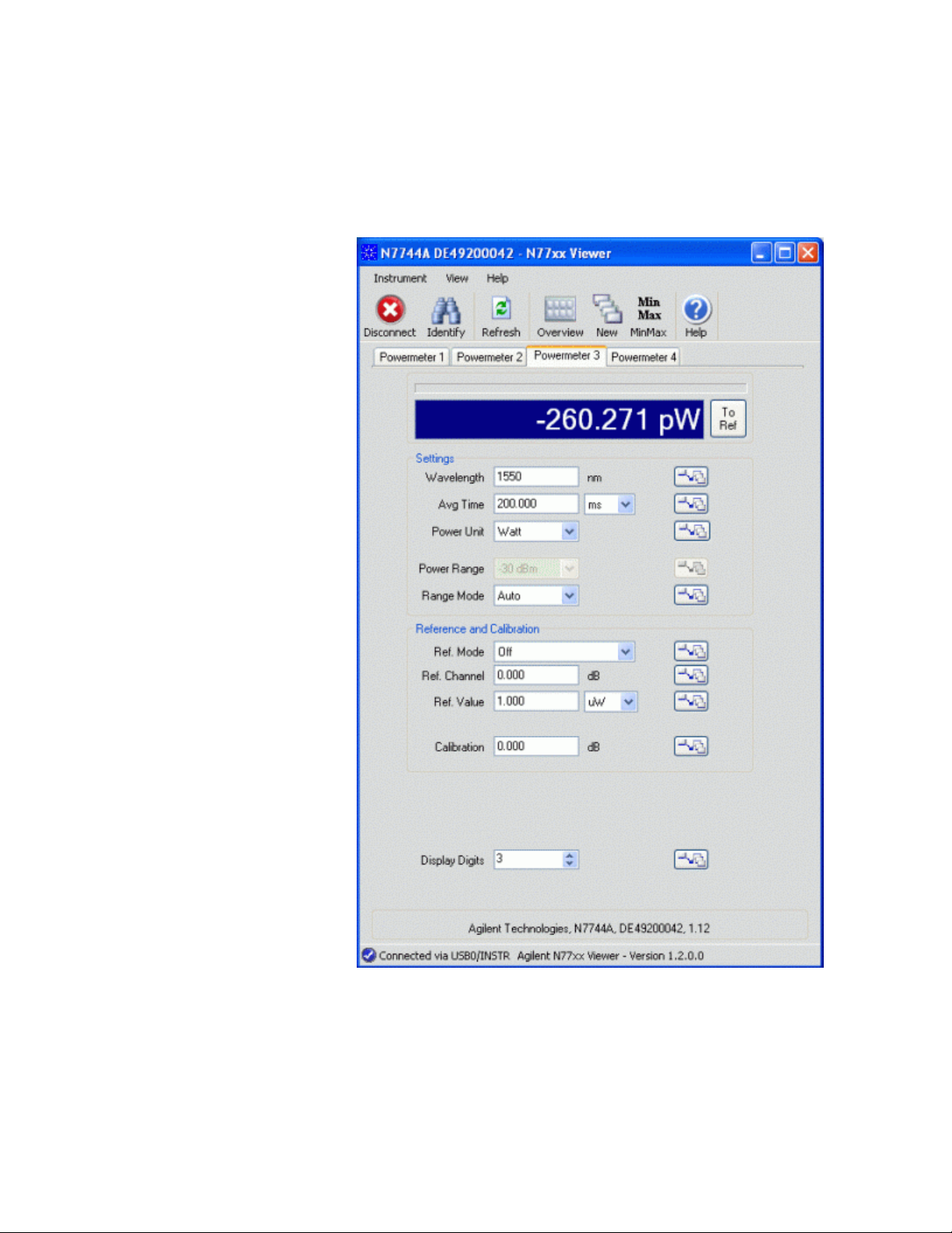
The most convenient way to control one or more Multiport Power
Meters is using the N77xx Viewer, which is a control and display
graphical user interface.
46
Figure 35 The N77xx Viewer
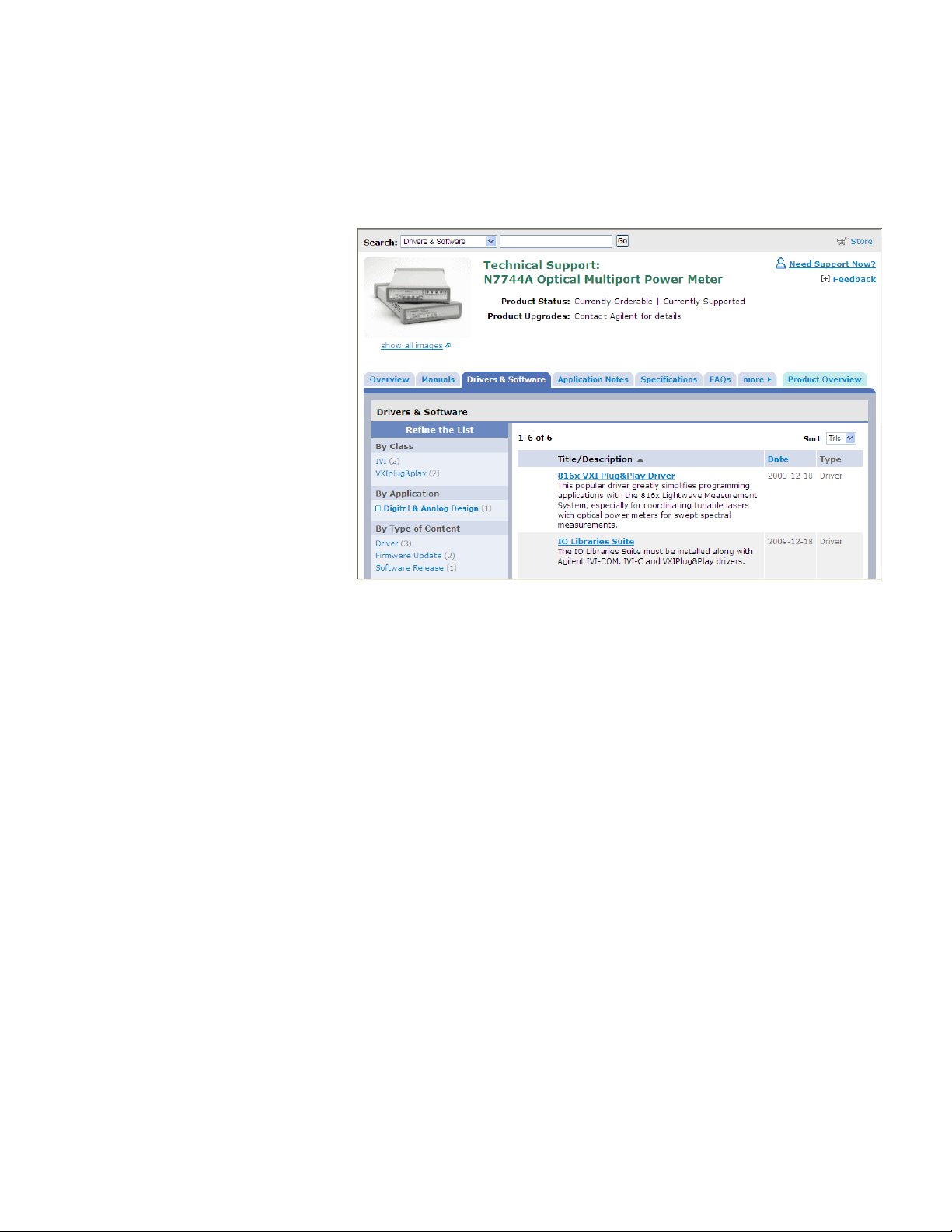
The Viewer is available to download from the product webpage which
you can access at
Keysight N774x Series
Page 48
Power Measurement 2
http://www.keysight.com/find/jet
Then select “Technical Support” followed by “Drivers & Software”.
How to Measure Power
The Power Value
Figure 36 Technical Support
On this webpage you will also find additional software tools like:
Firmware update utility
•
Firmware update file
•
VXI Plug&Play Drivers
•
IVI Drivers
•
For each port, the optical power is measured and returned or displayed.
The power reading represents the average optical power over the
selected averaging time. The power meter can continuously self-trigger
new measurements or be configured to wait for external software or
hardware triggers.
Keysight N774x Series 47
Page 49
2 Power Measurement
How to Set the Power Unit
How to Set the Number of Digits
When the power is displayed with the Web Interface or the Viewer
program, you can set the maximum number of digits that are used in
power measurement. This is the maximum number of digits after the
decimal point.
The Power Unit setting allows you to select either W, dBm or dB as the
units in which power is displayed or returned. For returning large
amounts of logged data, the fastest data transfer is achieved using W
units.
What are the Power Units?
Watts (W) are the SI unit for power measurement.
You can also measure power in dB or dBm. Values returned in these
units are derived from measurement in Watts.
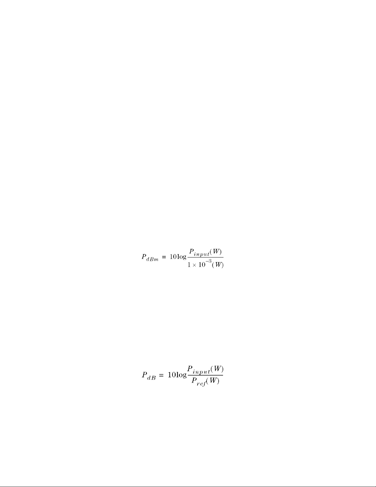
By selecting dBm, the following calculation is made:
Where,
P
is the power value returned in dBm, and
dBm
P
is the input signal level in Watts.
input
Power, in units of dBm, is measured relative to 1 mW. It is an absolute
power measurement.
Power, in units of dB, is measured relative to a particular reference
power value. For information on selecting this reference value, see How
to Input a Reference Level.
The following calculation is made:
Where,
PdB is the power value returned in dB,
P
is the input signal level in Watts, and
input
48 Keysight N774x Series
Page 50

P
is the chosen reference power value in Watts.
ref
How to Set the Calibration Offset
This is a calibration offset that you can enter to compensate for external
optical circuitry, for example, an attenuator, switch, or a 3 dB coupler.
The calibration offset, [Cal], is automatically subtracted from the input
signal, as expressed in dB.
where,
Power Measurement 2
P
measured
P
input
is the adjusted value of the signal read in dBm,
is the input signal level in dBm, and
CAL is the calibration offset in decibels (dB).
How to Set the Reference Level
How to Input a Reference Level
dB results are shown relative to a reference level. Setting, or changing,
the reference only affects results that are returned in dB.
You can set the reference level in units of dBm or Watts. Depending on
which is selected the following equations are used to calculate the
power level in dB:
PdB = P
or
measured
(dBm) - REF(dBm)
where,
PdB is the returned relative power,
P
measured
is the absolute power level (see “How to Set the Calibration
Offset” on page 49), and
REF is the reference level.
Keysight N774x Series 49
Page 51
2 Power Measurement
How to Set the Reference Value to the Current Power Value
In addition to entering a new reference value, you can change the
reference value to the current power value from the N77xx Viewer or
by programming.
This takes the input power level and stores it as the reference. Setting
the reference only affects results returned in dB.
The power value in dBm or Watts is stored as the reference, that is:
REF = P
measured
where,
REF is the reference, and
P
measured
is the absolute power level (see “How to Set the Calibration
Offset” on page 49).
How to Reference Another Power Measurement Port
You can use the reference mode to reference to another port’s current
power level. If you choose this mode, the reference of the port
continuously updates to the current power value measured by the other
port.
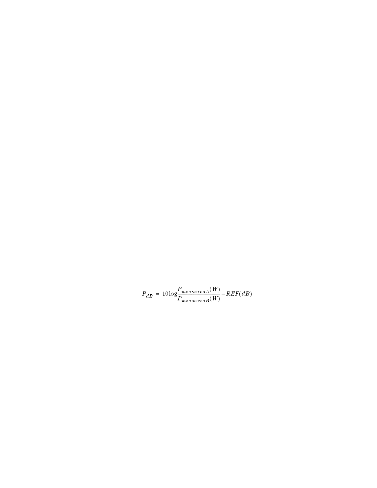
The following equations describe how the power in dB is calculated if
you reference another port:
PdB = P
or
where:
measuredA
(dBm) - P
measuredB
(dBm) - REF(dB)
50
PdB is the relative power,
P
measuredA
is the absolute power level (see “How to Set the Calibration
Offset” on page 49) measured by the current port, and
P
measuredB
is the absolute power level (see “How to Set the Calibration
Offset” on page 49) measured by the port you choose to reference, and
REF is the reference level in decibels (dB).
Keysight N774x Series
Page 52

How to Set the Wavelength
This is the wavelength value of the signal to be measured. The
responsivity of the Power Meter varies with wavelength.
For accurate absolute power measurement, you need to input the
wavelength of the optical input.
For relative power measurements, this setting is not critical.
How to Remove Electrical Offsets (Zero)
Optical Power Meters measure optical power by converting optical
power to electrical current, and then measuring electrical current. An
electrical offset is electrical current that is always present, even if there
is no optical power input. If electrical offsets are not removed, they
affect the accuracy of power measurement, especially at low optical
power levels.
Power Measurement 2
N O T E
Performing a zero sets the zero power level to the average electrical
offset level for the current environmental conditions.
The environmental conditions and the temperature of the instrument NOTE affect
electrical offset.
For the best results you must:
Allow the instrument time to acclimatize (around 24 hours).
•
Allow the instrument time to warm up (around 20 minutes).
•
Make sure that the optical input is not receiving any light or use the
•
zeroing adapter. If you are using multi-mode fiberoptic cable, you
must disconnect the cable and cover the input to the Power Meter to
perform a zero.
It is good practice to perform a zero before making any sensitive
measurements.
Logging data over a wide dynamic range is a typical case that requires
a valid zero setting.
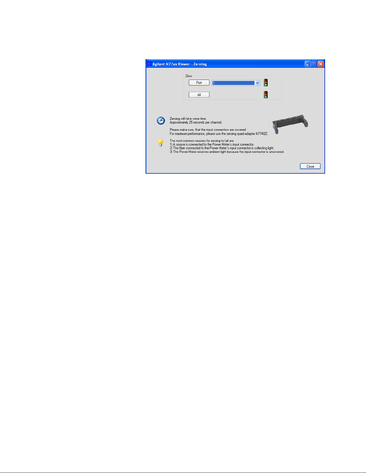
In the File menu, select Zeroing.
1
Keysight N774x Series 51
Page 53
2 Power Measurement
Figure 37
Select the channel you want to zero from the drop down list and click
2
on the “Port” button.
OR
Click on the “All” button.
While the zero is running, the traffic light flashes amber.
If you receive a zero error, the zeroing operation has failed because
the Power Meter received light. The most common reason for zeroing
to fail is if:
a source is connected to the Power Meter’s input connector,
•
the fiber connected to the Power Meter’s input connector is
•
collecting light, or
the Power Meter receives ambient light because the input
•
connector is uncovered.
When zeroing is finished, the traffic light is green. You can now
proceed with your measurements.
When environmental conditions are stable, the zero setting will remain
valid over long times and the same settings will be active after rebooting
the instrument.
52 Keysight N774x Series
Page 54

How to Choose the Range Mode
You can choose either of two ranging modes:
<Auto>, the auto-ranging mode, ensures that the result has a
•
returned value between 9% and 100% of full scale. The default state
is for automatic ranging to be enabled.
<Manual>, which allows you to set a user-defined range.
•
How to Set the Range
The range setting determines the power levels that can be measured.
The setting should be high enough for the applied power, but lower
settings will provide a lower noise level for weak signals.
If you choose auto-ranging mode, this parameter can not be set. The
Range parameter returns the automatically-determined range.
Power Measurement 2
If the measured power is more than 3dB greater than the range setting,
the power cannot be measured and an overflow is indicated by the
returned power value. This means that the measured power is greater
than the Upper Power Limit. You must increase the [Range] value.
More more details, see the following table.
Upper Power Limit
The following table shows the upper power limit at the available power
ranges. The lowest measurable power in each range is determined by
the noise level, which depends on the range setting and the averaging
time.
Table 3
[RANGE] Upper Power Limit
10 dBm 10.000 mW 10.000 dBm
0 dBm 1.9999 mW 3.000 dBm
-10 dBm 199.99 µW -7.000 dBm
Upper Power Limits for Various Power Ranges
-20 dBm 19.999 µW -17.000 dBm
-30 dBm 1.9999 µW -27.000 dBm
Keysight N774x Series 53
Page 55

2 Power Measurement
Table 3
[RANGE] Upper Power Limit
-40 dBm 199.99 nW -37.000 dBm
-50 dBm 199.99 nW -47.000 dBm
-60 dBm 199.99 nW -57.000 dBm
-70 dBm 199.99 pW -67.000 dBm
Upper Power Limits for Various Power Ranges
How to Set the Averaging Time
This is the length of time over which a signal is averaged to produce a
measured value. Longer averaging times increase the accuracy and
improve the noise rejection.
The averaging time of the N7744A and N7745A can be set over a wide
range from 1 µs to 10s. Up to 2 ms, the setting can be varied with a typical
resolution of 2 µs, and for higher averaging times the setting resolution
is about 0.1%. This flexible setting time supports optimal
synchronization with the time scale of the signals. The high sampling
rate with short averaging times is supported by the high cutoff
frequency, as shown in the specifications. These bandwidths are
reduced in steps, when longer averaging times are used to improve the
noise performance while maintaining signal fidelity.
For the N7747A and N7748A, the averaging time can be set from 25 µs
to 10 s. Up to 2 ms, the setting can be varied with a typical resolution
of 2 µs, and for higher averaging times the setting resolution is about
0.1%. The bandwidth is fixed with the chosen power range, as listed in
the specifications and independent of the selected averaging time.
Individual values for live readings and for the MinMax mode, are
generated with a minimum resolution of 1 ms. This limit does not apply
to the Logging and Stability functions.
How to Set Automatic Gain for Averaging Modulated Signals
A fast Auto Gain switching is used to achieve the high dynamic range
in the N7744A and N7745A. In some applications, like determining the
average power of signals modulated with periods shorter than the
averaging time, this switching produces irregular readings. In such
54 Keysight N774x Series
Page 56
cases, the Auto Gain should be turned off, as described in the
programming guide. This setting takes effect after setting the averaging
time on the port directly or via function parameters.
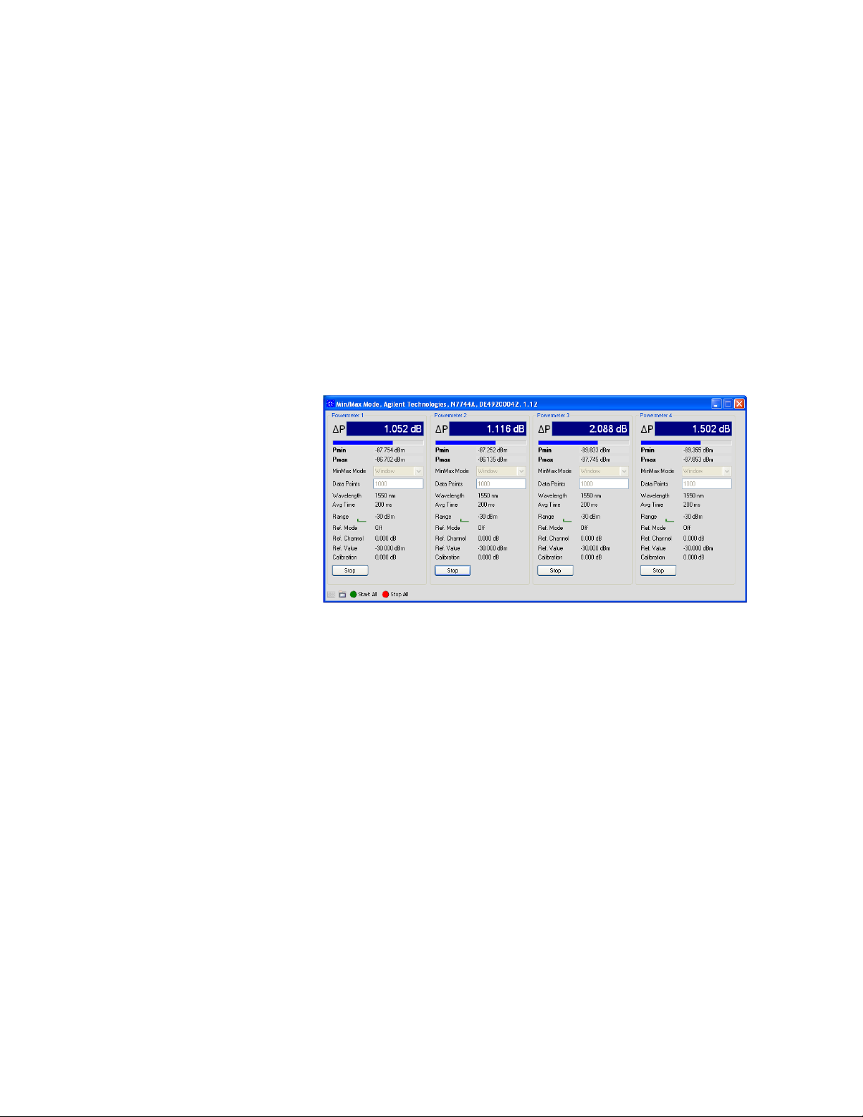
How to Choose the MinMax Mode
MinMax mode measures the incoming power and returns the minimum
value measured, and the maximum value measured. The difference
between these values, delta P, is returned in place of P, the power value.
This mode is intended principally for polarization dependent
measurements, but can be used for other types of measurement.
Power Measurement 2
Figure 38 How to Choose the MinMax Mode
The Min/Max mode can be activated from both the Web Control
Interface and the N77xx Viewer, as well as with direct programming
described in the Programming Guide.You can choose two modes of
operation from the MinMax mode menu:
<Continuous> mode, which compares each new measured value with
•
the maximum and minimum values so far, and replaces them as
necessary.
This mode is useful for measuring the Polarization Dependent Loss
(PDL) of a component. Run the application while sweeping the
polarization of the source applied to the component.
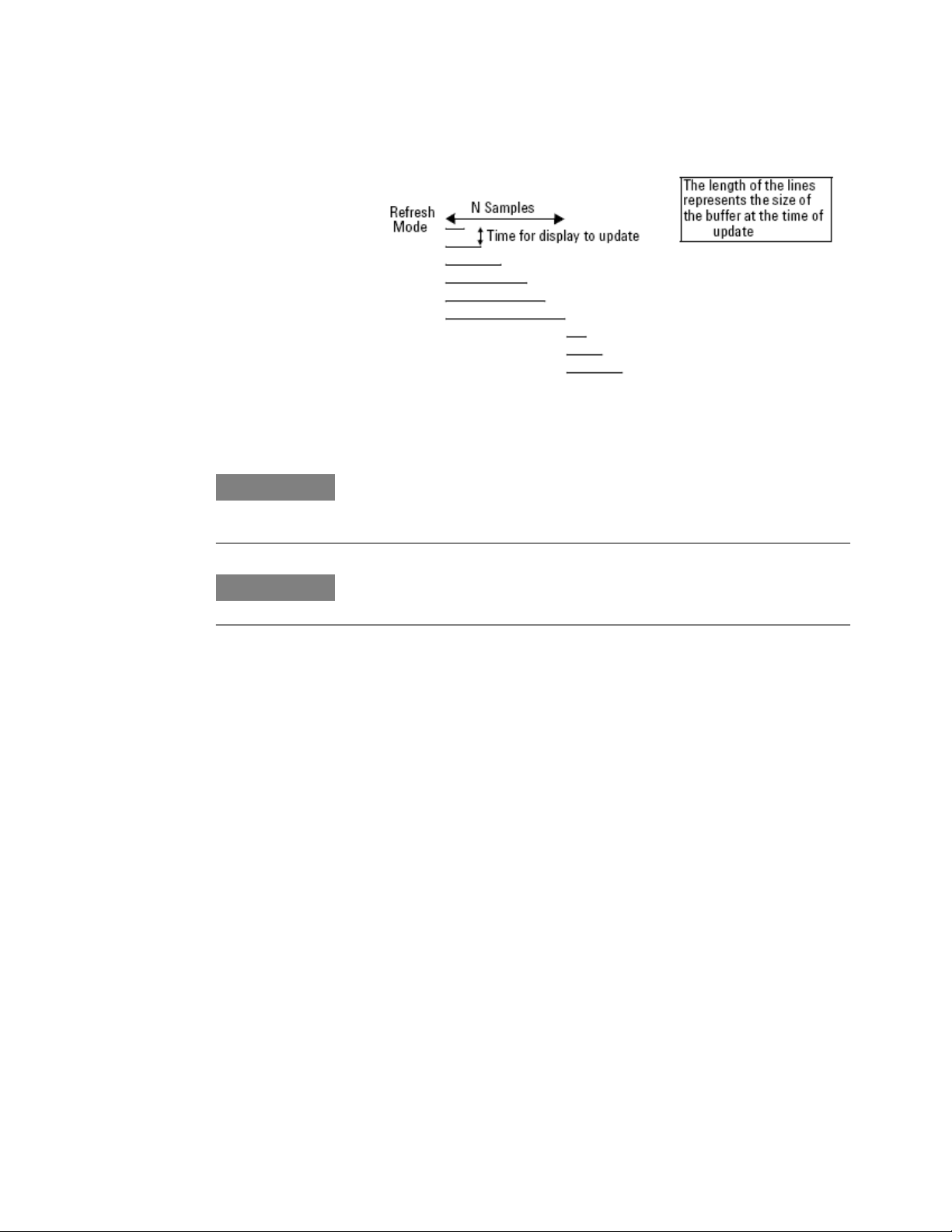
<Refresh> mode, which records the minimum and maximum values
•
until N samples have been compared. After N samples the minimum
and maximum values are reset and a new MinMax measurement
begins.
You can use Refresh mode, for example, when you are searching for
or setting the position of minimum PDL.
Keysight N774x Series 55
Page 57
2 Power Measurement
Figure 39 Refresh Mode
N O T E
N O T E
Window mode is not currently implemented in the N774xA and N775xA. For
compatibility with existing software it can be selected but functions the same as
Refresh mode.
The minimum sampling period in Min/Max mode, dependent on the rate of
commands and number of active ports, is about 2 ms.
How to Use External Triggers
The Optical Multiport Power Meter lets you trigger the instrument to
perform tasks and to output trigger signals to external measurement
instruments using the rear panel BNC connectors.
In the File menu, select Trigger.
1
56
Keysight N774x Series
Page 58
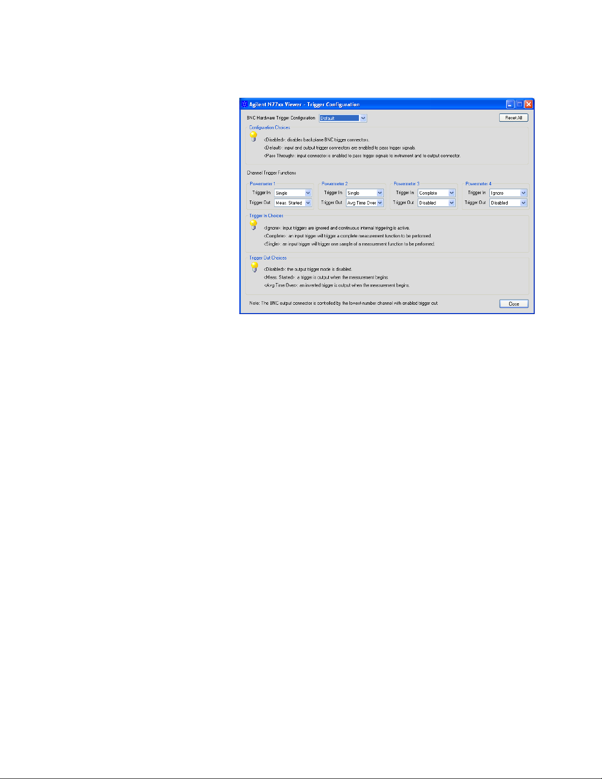
Figure 40 Trigger Configuration
Power Measurement 2
Set the trigger configuration
2
By default, the trigger level at the external trigger connector is active
high. This means when a trigger rises above the high TTL level (rising
edge), a trigger is accepted.
You can select three modes of triggering from the trigger
configuration menu:
<Disabled>, if you do want to disable triggering.
•
<Default> to enable the trigger connectors.
•
<Pass Through> if you want an input trigger to automatically
•
generate an output trigger. This lets you trigger another
instrument almost simultaneously.
Set the input trigger functions
3
The power meter ports can be configured individually to respond to
an input trigger by:
<Ignore> The trigger is ignored.
•
<Single Measurement> The trigger causes a single power
•
measurement to be made.
<Complete Measurement> The trigger will cause an active
•
measurement function like logging to begin and continue until
completed.
Set the output trigger functions
4
Keysight N774x Series 57
Page 59

2 Power Measurement
The power meter ports can be configured individually to generate
output triggers for the following events:
<Disabled> No triggers are generated.
•
<Meas. started> An output trigger is generated when a power
•
measurement begins.
<Avg Time Over> An inverted trigger is generated for each
•
measurement sample.
For further information on triggering, please refer to the Keysight
N77xx-Series Programming Guide, in the chapter “Triggering - The
TRIGger Subsystem”.
58
Keysight N774x Series
Page 60
Power Meter Applications
Keysight N774x Series
User's Guide
3 Power Meter Applications
This chapter explains how to set up and perform the following
applications using the N7744/5/7/8A Optical Multiport Power Meter.
The Logging application logs power measurements. The Logging
•
application performs measurements consecutively without the
possibility of any pause between measurements.
The Stability application logs power measurements. The Stability
•
application differs from the Logging application because:
– the period time, the time it takes from the start of one
measurement period until another measurement period starts,
may be greater than or equal to the averaging time.
These applications can be accessed with programming commands as
described in the Programming Guide.
“The Logging Application” on page 59
•
“The Stability Application” on page 61
•
The Logging Application
The Logging Application logs a series of power measurements for a
number of power meter ports.
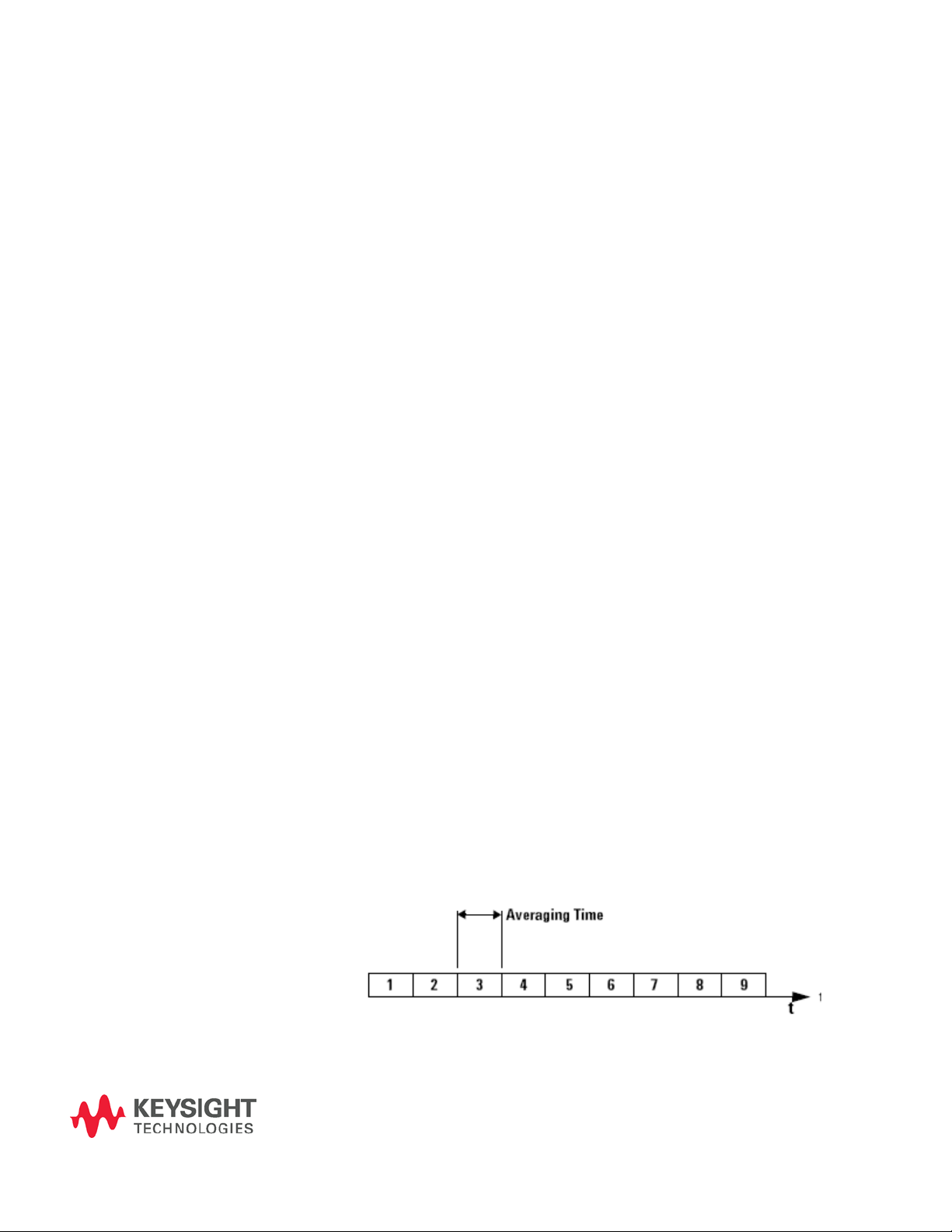
Figure 41 Example Logging Application
59
Page 61

3 Power Meter Applications
The most important parameters for the logging application are:
[Samples], this is the number of samples that will be performed
•
during the logging application, and
[AvgTime], the averaging time is the length of time over which a
•
signal is averaged. Longer averaging times increase the accuracy and
improve the noise rejection. Longer averaging times also improve
sensitivity.
The total time for a logging application is the number of samples
multiplied by the averaging time. The power range is constant during a
logging application and autoranging is disabled.
The Logging application differs from the “The Stability
Application” (see, “The Stability Application” on page 61) because all
power measurements are performed consecutively without the
possibility of any pause between measurements, as shown in the
figure, above.
While performing the logging application all used ports of the
instrument will have the same averaging time and number of samples.
Setup parameters for each of the ports should be set before the logging
is started on any port. Only N7747A and N7748A allow different settings
for logging parameters on each channel.
The logging function is often used together with single-measurement
input triggering for synchronized measurement with another
instrument, especially for spectral measurements with a tunable laser.
Continuous Logging Using Data Buffers
Enhanced logging functionality is available using two data buffers for
each port.
The MPPM ensures there is no time lag between logging and data
availability by using a data buffer with a capacity of 1M samples for each
channel. You can read the most recent results out of one buffer out while
the next logging measurement is filling the other buffer.
You can use this to speed up applications with repeated logging
operations. It is especially valuable for monitoring signals over
extended periods to detect transient events.
To use the data buffers, set the logging function to perform a fixed or
indefinite number of "LOOP"s, as described in the Programming Guide.
When LOOP = 1, default logging behavior is selected, that is
•
measurements are made and the results are written to the first
buffer.
If LOOP = 0, logging continues, writing the results into alternate
•
buffers, until you stop it.
60
Keysight N774x Series
Page 62
When LOOP = n>1, then upon completion of a logging measurement,
•
another is started and the results are written in rotation to the two
buffers (first to buffer A, then buffer B, then buffer A, and so on).
This is repeated until n logging measurements have been performed.
For example, if n=2, both buffers are filled, and you can upload a
total of 2M samples for the channel.
You can also use input triggers to begin individual loops or to begin
multiple loops with an initial trigger.
The "Index" value is updated to indicate that data from each LOOP
is available for readout.
The Stability Application
The Stability Application logs a series of power measurements for a
number of power meter ports.
Power Meter Applications 3
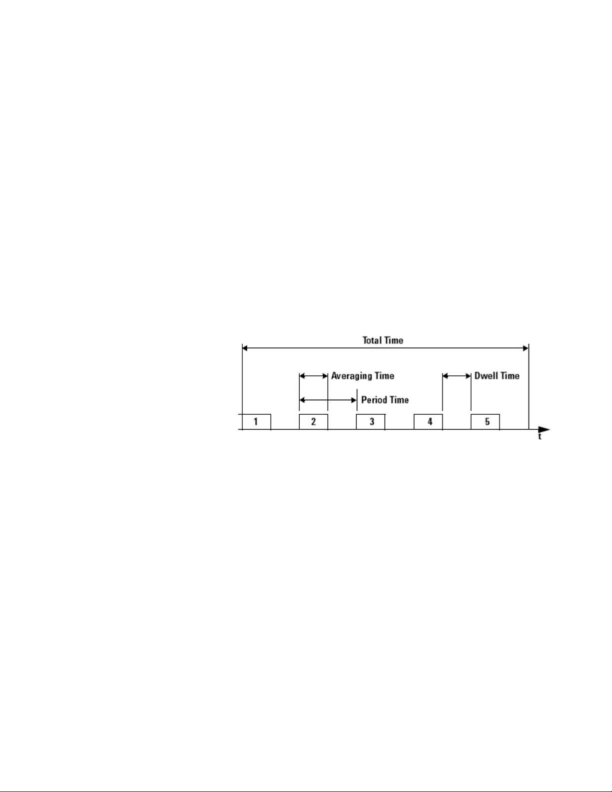
Figure 42 Example Stability Application
The Stability application differs from the “The Logging Application”
because you set the averaging time, the total time, and the period time
after which each new measurement is started. Period time must be
greater than or equal to the averaging time you set.
This leaves the following two possibilities:
The averaging time is less than the period time, there is a dwell time
•
between the commencement of each power measurement, as shown
in the figure, above.
The averaging time is equal to the period time, all power
•
measuremant are performed without any dwell time.
Keysight N774x Series 61
Page 63

3 Power Meter Applications
N O T E
The total time concludes after the last dwell time period, not after the last averaging
time period.
The Stability application enables you to make periodic power measurements over
a long time (277 hours (11 days and 13 hours)).
62
Keysight N774x Series
Page 64

Keysight N774x Series
User's Guide
4 Specifications and Regulations Compliance
Definition of Terms
(Applicable) fiber type
Connection type for which the specifications and characteristics apply
(if not differently stated).
Averaging time
Specifies the period during which the power meter or monitor power
meter takes readings from the photodetector. The displayed power
result is the (arithmetical) average of these readings.
Constant operating conditions
This generally includes constant values of temperature, humidity,
wavelength, input power level, polarization state and mode
distribution, if the quantity is not explicitly subject to variation.
Data logging capability
Maximum number of power readings per port that can be captured
during a logging operation.
Drift (dark)
Specifies the maximum deviation from zero of the measured power with
no optical input (dark) over time, excluding “Noise pp (dark)” on page
65, power expressed in Watts.
Measurement: From the dark measurement result Pi, a polynomial fit
Fi is calculated. The fit incorporates the least square-sum difference and
63
Page 65
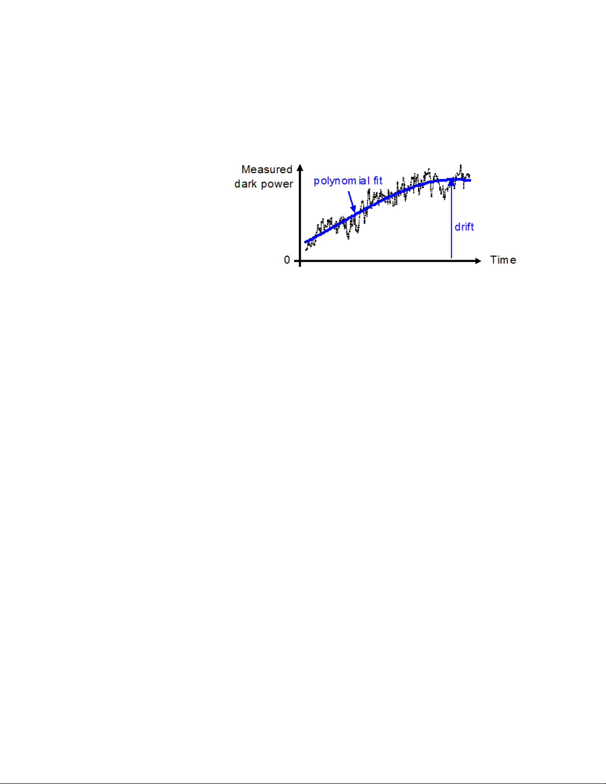
4 Specifications and Regulations Compliance
uses 3rd-order for the N7744A and N7745A and 1st-order for the
N7747A and N7748A. The Drift D is calculated by
D = maxi{Fi} or mini{Fi}, whichever is worse.
Figure 43 Drift (dark)
Conditions: All ports dark. Observation time as specified. Other
conditions as specified.
Dynamic range (logging mode)
For a fixed power meter range, dynamic range D specifies the difference
between the maximum displayable value P
in dBm in the
max
corresponding power meter range and the minimum measurable power
P
in dBm.
min
Conditions: As specified.
Measurement: P
(that is, in the +0 dBm power meter range P
the +10 dBm range with P
is 3 dB above the nominal power meter range value
max
is +3 dBm), except for
max
= +10 dBm. P
max
,dBm is calculated as the
min
root-sum-square (RSS) of the specified “Noise 2 sigma (dark)” (see,
“Noise 2 sigma (dark)” on page 66 and “Drift (dark)” (see, “Drift
(dark)” on page 63. RSS is calculated in linear units (Watts).
Frequency Response
Specifies the frequency f
function is above a defined cutoff level.
The transfer function is the measured optical amplitude on a modulated
sinusoidal optical input divided by the actual amplitude over
modulation frequency, expressed in dB.
up to which the power meter's transfer
resp
64
Conditions: Cutoff level as specified. Other conditions as specified.
Keysight N774x Series
Page 66
Specifications and Regulations Compliance 4
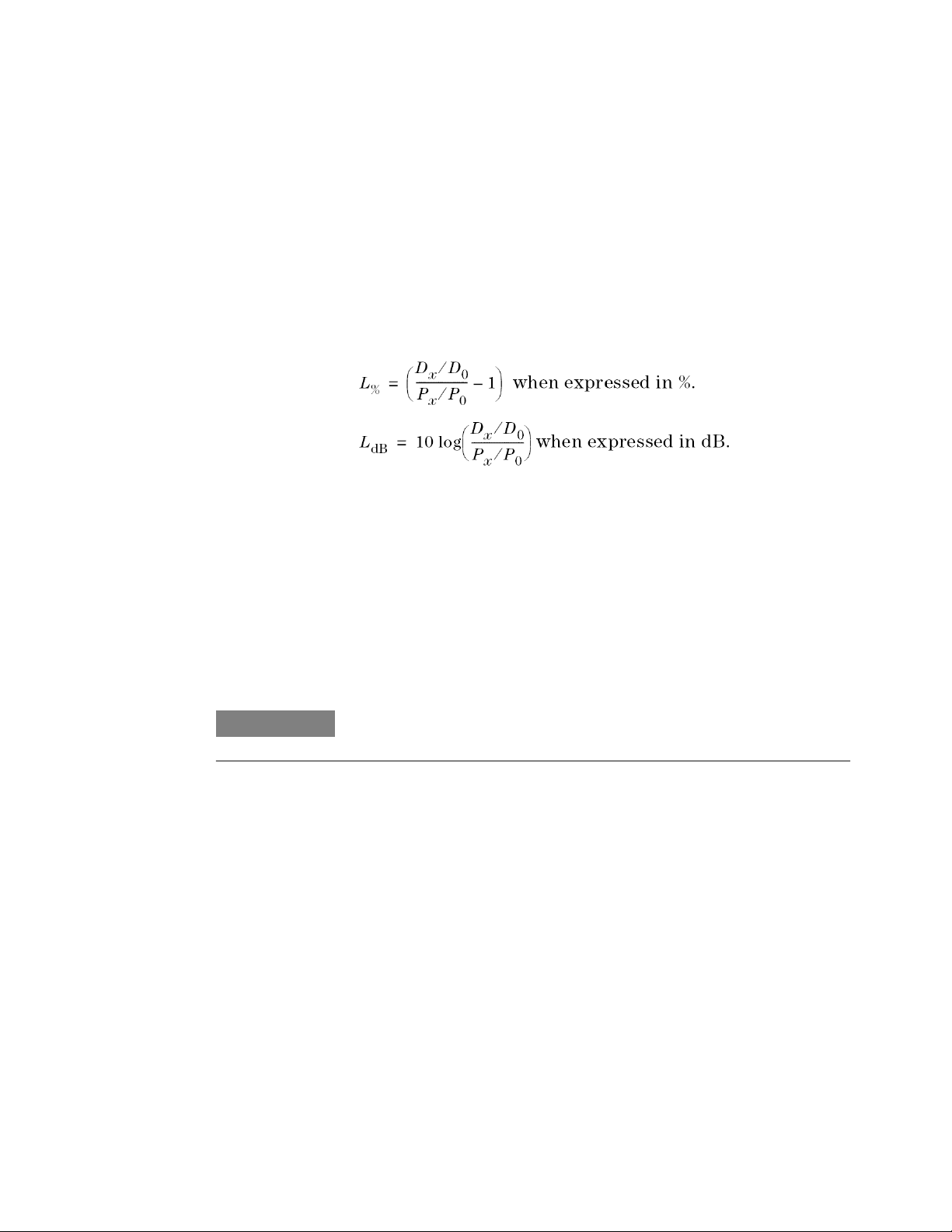
Linearity
Specifies the relative difference between the measured (displayed)
power ratio Dx/D0 and the actual (true) power ratio Px/P0, caused by
changing the power level from the reference level P0 to an arbitrary level
Px.
Powers expressed in Watts.
Excluding “Noise pp (dark)” (see, “Noise pp (dark)” on page 65 and
“Drift (dark)” (see, “Drift (dark)” on page 63).
Conditions: Reference power level P0 = 0.01 mW (-20 dBm). Other
conditions as specified.
N O T E
Maximum safe (input) power
The maximum input power that can be applied to any port of the power
meter or attenuator without permanent change to its characteristics.
Attention: Applying more than the specified power might damage the
power meter or attenuator!
For input powers > 20 dBm, clean connectors in good condition are vital to avoid
thermally induced fiber damage.
Minimum averaging time
The minimum selectable averaging time.
Noise pp (dark)
Specifies the peak-to-peak (pp) change of displayed power over time
with zero input power (dark), excluding "Drift (dark)" (see, “Drift
(dark)” on page 63) for the N7744A and the N7745A only. Powers
expressed in Watts.
Conditions: All ports dark. Averaging time as specified. Other
conditions as specified.
Keysight N774x Series 65
Page 67

4 Specifications and Regulations Compliance
Measurement: As for “Drift (dark)”. From the measured Pi and the
fitted curve Fi the noise curve Ni = Pi - Fi is calculated.
The noise N is
N = maxi{Ni} - mini{Ni}
N O T E
The noise pp specification (rather than noise 2 sigma) is given for legacy reasons.
Noise 2 sigma (dark)
Specifies twice the standard deviation of the measured dark power
(with zero input power), excluding “Drift (dark)”. Power are expressed
in Watts.
Conditions: All ports dark. Averaging time as specified. Other
conditions as specified.
Measurement: As for "Drift (dark)" (see, “Drift (dark)” on page 63).
From the measurement result Pi and the fitted curve Fi the noise N is
calculated by
N = 2*StDevi{Pi - Fi}, where StDevi{} denotes the standard deviation
over indices i.
Operating humidity
Humidity range where the instrument is designed to be operated.
The instrument must not be operated outside this range. If previously
stored beyond this range, wait for acclimation before turning on the
instrument.
Operating temperature
Temperature range for which the specifications apply if not differently
stated.
The instrument must not be operated outside this range. If previously
stored beyond this range, wait for acclimation before turning on the
instrument.
Operating temperature and humidity
The ambient temperature range and humidity range of the tunable laser
source for which the specifications apply.
66 Keysight N774x Series
Page 68
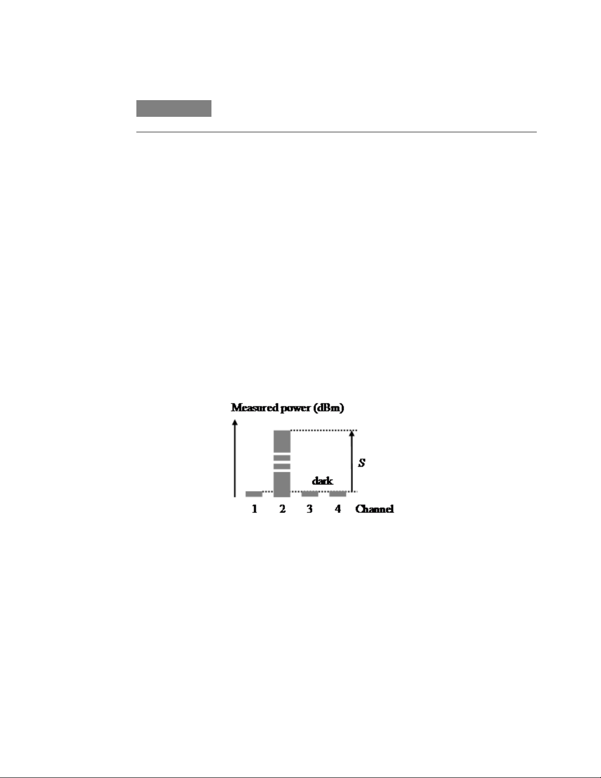
Specifications and Regulations Compliance 4
N O T E
If the tunable laser source module is rack- mounted the temperature and humidity
within the rack apply.
Polarization dependent responsivity (PDR)
Specifies the dependence of the measured power on the input state of
polarization (SOP) as ± half the difference between the highest and the
lowest measured power over all SOPs, expressed in dB.
Powers expressed in dBm.
Conditions: As specified.
Port separation (static)
Specifies the difference between the power P applied to one port and
the measured power D on any other port with no applied power (dark).
Excluding "Noise pp (dark)" (see, “Noise pp (dark)” on page 65) and
"Drift (dark)" (see, “Drift (dark)” on page 63).
Powers expressed in dBm, port separation S expressed in dB,
S = P – D
Figure 44 Port separation (static)
Conditions: Applied power level as specified.
Port separation, dynamic
Specifies the difference between step power input P
or negative slope) applied to one port and the maximum measured
power change D
applied power (dark). Excluding "Noise pp (dark)" (see, “Noise pp
(dark)” on page 65) and "Drift (dark)" (see, “Drift (dark)” on page 63).
Keysight N774x Series 67
(positive or negative) on any other port without
chng
(with positive
step
Page 69

4 Specifications and Regulations Compliance
Powers expressed in dBm, dynamic port separation SD expressed in
dB.
SD = P
Conditions: Power step height as specified (1 mW).
step
- D
chng
Power range
Specifies the range from the smallest input power that causes a
significant change of the measured (displayed) power to the highest
power for which the specifications apply if not differently stated.
Range settling time (one range step)
When changing from one power meter range to the next (one range
higher or lower), the settling time specifies the time required for the
power meter to settle into the new range. Measurements starting after
that period are within specifications.
The time starts when the instrument receives the range change
command (manual range) or when the instrument detects the
requirement for power meter range change (autorange).
Conditions: As specified.
Relative port to port uncertainty
Specifies ± half the maximum difference between the measured powers
of different ports when applying the same stimulus. Measured powers
expressed in dBm, the relative port to port uncertainty U expressed in
±dB.
68
Keysight N774x Series
Page 70
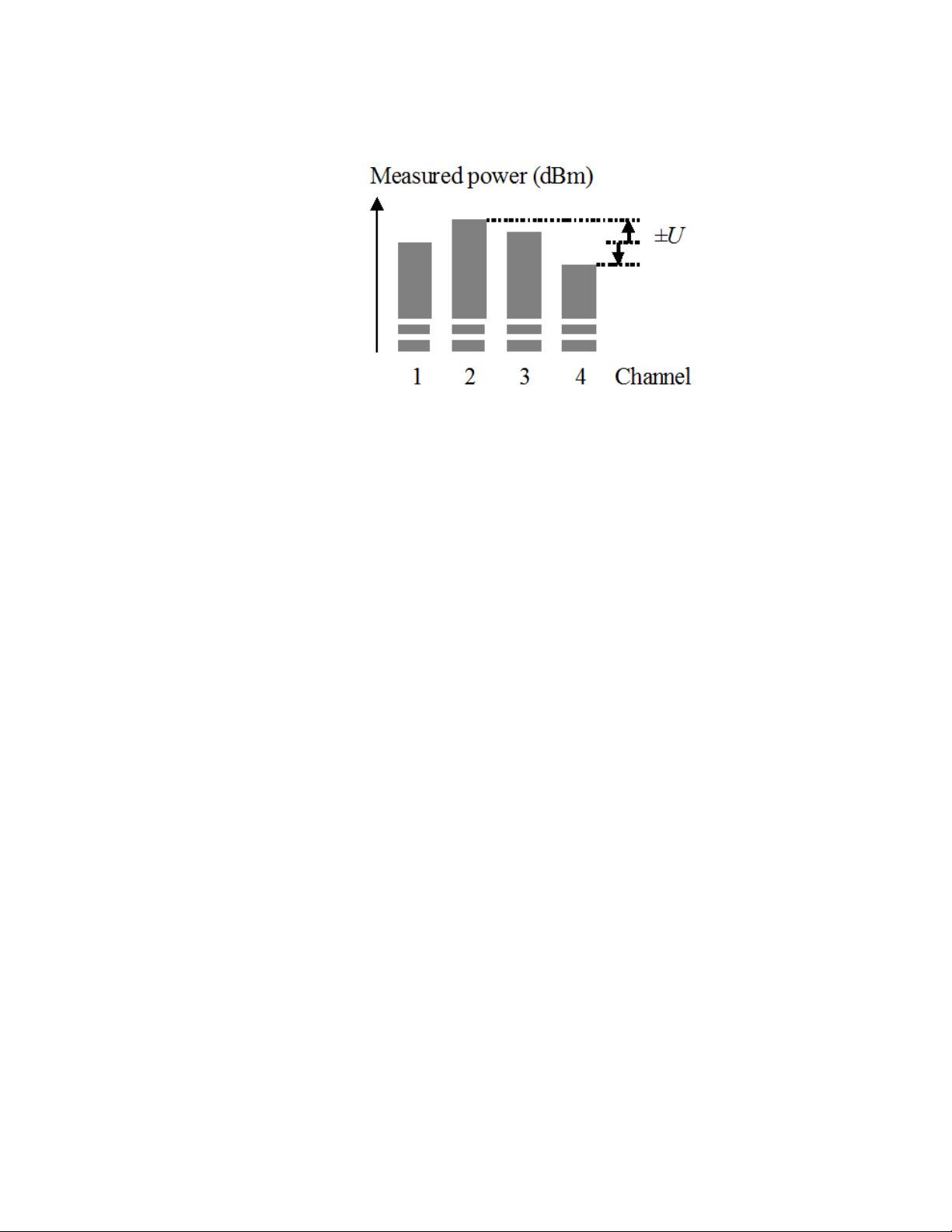
Specifications and Regulations Compliance 4
Figure 45 Relative port to port uncertainty
Conditions: As specified.
Return loss
The ratio between the incident power and the power reflected back from
the instrument into the input fiber, expressed in dB.
Conditions: As specified. (For attenuators: applicable to both ports
with fiber cables with high quality connectors in perfect optical
condition on both attenuator ports and the respective second port
terminated (zero reflectance).)
Measurement: With return loss meter and non-coherent source of
applicable wavelength.
Specification wavelength range
The wavelength range for which all specifications and characteristics
apply, if not differently stated.
Spectral ripple (power meter; due to interference)
A coherent input signal causes optical interference1 between reflective
interfaces within the power meter's optical assembly, including the end
face of a connected fiber. Optical interference causes a wavelengthdependent periodic change of the power meter's responsivity. Spectral
ripple is defined as ± half the difference between the highest and the
lowest power resulting from the periodic change.
Conditions: Constant input power, constant state of polarization (SOP).
Connector as specified. Other conditions as specified.
Keysight N774x Series 69
Page 71

4 Specifications and Regulations Compliance
Measurement: Using a laser source without spectral ripple or with
known (monitored) spectral ripple and linewidth < 100 MHz and
stepping the wavelength over the specified range. The periodic part in
the measurement result is separated by subtracting the polynomial 2nd
order fit (low frequency part).
Storage conditions
Allowed temperature and humidity range for the non-operating
instrument. Wait for acclimation to within the “Operating temperature”
before turning on the instrument.
Total uncertainty
The maximum relative difference U between measured (displayed)
power M and actual (true) power P for a specified set of operating
conditions, expressed in percent. Powers expressed in Watts. Excluding
"Noise pp (dark)" (see, “Noise pp (dark)” on page 65) and "Drift
(dark)" (see, “Drift (dark)” on page 63).
U = 100% * (M/P - 1)
Conditions: Operating conditions as specified. Other conditions as
specified.
Uncertainty at reference conditions
The maximum relative difference U between measured (displayed)
power M and actual (true) power P for the specified set of reference
conditions, including all uncertainties in the calibration chain from the
national calibration laboratory to the test meter, expressed in percent.
Powers expressed in Watts.
U = 100% * (M/P - 1)
Conditions: Reference conditions as specified.
Wavelength range
The range of wavelengths for which the power meter is calibrated, or
that can be set at the attenuator and for which the specifications apply
(if not differently stated).
70
Keysight N774x Series
Page 72

Literature
Specifications and Regulations Compliance 4
Warm-up time
Time after power-up of the acclimated instrument after which the
specifications and characteristics apply.
Fiber Optic Test and Measurement, Hewlett Packard Professional
Books, edited by Prentice Hall, ISBN 0-13-534330-5
Keysight N774x Series 71
Page 73
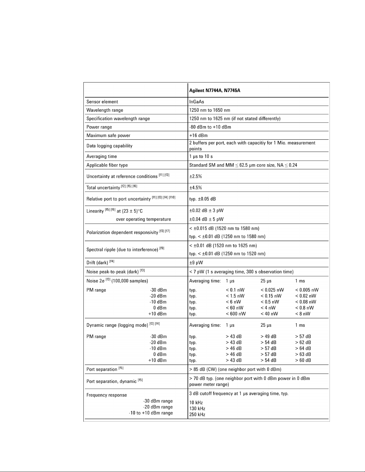
4 Specifications and Regulations Compliance
Technical Specifications - Keysight N7744A and N7745A
72
Keysight N774x Series
Page 74
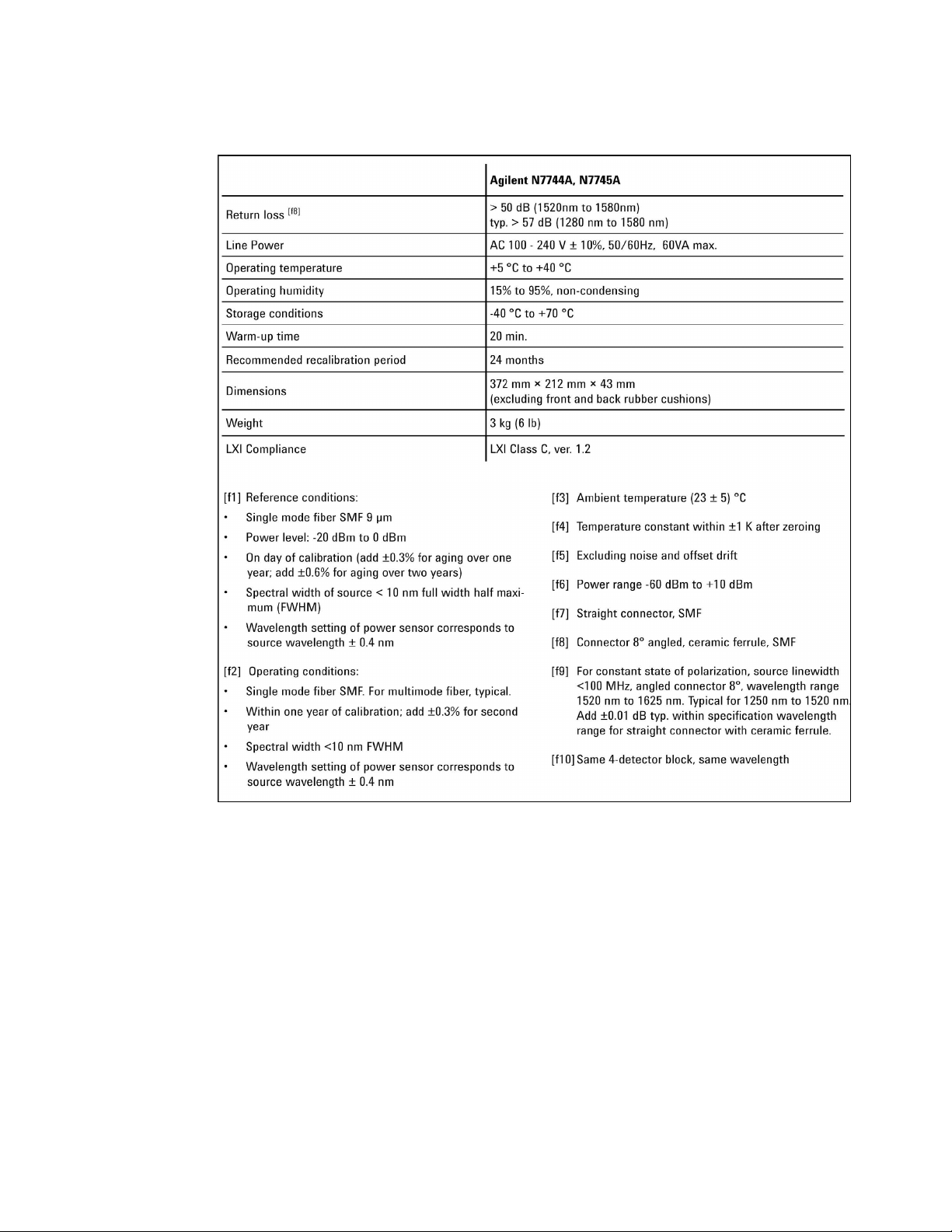
Specifications and Regulations Compliance 4
Keysight N774x Series 73
Page 75
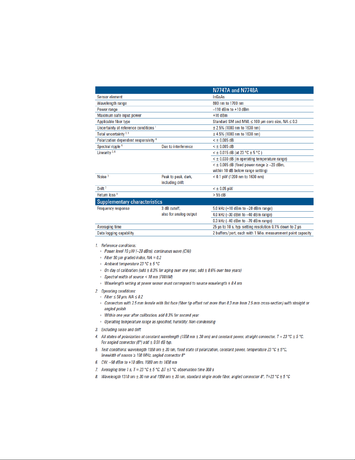
4 Specifications and Regulations Compliance
Technical Specifications - Keysight N7747A and N7748A
74
Keysight N774x Series
Page 76
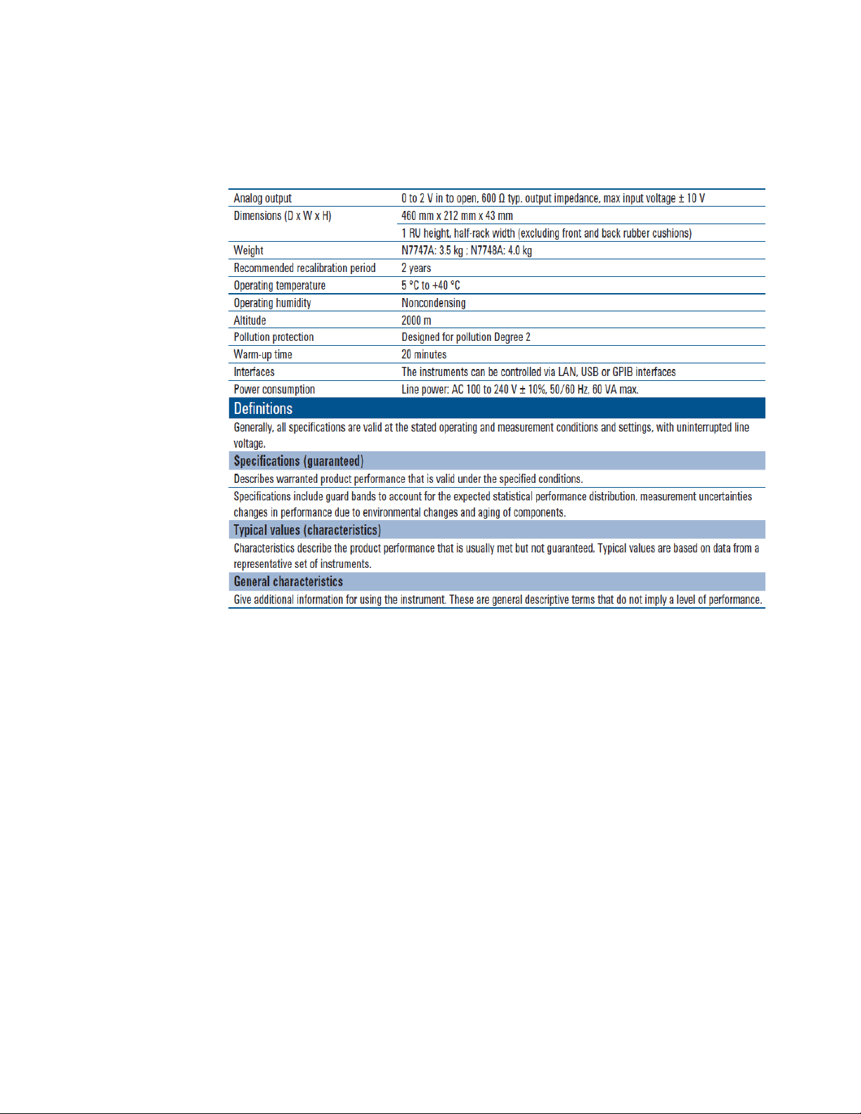
General Characteristics
Specifications and Regulations Compliance 4
Keysight N774x Series 75
Page 77
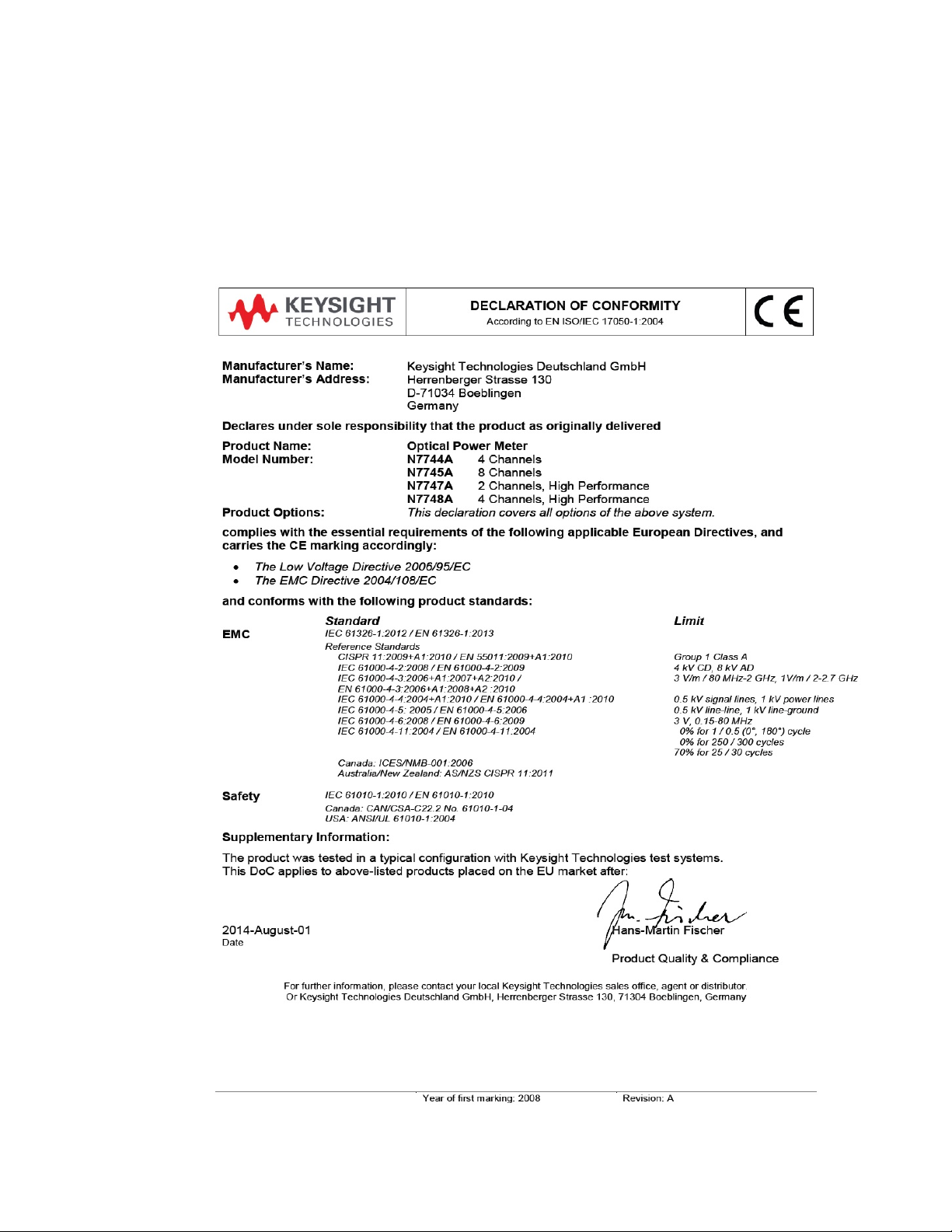
4 Specifications and Regulations Compliance
Declaration of Conformity - Keysight N7744A and N7745A
The latest version of the Declaration of Conformity can be found here
http://www.keysight.com/go/conformity
76
Keysight N774x Series
Page 78
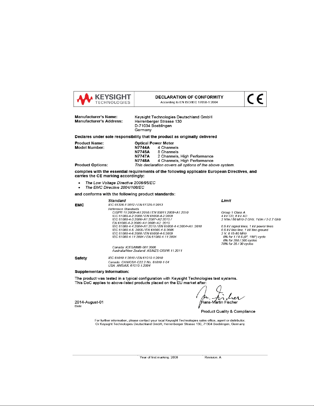
Specifications and Regulations Compliance 4
Declaration of Conformity - Keysight N7747A and N7748A
The latest version of the Declaration of Conformity can be found here
http://www.keysight.com/go/conformity
Keysight N774x Series 77
Page 79

4 Specifications and Regulations Compliance
Regulations Information
EMC Canada
These ISM devices comply with Canadian ICES-001. Ces appareils ISM
sont conformes à la norme NMB-001 du Canada.
Acoustic Noise Information Germany
ISO 7779 LpA < 70 dB(A), normal operation, operator position.
Certification
Certification
Keysight Technologies Inc. certifies that this product met its published
specifications at the time of shipment from the factory. Keysight
Technologies further certifies that its calibration measurements are
traceable to the United States National Institute of Standards and
Technology, NIST to the extent allowed by the Institutes’s calibration
facility, and to the calibration facilities of other International Standards
Organization members.
78
Keysight N774x Series
Page 80

Remove All Doubt
Remove All Doubt
Specifications and Regulations Compliance 4
Our repair and calibration services will get your equipment back to you,
performing like new, when promised. You will get full value out of your
Keysight equipment throughout its lifetime. Your equipment will be
serviced by Keysight-trained technicians using the latest factory
calibration procedures, automated repair diagnostics and genuine
parts. You will always have the utmost confidence in your
measurements.
and measurement services for your equipment, including initial startup assistance, onsite education and training, as well as design, system
integration, and project management. For more information on repair
and calibration services, go to
www.keysight.com/find/removealldoubt
Keysight offers a wide range of additional expert test
Keysight E-mail Updates
Get the latest information on the products and applications you select.
www.keysight.com/find/emailupdates
Keysight Direct
Quickly choose and use your test equipment solutions with confidence.
www.keysight.com/find/mykeysight
Keysight N774x Series 79
Page 81
4 Specifications and Regulations Compliance
Keysight Open
Keysight Open simplifies the process of connecting and programming
test systems to help engineers design, validate and manufacture
electronic products. Keysight offers open connectivity for a broad
range of
standard I/O and global support, which are combined to more easily
integrate test system development.
www.keysight.com/find/open
LXI
LXI is the LAN-based successor to GPIB, providing faster, more efficient
connectivity. Keysight is a founding member of the LXI consortium.
systemready instruments, open industry software, PC-
www.lxistandard.org
www.keysight.com
For more information on Keysight Technologies products, applications
and services, please contact your local Keysight office. The complete
list is available at:
www.keysight.com/find/contactus
80
Keysight N774x Series
Page 82

Accessories - Overview
Keysight N774x Series
User's Guide
5 Accessories
The instruments are available in various configurations for the best
possible match to the most common applications.
This chapter provides information on the available options and
accessories.
Instrument and Options - Keysight N7744A and N7745A
Table 4
N7744A, N7745A ordering options
N7744A Optical Multiport Power Meter (4
channel)
N7748A Optical Multiport Power Meter (8
channel)
includes: USB and cross-over LAN cable
Accessories
N7740FI FC Connector Adapter for Optical
Multiport Power Meter
N7740KI SC Connector Adapter for Optical
Multiport Power Meter
81
Page 83

5 Accessories
Table 4
N7744A, N7745A ordering options
N7740LI LC Connector Adapter for Optical
Multiport Power Meter
N7740MI MU Connector Adapter for Optical
Multiport Power Meter
N7740ZI Blank Zeroing Connector Adapter
for Optical Multiport Power Meter
N7740BI Bare Fibre Connector Adapter for
Optical Multiport Power Meter
81004BM Bare Fibre Holder Set for 0-400 µm
Fibres (4 each with gauge)
81009BM Bare Fibre Holder Set for 400-900
µm Fibres (4 each with gauge)
N O T E
N7744A-100 Rack Mount Kit for one or two
Multiport Power Meter Units
N7744A-100 does not mount two units of different depth.
Service and Repair
R-50C-011-3 Keysight calibration up-front
support plan 3 year coverage
R-50C-011-5 Keysight calibration up-front
support plan 5 year coverage
82
Keysight N774x Series
Page 84

Instrument and Options - Keysight N7747A and N7748A
Table 6
N7747A, N7748A ordering options
N7747A Optical High Performance Power
Meter (2 channel)
N7748A Optical High Performance Power
Meter (4 channel)
includes: USB and cross-over LAN cable
Accessories
81000FI FC Connector Interface
Accessories 5
81000KI SC Connector Interface
81000PI E-2000 Connector Interface
(sensor only)
81000SI DIN 47256/4108 Connector
Interface
81000VI ST Connector Interface
81002LI LC Connector Interface
81002MI MU Connector Interface
81000BI Bare Fiber Interface Kit
N7744A-100 Rack Mount Kit for one or two
Optical High Performance Power
Meter Units
Keysight N774x Series 83
Page 85

5 Accessories
N O T E
The sensors are optimized for use with 2.5 mm ferrule connectors, for which the
positioning is most repeatable. For use with LC or MU connectors with 1.25 mm
ferrules, only the 81002LI for LC or 81002MI for MU should be used. The 81000LI
and 81000MI should not be used. But positioning uncertainty with the 81002LI or
81002MI can still degrade the absolute power uncertainty by up to +/- 1 dB,
considering worst-case offsets within the tolerances of the connectors and
adapters. For LC and MU connectors, use of the 8162x optical power heads or the
N7744A and N7745A power meters with corresponding adapters is recommended
for highest accuracy.
Ferrules with conical or raised-end faces also add positioning uncertainty and are
not recommended for use with the N7747A or N7748A.
Service and Repair
R-50C-011-3 Keysight calibration up-front
support plan 3 year coverage
R-50C-011-5 Keysight calibration up-front
support plan 5 year coverage
Cables
GPIB Cable, 10833A, 1 m (3.3 feet)
•
GPIB Cable, 10833B, 2 m (6.6 feet)
•
GPIB Cable, 10833C, 4 m (13.2 feet)
•
GPIB Cable, 10833D, 0.5 m (1.6 feet)
•
GPIB Adapter, 10834A, 2.3 cm extender. Use this adapter if there is
•
no space to connect your GPIB cable directly to a GPIB interface.
USB Cable, 8121-1243, 2 m (6.6 feet)
•
Cross-over LAN cable, 5061-0701, 2.1 m (7 feet)
•
84 Keysight N774x Series
Page 86

Keysight N774x Series
User's Guide
6 Maintenance and Troubleshooting
Maintenance and Troubleshooting - Overview
This section provides detailed information on:
Cleaning Instructions
•
Firmware Upgrades
•
Error Messages
•
Data Sanitation
•
Cleaning Instructions
Cleaning Instructions
The following Cleaning Instructions contain some general safety
precautions, which must be observed during all phases of cleaning.
Consult your specific optical device manuals or guides for full
information on safety matters.
Please try, whenever possible, to use physically contacting connectors,
and dry connections. Clean the connectors, interfaces, and bushings
carefully after use.
If you are unsure of the correct cleaning procedure for your optical
device, we recommend that you first try cleaning a dummy or test
device.
Keysight Technologies assume no liability for the customer’s failure
to comply with these requirements.
85
Page 87

6 Maintenance and Troubleshooting
Cleaning Instructions for this Instrument
Safety Precautions
The Cleaning Instructions apply to a number of different types of
Optical Equipment. Most relevant for this instrument is the section
“How to clean connector adapters” on page 95 for cleaning the quad-
adapters, and “How to clean optical glass plates” on page 96 for
cleaning the front of the instrument.
Please follow the following safety rules:
Do not remove instrument covers when operating.
•
Ensure that the instrument is switched off throughout the cleaning
•
procedures.
Use of controls or adjustments or performance of procedures other
•
than those specified may result in hazardous radiation exposure.
Make sure that you disable all sources when you are cleaning any
•
optical interfaces.
Under no circumstances look into the end of an optical device
•
attached to optical outputs when the device is operational. The laser
radiation is not visible to the human eye, but it can seriously damage
your eyesight.
To prevent electrical shock, disconnect the instrument from the
•
mains before cleaning. Use a dry cloth, or one slightly dampened with
water, to clean the external case parts. Do not attempt to clean
internally.
Do not install parts or perform any unauthorized modification to
•
optical devices.
Refer servicing only to qualified and authorized personnel.
•
Why is it important to clean optical devices?
In transmission links optical fiber cores are about 9 µm (0.00035") in
diameter. Dust and other particles, however, can range from tenths to
hundredths of microns in diameter. Their comparative size means that
they can cover a part of the end of a fiber core, and as a result will reduce
the performance of your system.
86 Keysight N774x Series
Page 88

Furthermore, the power density may burn dust into the fiber and cause
additional damage (for example, 0 dBm optical power in a single mode
fiber causes a power density of approximately 16 million W/m2). If this
happens, measurements become inaccurate and non-repeatable.
Cleaning is, therefore, an essential yet difficult task. Unfortunately,
when comparing most published cleaning recommendations, you will
discover that they contain several inconsistencies. In this section, we
want to suggest ways to help you clean your various optical devices, and
thus significantly improve the accuracy and repeatability of your
lightwave measurements.
What do I need for proper cleaning?
Some Standard Cleaning Equipment is necessary for cleaning your
instrument. For certain cleaning procedures, you may also require
certain Additional Cleaning Equipment.
Maintenance and Troubleshooting 6
Standard Cleaning Equipment
Before you can start your cleaning procedure you need the following
standard equipment:
Dust and shutter caps
•
Isopropyl alcohol
•
Cotton swabs
•
Soft tissues
•
Pipe cleaner
•
Compressed air
•
Dust and shutter caps
All of Keysight Technologies’ lightwave instruments are delivered
with either laser shutter caps or dust caps on the lightwave adapter.
Any
cables come with covers to protect the cable ends from damage
or contamination.
We suggest these protected coverings should be kept on the equipment
at all times, except when your optical device is in use. Be careful when
replacing dust caps after use. Do not press the bottom of the cap onto
the fiber too hard, as any dust in the cap can scratch or pollute your
fiber surface.
Keysight N774x Series 87
Page 89

6 Maintenance and Troubleshooting
If you need further dust caps, please contact your nearest
Keysight Technologies sales office.
Isopropyl alcohol
This solvent is usually available from any local pharmaceutical supplier
or chemist's shop.
If you use isopropyl alcohol to clean your optical device, do not
immediately dry the surface with compressed air (except when you are
cleaning very sensitive optical devices). This is because the dust and the
dirt is solved and will leave behind filmy deposits after the alcohol is
evaporated. You should therefore first remove the alcohol and the dust
with a soft tissue, and then use compressed air to blow away any
remaining filaments.
If possible avoid using denatured alcohol containing additives. Instead,
apply alcohol used for medical purposes. Never try to drink this alcohol,
as it may seriously damage to your health.
Do not use any other solvents, as some may damage plastic materials
and claddings. Acetone, for example, will dissolve the epoxy used with
fiber optic connectors. To avoid damage, only use isopropyl alcohol.
Cotton swabs
We recommend that you use swabs such as Q-tips or other cotton swabs
normally available from local distributors of medical and hygiene
products (for example, a supermarket or a chemist's shop). You may be
able to obtain various sizes of swab. If this is the case, select the smallest
size for your smallest devices.
Ensure that you use natural cotton swabs. Foam swabs will often leave
behind filmy deposits after cleaning.
Use care when cleaning, and avoid pressing too hard onto your optical
device with the swab. Too much pressure may scratch the surface, and
could cause your device to become misaligned. It is advisable to rub
gently over the surface using only a small circular movement.
Swabs should be used straight out of the packet, and never used twice.
This is because dust and dirt in the atmosphere, or from a first cleaning,
may collect on your swab and scratch the surface of your optical device.
Soft tissues
These are available from most stores and distributors of medical and
hygiene products such as supermarkets or chemists' shops.
88
Keysight N774x Series
Page 90

Maintenance and Troubleshooting 6
We recommend that you do not use normal cotton tissues, but multilayered soft tissues made from non-recycled cellulose. Cellulose tissues
are very absorbent and softer. Consequently, they will not scratch the
surface of your device over time.
Use care when cleaning, and avoid pressing on your optical device with
the tissue. Pressing too hard may lead to scratches on the surface or
misalignment of your device. Just rub gently over the surface using a
small circular movement.
Use only clean, fresh soft tissues and never apply them twice. Any dust
and dirt from the air which collects on your tissue, or which has
gathered after initial cleaning, may scratch and pollute your optical
device.
Pipe cleaner
Pipe cleaners can be purchased from tobacconists, and come in various
shapes and sizes. The most suitable one to select for cleaning purposes
has soft bristles, which will not produces scratches.
There are many different kinds of pipe cleaner available from tobacco
shops.
The best way to use a pipe cleaner is to push it in and out of the device
opening (for example, when cleaning an interface). While you are
cleaning, you should slowly rotate the pipe cleaner.
Only use pipe cleaners on connector interfaces or on feed through
adapters. Do not use them on optical head adapters, as the center of a
pipe cleaner is hard metal and can damage the bottom of the adapter.
Your pipe cleaner should be new when you use it. If it has collected any
dust or dirt, this can scratch or contaminate your device.
The tip and center of the pipe cleaner are made of metal. Avoid
accidentally pressing these metal parts against the inside of the device,
as this can cause scratches.
Compressed air
Compressed air can be purchased from any laboratory supplier.
It is essential that your compressed air is free of dust, water and oil.
Only use clean, dry air. If not, this can lead to filmy deposits or scratches
on the surface of your connector. This will reduce the performance of
your transmission system.
When spraying compressed air, hold the can upright. If the can is held
at a slant, propellant could escape and dirty your optical device. First
spray into the air, as the initial stream of compressed air could contain
Keysight N774x Series 89
Page 91

6 Maintenance and Troubleshooting
some condensation or propellant. Such condensation leaves behind a
filmy deposit.
Please be friendly to your environment and use a CFC-free aerosol.
Additional Cleaning Equipment
Some Cleaning Procedures need the following equipment, which is not
required to clean each instrument:
Microscope with a magnification range about 50X up to 300X
•
Ultrasonic bath
•
Warm water and liquid soap
•
Premoistened cleaning wipes
•
Polymer film
•
Infrared Sensor Card
•
Microscope with a magnification range about 50X up to 300X
A microscope can be found in most photography stores, or can be
obtained through or specialist mail order companies. Special fiberscopes are available from suppliers of splicing equipment.
Ideally, the light source on your microscope should be very flexible. This
will allow you to examine your device closely and from different angles.
A microscope helps you to estimate the type and degree of dirt on your
device. You can use a microscope to choose an appropriate cleaning
method, and then to examine the results. You can also use your
microscope to judge whether your optical device (such as a connector)
is severely scratched and is, therefore, causing inaccurate
measurements.
Ultrasonic bath
Ultrasonic baths are also available from photography or laboratory
suppliers or specialist mail order companies.
An ultrasonic bath will gently remove fat and other stubborn dirt from
your optical devices. This helps increase the life span of the optical
devices.
Only use isopropyl alcohol in your ultrasonic bath, as other solvents
may damage.
90
Keysight N774x Series
Page 92

Maintenance and Troubleshooting 6
Warm water and liquid soap
Only use water if you are sure that there is no other way of cleaning
your optical device without corrosion or damage. Do not use hot water,
as this may cause mechanical stress, which can damage your optical
device.
Ensure that your liquid soap has no abrasive properties or perfume in
it. You should also avoid normal washing-up liquid, as it can cover your
device in an iridescent film after it has been air-dried.
Some lenses and mirrors also have a special coating, which may be
sensitive to mechanical stress, or to fat and liquids. For this reason we
recommend you do not touch them.
If you are not sure how sensitive your device is to cleaning, please
contact the manufacturer or your sales distributor.
Premoistened cleaning wipes
Use pre-moistened cleaning wipes as described in each individual
cleaning procedure. Cleaning wipes may be used in every instance
where a moistened soft tissue or cotton swab is applied.
Polymer film
Polymer film is available from laboratory suppliers or specialist mail
order companies.
Using polymer film is a gentle method of cleaning extremely sensitive
devices, such as reference reflectors and mirrors.
Infrared Sensor Card
Infrared sensor cards are available from laboratory suppliers or
specialist mail order companies.
With this card you are able to control the shape of laser light emitted.
The invisible laser beam is projected onto the sensor card, then becomes
visible to the normal eye as a round spot.
Take care never to look into the end of a fiber or any other optical
component, when they are in use. This is because the laser can seriously
damage your eyes.
Keysight N774x Series 91
Page 93

6 Maintenance and Troubleshooting
Preserving Connectors
Listed below are some hints on how best to keep your connectors in the
best possible condition.
Making Connections
Before you make any connection you must ensure that all cables and
connectors are clean. If they are dirty, use the appropriate cleaning
procedure.
When inserting the ferrule of a patchcord into a connector or an
adapter, make sure that the fiber end does not touch the outside of the
mating connector or adapter. Otherwise you will rub the fiber end
against an unsuitable surface, producing scratches and dirt deposits on
the surface of your fiber.
Dust Caps and Shutter Caps
Be careful when replacing dust caps after use. Do not press the bottom
of the cap onto the fiber as any dust in the cap can scratch or dirty your
fiber surface.
When you have finished cleaning, put the dust cap back on, or close the
shutter cap if the equipment is not going to be used immediately.
Keep the caps on the equipment always when it is not in use.
All of Keysight Technologies’ lightwave instruments and accessories
are shipped with either laser shutter caps or dust caps. If you need
additional or replacement dust caps, contact your nearest Keysight
Technologies Sales/Service Office.
Immersion Oil and Other Index Matching Compounds
Where it is possible, do not use immersion oil or other index matching
compounds with your device. They are liable to impair and dirty the
surface of the device. In addition, the characteristics of your device can
be changed and your measurement results affected.
Cleaning Instrument Housings
Use a dry and very soft cotton tissue to clean the instrument housing
and the keypad. Do not open the instruments as there is a danger of
electric shock, or electrostatic discharge. Opening the instrument can
92 Keysight N774x Series
Page 94

cause damage to sensitive components, and in addition your warranty
will be voided.
Never open the instruments as they can be damaged. Opening the
instruments puts you in danger of receiving an electrical shock from
your device, and renders your warranty void.
Which Cleaning Procedure should I use?
Light dirt
If you just want to clean away light dirt, observe the following procedure
for all devices:
Use compressed air to blow away large particles.
1
Clean the device with a dry cotton swab.
2
Use compressed air to blow away any remaining filament left by the
3
swab.
Maintenance and Troubleshooting 6
Heavy dirt
If the above procedure is not enough to clean your instrument, follow
one of the procedures below. Please consult “Cleaning Instructions for
this Instrument” on page 86 for the procedure relevant for this
instrument.
If you are unsure of how sensitive your device is to cleaning, please
contact the manufacturer or your sales distributor
How to clean connectors
Cleaning connectors is difficult as the core diameter of a single-mode
fiber is only about 9 µm. This generally means you cannot see streaks
or scratches on the surface. To be certain of the condition of the surface
of your connector and to check it after cleaning, you need a microscope.
In the case of scratches, or of dust that has been burnt onto the surface
of the connector, you may have no option but to polish the connector.
This depends on the degree of dirtiness, or the depth of the scratches.
This is a difficult procedure and should only be performed by skilled
personal, and as a last resort as it wears out your connector.
Keysight N774x Series 93
Page 95

6 Maintenance and Troubleshooting
W A R N I N G
Never look into the end of an optical cable that is connected to an active source.
To assess the projection of the emitted light beam you can use an infrared sensor
card. Hold the card approximately 5 cm from the output of the connector. The
invisible emitted light is project onto the card and becomes visible as a small
circular spot.
Preferred Procedure
Use the following procedure on most occasions.
Clean the connector by rubbing a new, dry cotton-swab over the
1
surface using a small circular movement.
Blow away any remaining lint with compressed air.
2
Procedure for Stubborn Dirt
Use this procedure particularly when there is greasy dirt on the
connector:
Moisten a new cotton-swab with isopropyl alcohol.
1
Clean the connector by rubbing the cotton-swab over the surface
2
using a small circular movement.
Take a new, dry soft-tissue and remove the alcohol, dissolved
3
sediment and dust, by rubbing gently over the surface using a small
circular movement.
Blow away any remaining lint with compressed air.
4
An Alternative Procedure
A better, more gentle, but more expensive cleaning procedure is to use
an ultrasonic bath with isopropyl alcohol.
Hold the tip of the connector in the bath for at least three minutes.
1
Take a new, dry soft-tissue and remove the alcohol, dissolved
2
sediment and dust, by rubbing gently over the surface using a small
circular movement.
Blow away any remaining lint with compressed air.
3
94
Keysight N774x Series
Page 96

How to clean connector adapters
Preferred Procedure
Use the following procedure on most occasions.
Clean the adapter by rubbing a new, dry cotton-swab over the surface
1
using a small circular movement.
Blow away any remaining lint with compressed air.
2
Procedure for Stubborn Dirt
Use this procedure particularly when there is greasy dirt on the adapter:
Moisten a new cotton-swab with isopropyl alcohol.
1
Clean the adapter by rubbing the cotton-swab over the surface using
2
a small circular movement.
Take a new, dry soft-tissue and remove the alcohol, dissolved
3
sediment and dust, by rubbing gently over the surface using a small
circular movement.
Maintenance and Troubleshooting 6
Blow away any remaining lint with compressed air.
4
How to clean bare fiber adapters
Bare fiber adapters are difficult to clean.
Protect from dust unless they are in use.
C A U T I O N
Never use any kind of solvent when cleaning a bare fiber adapter as solvents can
damage the foam inside some adapters.
They can deposit dissolved dirt in the groove, which can then dirty the surface of
an inserted fiber.
Preferred Procedure
Use the following procedure on most occasions.
Blow away any dust or dirt with compressed air.
1
Keysight N774x Series 95
Page 97

6 Maintenance and Troubleshooting
How to clean optical glass plates
The multiport power meter has an optical glass plate to protect the
sensor. This has a special coating that is sensitive to solvents, grease,
liquid and mechanical abrasion. Take extra care when cleaning this
plate.
Preferred Procedure
Use the following procedure on most occasions.
Clean the plate by rubbing a new, dry cotton-swab over the surface
1
using a small circular movement.
Blow away any remaining lint with compressed air.
2
Procedure for Stubborn Dirt
Use this procedure particularly when there is greasy dirt on the plate:
Moisten a new cotton-swab with isopropyl alcohol.
1
Clean the plate by rubbing the cotton-swab over the surface using a
2
small circular movement.
Using a new, dry cotton-swab remove the alcohol, any dissolved
3
sediment and dust.
Blow away any remaining lint with compressed air.
4
Additional Cleaning Information
The following cleaning procedures may be used with other optical
equipment:
How to clean bare fiber ends
•
How to clean bare fiber ends
Bare fiber ends are often used for splices or, together with other optical
components, to create a parallel beam. The end of a fiber can often be
scratched. You make a new cleave. To do this:
Strip off the cladding.
1
Take a new soft-tissue and moisten it with isopropyl alcohol.
2
Carefully clean the bare fiber with this tissue.
3
96 Keysight N774x Series
Page 98

Make your cleave and immediately insert the fiber into your bare
4
fiber adapter in order to protect the surface from dirt.
Other Cleaning Hints
Selecting the correct cleaning method is an important element in
maintaining your equipment and saving you time and money. This
Appendix highlights the main cleaning methods, but cannot address
every individual circumstance.
This section contain some additional hints which we hope will help you
further. For further information, please contact your local Keysight
Technologies representative.
Making the connection
Before you make any connection you must ensure that all lightwave
cables and connectors are clean. If not, then use appropriate the
cleaning methods.
Maintenance and Troubleshooting 6
When you insert the ferrule of a patchcord into a connector or an
adapter, ensure that the fiber end does not touch the outside of the
mating connector or adapter. Otherwise, the fiber end will rub up
against something which could scratch it and leave deposits.
Lens cleaning papers
Note that some special lens cleaning papers are not suitable for cleaning
optical devices like connectors, interfaces, lenses, mirrors and so on. To
be absolutely certain that a cleaning paper is applicable, please ask the
salesperson or the manufacturer.
Firmware Upgrades
Updated versions of the firmware for your instrument may be released
from time to time. These will then be available from the Keysight web
page (www.keysight.com/find/octfirmware) and will include the
update application and instructions.
Keysight N774x Series 97
Page 99

6 Maintenance and Troubleshooting
Error Messages
SYST:ERR?
Hardware Error
syst:err?
The
(refer to the Programming Guide for details).
Each error has an error code and a short description of the error,
separated by comma. Please note that the error codes are returned as
signed integer numbers in a range from -32768 to +32767 (INT16).
Negative error numbers are defined by the SCPI standard, positive error
numbers are device dependent.
If the Red "Error" LED on the front panel is illuminated it may indicate
a hardware error. The defective channel(s) is then deactivated and is
no longer in specification. The unit should be sent for repair. The
command
channel, as detailed in the Programming Guide.
Example:
Indicates a hardware error on channel 2 of the N7747A or N7748A.
command returns the next error from the error queue
Stat[n]:ques:cond?
Stat2:ques:cond? -> 1
can be used to identify the defective
Data Sanitation
Memory Inventory
98
The instruments have the following memory size:
EEPROM 2 Mb for N7744A and N7747A. 3 Mb for N7745A and N7748A.
This memory does not contain any customer data.
Flash ROM 16 MB. This memory can contain calibration data, and so
on, as well as user parameter settings, zeroing data and logged
information (the log contains limited operational information).
Keysight N774x Series
Page 100

DRAM 128 MB volatile working memory. This contains data for
current and recent calibrating and measuring.
Clearing User Data
Clearing the DRAM
All data in the DRAM is cleared by powering the instrument off.
Clearing the Flash ROM
The user data can be cleared from the Flash ROM by:
1
Maintenance and Troubleshooting 6
Reset the instrument to factory default.
Send the command:
a
SYSTem:PRESet
OR
Press the LAN Reset button on the front panel briefly (<1 s).
b
Clear the instrument log.
2
Send the special command
a
DIAG:SYST:FLAS:LOGF:ERAS
The contents of the log can be checked with the query READ:LOGF?.
Clear the Ethernet settings
3
Connect to the instrument by some means other than the LAN,
a
using VISA Assistant (for example over USB). Send the command:
SYSTem:COMMunicate:ETHernet:RESet
OR
With the instrument connected over the LAN (the LAN LED is
b
green), press and hold the LAN Reset button for more than 3s.
In either case, the instrument reboots.
Keysight N774x Series 99
 Loading...