

Page 1
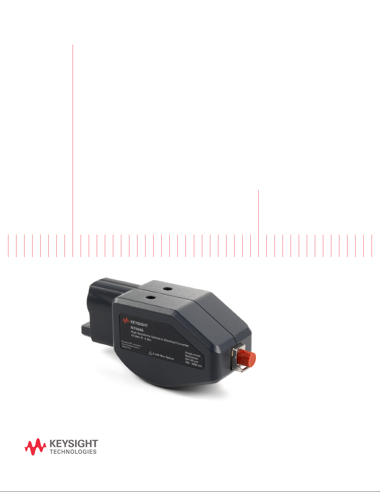
Keysight N7004A 33 GHz
Optical-to-Electrical
Converter
User Guide
Page 2

Notices
CAUTION
WARNING
© Keysight Technologies 2016, 2019
No part of this manual may be reproduced in
any form or by any means (including electronic storage and retrieval or translation
into a foreign language) without prior agreement and written consent from Keysight
Technologies as governed by United States
and international copyright laws.
Manual Part Number
N7004-92000
Edition
Second Edition, April 2019
Available in electronic format only
Published in USA
Published by:
Keysight Technologies, Inc.
1900 Garden of the Gods Road
Colorado Springs, CO 80907 USA
Warranty
THE MATERIAL CONTAINED IN THIS
DOCUMENT IS PROVIDED "AS IS," AND IS
SUBJECT TO BEING CHANGED, WITHOUT
NOTICE, IN FUTURE EDITIONS. FURTHER,
TO THE MAXIMUM EXTENT PERMITTED BY
APPLICABLE LAW, KEYSIGHT DISCLAIMS
ALL WARRANTIES, EITHER EXPRESS OR
IMPLIED WITH REGARD TO THIS MANUAL
AND ANY INFORMATION CONTAINED
HEREIN, INCLUDING BUT NOT LIMITED TO
THE IMPLIED WARRANTIES OF
MERCHANTABILITY AND FITNESS FOR A
PARTICULAR PURPOSE. KEYSIGHT SHALL
NOT BE LIABLE FOR ERRORS OR FOR
INCIDENTAL OR CONSEQUENTIAL
DAMAGES IN CONNECTION WITH THE
FURNISHING, USE, OR PERFORMANCE OF
THIS DOCUMENT OR ANY INFORMATION
CONTAINED HEREIN. SHOULD KEYSIGHT
AND THE USER HAVE A SEPARATE WRITTEN
AGREEMENT WITH WARRANTY TERMS
COVERING THE MATERIAL IN THIS
DOCUMENT THAT CONFLICT WITH THESE
TERMS, THE WARRANTY TERMS IN THE
SEPARATE AGREEMENT WILL CONTROL.
Technology Licenses
The hardware and/or software described in
this document are furnished under a license
and may be used or copied only in accordance with the terms of such license.
U.S. Government Rights
The Software is "commercial computer software," as defined by Federal Acquisition
Regulation ("FAR") 2.101. Pursuant to FAR
12.212 and 27.405-3 and Department of
Defense FAR Supplement ("DFARS")
227.7202, the U.S. government acquires
commercial computer software under the
same terms by which the software is customarily provided to the public. Accordingly,
Keysight provides the Software to U.S. government customers under its standard commercial license, which is embodied in its
End User License Agreement (EULA), a copy
of which can be found at http://www.key-
sight.com/find/sweula. The license set
forth in the EULA represents the exclusive
authority by which the U.S. government may
use, modify, distribute, or disclose the Software. The EULA and the license set forth
therein, does not require or permit, among
other things, that Keysight: (1) Furnish technical information related to commercial
computer software or commercial computer
software documentation that is not customarily provided to the public; or (2) Relinquish
to, or otherwise provide, the government
rights in excess of these rights customarily
provided to the public to use, modify, reproduce, release, perform, display, or disclose
commercial computer software or commercial computer software documentation. No
additional government requirements beyond
those set forth in the EULA shall apply,
except to the extent that those terms, rights,
or licenses are explicitly required from all
providers of commercial computer software
pursuant to the FAR and the DFARS and are
set forth specifically in writing elsewhere in
the EULA. Keysight shall be under no obligation to update, revise or otherwise modify
the Software. With respect to any technical
data as defined by FAR 2.101, pursuant to
FAR 12.211 and 27.404.2 and DFARS
227.7102, the U.S. government acquires no
greater than Limited Rights as defined in
FAR 27.401 or DFAR 227.7103-5 (c), as
applicable in any technical data. 52.227-14
(June 1987) or DFAR 252.227-7015 (b)(2)
(November 1995), as applicable in any technical data.
Safety Notices
A CAUTION notice denotes a hazard. It
calls attention to an operating procedure, practice, or the like that, if not
correctly performed or adhered to,
could result in damage to the product
or loss of important data. Do not proceed beyond a CAUTION notice until
the indicated conditions are fully
understood and met.
A WARNING notice denotes a hazard.
It calls attention to an operating procedure, practice, or the like that, if not
correctly performed or adhered to,
could result in personal injury or
death. Do not proceed beyond a
WARNING notice until the indicated
conditions are fully understood and
met.
2 N7004A 33GHz Optical-to-Electrical-Converter User Guide
Page 3

Contents
1 N7004A - Overview
2 Setting up the N7004A O/E Converter
Introduction 6
Usage 7
Features 8
Specifications and Characteristics 9
Dimensions 10
Prerequisites 12
Oscilloscope Bandwidth Requirements 12
Step 1 - Clean the Fiber-Optic Connectors 14
To visually inspect the fiber-ends 14
To clean the fiber-end of the N7004A fiber-optic connector 15
To clean the fiber-end of the mating fiber-optic cable or patch cable 16
Step 2 - Connect the N7004A Output to a Compatible Keysight Oscilloscope 18
Step 3 - Connect a Fiber-optic Cable to the N7004A Optical Input Connector 19
Selection of the Fiber-optic Cable 19
Guidelines for Making the Connection 19
Aligning the Keying Features while Making the Connection 19
Step 4- Configure the N7004A Setup on the Infiniium Software 21
Selecting the Wavelength 21
Adjusting Conversion Gain for a User-defined Wavelength 22
Configuring the Bandwidth Limits for the Oscilloscope and its Channel 24
Adjusting the Vertical Settings for the Oscilloscope Channel 25
Adding and Configuring Optical Measurements 25
Step 5 - Perform Dark Calibration 28
What is Dark Calibration 28
When to perform Dark Calibration 28
To perform dark calibration 28
Reasons for the Failure of the Dark Calibration 30
3 Making Optical Measurements and Analyzing Results
N7004A Optical Measurements 34
Optical Measurement Results 34
N7004A 33GHz Optical-to-Electrical-Converter User Guide 3
Page 4

Contents
Performing Eye Mask Testing 37
Types of Masks Supported with N7004A 37
Mask Margins 37
4 Remotely Controlling the N7004A Measurement Setup
Sample Remote Control Setup of N7004A 40
SCPI Commands for Controlling the N7004A Setup 41
:MEASure:OPOWer 42
:MEASure:CGRade:OLEVel 43
:MEASure:CGRade:ZLEVel 44
:MEASure:OMAMplitude 45
:MEASure:ERATio 46
5 Performance Verification for N7004A
Test S t rategy 48
Test I n terval 48
Test Equipment 48
Test Procedure 49
6 Calibration Strategy
7 Troubleshooting
Troubleshooting Flowchart 56
8 Returning the N7004A for Repair or Service
Contacting Keysight Technologies 57
9 Safety and Regulatory Information
Instrument Markings 60
4 N7004A 33GHz Optical-to-Electrical-Converter User Guide
Page 5

N7004A 33GHz Optical-to-Electrical-Converter
User Guide
1 N7004A - Overview
Introduction / 6
Usage / 7
Features / 8
Specifications and Characteristics / 9
Dimensions / 10
This chapter introduces the N7004A O/E Converter and lists its features, usage, characteristics and
specifications.
Page 6
1 Overview
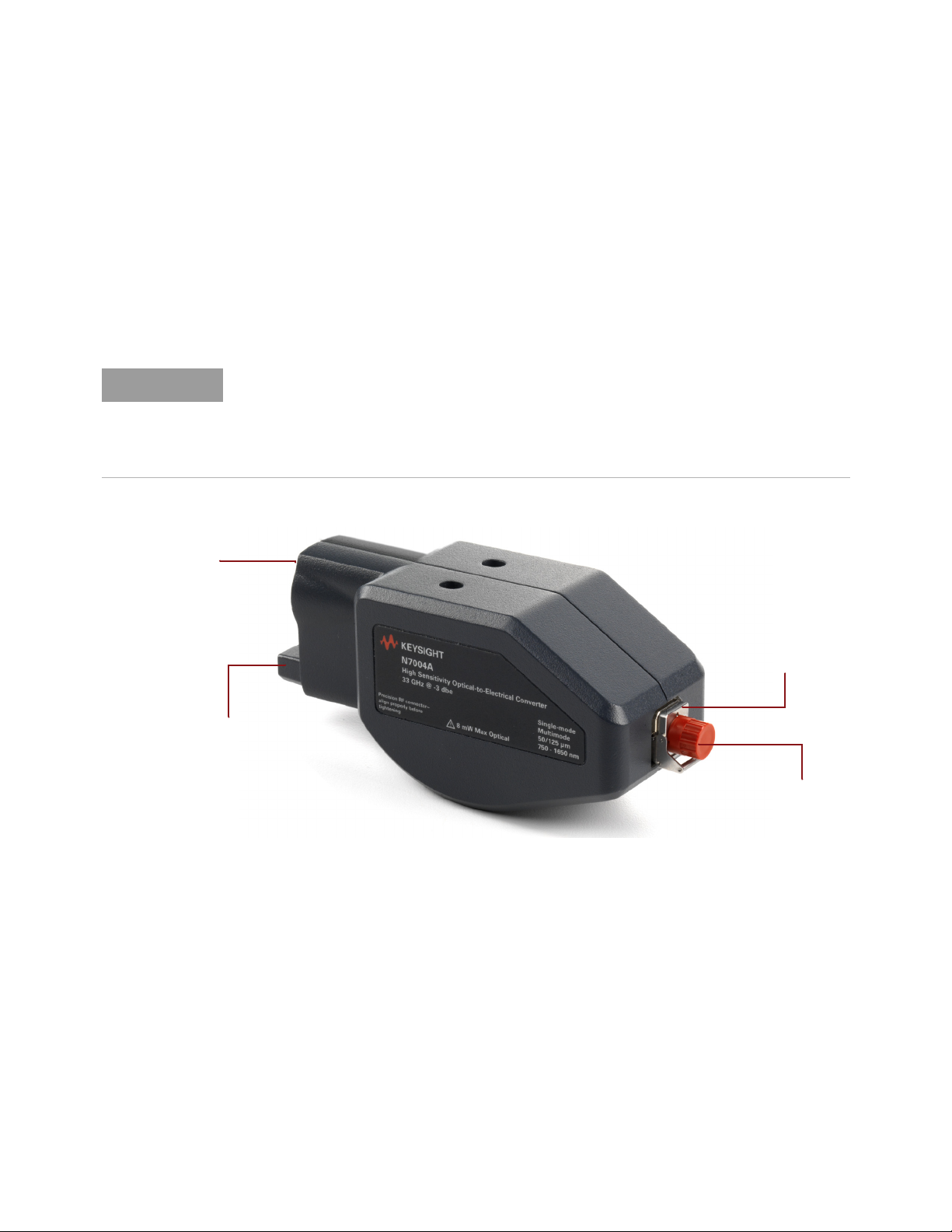
NOTE
AutoProbe II
Connector
Fiber-optic
Receptacle with
FC/PC Input
Connector
Plastic cap for the FC/PC
Input Connector
Connection for probe
power and
auto-configuration
Introduction
The N7004A 33 GHz optical-to-electrical converter directly converts optical signals into electrical
signals for convenient analysis on a compatible Infiniium real-time oscilloscope.
The N7004A is a high-sensitivity photodetector module that comes with an FC/PC input connector to
receive optical telecom or datacom signals from an optical source/transmitter through a
single-mode or a multimode fiber.
The electrical output of the N7004A is provided for analysis to an Infiniium real-time oscilloscope
through the AutoProbe II connector that connects the N7004A to the oscilloscope’s channel input.
The N7004A O/E Converter is designed for use with oscilloscopes that have AutoProbe II
interface channel inputs.
In addition to providing connectivity between the oscilloscope and N7004A, this interface also
provides power to the N7004A as well as ensures the auto-configuration of probe type and
attenuation settings when you connect the N7004A to the oscilloscope.
6 N7004A 33GHz Optical-to-Electrical-Converter User Guide
Figure 1 N7004A Optical-to-Electrical Converter - Components
Page 7

Usage
Overview 1
The following points highlight the broad usage scenarios of N7004A as an optical measurement
solution:
• To measure optical telecom or datacom signals up to 28 Gbps data rates.
• To view the raw (unfiltered) response of the optical source/transmitter under test.
• To take industry-standard optical measurements on the optical source/transmitter under test.
The N7004A supports 4th Order Bessel Thomson filter to help you accomplish this.
• To troubleshoot and perform characterization for the optical source(s) used in your optical
system.
• To test system boards with an embedded optical transceiver in scenarios where there is no clock
signal. The N7004A and real-time oscilloscope setup does not require an external clock source to
trigger the oscilloscope for capturing data.
• To view and troubleshoot a one-time, transient single-shot event.
N7004A 33GHz Optical-to-Electrical-Converter User Guide 7
Page 8

1 Overview
Features
• DC to 33 GHz of electrical bandwidth.
• You can either use front panel controls on the oscilloscope or remote programs to set up,
configure, and make measurements using the N7004A.
• Critical optical signal measurements can be made in real time using the N7004A with an Infiniium
Realtime oscilloscope.
• Supports built-in trigger source. You need not configure a trigger setup explicitly for making
optical measurements using the N7004A.
• Supports two filter types:
• Brick Wall filter
• 4th Order Bessel Thomson filter
• Provides a built-in software reference receiver filter. The reference receiver measurement is made
with a 4th Order Bessel Thomson filter set to 75% of the data rate. This reduces the effects of the
transmitter’s high frequency overshoot and noise.
• Provides a complete suite of optical measurements with data presented in watts in the Infiniium
software GUI.
• Allows you to perform eye-mask tests and measure eye diagram parameters including extinction
ratio.
• Allows you to improve the accuracy of the extinction ratio measurement by providing the option of
Dark Calibration which is performed by covering the optical input of the N7004A. The optical
power reading thus obtained from dark calibration is subtracted from the optical measurements
to achieve accuracy in measurements.
• Allows you to load masks with margin or draw your own mask or create an automask.
8 N7004A 33GHz Optical-to-Electrical-Converter User Guide
Page 9

Specifications and Characteristics
Table 1 N7004A Environmental Specifications
Item Description
Use For indoor use only
Overview 1
Temperature Operating 10°C to +40°C (50°F to +104°F)
Altitude Up to 4,600 meters (15,000 ft)
Maximum relative humidity 80% for temperatures up to 31°C decreasing linearly to 50% relative humidity at 40°C
Weight 350 g (0.77 lbs)
Dimensions Refer to the topic “Dimensions" on page 10.
Table 2 Bandwidth Performance Specification for N7004A
Item Description
Bandwidth, warranted (electrical, –
3 dBe)
Specifications are the performance standards against which the product is tested. It represents warranted performance of a
calibrated instrument.
Table 3 N7004A Optical and Electrical Characteristics
Item Description
Bandwidth, typical (electrical, –3
dBe)
Rise time (10 to 90%), typical 13.3 psec (with Brickwall filter)
Non-operating -40°C to +70°C (-40°F to +158°F)
32 GHz (with Brickwall filter)
21.3 GHz (with 4th order Bessel Thomson filter)
33 GHz (with Brickwall filter)
22 GHz (with 4th order Bessel Thomson filter)
17.7 psec (with 4th order Bessel Thomson filter)
Rise time (20 to 80%), typical 9.4 psec (with Brickwall filter)
Optical output coupling DC
Wavelength range 750 to 1650 nm
RMS noise (ìW) See the noise characteristics table in the data sheet
Conversion gain (V/W) 850 nm Multimode: –68 (min), –75 (typical)
Maximum linear input power 4 mW
Maximum non-destructive input
power
Input return loss (dB) 850 nm Multimode: –17 (typical), –15 (max) (fully filled fiber)
Optical Input Connector type 50/125 µm fiber with an FC/PC connector
N7004A 33GHz Optical-to-Electrical-Converter User Guide 9
12.3 psec (with 4th order Bessel Thomson filter)
1310 nm Multimode/Single Mode: –105 (min), –110 (typical)
1550 nm Single Mode: –105 (min), –110 (typical)
8 mW
1310 nm Single Mode: –18.5 (typical), –16 (max)
1550 nm Single Mode: –14 (typical)
Compatible with single-mode or multimode fibers
Page 10
1 Overview
Dimensions
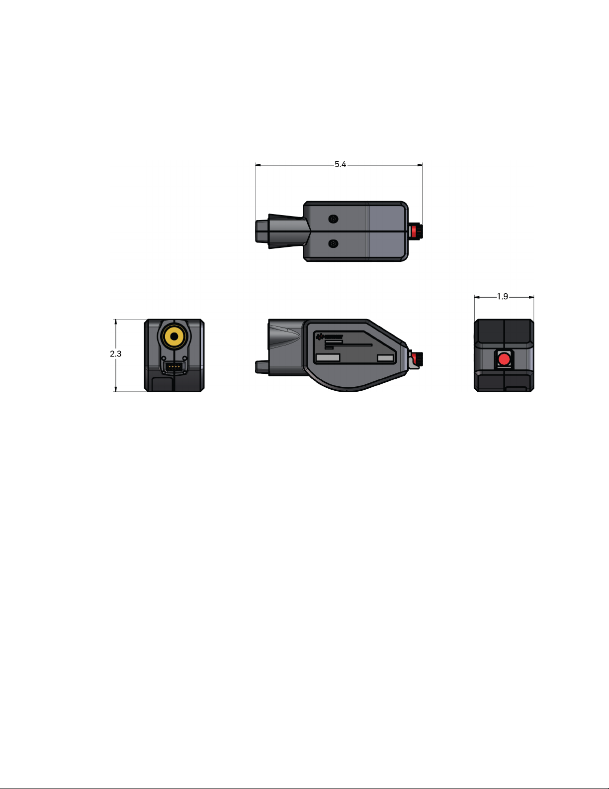
The N7004A dimensions shown below are in Inches.
10 N7004A 33GHz Optical-to-Electrical-Converter User Guide
Page 11

N7004A 33GHz Optical-to-Electrical-Converter
User Guide
2 Setting up the N7004A O/E
Converter
Prerequisites / 12
Step 1 - Clean the Fiber-Optic Connectors / 14
Step 2 - Connect the N7004A Output to a Compatible Keysight Oscilloscope / 18
Step 3 - Connect a Fiber-optic Cable to the N7004A Optical Input Connector / 19
Step 4- Configure the N7004A Setup on the Infiniium Software / 21
Step 5 - Perform Dark Calibration / 28
Page 12
2 Setting up the N7004A O/E Converter
NOTE
CAUTION
Prerequisites
Before you start using the N7004A O/E Converter, ensure that the following prerequisites are met.
Prerequisites
Compatible Oscilloscopes Adapter Required Oscilloscope Software
- V-Series
- Z-Series
- 90000 Q-Series
- 90000 X-Series
UXR-Series (13-33GHz) None Infiniium baseline software version 10.0 or
UXR-Series (40GHz or higher) N2852A AutoProbe II to AutoProbe
None Infiniium baseline software version 5.70 or
III Interface adapter)
higher
higher
Infiniium baseline software version 10.10 or
higher
The N2852A AutoProbe II to AutoProbe III Interface adapter allows you to
connect the N7004A (with the AutoProbe II interface) to a Keysight UXR-Series
40GHz or higher Infiniium oscilloscope (with the AutoProbe III interface).
To know more about the N2852A adapter, visit
http://www.keysight.com/find/N2852A and then download the adapter’s user
guide available in the Document Library tab.
Care should be taken while handling the N2852A adapter's RF cable. Avoid
bending this cable backwards or kinking the cable to ensure measurements
accuracy.
Is Your Oscilloscope Software Up-to-Date?
Keysight periodically releases software updates to support your probe, fix known defects, and
incorporate product enhancements. To download the latest firmware, go to www.keysight.com and
search for your oscilloscope’s series. Then click on the “Drivers, Firmware & Software” tab.
Oscilloscope Bandwidth Requirements
The real-time oscilloscope bandwidth that you need when using the N7004A is calculated as:
Oscilloscope bandwidth >= Optical data rate (Gbps) * 0.75 * 3/2
For example, if the optical data rate is 10 Gbps, then the oscilloscope bandwidth requirement is:
10 Gbps * 0.75 * 3/2 which is equal to 11.25 GHz.
Based on the above-mentioned calculations, the following table provides a list of the recommended
bandwidth of V-series Infiniium oscilloscopes needed for various optical data rates operations.
12 N7004A 33GHz Optical-to-Electrical-Converter User Guide
Page 13

Setting up the N7004A O/E Converter 2
Optical Data Rates Reference Receiver Bessel
Thomson Bandwidth
(0.75 * optical data rate)
4.25 Gbps 3.1875 GHz >4.78 GHz 8 GHz
10 Gbps 7.5 GHz >11.25 GHz 13 GHz
25 Gbps 18.75 GHz >28.125 GHz 33 GHz
28 Gbps 21 GHz >31.5 GHz 33 GHz
Oscilloscope Bandwidth
Requirement
(3/2 * Reference Receiver
Bandwidth)
Recommended Bandwidth
(Values are given for
V-series Oscilloscopes)
N7004A 33GHz Optical-to-Electrical-Converter User Guide 13
Page 14
2 Setting up the N7004A O/E Converter
CAUTION
NOTE
Step 1 - Clean the Fiber-Optic Connectors
Fiber-optic connectors are very sensitive, easy to damage, and expensive to replace. These
connectors can be easily damaged when connected to dirty or damaged cables and accessories.
Therefore, you must clean the fiber ends of the N7004A fiber-optic connector and the mating
fiber-optic cable or patch cable before each and every time a connection is made.
Damage to the fiber-optic connectors can:
• Degrade measurement accuracy and repeatability.
• Cause expensive damage to instruments.
Repair of the N7004A connector damaged due to lack of cleaning, improper
use, or improper cleaning procedures is NOT covered under warranty.
Keep fiber-optic connectors covered when not in use. The N7004A
shipment includes protective plastic caps for covering its fiber-optic
connector.
To visually inspect the fiber-ends
The visual inspection of the fiber-ends can help you identify any damage to the ferrule or end of the
fiber, any stray particles, or finger oil that can have a significant effect on connector performance.
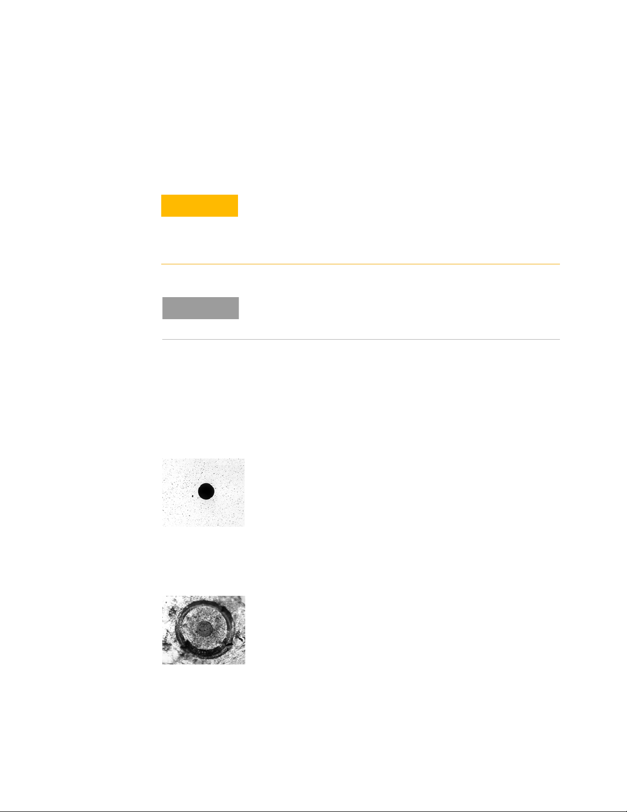
The following picture shows the end of a clean, problem-free fiber-optic connector. The dark center
circle is the fiber's 125 mm core and cladding which carries the light. The surrounding area is the
ferrule.
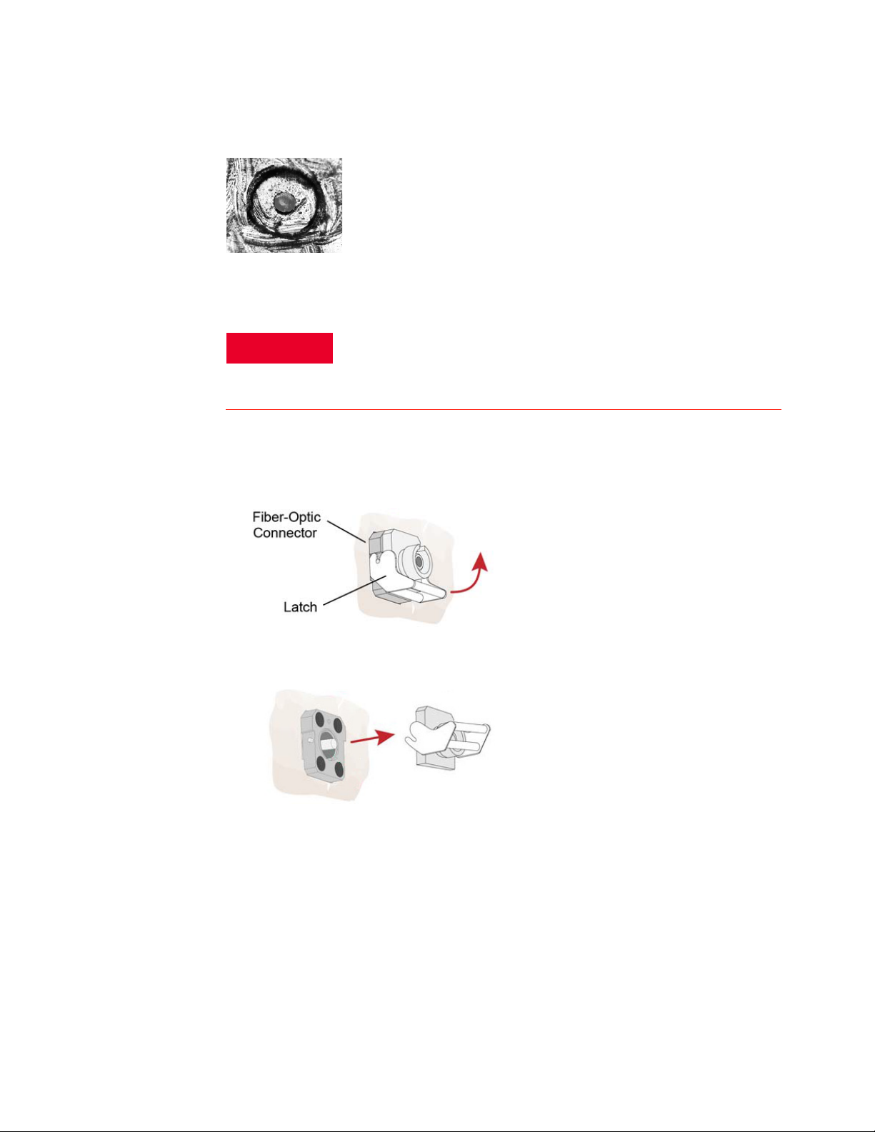
The following picture shows a fiber end that is dirty from neglect or improper cleaning. Loose
particles or oils are smeared and ground into the end of the fiber causing light scattering and poor
reflection. Not only is the precision polish lost, but this action can also grind off the glass face and
destroy the connector.
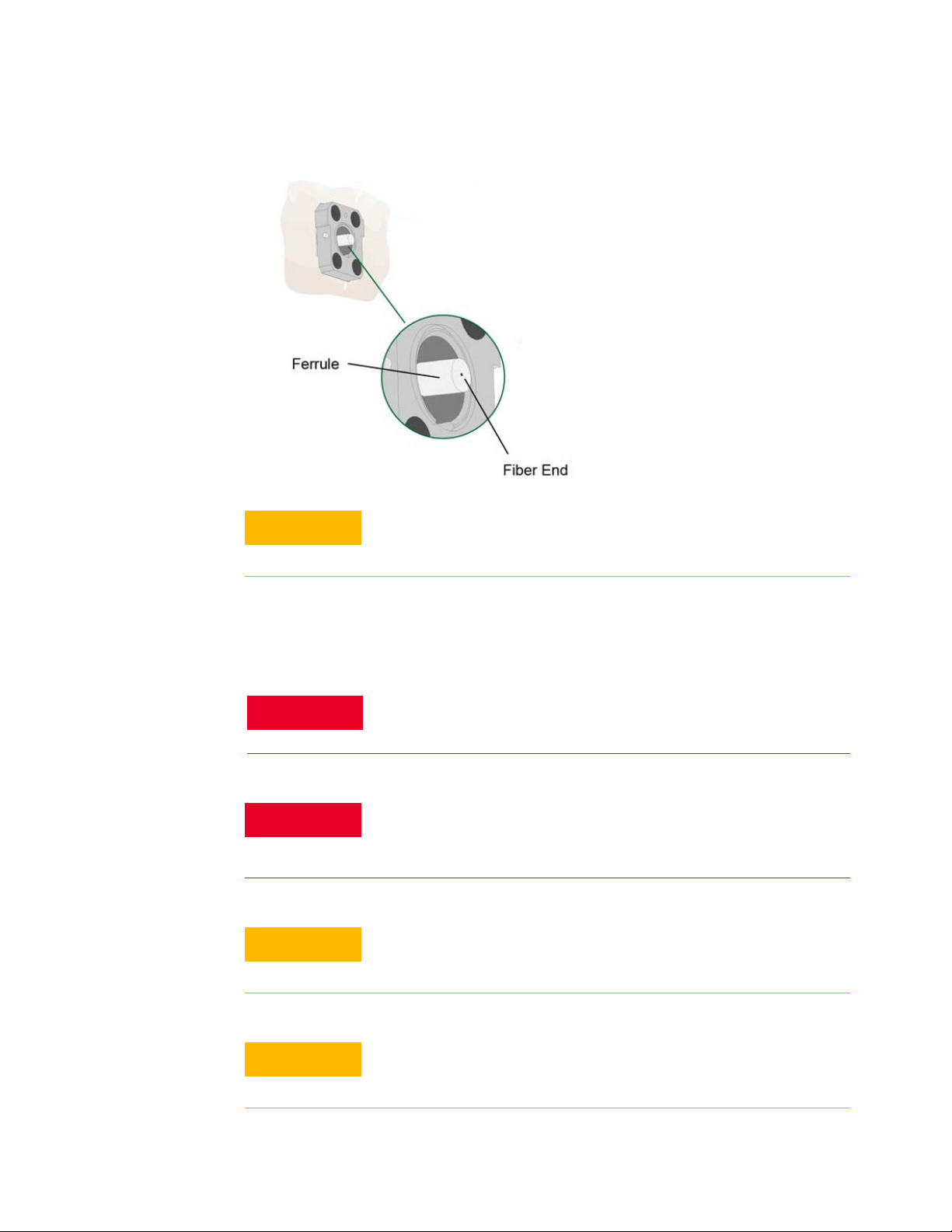
The following picture shows physical damage to the glass fiber end caused by either repeated
connections made without removing loose particles from the fiber end or by using improper cleaning
tools. This damage can be severe enough to transfer the damage from the connector end to a good
connector that comes in contact with it.
14 N7004A 33GHz Optical-to-Electrical-Converter User Guide
Page 15
Use a microscope (100X to 200X magnification) to inspect the entire end face for contamination,
WARNING
raised metal, dents in the metal, and any other imperfections. Visible imperfections not touching the
fiber core may not affect performance, unless the imperfections keep the fibers from contacting.
Always remove both ends of fiber-optic cables from any instrument, system,
or device before visually inspecting the fiber-ends. Disable all optical
sources before disconnecting fiber-optic cables. Failure to do so may result
in permanent injury to your eyes.
To clean the fiber-end of the N7004A fiber-optic connector
1 Lift the latch of the fiber-optic connector.
Setting up the N7004A O/E Converter 2
2 Carefully pull off the receptacle without touching the ferrule or fiber end. This will expose the
fiber-end for cleaning.
3 Clean the fiber-optic end using a professional fiber-optic cleaning product. A variety of products
are available and are easily located via an Internet search on "fiber optic cleaning products". You
can purchase tools designed specifically for the type of fiber-optic cable that you are using. You
can also use a cloth or a swab with alcohol to clean.
N7004A 33GHz Optical-to-Electrical-Converter User Guide 15
Page 16
2 Setting up the N7004A O/E Converter
CAUTION
WARNING
WARNING
CAUTION
CAUTION
Never use metal or sharp objects to clean a connector and never scrape the
connector.
To clean the fiber-end of the mating fiber-optic cable or patch cable
a Use a clean wipe each time you need to clean the mating cable. Wipes that are available in a
dispenser are recommended for cleaning.
If flammable cleaning materials are used, the material shall not be stored, or
left open in the area of the equipment. Adequate ventilation shall be assured
to prevent the combustion of fumes, or vapors.
Cleaning connectors with alcohol shall only be done with the instruments
power cord removed, and in a well-ventilated area. Allow all residual alcohol
moisture to evaporate and the fumes to dissipate prior to energizing the
instrument.
Do not use any type of foam swab to clean optical fiber ends. Foam swabs
can leave filmy deposits on fiber ends that can degrade performance.
Do not scrub during this initial cleaning because grit can be caught in the
swab and become a gouging element.
16 N7004A 33GHz Optical-to-Electrical-Converter User Guide
Page 17

Setting up the N7004A O/E Converter 2
CAUTION
CAUTION
Do not shake, tip, or invert compressed air canisters, because this releases
particles in the can into the air. Refer to instructions provided on the
compressed air canister.
Keysight Technologies strongly recommends that index matching
compounds not be applied to their instruments and accessories. Some
compounds, such as gels, may be difficult to remove and can contain
damaging particulates. If you think the use of such compounds is necessary,
refer to the compound manufacturer for information on application and
cleaning procedures.
N7004A 33GHz Optical-to-Electrical-Converter User Guide 17
Page 18
2 Setting up the N7004A O/E Converter
Step 2 - Connect the N7004A Output to a Compatible Keysight Oscilloscope
On connecting,
• the oscilloscope automatically recognizes the N7004A.
• The S-parameters are automatically read to adjust the system response and the N7004A is
displayed in the Infiniium software GUI for setup and configuration.
• The vertical unit is changed to Watts in the Infiniium software GUI.
18 N7004A 33GHz Optical-to-Electrical-Converter User Guide
Page 19

Setting up the N7004A O/E Converter 2
CAUTION
Step 3 - Connect a Fiber-optic Cable to the N7004A Optical Input Connector
Selection of the Fiber-optic Cable
• You can use a 9/125 µm single mode or a 50/125 µm multimode fiber-optic cable that has an
FC/PC connector.
• If your fiber has a connector other than FC/PC, then you can use a LC-to-FC or SC-to-FC
patch cord to establish connectivity with the N7004A.
• Ensure that you use a fiber patch cord with ceramic fiber-optic ferrule.
Guidelines for Making the Connection
When inserting a fiber-optic cable into a connector:
• Gently insert it in as straight a line as possible. Tipping and inserting at an angle can scrape
material off the inside of the connector or even break the inside sleeve of connectors made with
ceramic material.
• Ensure that the fiber end does not touch the outside of the mating connector or adapter.
• Avoid over tightening connections. Unlike common electrical connections, tighter is not better.
The purpose of the connector is to bring two fiber ends together. Once they touch, tightening only
causes a greater force to be applied to the delicate fibers.
With connectors that have a convex fiber end, the end can be pushed off-axis resulting in
misalignment and excessive return loss. Many measurements are actually improved by backing
off the connector pressure. Also, if a piece of grit does happen to get by the cleaning procedure,
the tighter connection is more likely to damage the glass. Tighten the connectors just until the
two fibers touch.
• Use fusion splices on the more permanent critical nodes. Choose the best connector possible.
Replace connecting cables regularly. Frequently measure the return loss of the connector to
check for degradation, and clean every connector, every time.
To avoid damage to the N7004A’s fiber-optic connector, use proper cleaning techniques.
Refer to “Step 1 - Clean the Fiber-Optic Connectors" on page 14.
Aligning the Keying Features while Making the Connection
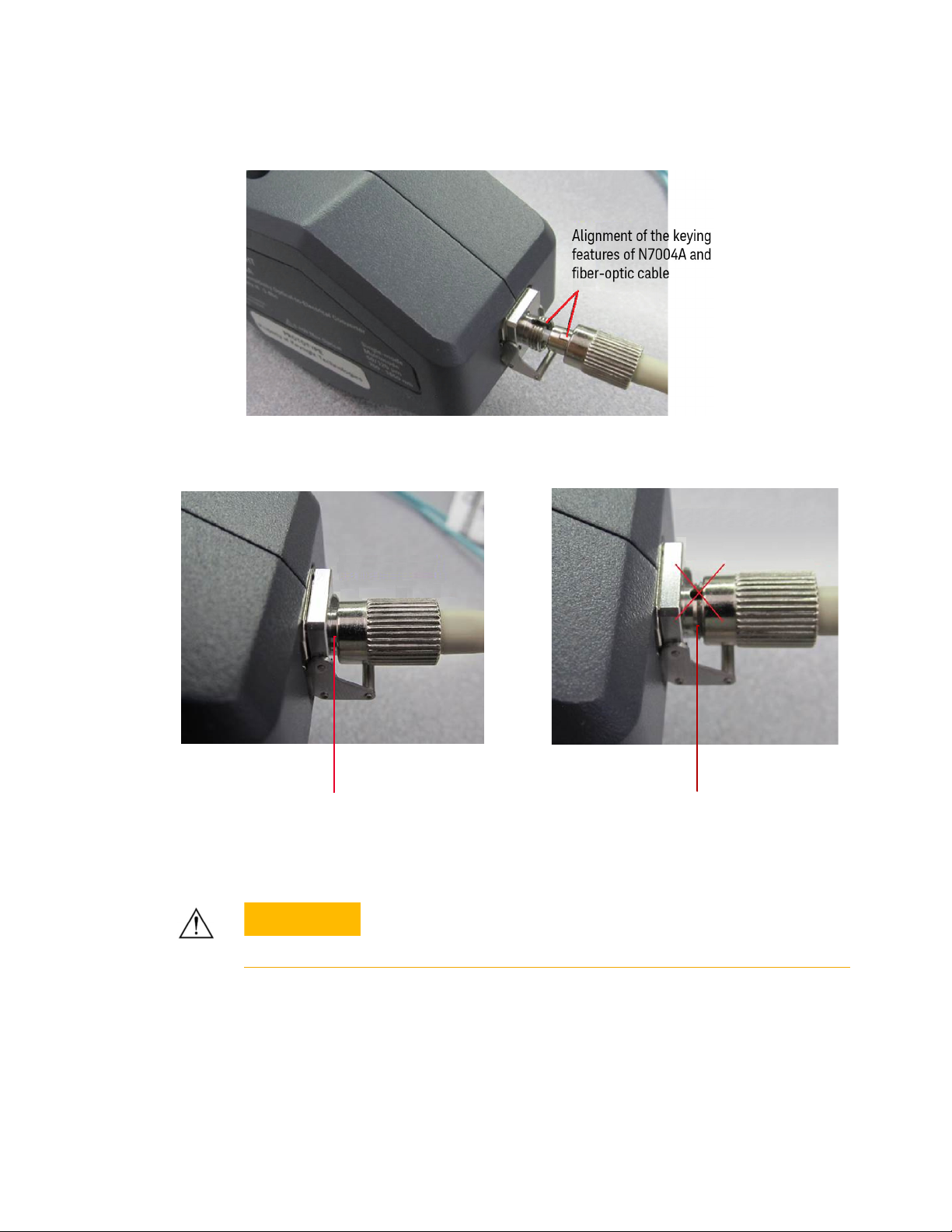
While securing the connection between the N7004A and fiber-optic cable, ensure that the keying
features of both the N7004A FC/PC Input connector and fiber-optic cable’s connector are aligned
properly before you start finger-tightening the connection. Misaligned keys can adversely affect the
optical signal transmission.
N7004A 33GHz Optical-to-Electrical-Converter User Guide 19
Page 20
2 Setting up the N7004A O/E Converter
Keying features are
aligned and connection is
finger-tight
Keying features are
misaligned but
connection is finger-tight
CAUTION
The following are the examples of finger-tightened connections, one with the keying features
properly aligned and the other with the keying features misaligned.
The input circuitry of the N7004A can be damaged when total input power
levels exceed 8mW. To prevent damage, this specified level must not be
exceeded.
20 N7004A 33GHz Optical-to-Electrical-Converter User Guide
Page 21
Step 4- Configure the N7004A Setup on the Infiniium Software
Selecting the Wavelength
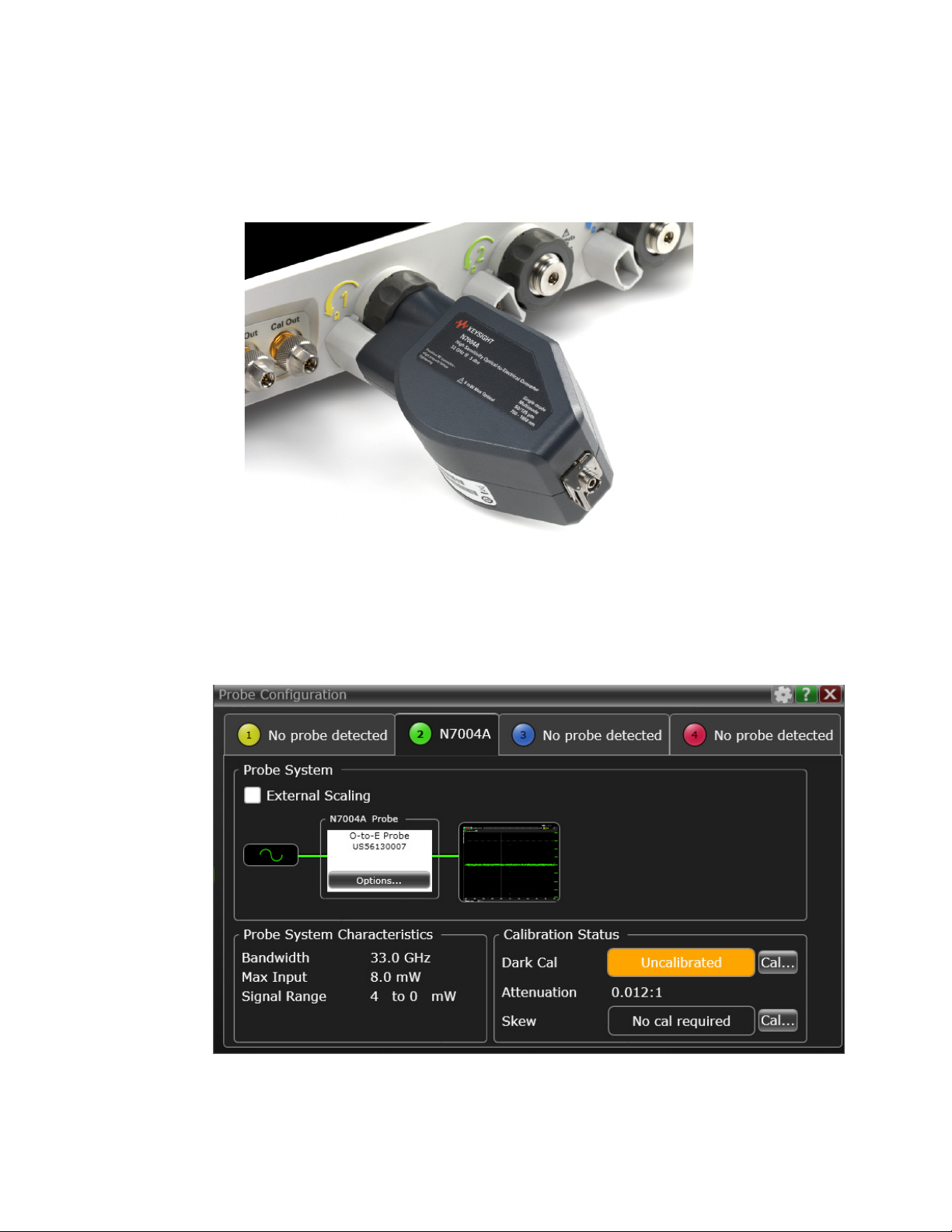
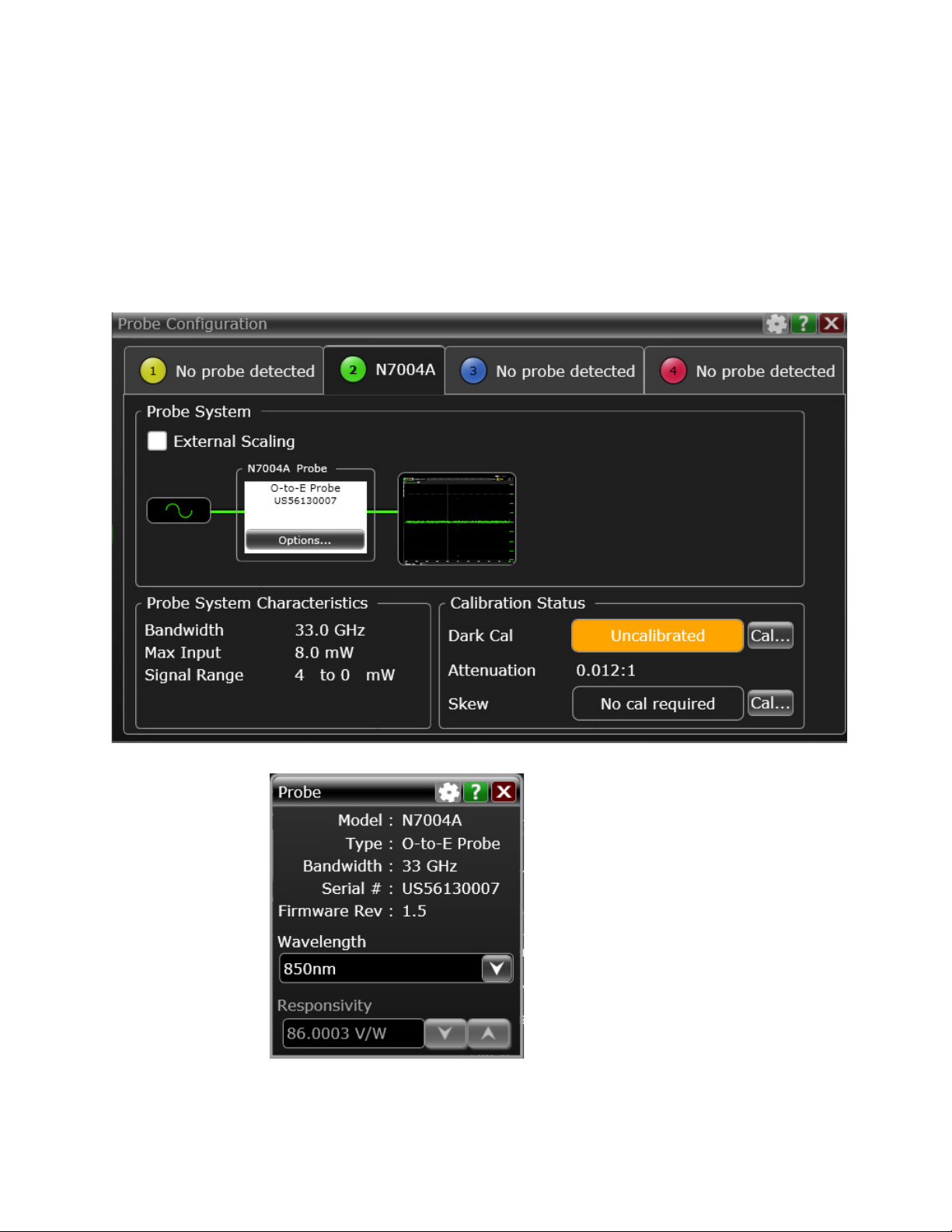
1 In the Infiniium software GUI, choose Setup > Probe Configuration... to open the Probe Configuration
dialog box. Notice that the N7004A is recognized and displayed as connected to the scope’s
channel.
Setting up the N7004A O/E Converter 2
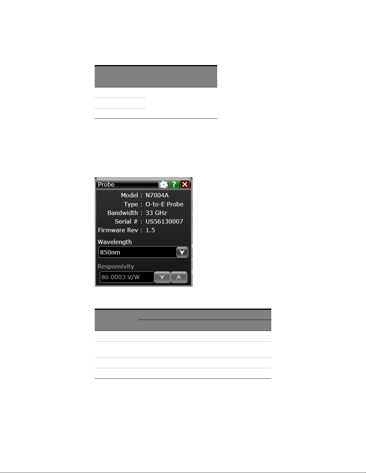
2Click Options... displayed under N7004A to set the wavelength for N7004A.
3 Select the required wavelength. N7004A supports the following wavelengths:
N7004A 33GHz Optical-to-Electrical-Converter User Guide 21
Page 22
2 Setting up the N7004A O/E Converter
Predefined
(Factory-calibrated)
Wavelengths
850 nm Wavelength should be in the range of
1310 nm
1550 nm
User-defined Wavelengths
750 to 1650 nm.
Adjusting Conversion Gain for a User-defined Wavelength
If you select a predefined wavelength, the N7004A’s predefined responsivity value for this
wavelength is displayed in the Responsivity field. Based on the selected predefined wavelength, the
N7004A’s conversion gain is therefore automatically adjusted to provide an accurate measurement
of the signal’s average optical power.
Responsivity Vs. Wavelength
Wavelength
850nm Multimode: –68 V/W Multimode: –75 V/W
1310 nm Multimode/Single Mode: –105
V/W
1550nm Single Mode: –105 V/W Single Mode: –110 V/W
User-defined To be manually adjusted
Responsivity (Conversion Gain)
Minimum Typ ic al
Multimode/Single Mode: –110
V/W
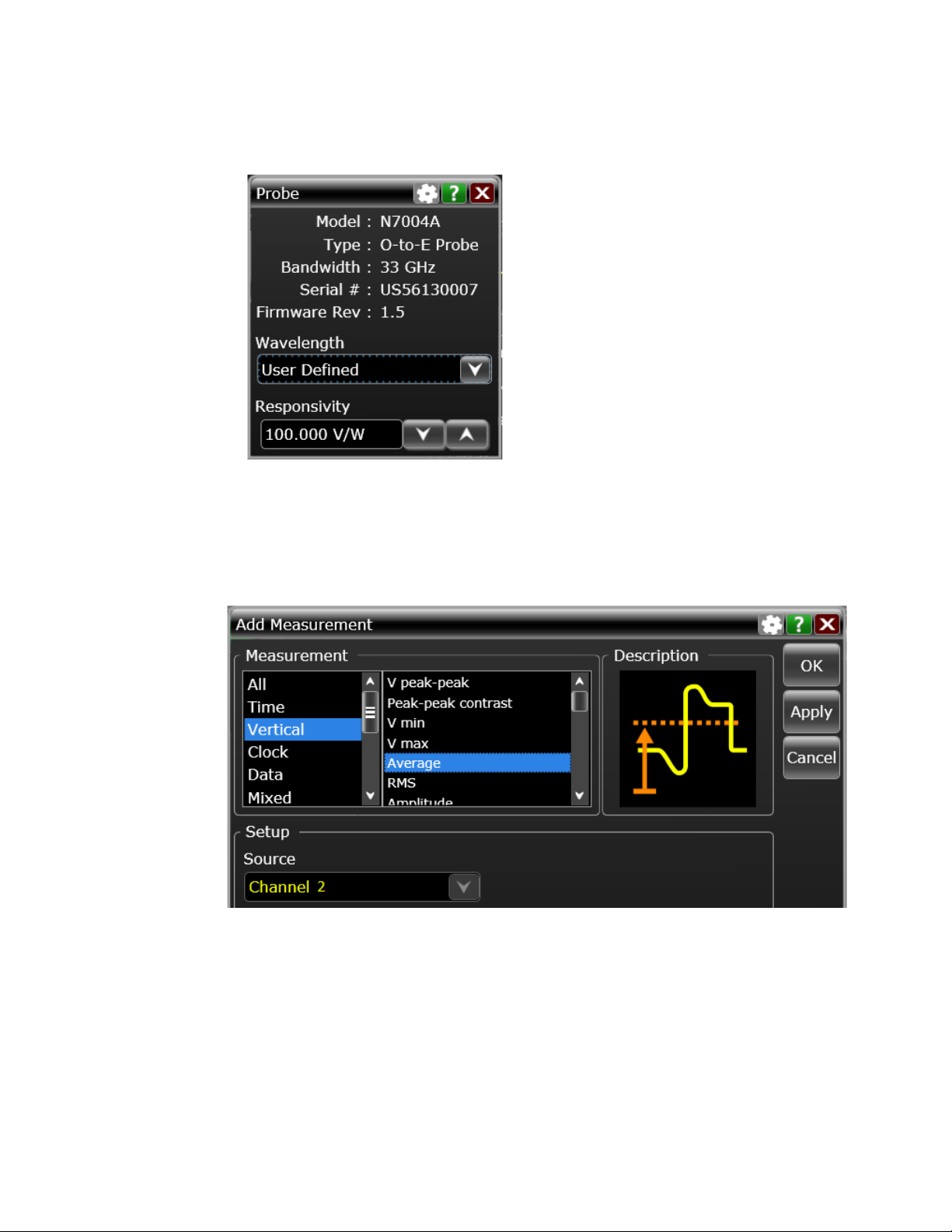
If you select the User Defined wavelength option, then you need to manually specify and adjust the
Responsivity value in the Responsivity field to adjust the N7004A’s conversion gain for this
user-defined wavelength.
22 N7004A 33GHz Optical-to-Electrical-Converter User Guide
Page 23
Setting up the N7004A O/E Converter 2
To determine the responsivity value for a user-defined wavelength
1 Measure the optical signal using an optical power meter.
2 Transmit this signal to the N7004A. This may be an active signal or just a DC optical level.
3Set up the Vaverage measurement for the waveform on the Infiniium software GUI. This
measurement is available under the Vertical Measurements group.
4 For the user-defined wavelength, the Responsivity field is enabled to allow you to adjust the
responsivity value. Adjust the Responsivity value in this field until the Vaverage measurement
agrees with the power level determined by the optical power meter in step1.
N7004A 33GHz Optical-to-Electrical-Converter User Guide 23
Page 24
2 Setting up the N7004A O/E Converter
NOTE
On selecting the User-defined wavelength option, the Optical Average Power measurement
displays the value “Responsivity?” instead of the average optical power value. This is because
this measurement is calibrated based on the selected wavelength and in case of a
user-defined wavelength, there is no calibration factor available for this measurement.
Configuring the Bandwidth Limits for the Oscilloscope and its Channel
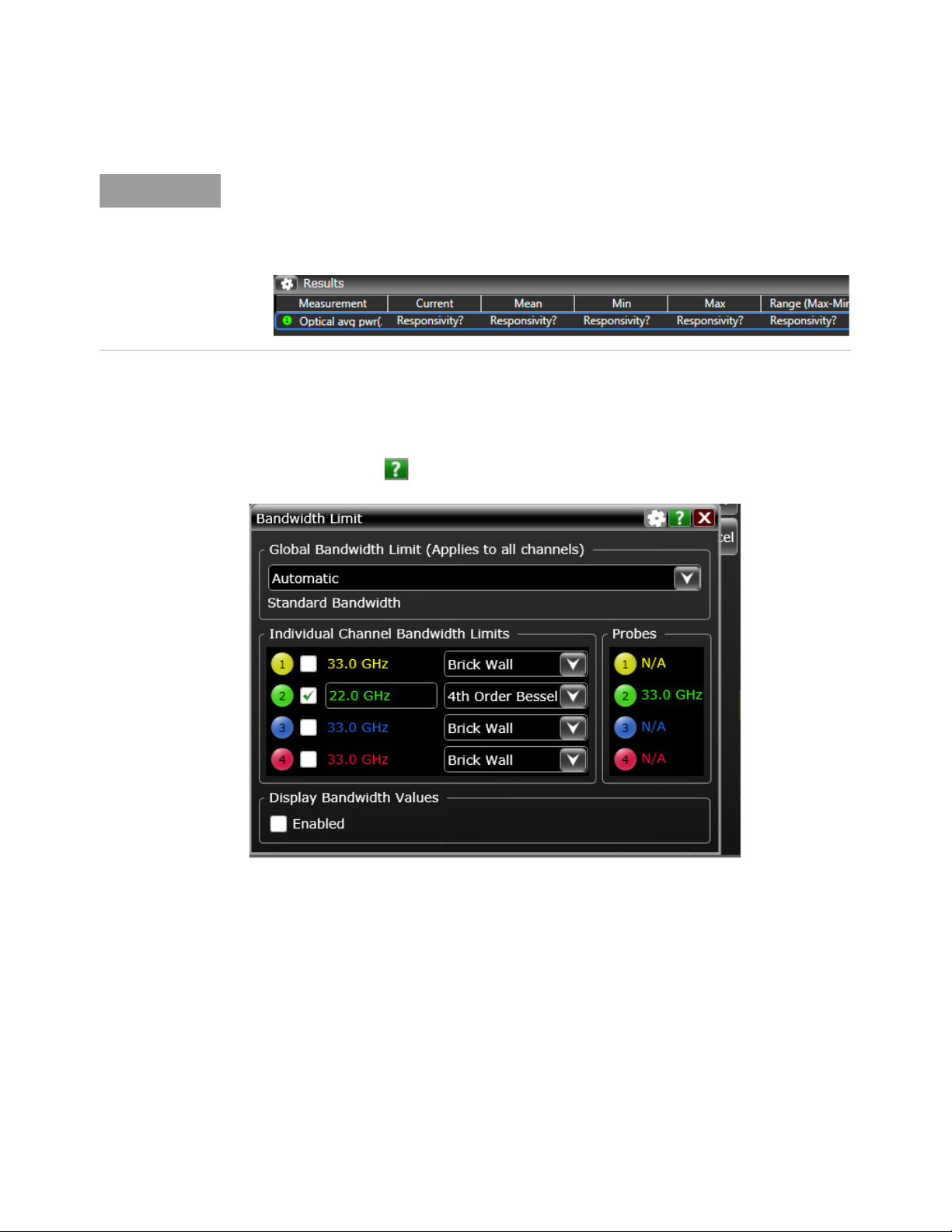
You use the Bandwidth Limit dialog box to set the bandwidth limit for the oscilloscope and the
individual channel to which you have connected the N7004A. You may want to reduce bandwidth
settings for improved noise performance. For details on how to set bandwidth limits on the
oscilloscope, click the icon in the Bandwidth Limit dialog box.
Individual Channel Bandwidth Limit Filters
When setting the bandwidth limits, you can select one of the following two bandwidth limit filters for
the channel to which the N7004A is connected.
24 N7004A 33GHz Optical-to-Electrical-Converter User Guide
Page 25
Setting up the N7004A O/E Converter 2
NOTE
Brick Wall 4th Order Bessel Thomson
Suitable when you want to characterize the raw response of the optical
transmitter under test.
The maximum bandwidth limit that you can specify can be the same as
the N7004A’s bandwidth limit, that is, 33 GHz.
Suitable when you want to do reference receiver testing of industry-standard
optical measurements on the optical transmitter under test.
This filter limits the bandwidth to optimize the signal-to-noise ratio but does
not lower it down to the extent of causing inter-symbol interference. This
allows the waveform to be displayed similar to what a receiver would see.
The maximum bandwidth limit that you can specify is about 2/3 of the
maximum bandwidth you could specify with the Brick-Wall filter.
For a 33 GHz oscilloscope with the Bessel Thomson filter on, this yields a 22
GHz Bessel Thomson filter, which covers 28 Gbps x 0.75 = 21 GHz.
While setting up the bandwidth limits, refer to the topic “Oscilloscope Bandwidth Requirements" on
page 12 to know how much oscilloscope bandwidth is needed based on your optical data rates
requirements.
Adjusting the Vertical Settings for the Oscilloscope Channel
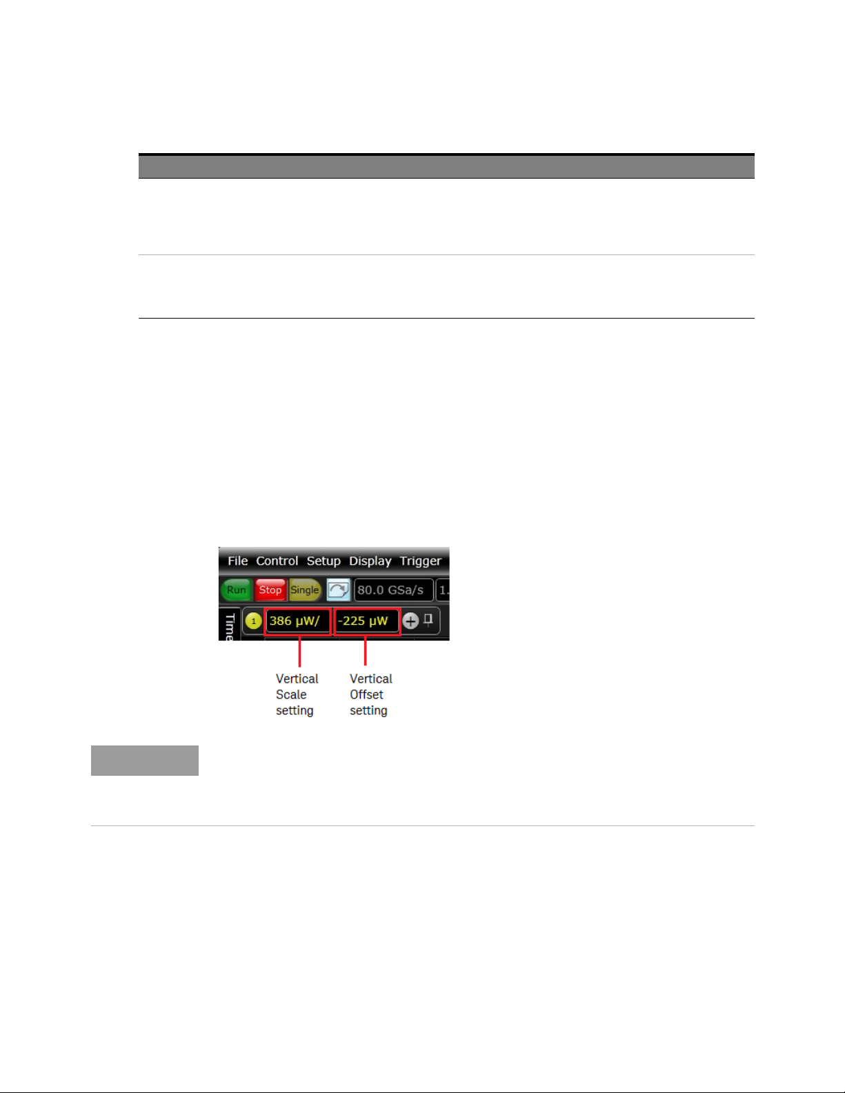
Adjust the vertical scale (Watts per division) and offset settings for the oscilloscope channel to which
you connected the N7004A O/E Converter. For the extinction ratio measurement, this step is critical
as the vertical settings affect the magnitude of the dark level offset which can affect the accuracy of
this measurement.
You can adjust the vertical settings using the options displayed in the Infiniium software GUI or using
the vertical scale and offset knobs of the oscilloscope.
The Vertical scale of an oscilloscope channel is displayed in Watts when you connect the
N7004A O/E Converter to the channel.
Adjust the vertical scale and offset levels in such a way that the output levels are completely
on the screen and the eye diagram uses the full display.
Adding and Configuring Optical Measurements
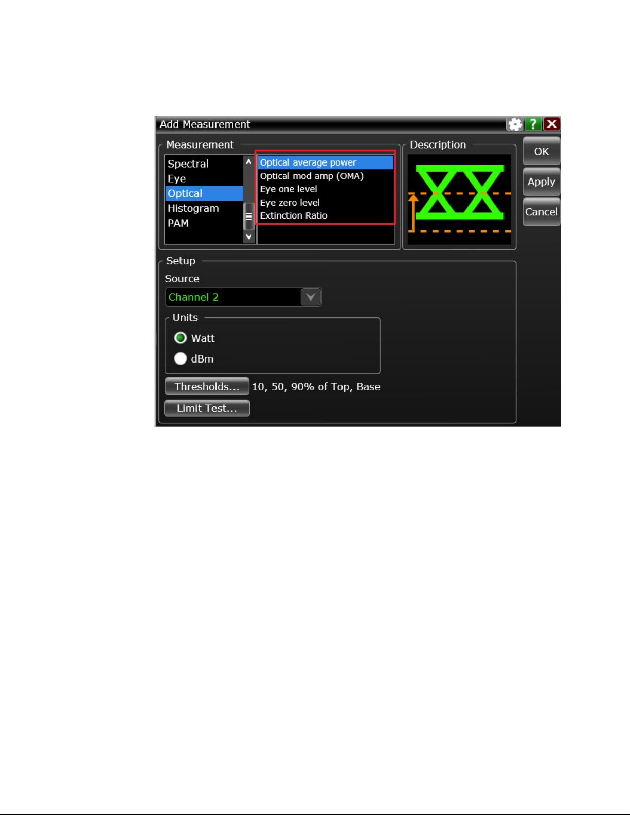
1Click Measure > Add Measurement to access the Add Measurement dialog box.
2 Select and add the required optical measurements from the set of measurements displayed
under the Optical group in the Add Measurement dialog box.
N7004A 33GHz Optical-to-Electrical-Converter User Guide 25
Page 26
2 Setting up the N7004A O/E Converter
26 N7004A 33GHz Optical-to-Electrical-Converter User Guide
Page 27
Setting up the N7004A O/E Converter 2
NOTE
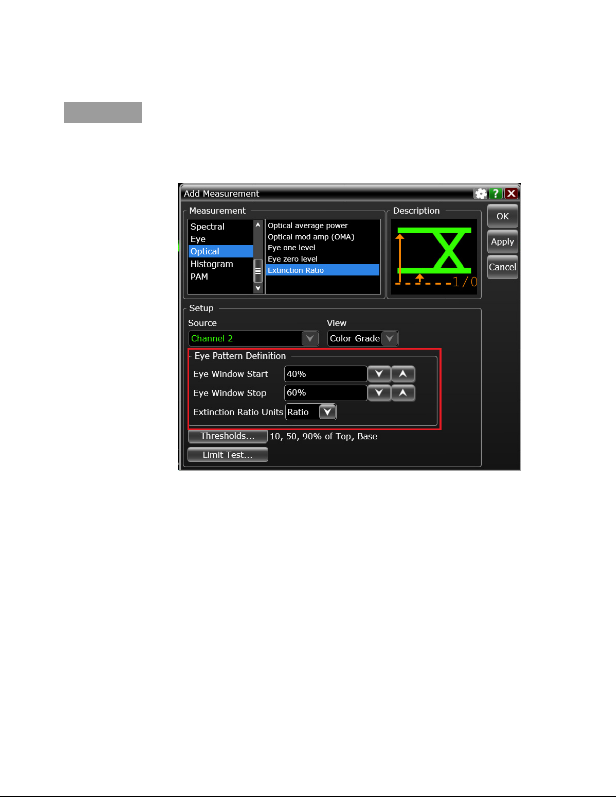
For measurements such as the Extinction ratio measurement, you may want to define settings
such as eye pattern settings used to make eye waveform measurements. You can do this while
adding the measurement using the Add Measurement dialog box.
Refer to the Optical Measurements help topics in the online help of your Infiniium oscilloscope
to get a detailed description of each of the optical measurements.
N7004A 33GHz Optical-to-Electrical-Converter User Guide 27
Page 28
2 Setting up the N7004A O/E Converter
NOTE
NOTE
Step 5 - Perform Dark Calibration
After you have configured the N7004A settings and the optical measurement setup on the Infiniium
software, you can perform dark calibration for N7004A.
What is Dark Calibration
Dark calibration is the process of factoring out the power transmitted by the N7004A when there is
no light being transmitted. For this calibration, the optical input of the N7004A is covered to block
light completely.
In this calibration, the oscilloscope identifies the offset (dark level) signals internally generated by
N7004A when no light is present at the input channel. These internal offset signals are then removed
by the oscilloscope from the extinction ratio calculations to ensure accurate measurement results.
When the Extinction Ratio measurement is performed, the oscilloscope mathematically
removes the offset error measured by dark calibration from the extinction ratio calculation.
Therefore, if you plan to make the Extinction Ratio measurement, it is highly recommended
that you perform dark calibration to maximize the accuracy in this measurement’s results.
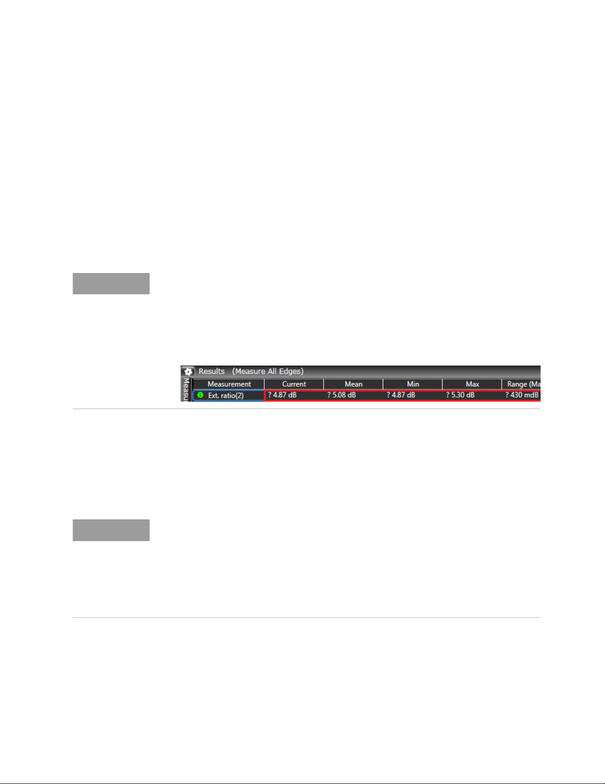
A “?” is displayed with the Extinction Ratio measurement results if dark calibration is not
valid.
When to perform Dark Calibration
Dark calibration is only valid for a given vertical scale, offset, and sample rate of the oscilloscope. A
change in any of these invalidates the calibration and you have to perform dark calibration again.
Therefore, you must perform dark calibration as the last step just before making optical
measurements when you have set the vertical scale and offset at which you want to make your
measurements.
You need to perform dark calibration again when:
- vertical scale or offset is changed.
- sample rate is changed.
- ±2°C temperature change from the calibration temperature.
- wavelength or responsivity is changed.
- power is recycled.
To perform dark calibration
1 Allow the N7004A to warm up for15 minutes before starting the calibration.
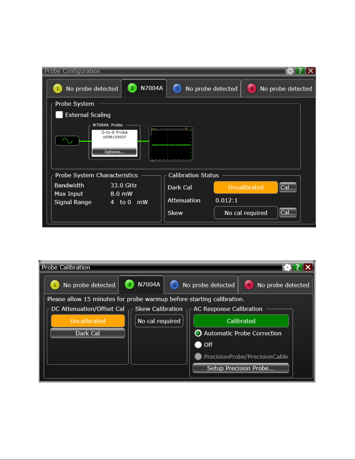
2Choose Setup > Probe Configuration...
The Probe Configuration... dialog box is displayed.
28 N7004A 33GHz Optical-to-Electrical-Converter User Guide
Page 29
Setting up the N7004A O/E Converter 2
3In the Calibration Status section, the Dark Cal status is currently displayed as Uncalibrated. Click the
Cal... button.
The Probe Calibration dialog box is displayed.
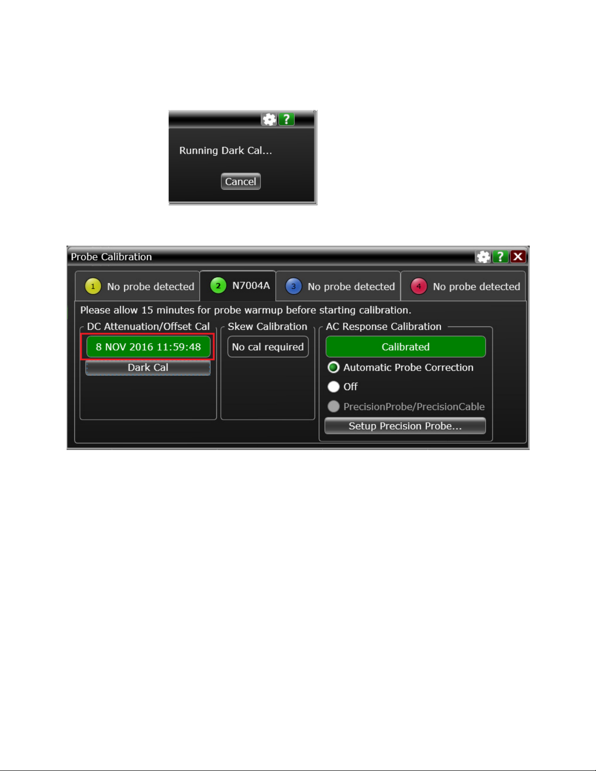
4 Cover the N7004A’s FC/PC input connector with the cap that accompanies the N7004A.
5Click the Dark Cal button to begin dark calibration.
N7004A 33GHz Optical-to-Electrical-Converter User Guide 29
Page 30
2 Setting up the N7004A O/E Converter
If the dark calibration competes successfully, the date and time of its completion is shown on
screen. If it fails, the status is displayed as Uncalibrated.
6 After the dark calibration is successfully complete, remove the cap from the N7004A and
reconnect the fiber-optic cable to the N7004A.
The setup is now complete to start making the measurements.
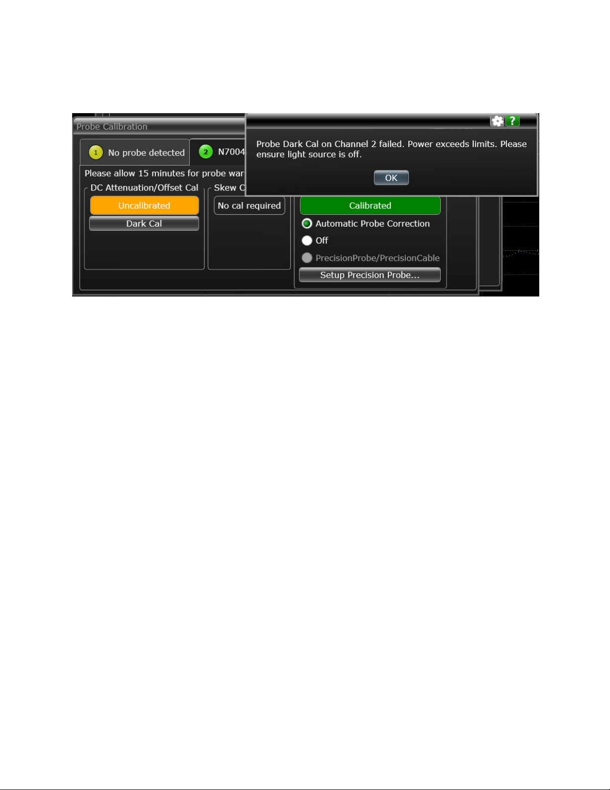
Reasons for the Failure of the Dark Calibration
• The N7004A optical input is not covered properly or the optical source is not turned off.
• The dark level (signal with the light source off) is not on the Infiniium screen. This signal must be
completely on the screen to be correctly measured during dark calibration.
• The dark level (signal with the light source off) is less than 20mV converted to Watts by the
responsivity. The dark calibration should be performed after the signal has been scaled correctly.
It is recommended to set the vertical sensitivity of the oscilloscope so that the signal you try to
capture takes about 5-6 divisions high.
• The dark calibration is canceled by the user.
30 N7004A 33GHz Optical-to-Electrical-Converter User Guide
Page 31
Setting up the N7004A O/E Converter 2
N7004A 33GHz Optical-to-Electrical-Converter User Guide 31
Page 32

2 Setting up the N7004A O/E Converter
32 N7004A 33GHz Optical-to-Electrical-Converter User Guide
Page 33

N7004A 33GHz Optical-to-Electrical-Converter
User Guide
3 Making Optical Measure-
ments and Analyzing Results
N7004A Optical Measurements / 34
Performing Eye Mask Testing / 37
This chapter provides information on the optical measurements that you can make using the N7004A
on an Infiniium real-time oscilloscope. It also provides an overview of how you can use the N7004A to
perform eye mask testing.
Page 34
3 Making Optical Measurements and Analyzing Results
N7004A Optical Measurements
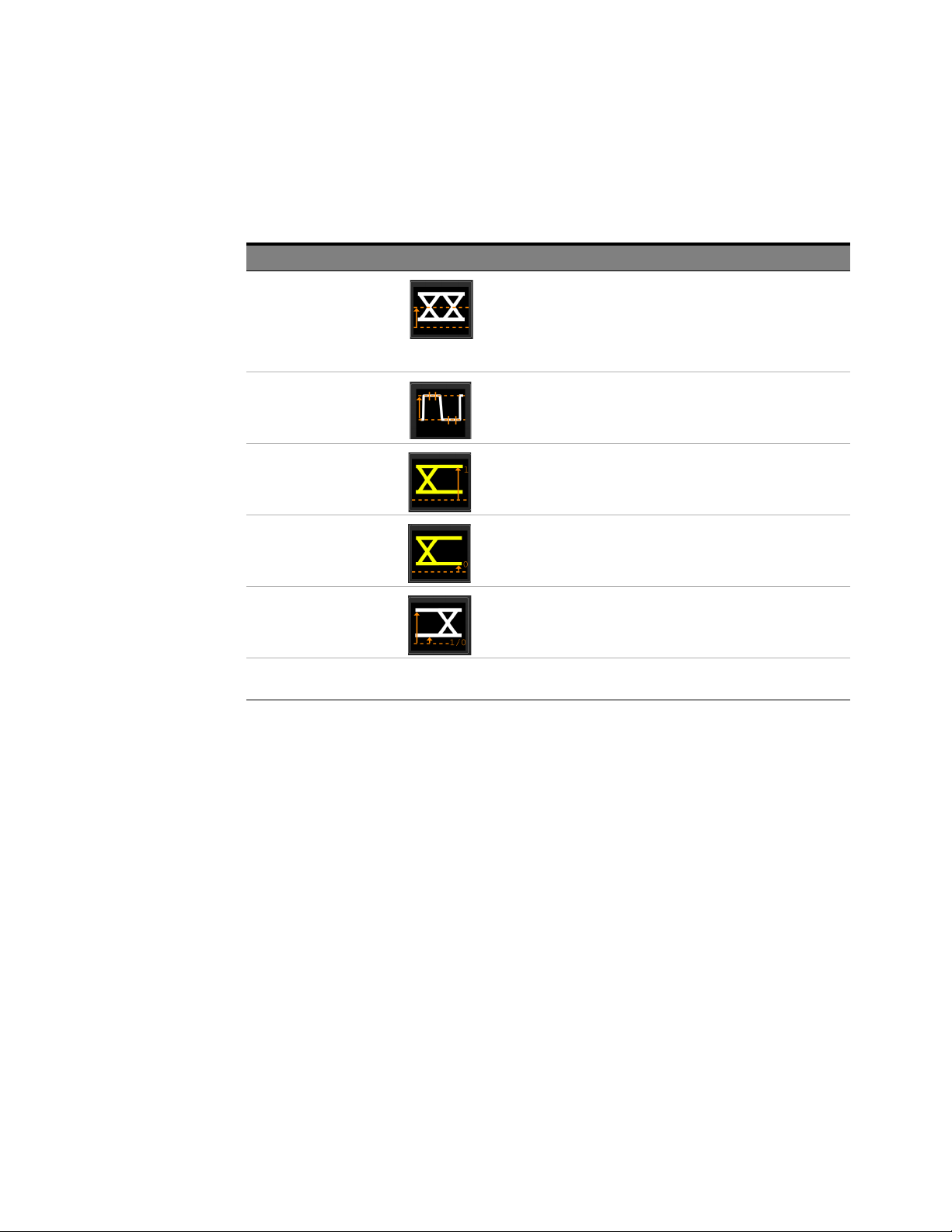
You can make the following optical measurements using the N7004A:
Optical Measurement Description
Optical Average Power Optical power is a measure of the true average component of an optical
Optical Modulation Amplitude
(OMA)
Eye One Level Eye one level is a measure of the mean value of the logical 1 of an eye
Eye Zero Level Eye zero level is a measure of the mean value of the logical 0 of an eye
Extinction Ratio Extinction Ratio is the ratio of the one level and the zero level of an eye
Refer to the Optical Measurements help topics in the online help of your Infiniium real-time oscilloscope to get a detailed description
of each of these measurements.
Optical Measurement Results
signal.
it differs from other measurements because it does not rely on the waveform
display to determine the measurement result. The analog-to-digital
converter in the N7004A allows the generation of this result independent of
the waveform displayed on the screen.
Optical Modulation Amplitude (OMA) is the measure of the difference
between the optical power of an NRZ (non-return-to-zero) one pulse and the
optical power of an NRZ zero pulse.
diagram.
diagram.
diagram of an optical signal.
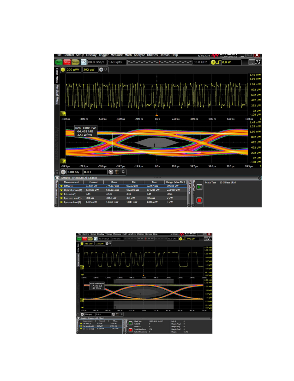
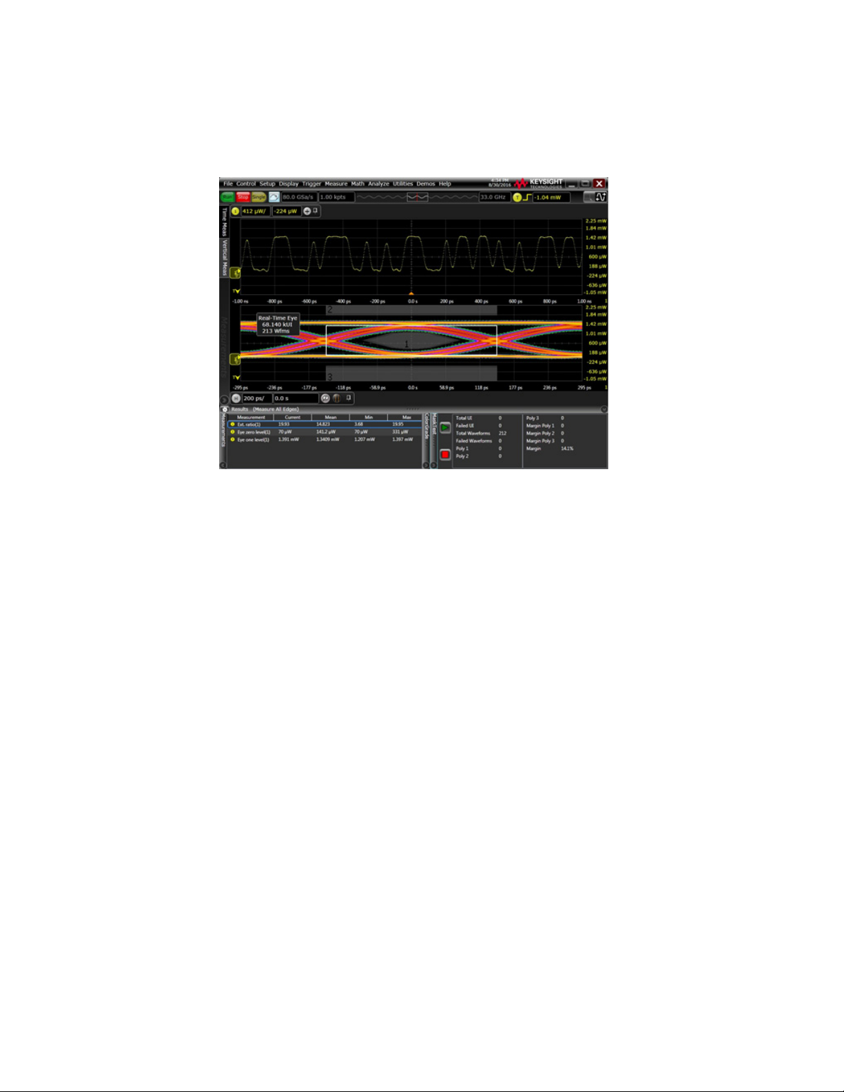
The following screens display sample optical data and optical measurements results as displayed on
an Infiniium oscilloscope connected to N7004A.
34 N7004A 33GHz Optical-to-Electrical-Converter User Guide
Page 35
Making Optical Measurements and Analyzing Results 3
Examples of Optical Data Acquired with N7004A for Different Optical Data Rates
For 10 Gbps data rate
N7004A 33GHz Optical-to-Electrical-Converter User Guide 35
Page 36
3 Making Optical Measurements and Analyzing Results
For 25 Gbps data rate
36 N7004A 33GHz Optical-to-Electrical-Converter User Guide
Page 37
Performing Eye Mask Testing
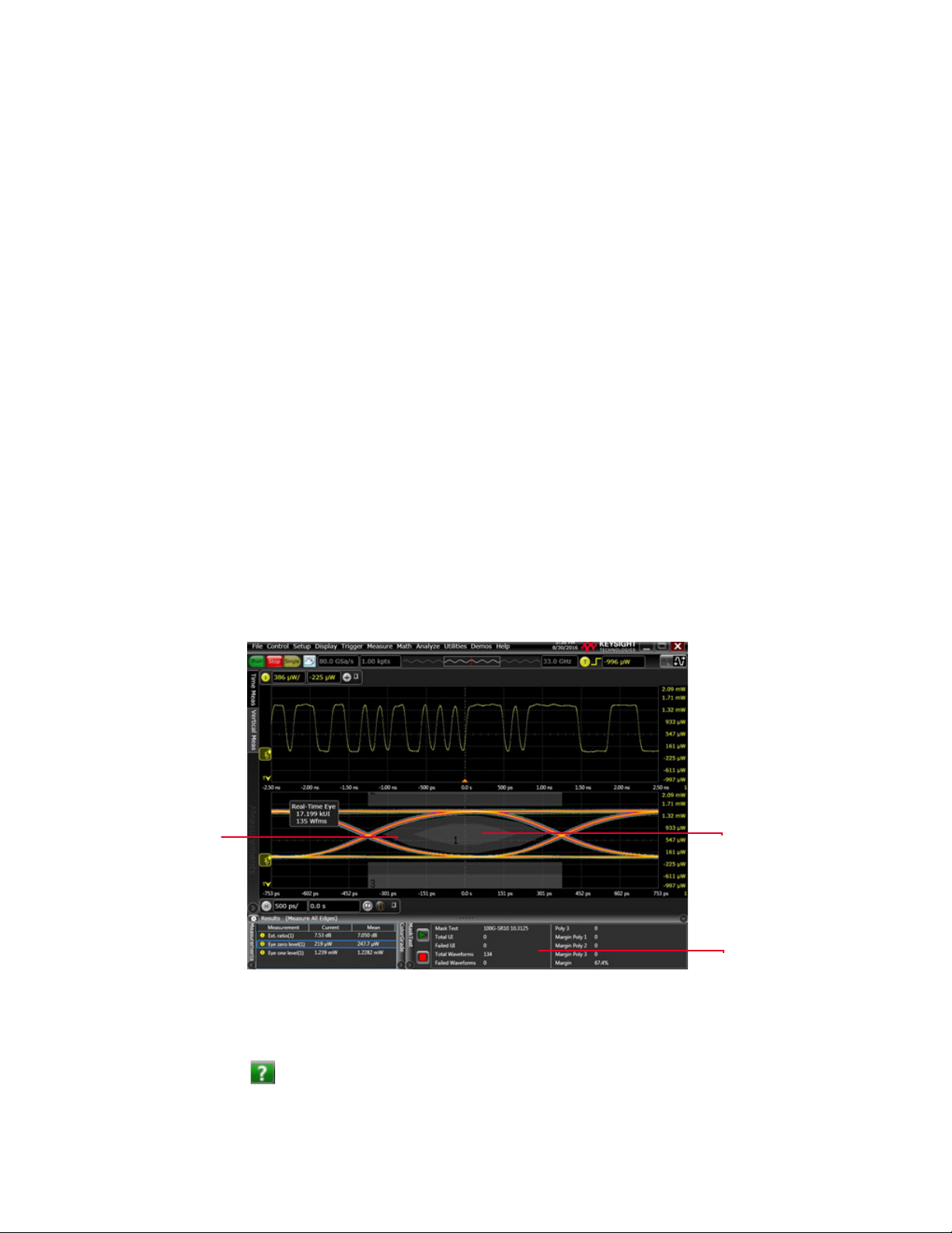
Mask Region
Mask Margin
Region
Mask Test panel
with results
When using the N7004A with an Infiniium oscilloscope, you can use the mask testing feature of the
oscilloscope to verify whether or not a displayed eye diagram complies with industry-standard
definitions for optical waveforms. A mask (template) defines the shaded mask regions in the display.
A waveform must remain outside these mask regions to meet the requirements of a standard. A data
point from a waveform that illuminates a pixel in the mask region causes a mask test failure.
Types of Masks Supported with N7004A
You can:
• either load standard masks (for Keysight DCA oscilloscopes). These are provided with the Infiniium
software for optical waveforms. These masks have the .mskx extension and are available at the
following location:
C:\Users\Public\Documents\Infiniium\Masks
• or create your own masks and load these in the Infiniium software.
• or use the Automask or the Draw Mask feature of the oscilloscope.
Mask Margins
Making Optical Measurements and Analyzing Results 3
You can also enable mask test margins to ensure that mask testing is performed using the defined
margins.
The following screen displays optical data with a standard mask applied. Mask regions are shown in
lighter shade of gray and mask margins are shown in darker shade of gray.
You use the Mask Test dialog box to enable and load a mask and the Mask Test Margins dialog box to
enable and specify margins for the mask.
To know in detail how you can implement mask testing and mask margins on your Infiniium
oscilloscope, refer to the Mask Testing help topics in the Infiniium online help. You can also click the
icon displayed in these dialog boxes.
N7004A 33GHz Optical-to-Electrical-Converter User Guide 37
Page 38

3 Making Optical Measurements and Analyzing Results
38 N7004A 33GHz Optical-to-Electrical-Converter User Guide
Page 39

N7004A 33GHz Optical-to-Electrical-Converter
User Guide
4 Remotely Controlling the
N7004A Measurement Setup
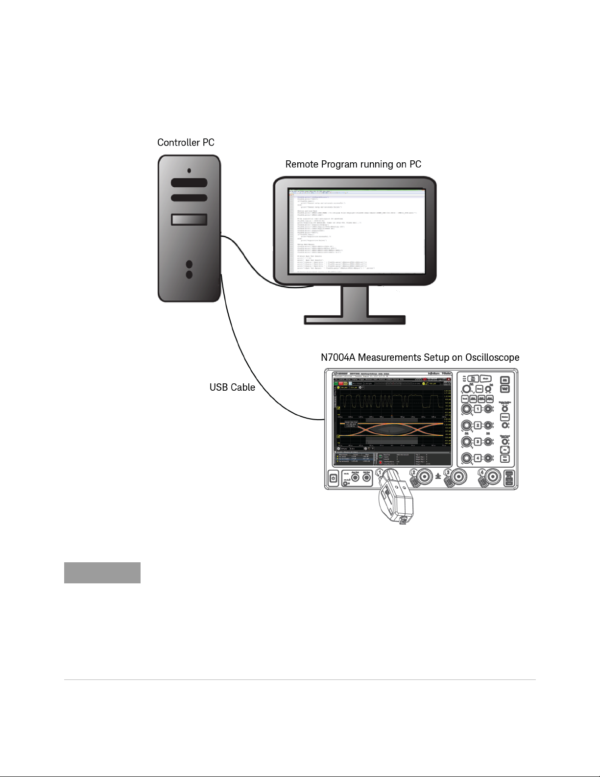
You can use the Remote Programming SCPI commands described in this chapter to remotely control
the oscilloscope from a controller PC for:
• configuring the N7004A setup such as channel's bandwidth limit filter response.
• adding optical measurements and querying for these measurements’ results.
• configuring eye mask testing.
Page 40
4 Remotely Controlling the N7004A Measurement Setup
NOTE
Sample Remote Control Setup of N7004A
Before you can start remotely controlling the N7004A setup using SCPI commands, ensure
that you have:
- installed the Keysight IO Libraries Suite software on the controller PC.
- connected the oscilloscope to the controller PC using USB, LAN, or GPIB.
- verified the oscilloscope connection.
To get detailed information on the above-mentioned points or on basic program
communications, interface, syntax, data types, and status reporting, refer to your
oscilloscope’s Programmer’s Guide.
40 N7004A 33GHz Optical-to-Electrical-Converter User Guide
Page 41

SCPI Commands for Controlling the N7004A Setup
This topic includes only those SCPI commands that are unique to the N7004A scenario. You can find
the complete list of SCPI commands for remotely controlling you oscilloscope in your oscilloscope’s
Programmer’s Guide.
Remotely Controlling the N7004A Measurement Setup 4
N7004A 33GHz Optical-to-Electrical-Converter User Guide 41
Page 42

4 Remotely Controlling the N7004A Measurement Setup
:MEASure:OPOWer
Command Syntax :MEASure:OPOWer [<source>][,{WATT | DBM}]
where:
• <source> can be {CHANnel<N> | DIFF<D> | COMMonmode<C> | FUNCtion<F> | WMEMory<R>
|CLOCk | MTRend | MSPectrum | EQUalized}
• {WATT | DBM} - Specifies the measurement units in Watts or dBm.
Description The :MEASure:OPOWer command installs an Optical Average Power measurement into the user
interface's measurement Results pane.
Optical average power is a measure of the true average component of an optical signal. If markers
are tracking this measurement, the marker is placed on the optical power Watts. This measurement
is commonly used when identifying the fundamental parameters of a lightwave transmitter. However,
it differs from other measurements because it does not rely on the waveform display to determine the
measurement. The analog-to-digital converter is in the probe itself, independent of the waveform
displayed on the screen. You can measure the optical power of an eye diagram.
Query Syntax :MEASure:OPOWer? [<source>][,{WATT | DBM}]
The query returns the measured Optical Average Power.
Query Response
Format
[:MEASure:OPOWer] <value>[,<result_state>]<NL>
where:
• <value> is the measured Optical Average Power value.
• <result_state> - If SENDvalid is ON, the result state is returned with the measurement result. See
the :MEASure:RESults table in your oscilloscope’s programmer’s guide for a list of the result
states.
42 N7004A 33GHz Optical-to-Electrical-Converter User Guide
Page 43

Remotely Controlling the N7004A Measurement Setup 4
:MEASure:CGRade:OLEVel
Command Syntax :MEASure:CGRade:OLEVel [<source>]
where:
• <source> can be {CHANnel<N> | DIFF<D> | COMMonmode<C> | FUNCtion<F> | WMEMory<R>
|CLOCk | MTRend | MSPectrum | EQUalized}
• If <source> is omitted, the Q-factor will be performed on the first waveform that has color grade
enabled.
Description The :MEASure:CGRade:OLEVel command installs an Eye One Level measurement into the user
interface's measurement Results pane. Eye one level is a measure of the mean value of the logical 1
of an eye diagram.
Before using this command or query, you must use the :DISPlay:CGRade command to enable the
color grade persistence feature. Also, there must be a full eye diagram on screen before a valid
measurement can be made.
Query Syntax :MEASure:CGRade:OLEVel? [<source>]
The query returns the measured Eye One Level.
Query Response
Format
[:MEASure:CGRade:OLEVel] <value>[,<result_state>]<NL>
where:
• <value> is the measured Eye One Level value.
• <result_state> - If SENDvalid is ON, the result state is returned with the measurement result. See
the :MEASure:RESults table in your oscilloscope’s programmer’s guide for a list of the result
states.
N7004A 33GHz Optical-to-Electrical-Converter User Guide 43
Page 44

4 Remotely Controlling the N7004A Measurement Setup
:MEASure:CGRade:ZLEVel
Command Syntax :MEASure:CGRade:ZLEVel [<source>]
where:
• <source> can be {CHANnel<N> | DIFF<D> | COMMonmode<C> | FUNCtion<F> | WMEMory<R>
|CLOCk | MTRend | MSPectrum | EQUalized}
• If <source> is omitted, the Q-factor will be performed on the first waveform that has color grade
enabled.
Description The :MEASure:CGRade:ZLEVel command installs an Eye Zero Level measurement into the user
interface's measurement Results pane. Eye zero level is a measure of the mean value of the logical 0
of an eye diagram. Before using this command or query, you must use the :DISPlay:CGRade
command to enable the color grade persistence feature. Also, there must be a full eye diagram on
screen before a valid measurement can be made.
Query Syntax :MEASure:CGRade:ZLEVel? [<source>]
The query returns the measured Eye Zero Level.
Query Response
Format
[:MEASure:CGRade:ZLEVel] <value>[,<result_state>]<NL>
where:
• <value> is the measured Eye Zero Level value.
• <result_state> - If SENDvalid is ON, the result state is returned with the measurement result. See
the :MEASure:RESults table in your oscilloscope’s programmer’s guide for a list of the result
states.
44 N7004A 33GHz Optical-to-Electrical-Converter User Guide
Page 45

Remotely Controlling the N7004A Measurement Setup 4
:MEASure:OMAMplitude
Command Syntax :MEASure:OMAMplitude [<source>][,{WATT | DBM}]
where:
• <source> can be {CHANnel<N> | DIFF<D> | COMMonmode<C> | FUNCtion<F> | WMEMory<R>
|CLOCk | MTRend | MSPectrum | EQUalized}
• {WATT | DBM} Specifies the measurement units in Watts or dBm.
Description The :MEASure:OMAMplitude command installs an Optical Modulation Amplitude (OMA)
measurement into the user interface's measurement Results pane. Optical Modulation Amplitude
(OMA) is the measure of the difference between the optical power of an NRZ (non-return-to-zero)
one pulse and the optical power of an NRZ zero pulse. It requires an NRZ pattern and is designed to
be used with a square wave made of consecutive zeros followed by consecutive ones. Be sure to
check any relevant standard for one and zero run requirements. All instances are measured if
Measure All Edges is selected. Otherwise, the edges closest to the timebase reference are measured.
Query Syntax :MEASure:OMAMplitude? [<source>][,{WATT | DBM}]
The query returns the measured Optical Modulation Amplitude (OMA).
Query Response
Format
[:MEASure:OMAMplitude] <value>[,<result_state>]<NL>
where:
• <value> is the measured Optical Modulation Amplitude (OMA) value.
• <result_state> - If SENDvalid is ON, the result state is returned with the measurement result. See
the :MEASure:RESults table in your oscilloscope’s programmer’s guide for a list of the result
states.
N7004A 33GHz Optical-to-Electrical-Converter User Guide 45
Page 46

4 Remotely Controlling the N7004A Measurement Setup
NOTE
:MEASure:ERATio
Command Syntax :MEASure:ERATio [<source>[,{RATio | DB | PERCent}]]
where:
• <source> can be {CHANnel<N> | DIFF<D> | COMMonmode<C> | FUNCtion<F> | WMEMory<R>
|CLOCk | MTRend | MSPectrum | EQUalized}
• {RATio | DB | PERCent} Specifies the measurement units in Ratio, Decibel, or Percentage.
Description The :MEASure:ERATio command installs an Extinction Ratio measurement into the user
interface's measurement Results pane. Extinction Ratio is the ratio of the one level and the zero level
of an eye diagram of an optical signal.
Query Syntax :MEASure:ERATio? [<source>[,{RATio | DB | PERCent}]]
The query returns the measured extinction ratio.
Query Response
Format
[:MEASure:ERATio] <value>[,<result_state>]<NL>
where:
• <value> is the measured extinction ratio value.
• <result_state> - If SENDvalid is ON, the result state is returned with the measurement result. See
the :MEASure:RESults table in your oscilloscope’s programmer’s guide for a list of the result
states.
The :MEASure:ERATio query returns a ‘?’ on the extinction ratio measurement if:
- The dark calibration has not been performed at all.
- The vertical sensitivity, offset, or sample rate of the oscilloscope has changed since the dark
calibration was run.
- The N7004A’s temperature has changed by > 2
o
C.
46 N7004A 33GHz Optical-to-Electrical-Converter User Guide
Page 47

N7004A 33GHz Optical-to-Electrical-Converter
User Guide
5 Performance Verification for
N7004A
Test Strategy / 48
Test Interval / 48
Test Equipment / 48
Test Procedure / 49
This chapter describes how to verify the bandwidth performance of the N7004A against its
bandwidth specification (as listed on page 9).
The bandwidth performance of N7004A is specified when used with an Infiniium 33 GHz oscilloscope.
The oscilloscope automatically downloads S parameters and calibration data from the N7004A when
you connect the N7004A to one of the oscilloscope’s channels. This adjusts the system response and
allows highly accurate measurements.
Page 48

5 Performance Verification for N7004A
NOTE
Test Strategy
The basic method for verifying the bandwidth of the N7004A is to use a femtosecond pulse laser.
These types of laser sources output a very fast impulse that is much faster than the impulse response
of the N7004A thus allowing measurement of the N7004A bandwidth without de-embedding the
laser impulse response. Verification of the laser source is not considered in this testing but can be
typically verified with an optical sampling scope or other optical methods.
The performance verification testing is also performed at the Keysight Technologies as part of
the return-to-factory recertification to warrant performance.
You can either test the N7004A bandwidth performance using the recommended test
equipment and by following the procedure documented in this chapter. Or you may want to
send your N7004A to the Keysight Technologies to get the bandwidth performance verification
done by specialized Keysight staff.
Test Interval
The Keysight return-to-factory recertification interval to warrant performance of N7004A is 1 year.
However, you can also test the N7004A bandwidth performance as and when required using the
recommended test equipment and by following the procedure documented in this chapter.
Test Equipment
A list of the recommended test equipment is provided. The instructions in this chapter are written
with the presumption that you are using these recommended test equipment. You can substitute
these equipment with equivalent equipment that satisfy the specifications given. However, results
with substituted equipment may or may not yield identical results.
Test Equipment Model #
Calmar femtosecond pulse laser
(Qty 1)
This laser source has two outputs;
• a 1560nm port for testing longer wavelengths (i.e. 1310 and 1550nm)
• a 780nm port for testing shorter wavelengths (i.e. 760 and 850nm)
Keysight Lightwave Multimeter 2 slot mainframe (or other Keysight mainframe with more
slots)
(Qty 1)
Keysight Single Mode optical attenuator module for use in mainframe
(Qty 1)
Keysight Multi Mode optical attenuator module for use in mainframe
(Qty 1)
L-Com 1m single mode FC/FC patch cables (or equivalent)
(Qty 2)
L-Com dual multi-mode FC/FC patch cable (or equivalent) which can be separated into two
single cables for use in this procedure
(Qty 1)
FPL-02RFFAGT12
8163B
81570A
81578A
SFOFC-01
FODFC50-01
48 N7004A 33GHz Optical-to-Electrical-Converter User Guide
Page 49

Test Procedure
CAUTION
CAUTION
NOTE
Performance Verification for N7004A 5
The Calmar pulse laser used in this procedure outputs a large impulse that could damage the
input of the N7004A. As described in the procedure below, set the optical attenuators to
maximum attenuation before enabling the optical attenuators and then lower the attenuation
until a 1.5 to 2mW signal is seen on the oscilloscope’s screen.
Before making the connections between the fiber-optic connectors using a single-mode or a
multi-mode patch cable as described in the procedure below, you must clean the fiber ends of
these connectors and the mating fiber-optic cable or patch cable. To get details on the
cleaning procedure, refer to the topic, “Step 1 - Clean the Fiber-Optic Connectors" on page 14
1 Install 81570A SM attenuator and 81578A MM attenuator in 8163B frame.
2 Turn on Calmar laser (but not the keyed "Pump Laser"), 33GHz Infiniium oscilloscope, and 8163B
frame.
3 Connect N7004A to be tested to channel 1 of the oscilloscope.
4 Let all equipment warm up for 45 minutes.
5 Set both attenuators for the maximum attenuation of 60db.
6 While observing cleaning procedures, connect optical output A (760nm) to the input of the MM
81578A using the multi-mode patch cable.
7 While observing cleaning procedures, connect optical output B (1560nm) to the input of the MM
81570A using the single mode patch cable
8 Perform a default setup on the oscilloscope.
9 While observing cleaning procedures, connect the output of the 81578A to the N7004A using a
multi-mode patch cable.
10 Under Setup Probe Configuration, select Options for the N7004A on channel 1 and select 850nm.
11 Enable the 81578A attenuator by pressing the button on the front of the module. This allows the
laser light through the attenuator.
12 Turn on the keyed Pump Laser on the Calmar laser and adjust the Pump Current to maximum.
13 Set up the oscilloscope as follows:
• Trigger on channel 1, level 500uW
•Timebase to 200pS/div
• Channel 1 to 500uW/div
• In Setup Acquisition, set for average mode with 1024 averages
14 Begin lowering the attenuation on the 81578A until an impulse is seen. Lower it until the
amplitude of the impulse is 1.5 to 2mW.
The Calmar laser may produce a "double” (multiple) pulse when the pump laser is set to
maximum. If it does, then lower the pump laser setting until the "double" pulse stops.
Single pulse outputs are stable with pulses evenly spaced in time. Multiple pulse outputs
have arbitrary time delays between adjacent pulses. For details on single and multiple pulse,
refer to the Calmar user manual.
15 Change the timebase to 2nS/div.
N7004A 33GHz Optical-to-Electrical-Converter User Guide 49
Page 50
5 Performance Verification for N7004A
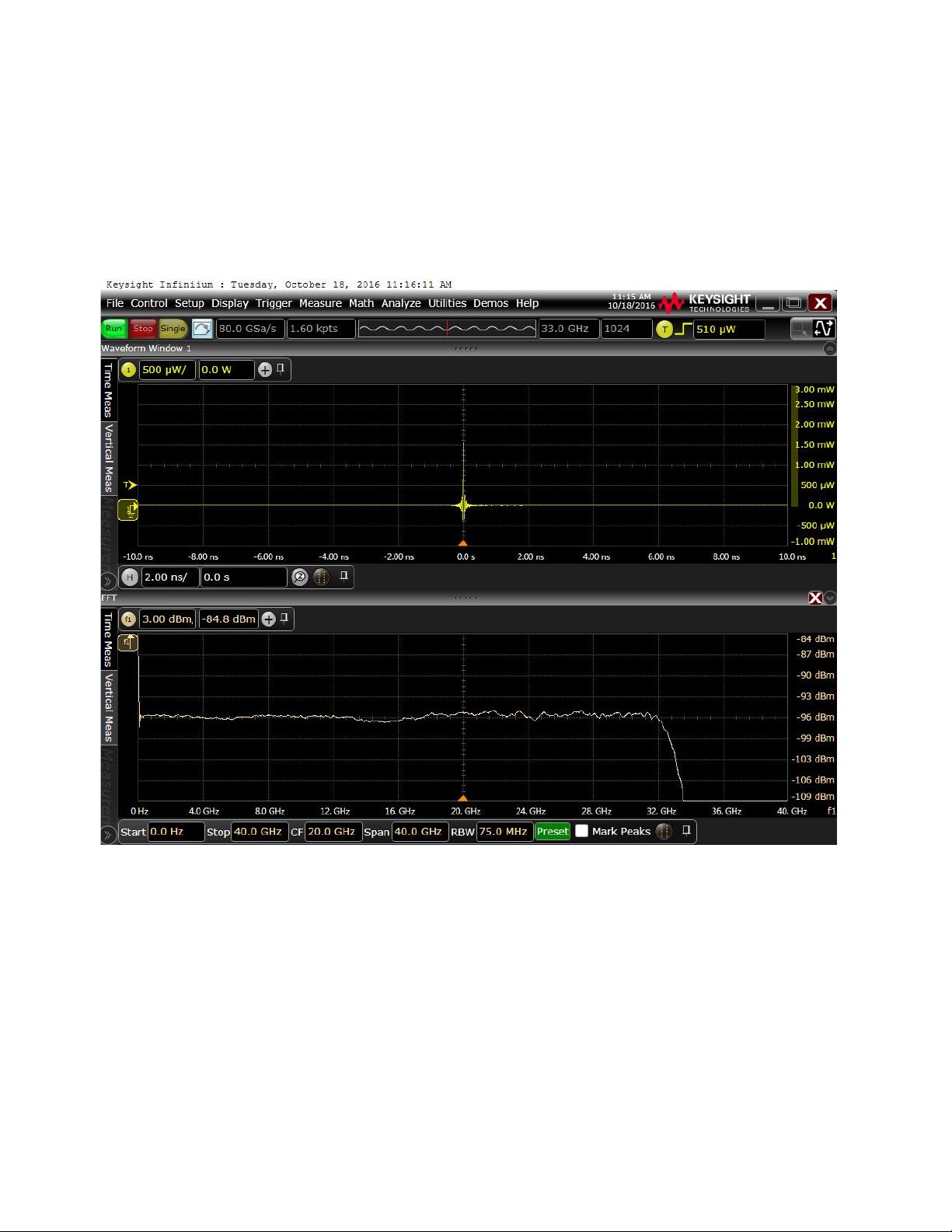
16 Invoke a frequency response (FFT) on channel 1 using Math/New FFT/Channel1 from the pull down
menu.
17 Set the FFT scale to 3db/div and adjust the FFT offset to get the left hand side of the FFT
waveform (0 to 4GHz) at center screen. To do this, grab the FFT waveform with the left mouse
button and move it to center screen. See Figure 2.
Figure 2 Upper trace: N7004A impulse response. Lower trace: FFT of impulse showing bandwidth
Verify that the FFT is not down more than 3db at 32 GHz. For instance, in the sample screen
above, the response is still at 0db at 32 GHz.
18 Disable the 81578A attenuator.
19 While observing cleaning procedures, connect the output of the 81570A to the N7004A using a
single mode patch cable.
20 Under Setup Probe Configuration, select Options for the N7004A on channel 1 and select 1550nm.
21 Enable the 81570A attenuator by pressing the button on the front of the module. This allows the
laser light through the attenuator.
22 Begin lowering the attenuation on the 81570A until an impulse is seen. Lower it until the
amplitude of the impulse is 1.5 to 2mW,
50 N7004A 33GHz Optical-to-Electrical-Converter User Guide
Page 51

Performance Verification for N7004A 5
NOTE
The Calmar laser may produce a "double” (multiple) pulse when the pump laser is set to
maximum. If it does, then lower the pump laser setting until the "double" pulse stops.
Single pulse outputs are stable with pulses evenly spaced in time. Multiple pulse outputs
have arbitrary time delays between adjacent pulses. For details on single and multiple pulse,
refer to the Calmar user manual.
23 If needed, center the FFT waveform as done earlier in this procedure.
Verify that the frequency response (FFT) is not down more than 3db at 32 GHz.
24 Disable the 81570A attenuator.
This completes the bandwidth performance verification testing for N7004A.
N7004A 33GHz Optical-to-Electrical-Converter User Guide 51
Page 52

5 Performance Verification for N7004A
52 N7004A 33GHz Optical-to-Electrical-Converter User Guide
Page 53

N7004A 33GHz Optical-to-Electrical-Converter
User Guide
6 Calibration Strategy
You need to perform dark calibration (see page 28) on N7004A whenever you change the vertical
scale or offset of the oscilloscope.
In addition to performing dark calibration, Keysight recommends that you also get the factory
calibration done once in a year by sending the N7004A to the Keysight Technologies. Factory
calibration also includes bandwidth performance verification testing (see page 47) for N7004A.
Page 54

6 Calibration Strategy
54 N7004A 33GHz Optical-to-Electrical-Converter User Guide
Page 55

N7004A 33GHz Optical-to-Electrical-Converter
User Guide
7 Troubleshooting
This chapter covers some common troubleshooting scenarios that may be relevant for you while
using N7004A.
If the problem persists, contact Keysight Technologies. To locate a sales or a service office near you,
go to www.keysight.com/find/contactus.
The service strategy for the N7004A is to send it to Keysight Technologies for all service work.
Keysight requires that the N7004A unit be repaired only at qualified repair facilities such as the
Keysight Repair Centers.
Problem Possible Cause(s) Solution
Unable to make optical measurements
using N7004A.
The dark calibration failed. Refer to the topic “Reasons for the Failure of the Dark Calibration" on page 30.
Problem in optical signal transmission Low transmitted power Check alignment of the optical cable
Extinction ratio is out of range (that is,
lower than expectations)
The Optical Average Power measurement
displays the value “Responsivity?”
Erratic optical measurements are
displayed.
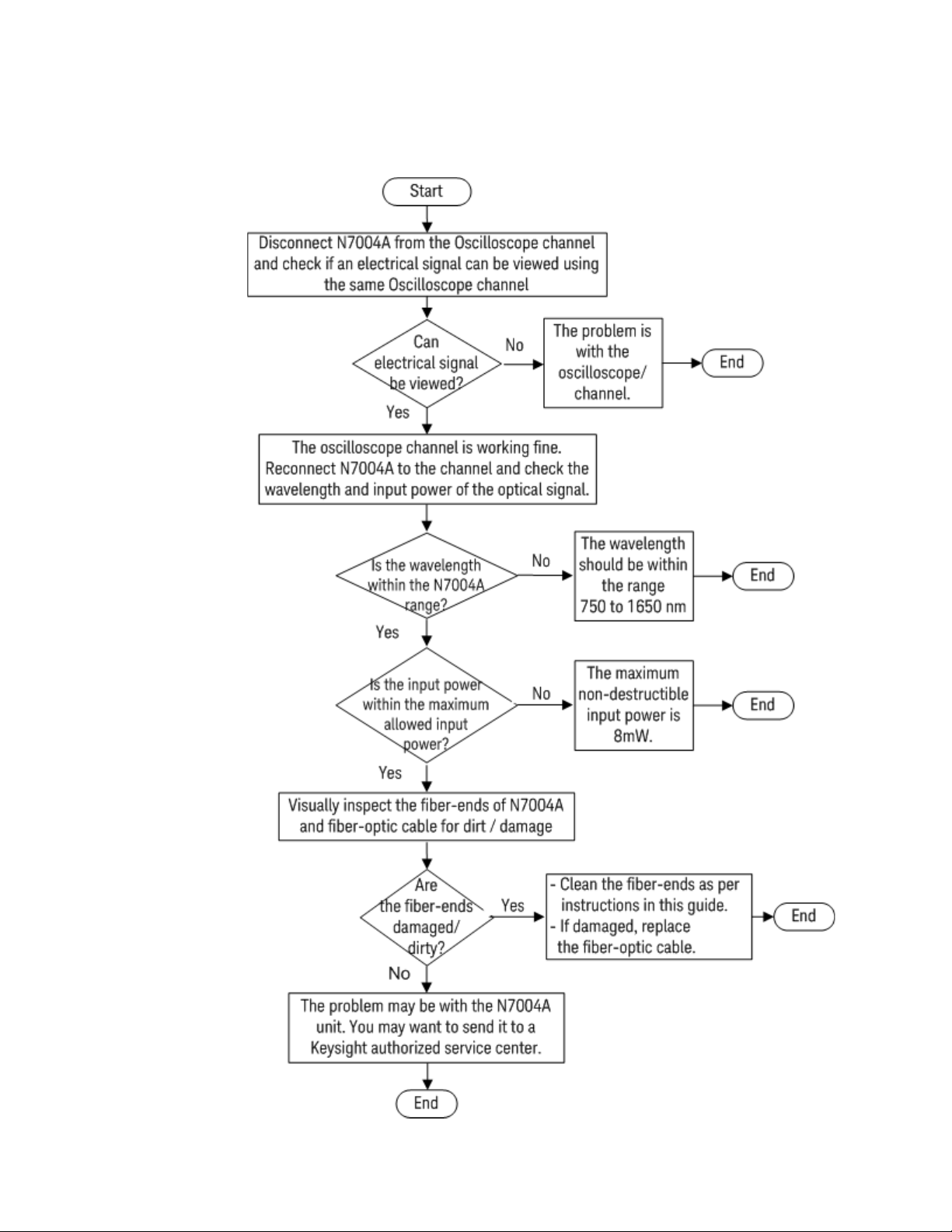
Multiple (as indicated in the flowchart
provided in “Troubleshooting Flowchart
section.)
The optic connector of N7004A or optic
cable is dirty and requires cleaning.
You have selected the User Defined
wavelength option for N7004A.
The optic connector of N7004A or optic
cable is dirty and requires cleaning.
Start at the top of the flowchart
provided in “Troubleshooting Flowchart
section. The flowchart directs you to the
relevant steps.
into N7004A.
Ensure that the keying features of both
the N7004A FC/PC Input connector and
fiber-optic cable’s connector are
aligned properly before you start
finger-tightening the connection.
Refer to the topic “Aligning the Keying
Features while Making the
Connection" on page 19.
Clean the fiber-ends of both N7004A as
well as optic cable’s connectors as per
instructions given in “Step 1 - Clean the
Fiber-Optic Connectors" on page 14.
Manually specify and adjust the
Responsivity value for N7004A.
Refer to the topic “Adjusting Conversion
Gain for a User-defined Wavelength" on
page 22.
Clean the fiber-ends of both N7004A as
well as optic cable’s connectors as per
instructions given in “Step 1 - Clean the
Fiber-Optic Connectors" on page 14.
Page 56
7 Troubleshooting
Troubleshooting Flowchart
56 N7004A 33GHz Optical-to-Electrical-Converter User Guide
Page 57

N7004A 33GHz Optical-to-Electrical-Converter
User Guide
8 Returning the N7004A for Re-
pair or Service
If the N7004A is found to be defective, we recommend sending it to a Keysight authorized service
center for all repair and calibration needs.
Perform the following steps before shipping the N7004A back to Keysight Technologies for repair /
service.
1 Contact your nearest Keysight sales office for any additional details.
2 Write the following information on a tag and attach it to the malfunctioning equipment.
• Name and address of owner
• Product model number (N7004A)
• Product Serial Number (for example, MYXXXXXXXX)
• Description of failure or service required
3 Protect the N7004A by wrapping in plastic or heavy paper. Use original packaging or
comparable.
4 Pack the N7004A in the original carrying case or if not available, use bubble wrap or packing
peanuts.
5 Place securely in sealed shipping container and mark container as "FRAGILE".
If any correspondence is required, refer to the product by serial number and model number.
Contacting Keysight Technologies
For technical assistance, contact your local Keysight Call Center.
• In the Americas, call 1 (800) 829-4444
• In other regions, visit http://www.keysight.com/find/assist
Before returning an instrument for service, you must first call the Call Center.
Page 58

8 Returning the N7004A for Repair or Service
58 N7004A 33GHz Optical-to-Electrical-Converter User Guide
Page 59
N7004A 33GHz Optical-to-Electrical-Converter
WARNING
WARNING
WARNING
CAUTION
CAUTION
User Guide
9 Safety and Regulatory Infor-
mation
This product has been designed and tested in accordance with accepted industry standards, and has
been supplied in a safe condition. The documentation contains information and warnings that must
be followed by the user to ensure safe operation and to maintain the product in a safe condition.
Only Keysight approved accessories shall be used.
If this product is not used as specified, the protection provided by the
equipment could be impaired.
Do not attempt internal service or adjustment. Service should be carried out
by a Keysight Technologies authorized service personnel. For any service
needs, contact Keysight Technologies.
Indoor Use Only. Do not operate in wet / damp environments. Keep product
surfaces dry and clean.
Do not operate in an explosive environment.
The input circuitry of the N7004A can be damaged when total input power
levels exceed 8mW. To prevent damage, this specified level must not be
exceeded.
Damage to the fiber-optic connectors can degrade measurement accuracy
and repeatability and can cause expensive damage to instruments.
To avoid damage to the N7004A’s fiber-optic connector, ensure that you
follow the cleaning techniques and the warnings and cautions included in
the topic “Step 1 - Clean the Fiber-Optic Connectors" on page 14.
Page 60
9 Safety and Regulatory Information
Instrument Markings
Marking Description
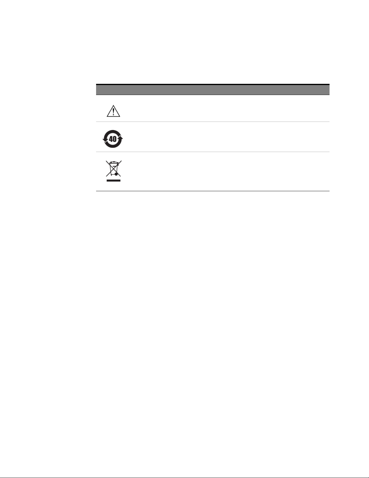
The instruction documentation symbol. The product is marked with this symbol when it is necessary for
the user to refer to the instructions in the documentation to protect against damage to the product or
personal injury.
This symbol indicates the Environmental Protection Use Period (EPUP) for the product’s toxic substances
for the China RoHS requirements.
This product complies with the WEEE Directive (2002/96/EC) marking requirements. The affixed label
indicates that you must not discard this electrical/electronic product in domestic household waste.
Product Category: With reference to the equipment types in the WEEE Directive Annex I, this product is
classed as a “Monitoring and Control instrumentation” product. Do not dispose in domestic household. To
return unwanted products, contact your local Keysight office, or refer to www.keysight.comfor more
information.
60 N7004A 33GHz Optical-to-Electrical-Converter User Guide
Page 61

N7004A 33GHz Optical-to-Electrical-Converter User Guide 61
Page 62

This information is subject to
change without notice.
© Keysight Technologies 2019
Edition 2, April 2019
N7004-92000
www.keysight.com
 Loading...