


Keysight N5991MC2A MIPI
®
C-PHY
Test Automation
Software Platform
User Guide

Notices
CAUTION
WARNING
© Keysight Technologies 2021
No part of this manual may be reproduced
in any form or by any means (including
electronic storage and retrieval or translation into a foreign language) without prior
agreement and written consent from
Keysight Technologies as governed by
United States and international copyright
laws.
Trademarks
MIPI® C-PHY™ is a registered trademark of
the MIPI Alliance.
Manual Part Number
N5991-91700
Edition
Edition 2.0, Jan 2021
Keysight Technologies Deutschland GmbH
Herrenberger Strasse 130,
71034 Böblingen, Germany
Technology Licenses
The hardware and/or software described in
this document are furnished under a
license and may be used or copied only in
accordance with the terms of such license.
U.S. Government Rights
The Software is “commercial computer
software,” as defined by Federal Acquisition
Regulation (“FAR”) 2.101. Pursuant to FAR
12.212 and 27.405-3 and Department of
Defense FAR Supplement
(“DFARS”) 227.7202, the U.S. government
acquires commercial computer software
under the same terms by which the software is customarily provided to the public.
Accordingly, Keysight provides the Software to U.S. government customers under
its standard commercial license, which is
embodied in its End User License Agree-
ment (EULA), a copy of which can be found
at http://www.keysight.com/find/sweula.
The license set forth in the EULA represents
the exclusive authority by which the U.S.
government may use, modify, distribute, or
disclose the Software. The EULA and the
license set forth therein, does not require
or permit, among other things, that Keysight: (1) Furnish technical information
related to commercial computer software
or commercial computer software documentation that is not customarily provided
to the public; or (2) Relinquish to, or otherwise provide, the government rights in
excess of these rights customarily provided
to the public to use, modify, reproduce,
release, perform, display, or disclose commercial computer software or commercial
computer software documentation. No
additional government requirements
beyond those set forth in the EULA shall
apply, except to the extent that those
terms, rights, or licenses are explicitly
required from all providers of commercial
computer software pursuant to the FAR and
the DFARS and are set forth specifically in
writing elsewhere in the EULA. Keysight
shall be under no obligation to update,
revise or otherwise modify the Software.
With respect to any technical data as
defined by FAR 2.101, pursuant to FAR
12.211 and 27.404.2 and DFARS 227.7102,
the U.S. government acquires no greater
than Limited Rights as defined in FAR
27.401 or DFAR 227.7103-5 (c), as applicable in any technical data.
Warranty
THE MATERIAL CONTAINED IN THIS
DOCUMENT IS PROVIDED "AS IS," AND IS
SUBJECT TO BEING CHANGED, WITHOUT
NOTICE, IN FUTURE EDITIONS. FURTHER,
TO THE MAXIMUM EXTENT PERMITTED BY
APPLICABLE LAW, KEYSIGHT DISCLAIMS
ALL WARRANTIES, EITHER EXPRESS OR
IMPLIED WITH REGARD TO THIS MANUAL
AND ANY INFORMATION CONTAINED
HEREIN, INCLUDING BUT NOT LIMITED TO
THE IMPLIED WARRANTIES OF
MERCHANTABILITY AND FITNESS FOR A
PARTICULAR PURPOSE. KEYSIGHT SHALL
NOT BE LIABLE FOR ERRORS OR FOR
INCIDENTAL OR CONSEQUENTIAL
DAMAGES IN CONNECTION WITH THE
FURNISHING, USE, OR PERFORMANCE OF
THIS DOCUMENT OR ANY INFORMATION
CONTAINED HEREIN. SHOULD KEYSIGHT
AND THE USER HAVE A SEPARATE
WRITTEN AGREEMENT WITH WARRANTY
TERMS COVERING THE MATERIAL IN THIS
DOCUMENT THAT CONFLICT WITH THESE
TERMS, THE WARRANTY TERMS IN THE
SEPARATE AGREEMENT WILL CONTROL.
Safety Notices
A CAUTION notice denotes a hazard. It
calls attention to an operating procedure, practice, or the like that, if not
correctly performed or adhered to,
could result in damage to the product
or loss of important data. Do not proceed beyond a CAUTION notice until
the indicated conditions are fully
understood and met.
A WARNING notice denotes a hazard. It
calls attention to an operating procedure, practice, or the like that, if not
correctly performed or adhered to,
could result in personal injury or death.
Do not proceed beyond a WARNING
notice until the indicated conditions
are fully understood and met.
2 Keysight N5991MC2A MIPI® C-PHY Test Automation Software Platform User Guide

Contents
1 Introduction
2 ValiFrame MIPI® C-PHY Station
3 Using the Software
Overview 8
Document History 9
First Edition (May 2020) 9
ValiFrame MIPI® C-PHY Station Configuration 12
Test Station Selection 12
Test Station Configuration 14
Test Instrument Configuration 15
Using Keysight IO VISA Connection Expert 17
®
Starting the MIPI
Configuring DUT 21
Parameters in Configure DUT 22
C-PHY Station 19
Introduction 30
Selecting, Modifying & Running Tests 32
Results 34
®
C-PHY Parameters 36
MIPI
Sequencer Parameters 36
Common Parameters 37
Procedure Parameters 39
Keysight N5991MC2A MIPI® C-PHY Test Automation Software Platform User Guide 3

Contents
4 MIPI® C-PHY Calibrations
Calibration Procedures 42
Overview 42
In System Calibration 43
Skew Calibration 46
Inter Module Skew Calibration 49
Amplifier Level Calibration 51
LP Level Calibration 57
HS Level Calibration 63
TRTF Calibration 66
DCD Calibration 70
Eye Opening Calibration 74
UI Jitter Calibration 79
5 MIPI® C-PHY Source Tests
Overview 84
HS Tests 85
Test 2.3.1 Amplitude Tolerance 85
Test 2.3.2 V_IDTH and V_IDTL Sensitivity (Informative) 88
Test 2.3.3 Jitter Tolerance 91
Test 2.3.4 UI Jitter Tolerance 95
Test 2.4.2 T_HS-Prepare 98
Test 2.4.3 T_HS-PreBegin 102
Test 2.4.4 T_HS-ProgSeq 106
Test 2.4.5 T_HS-Post 109
Semi-Automatic Tests 112
Test 2.4.1 Data 0 Lane T_HS-TERM-EN 112
4 Keysight N5991MC2A MIPI® C-PHY Test Automation Software Platform User Guide

LP Tests 115
Test 2.1.1 V_IH Sensitivity 115
Test 2.1.2 V_IL Sensitivity 118
Test 2.1.3b V_HYST Sensitivity Dynamic 121
Test 2.1.3 V_HYST Sensitivity Static 124
Test 2.1.4 LP-RX Minimum Pulse Width Response 127
Behavioral Tests 130
Test 2.2.1 Init Period TINIT 130
Test 2.2.2 ULPS Exit TWAKEUP 133
Test 2.2.3 Invalid or Aborted Escape Entry 137
Test 2.2.4 Invalid or Aborted Escape Command 140
Test 2.2.5 Post-Trigger Command 144
Test 2.2.6 Data Lane LP-RX Escape Mode Unsupported or Unassigned
Commands
147
Manual Tests 151
Setup Procedure Full 151
Contents
Keysight N5991MC2A MIPI® C-PHY Test Automation Software Platform User Guide 5

Contents
6 Keysight N5991MC2A MIPI® C-PHY Test Automation Software Platform User Guide

Keysight N5991MC2A MIPI® C-PHY Test Automation
Software Platform
User Guide
1 Introduction
Overview / 8
Document History / 9

1 Introduction
Overview
This guide provides a detailed description of the Keysight N5991 MIPI
C-PHY Test Automation Software Platform.
The BitifEye “ValiFrame” Test Automation software is globally marketed
and supported by Keysight Technologies as N5991. This document
describes the calibrations and test procedures conducted by N5991
ValiFrame for MIPI
The N59 91 Valiframe M IP I
conditions and controls all test electronic equipment for automated
receiver tolerance tests. The receiver tests described in this document are
implemented according to the requirements of the Conformance Test
Specification (CTS) and also offers some custom characterization tests to
provide more details on DUT behavior beyond the limits.
The N5991 MIPI
M8195A AWG (Arbitrary Waveform Generator) that allows multi-lane
testing. An Infiniium oscilloscope is also required with these procedures.
®
C-PHY in detail.
®
C-PHY s oftware calibra tes the stress
®
C-PHY Receiver tests support the Keysight Technologies
®
8 Keysight N5991MC2A MIPI® C-PHY Test Automation Software Platform User Guide

Document History
First Edition (May 2020)
Introduction 1
The first edition of this user guide describes functionality of software
version N5991 ValiFrame MIPI
Base specification.
Second Edition (Jan 2021)
The second edition of this user guide describes functionality of software
version N5991 ValiFrame MIPI
Base specification.
®
C-PHY_1.0.0 based on the MIPI® C-PHY
®
C-PHY_1.1.0 based on the MIPI® C-PHY
Keysight N5991MC2A MIPI® C-PHY Test Automation Software Platform User Guide 9

1 Introduction
10 Keysight N5991MC2A MIPI® C-PHY Test Automation Software Platform User Guide

Keysight N5991MC2A MIPI® C-PHY Test Automation
Software Platform
User Guide
2 ValiFrame MIPI®
C-PHY Station
ValiFrame MIPI® C-PHY Station Configuration / 12
Starting the MIPI
After the software has been installed, two icons are added to the desktop
as shown in Figure 1 and Figure 6. The first icon pertains to the Station
Configuration and the other icon pertains to ValiFrame MIPI
®
C-PHY Station / 19
®
C-PHY.

2 ValiFrame MIPI® C-PHY Station
ValiFrame MIPI® C-PHY Station Configuration
Test Station Selection
The set of test instruments that are used for a specific application are
referred to in the following as “Test Station” or in short “Station”. The test
station is controlled by a suitable PC and the N5991 Test Automation
Software Platform.
The ValiFrame MIPI
launching ValiFrame. Double-click the icon (see Figure 1) to launch the
software. Alternatively, to access the ValiFrame Station Configuration on a
Windows-based PC:
Click Start > BitifEye C-PHY N5991 > C-PHY Station Configurator
(N5991).
®
C-PHY Station Configuration must be started prior to
12 Keysight N5991MC2A MIPI® C-PHY Test Automation Software Platform User Guide
Figure 1 Icon for MIPI® C-PHY Station Configurator
The Station Configurator window appears. See Figure 2.
Currently, there is only one test station MIPI C-PHY available in the Select
Station drop-down box.
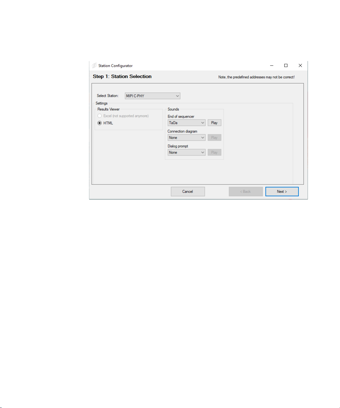
ValiFrame MIPI® C-PHY Station 2
Figure 2 Station Selection stage
Next, you may optionally assign Sounds that would mark the attainment
of different states of the program.
1 End of Sequencer plays the selected sound at the end of a sequence.
2 Connection diagram plays the selected sound every time a connection
diagram pops up.
3 Dialog prompt plays the selected sound at each dialog prompt.
Select a sound tone from the following options available in the drop-down
options. The option ‘None’ disables the sound for the respective action.
• Car brake
• Feep Feep
• Ringing
• TaDa
• Tut
Click “Play” to test a sound before assigning it to a specific action.
After configuring the Station Selection stage, click Next.
Keysight N5991MC2A MIPI® C-PHY Test Automation Software Platform User Guide 13
2 ValiFrame MIPI® C-PHY Station
Test Station Configuration
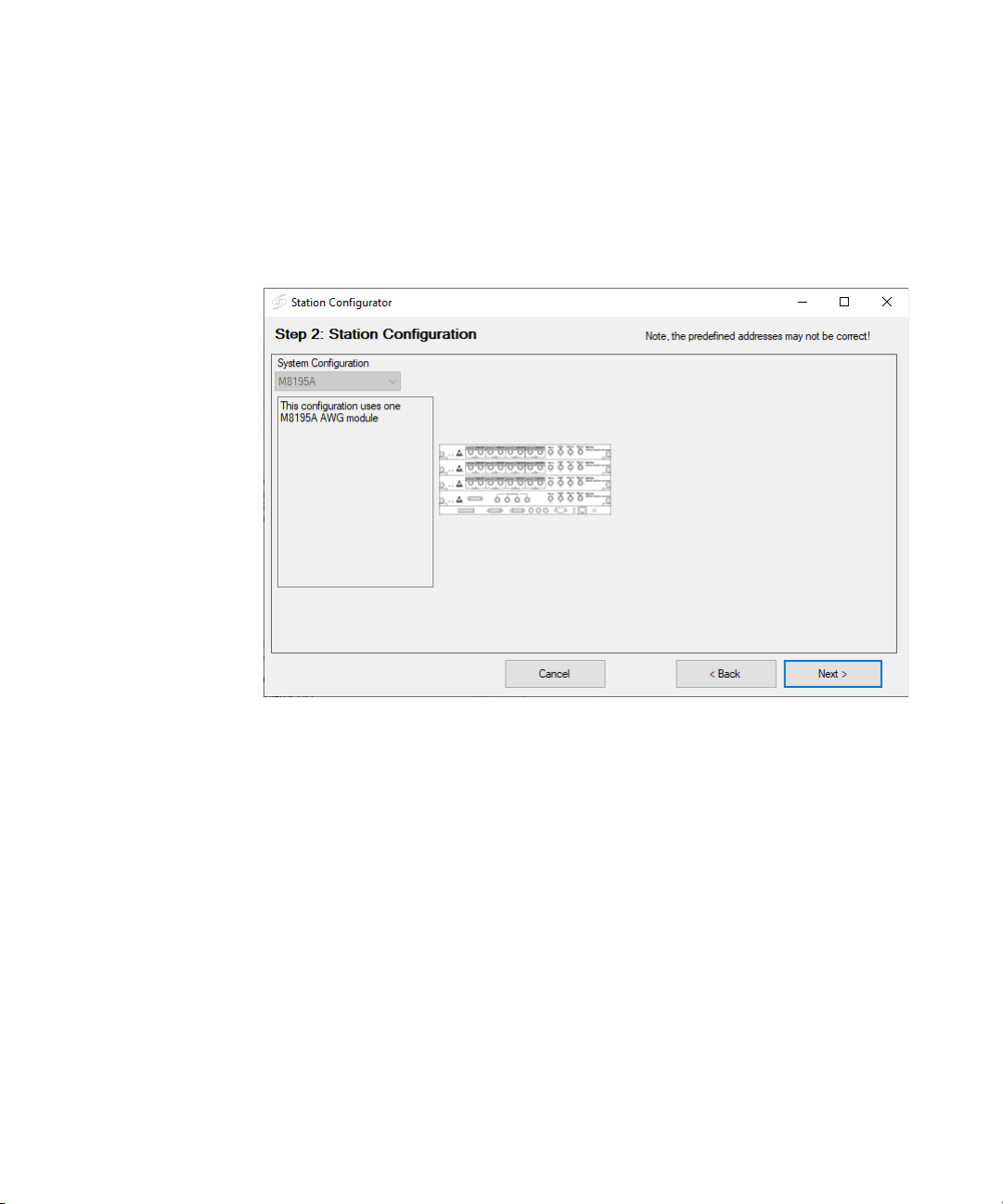
The Station Configuration stage of the Station Configurator is displayed.
See Figure 3. This stage shows instrument options that can be used for
®
MIPI
C-PHY receiver testing.
Figure 3 Station Configuration stage
System Configuration
This drop down field consists of options for MIPI® C-PHY signal
generators.
• M8195A—This option indicates that the M8195A AWG modules are
used for C-PHY output. For more than one AWG module, the M8197A
is used to synchronize the M8195A modules. It supports up to three
Data Lanes.
Once the Station Configuration stage is complete, click Next.
14 Keysight N5991MC2A MIPI® C-PHY Test Automation Software Platform User Guide
Test Instrument Configuration
NOTE
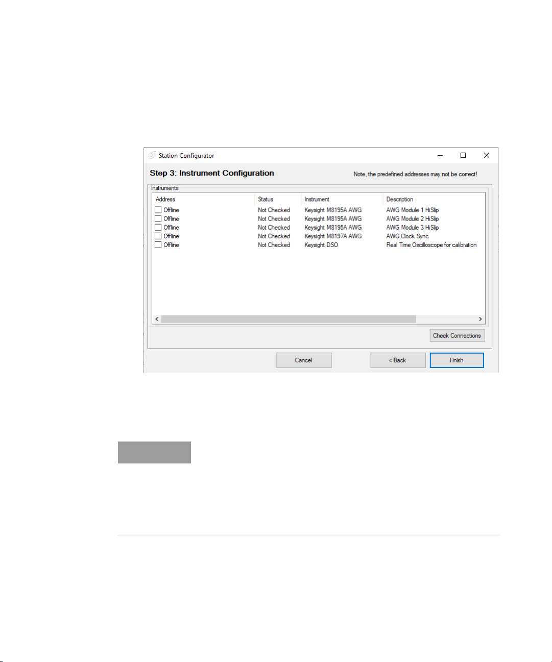
The Instrument Configuration stage of the Station Configurator is
displayed. See Figure 4.
ValiFrame MIPI® C-PHY Station 2
Figure 4 Instrument configuration window
After the installation process, all instruments are configured by default in
Offline mode.
Make sure that all the selected instruments for the test station are
connected to the test station PC controller by the remote control
interfaces, such as LAN or USB. When starting a specific test station
configuration for the first time, all instruments are set to the
Offline
mode. In this mode, the test automation software does not connect to
any instrument. This mode can be used for demonstrations or checks
only.
In the simulation mode, the hardware need not necessarily be physically
connected to the test controller PC. The ValiFrame software cannot
connect to any instrument in this mode. In order to control the instruments
Keysight N5991MC2A MIPI® C-PHY Test Automation Software Platform User Guide 15

2 ValiFrame MIPI® C-PHY Station
that are connected to the PC, the instrument address must be entered.
The address depends on the bus type used for the connection, for
example, GPIB (General Purpose Interface BUS) or LAN (Local Area
Network). Most of the instruments used in the MIPI
a VISA (Virtual Instrument System Architecture) connection. To determine
the VISA address, run the Connection Expert (right-click the Keysight IO
Control icon in the task bar and select the first entry Connection Expert).
Copy the address string for each instrument from the Connection Expert
entries and paste it as the instrument address in the Station Configurator
window. Refer to “Using Keysight IO VISA Connection Expert” on page 17
for more information.
As mentioned earlier, the check boxes are clear and the status of each
instrument is Offline. If you select one or more of these check boxes, a
default address string appears for each selected entry. This address string
is editable. You may either type or paste the correct address string, which
you obtain from the Connection Expert. Click Check Connections to verify
that the instruments are online and the connections for the instruments
are established properly. If an erroneous instrument address configuration
is performed, the Station Configurator displays a prompt to indicate so.
Once the configuration of the Instrument Configuration stage is complete,
click Finish.
®
C-PHY station require
16 Keysight N5991MC2A MIPI® C-PHY Test Automation Software Platform User Guide
Next, you must launch the C-PHY ValiFrame (N5991) software to proceed
with the configuration for MIPI
the MIPI
®
C-PHY Station” on page 19 for more information.
®
C-PHY receiver testing. Refer to “Starting
Using Keysight IO VISA Connection Expert
Introduction
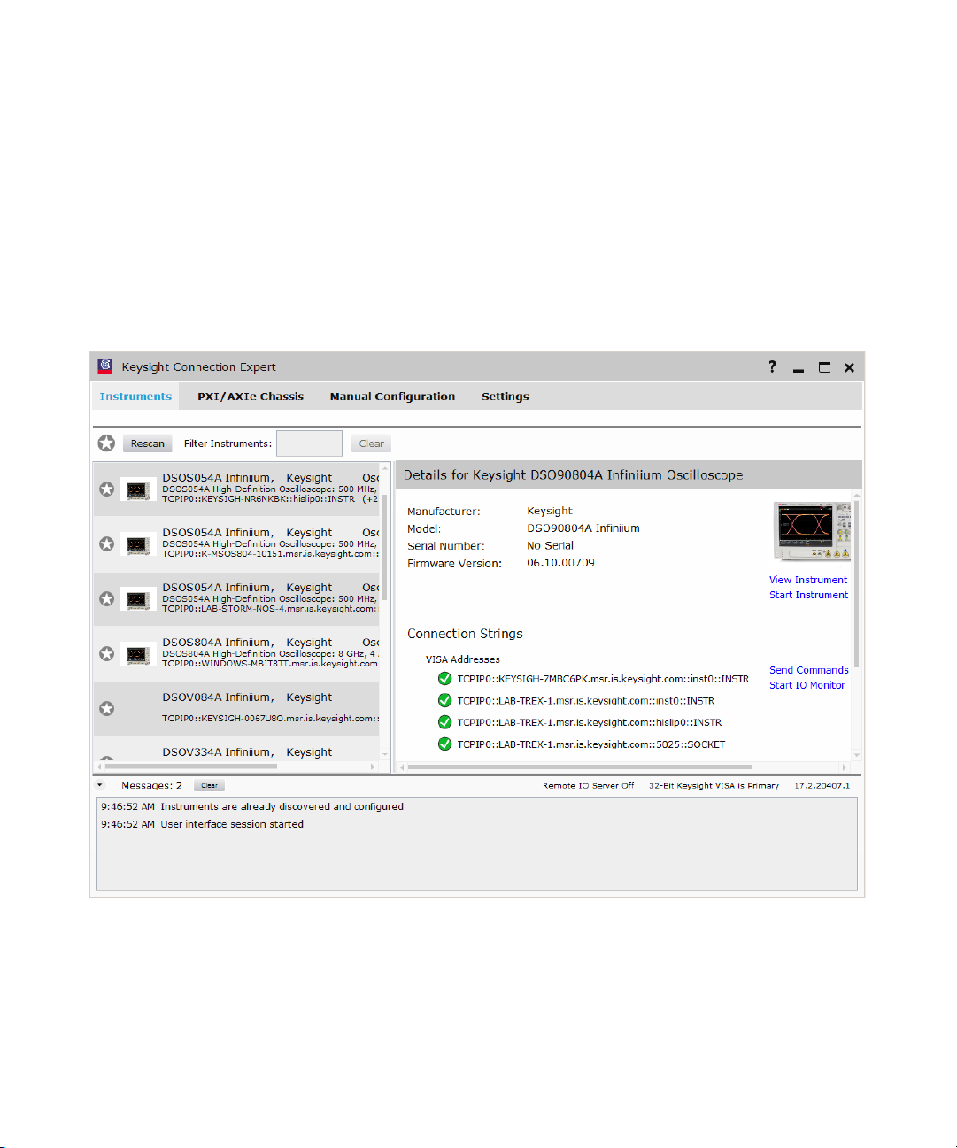
The Keysight Connection Expert is recommended to setup new
connections or verify existing connections. Start the Connection Expert by
right-clicking on the Keysight IO Libraries Suite icon in the task bar and
selecting Connection Expert. A window similar to the one shown in
Figure 5 is displayed.
ValiFrame MIPI® C-PHY Station 2
Figure 5 Keysight Connection Expert
Under “Instruments”, click Rescan.
Keysight N5991MC2A MIPI® C-PHY Test Automation Software Platform User Guide 17

2 ValiFrame MIPI® C-PHY Station
For each instrument that must be connected, verify that the corresponding
information is listed on the menu to the left and that the VISA Address for
each instrument shows a green tick.
Once all the instruments to be used are listed properly, their address
strings can be entered in the Instrument Configuration stage of the
Station Configurator (see Figure 4). The recommended way of doing this is
to copy and paste each instrument address as follows:
Click the “VISA Address” field next to an instrument in the Connection
Expert and copy the address. Highlight the corresponding entry of that
instrument in the Test Station Connection window, paste the address in
the “Instrument Address” text field and click “Apply Address”. Repeat this
procedure for all the instruments being used, except standard specific
applications running on the oscilloscope.
The applications running on the Oscilloscope use a different technology to
provide remote access to ValiFrame, called .NET Remoting
Communication. The remote access is only possible using a LAN
connection to the oscilloscope; therefore, only an IP address is used to
connect to such an instrument.
Once all the instruments are set with the appropriate addresses, tick the
check boxes for all such instruments, which shall be used by the Test
Automation Software. This will set the instrument mode to “Online”. Click
“Check Connections” to verify that the instrument addresses are valid.
Click “Finish” to save the changes and close the ValiFrame Configuration
Wizard.
18 Keysight N5991MC2A MIPI® C-PHY Test Automation Software Platform User Guide

Starting the MIPI® C-PHY Station
Start the ValiFrame MIPI® C-PHY software by double-clicking “C-PHY
Valiframe (N5991)” shortcut icon on the desktop as shown in Figure 6.
Alternatively, click Start > BitifEye C-PHY N5991 > C-PHY ValiFrame
(N5991).
Figure 6 MIPI® C-PHY Valiframe Test Station icon
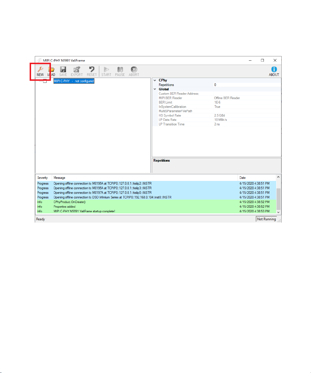
The MIPI C-PHY N5991 Valiframe window appears, as shown in Figure 7.
The ValiFrame N5991 software connects automatically to the instruments,
which are set to online mode in the Instrument Configuration stage (see
Figure 4). The application is ready for use once all the connections have
been initialized successfully.
ValiFrame MIPI® C-PHY Station 2
Keysight N5991MC2A MIPI® C-PHY Test Automation Software Platform User Guide 19
2 ValiFrame MIPI® C-PHY Station
Figure 7 ValiFrame MIPI® C-PHY user interface
The test parameters must be configured before running any test or
calibration procedure. Click the NEW button to launch the Configure DUT
window (Figure 8).
20 Keysight N5991MC2A MIPI® C-PHY Test Automation Software Platform User Guide
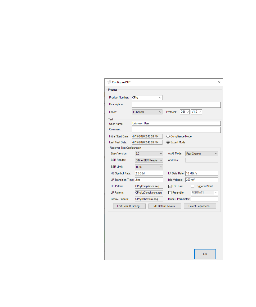
Configuring DUT
ValiFrame MIPI® C-PHY Station 2
The Configure DUT window allows you to select DUT parameters such as
Protocol, Channels and also the parameters related to the Receiver
configuration These parameters shall be used later in several calibrations
and test procedures.
Figure 8 Configure DUT panel
Keysight N5991MC2A MIPI® C-PHY Test Automation Software Platform User Guide 21

2 ValiFrame MIPI® C-PHY Station
Parameters in Configure DUT
The description for parameters that appear in the Configure DUT window
are:
Product
• Product Number—Name that is used to identify the product.
• Description—Text field to describe the product.
• Lanes—Depending on the number of M8195A modules being used, you
may select up to 3 Channels.
• Protocol—Select either CSI (Camera Serial Interface) or DSI (Display
Serial Interface). The receiver tests are performed for MIPI
sequences for the selected protocol. For DSI protocol, you may choose
version as either V1.0 or V1.1. The difference between both DSI
versions is that the sequence structure of “DSI V1.0” contains an ‘SSS’
block.
Test Parameters
• User Name—User name text field.
• Comment—Text field for user comments.
• Initial Start Date—Time stamp of the start of the current session..
• Last Test Date—Time stamp of the last test conducted in the current
session.
• Compliance Mode—Test are conducted as mandated by the CTS. The
parameters that are shown in the calibrations and test procedures
cannot be modified by the user.
• Expert Mode—Calibration and tests can be conducted beyond the limits
and constrains of the CTS. The parameters that are shown in the
calibrations and test procedures can be modified by the user.
®
C-PHY
22 Keysight N5991MC2A MIPI® C-PHY Test Automation Software Platform User Guide
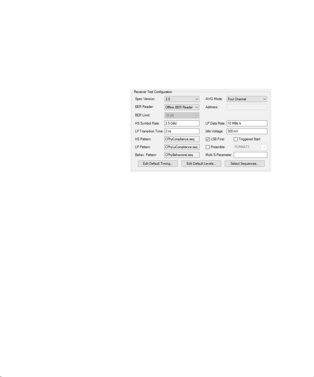
Receiver Test Configuration Parameters
This section contains the parameters required to configure the receiver
tests. A sample configuration of the associated parameters is displayed in
Figure 9.
Figure 9 Sample parameter setup for Receiver Test Configuration
• Spec Version—Refers to the version of the MIPI® Alliance Specification
for C-PHY, that defines the corresponding values for the parameters.
This software covers the MIPI
• AWG Mode—Select one of the options listed below:
• Dual Channel: Only two channels of each M8195A module can be
used. You may test only up to two lanes. The maximum HS symbol
rate allowed for this setup is 4.5GBd.
• Four Channel: The four channels of each M8195A module can be
used. You may test up to three lanes. The maximum HS symbol rate
allowed for this setup is 9GBd.
• BER Reader—For automated receiver testing, it is necessary to
determine whether the DUT receives the data properly. This can be
achieved by measuring and reading the Bit Error Rate (BER) of the DUT.
There two possible methods available:
ValiFrame MIPI® C-PHY Station 2
®
C-PHY spec version 2.0.
Keysight N5991MC2A MIPI® C-PHY Test Automation Software Platform User Guide 23

2 ValiFrame MIPI® C-PHY Station
• Offline BER Reader: This is the default option and does not require
any address for connection. Using this method, the ValiFrame
software shows pop-up dialogs prompting you to reset and initialize
the DUT and it also decides whether the DUT is working properly.
This method is applicable to any DUT that allows a visual check
such as, a Digital Serial Interface device connected to a display, if
the output data is valid with help of a serial decoder. Using an offline
BER reader results in a semi-automated test as, at each test point,
you must click Yes/No prompts to indicate the Pass/Fail information.
• iBERreader: This option enables the custom BER reader. The usage
of a “Custom BER Reader” enables fully automated testing for all
transmission modes (HS and LP). This method requires you to
implement a class supporting the IBerReader interface, providing
access to the DUT’s pass/fail information.
• Address—Provide BER Reader address in this field after selecting
iBEReader.
• BER Limit—Select the BER limit for the tests.
• HS Symbol Rate—Defines the high speed symbol rate for the data
signal.
• LP Data Rate—Defines the low power data rate for the data signal.
• LP Transition Time—Defines the low power transition time for the data
signal.
• Idle Voltage—Sets the offset on the AWG output amplifiers. This is the
output offset voltage when the AWGs are in the ‘Stop’ state.
• HS Pattern—Pattern used for high speed data signal tests. Click the
Select Sequences... button to edit this parameter (refer to Figure 12).
• LP Pattern—Pattern used for low power signal tests. Click the Select
Sequences... button to edit this parameter (refer to Figure 12).
• Behav. Pattern—Pattern used for behavioral tests. Click the Select
Sequences... button to edit this parameter (refer to Figure 12).
• LSB First—The transmission mode of HS Data can be set as ‘LSB’ (Least
Significant Bit) or ‘MSB’ (Most Significant Bit). Select this check box to
use LSB first.
• Triggered Start—Select this check box to trigger the LP-111 sequence
in the signal.
• Preamble—Select this check box to enable calibration preamble in the
sequence. Calibration preamble shall have one of three possible
formats.
• Multi S-Parameter—Together with the In System Calibration
application, the S-Parameters can be provided to de-embed the
system.
24 Keysight N5991MC2A MIPI® C-PHY Test Automation Software Platform User Guide
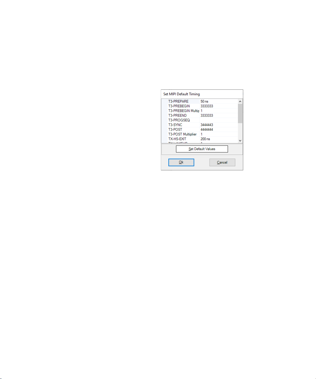
Editing Default Timing Parameters
ValiFrame MIPI® C-PHY Station 2
On the Configure DUT panel, click the Edit Default Timing... button to edit
various MIPI
®
C-PHY timing parameters. The Set MIPI Default Timing
window is displayed in Figure 10.
Figure 10 Set MIPI Default Timing window
• T3-PREPARE—Sets the time that the transmitter drives an LP-000 state
immediately before the start of high speed transmission.
• T3-PREBEGIN—Sets the T3-PREBEGIN pattern in a high-speed MIPI
®
C-PHY pattern format. It should be a multiple of 7 UI from a minimum
of 7UI to 448 UI.
• T3-PREBEGIN Multiplier—Defines a multiplier value between 1 and 64
to set the required HS pattern length from 7UI to 448UI. By default, the
multiplier is set to 1, which indicates that a T3-PREBEGIN pattern
length of (1 x 7UI) 7UI is defined. You may modify the multiplier value
up to 64 to achieve the maximum T3-PREBEGIN pattern length of up to
448UI.
• T3-PREEND—Sets the T3-PREEND pattern in high-speed MIPI
®
C-PHY
pattern format. By default, this pattern contains a total of 7 symbols of
type ‘3’.
• T3-PROGSEQ—Sets the optional T3-PROGSEQ pattern in high-speed
®
MIPI
C-PHY pattern format.
• T3-SYNC—Sets the T3-SYNC, which is sent immediately before starting
high-speed transmission. By default, the pattern is ‘3444443’.
• T3-POST—Sets the T3_POST pattern, which is sent immediately after
starting high-speed transmission.
Keysight N5991MC2A MIPI® C-PHY Test Automation Software Platform User Guide 25

2 ValiFrame MIPI® C-PHY Station
• T3-POST Multiplier—Defines a multiplier value between 1 and 32 to set
the required T3-POST pattern length from 7UI to 224UI. By default, the
multiplier is set to 1, which indicates that a T3-POST pattern length of
(1 x 7UI) 7UI is defined. You may modify the multiplier value up to 32 to
achieve the maximum T3-POST pattern length of up to 224UI.
• TX-HS-EXIT—Sets the length of LP-111 state following a high-speed
burst.
• TX-WAKEUP—Sets the time that the transmitter drives a Mark-1 state
prior to a ‘Stop’ state to initiate exit from the ULPS.
• TX-INIT—Sets the time that the transmitter drives a Stop State
(LP-111).
• T3-CALPREAMBLE—Sets the length of preamble symbol sequence that
consists of a sequence of “1” symbols. It is adjustable in the Transmitter
in increments of seven unit intervals (UI) ranging from a minimum of
one group of seven UI to a maximum of 256 groups of seven UI.
• T3-ASID—Sets the Alternate sequence identifier, which is a sequence of
seven “3” symbols. The purpose of this field is to inform the Receiver
about the Alternate Sequence field that follows. The length of this field
is fixed at 7 UI.
• T3-CALALTSEQ—Sets the Alternate Sequence field that consists of
mapped and encoded PRBS9 data. The length of this field is adjustable
in the transmitter in increments of seven unit intervals (UI) with a range
from a minimum of one group of seven UI to a maximum of 2048 groups
of seven UI.
• T3-UDID—Sets the User-defined sequence identifier, which is a unique
sequence of seven symbols 3333313. The length of this field is fixed at
7 UI.
• T3-CALUDEFSEQ—Sets the User-defined sequence field that consists
of a user-defined sequence of symbols. The length of this field shall be
adjustable in the Transmitter in increments of seven unit intervals (UI)
with a range from a minimum of one group of seven UI to a maximum of
2048 groups of seven UI.
Click Set Default Values button to reset the timing settings to the default
values.
Click OK to return to the Configure DUT panel.
26 Keysight N5991MC2A MIPI® C-PHY Test Automation Software Platform User Guide
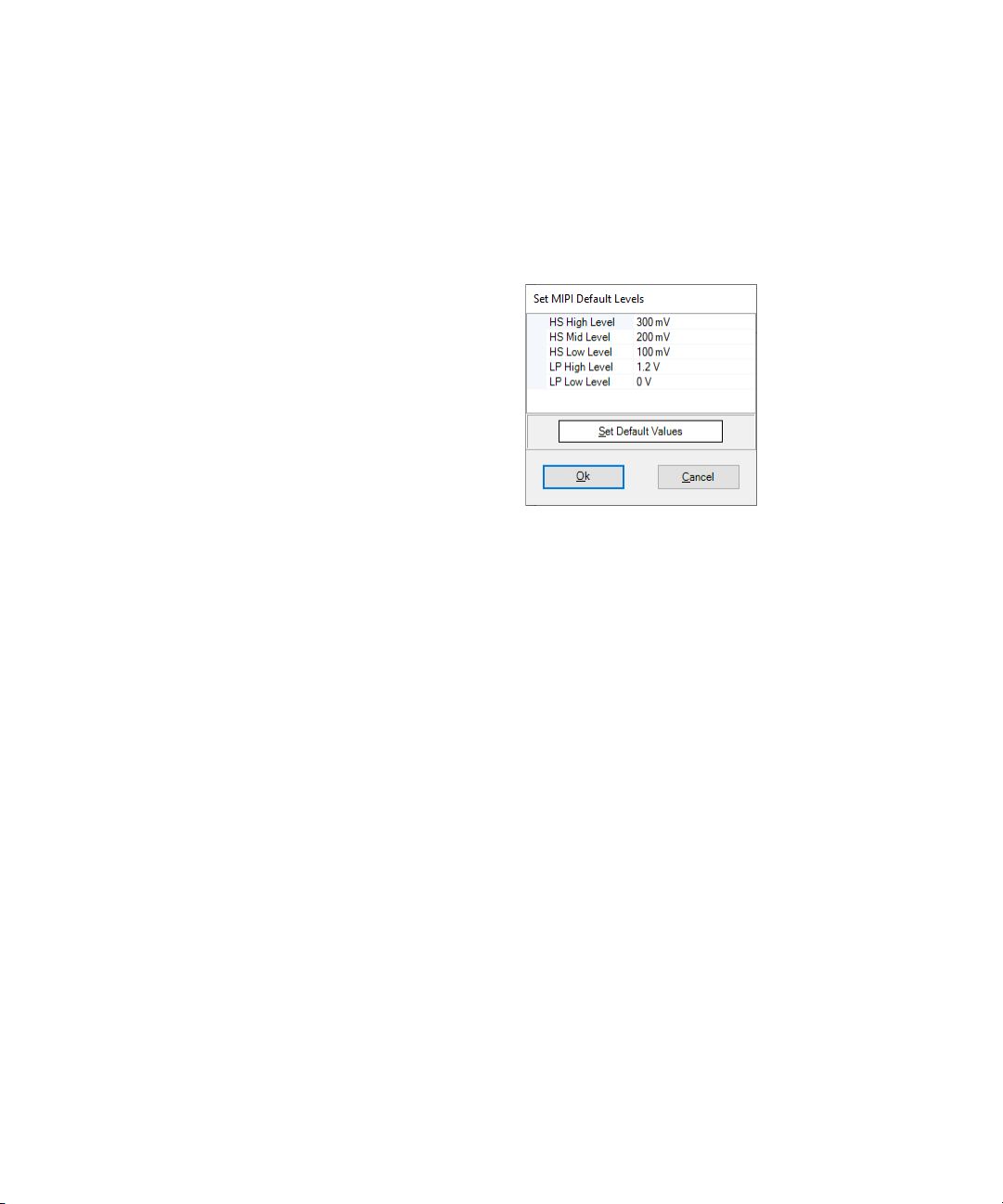
Editing Default Level Parameters
ValiFrame MIPI® C-PHY Station 2
On the Configure DUT panel, click the Edit Default Levels... button to edit
various MIPI
window is displayed in Figure 11.
Figure 11 Set MIPI Default Levels window
• HS High Level—Sets the High Speed Mode high voltage level.
• HS Mid Level—Sets the High Speed Mode mid voltage level.
• HS Low Level—Sets the High Speed Mode low voltage level.
• LP High Level—Sets the Low Power high voltage level.
• LP Low Level—Sets the Low Power low voltage level.
Click Set Default Values button to reset the level settings to the default
values.
®
C-PHY level parameters. The Set MIPI Default Levels
Click OK to return to the Configure DUT panel.
Keysight N5991MC2A MIPI® C-PHY Test Automation Software Platform User Guide 27
2 ValiFrame MIPI® C-PHY Station
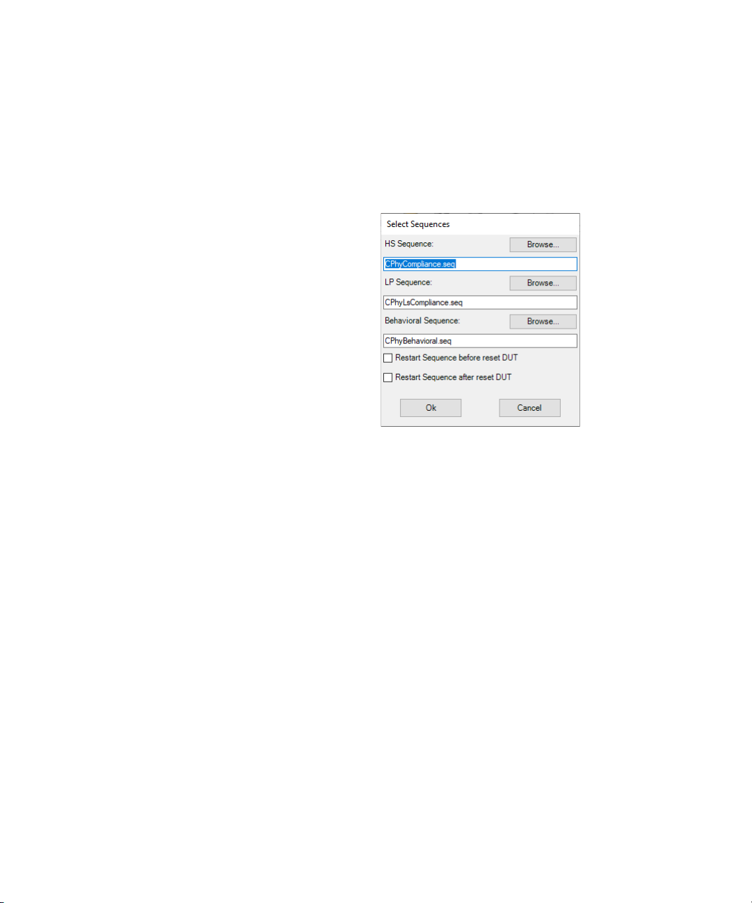
Selecting Sequences
On the Configure DUT panel, click the Select Sequences... button to edit
various MIPI
window is displayed in Figure 12.
Figure 12 Select Sequences window
• HS Sequence—The pattern used for high speed data signal tests. Click
the Browse… button to select the desired sequence.
• LP Sequence—The pattern used for low power signal tests. Click the
Browse… button to select the desired sequence.
• Behavioral Sequence—The pattern used for behavioral tests. Click the
Browse… button to select the desired sequence.
• Restart Sequence before reset DUT—Select this check box to restart the
sequences before the DUT transmission.
• Restart Sequence after reset DUT—Select this check box to restart the
sequences after the DUT transmission.
®
C-PHY sequence parameters. The Select Sequences
Click OK to return to the Configure DUT panel.
After configuring the parameters, click OK on the Configure DUT window.
28 Keysight N5991MC2A MIPI® C-PHY Test Automation Software Platform User Guide

Keysight N5991MC2A MIPI® C-PHY Test Automation
Software Platform
User Guide
3 Using the Software
Introduction / 30
Selecting, Modifying & Running Tests / 32
®
C-PHY Parameters / 36
MIPI
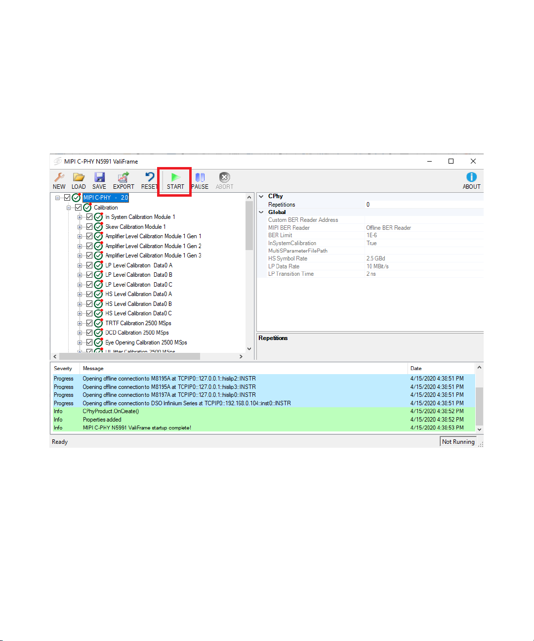
3 Using the Software
Introduction
All calibration and test procedures are included in the respective groups in
a manner similar to how they are organized in the specifications.
Figure 13 MIPI® C-PHY calibration and test window
The parameter grid on the right side of the window shows the parameters,
which are related to the selected procedures.
The log list at the bottom of the window shows calibration and test status
messages (regular progress updates as well as warnings and error
messages).
To start one or more procedures, select the corresponding check box. The
Start button is enabled and turns green in color. Click Start to run the
selected procedures.
30 Keysight N5991MC2A MIPI® C-PHY Test Automation Software Platform User Guide
 Loading...