

Page 1
Keysight
Combiner, and Mechanical Switches
Upgrade Kit
For Version 6, Single-Source Synthesizers
To Upgrade PNA-X N5244/5B Option 217 to N5244/5B Option 222 and
N5244/5B Option 219 to N5244/5B Option 224
For Analyzers with Serial Numbers Prefixed MY/SG/US5201 and Above
Upgrade Kit Order Number: N5244AU-932, N5245AU-932, N5244BU-224
and N5245BU-224 Keysight Kit Number: N5245-60111
Installation Note
Page 2

Notices
© Keysight Technologies, Inc.
2009-2021
No part of this manual may be
reproduced in any form or by any
means (including electronic storage
and retrieval or translation into a
foreign language) without prior
agreement and written consent from
Keysight Technologies, Inc. as
governed by United States and
international copyright laws.
Trademark Acknowledgments
Manual Part Number
N5245-90111
Edition
Edition 2, March 2021
Supersede March 2017
Printed in USA/Malaysia
Published by:
Keysight Technologies
1400 Fountaingrove Parkway
Santa Rosa, CA 95403
Warranty
THE MATERIAL CONTAINED IN THIS
DOCUMENT IS PROVIDED “AS IS,”
AND IS SUBJECT TO BEING
CHANGED, WITHOUT NOTICE, IN
FUTURE EDITIONS. FURTHER, TO
THE MAXIMUM EXTENT PERMITTED
BY APPLICABLE LAW, KEYSIGHT
DISCLAIMS ALL WARRANTIES,
EITHER EXPRESS OR IMPLIED WITH
REGARD TO THIS MANUAL AND
ANY INFORMATION CONTAINED
HEREIN, INCLUDING BUT NOT
LIMITED TO THE IMPLIED
WARRANTIES OF
MERCHANTABILITY AND FITNESS
FOR A PARTICULAR PURPOSE.
KEYSIGHT SHALL NOT BE LIABLE
FOR ERRORS OR FOR INCIDENTAL
OR CONSEQUENTIAL DAMAGES IN
CONNECTION WITH THE
FURNISHING, USE, OR
PERFORMANCE OF THIS
DOCUMENT OR ANY INFORMATION
CONTAINED HEREIN. SHOULD
KEYSIGHT AND THE USER HAVE A
SEPARATE WRITTEN AGREEMENT
WITH WARRANTY TERMS
COVERING THE MATERIAL IN THIS
DOCUMENT THAT CONFLICT WITH
THESE TERMS, THE WARRANTY
TERMS IN THE SEPARATE
AGREEMENT WILL CONTROL.
Technology Licenses
The hard ware and/or software
described in this document are
furnished under a license and may be
used or copied only in accordance
with the terms of such license.
U.S. Government Rights
The Software is “commercial
computer software,” as defined
by Federal Acquisition Regulation
(“FAR”) 2.101. Pursuant to FAR
12.212 and 27.405-3 and
Department of Defense FAR
Supplement (“DFARS”) 227.7202,
the U.S. government acquires
commercial computer software
under the same terms by which
the software is customarily
provided to the public.
Accordingly, Keysight provides
the Software to U.S. government
customers under its standard
commercial license, which is
embodied in its End User License
Agreement (EULA), a copy of
which can be found at
http://www.keysight.com/find/sweula
The license set forth in the EULA
represents the exclusive authority
by which the U.S. government
may use, modify, distribute, or
disclose the Software. The EULA
and the license set forth therein,
does not require or permit,
among other things, that
Keysight: (1) Furnish technical
information related to
commercial computer software
or commercial computer
software documentation that is
not customarily provided to the
public; or (2) Relinquish to, or
otherwise provide, the
government rights in excess of
these rights customarily provided
to the public to use, modify,
reproduce, release, perform,
display, or disclose commercial
computer software or
commercial computer software
documentation. No additional
government requirements
beyond those set forth in the
EULA shall apply, except to the
extent that those terms, rights, or
licenses are explicitly required
from all providers of commercial
computer software pursuant to
the FAR and the DFARS and are
set forth specifically in writing
elsewhere in the EULA. Keysight
shall be under no obligation to
update, revise or otherwise
modify the Software. With
respect to any technical data as
defined by FAR 2.101, pursuant
to FAR 12.211 and 27.404.2 and
DFARS 227.7102, the U.S.
government acquires no greater
than Limited Rights as defined in
FAR 27.401 or DFAR 227.7103-5
(c), as applicable in any technical
data.
Safety Notices
A CAUTION notice denotes a hazard. It
calls attention to an operating
procedure, practice, or the like that,
if not correctly performed or adhered
to, could result in damage to the
product or loss of important data. Do
not proceed beyond a CAUTION
notice until the indicated conditions
are fully understood and met.
A WARNING notice denotes a hazard.
It calls attention to an operating
procedure, practice, or the like that,
if not correctly performed or adhered
to, could result in personal injury or
death. Do not proceed beyond a
WARNING notice until the indicated
conditions are fully understood and
met.
Page 3
Keysight Second Source, Combiner, and Mechanical Switches Upgrade Kit
Upgrade Kit Number: N5245-60111
Installation Note
Description of the Upgrade
If you had an A model PNA-X with Option 219/419 with Option H85 that
was upgraded to a B model, please refer to Options 217/417. If you had an
A model PNA-X with Option 224/423 with Option H85 that was upgraded
to a B model then refer to Option 222/422.
Some of the assembly drawings in this document may be different from
your instrument, but the process is similar for both an "A" model and "B"
model instruments.
This upgrade converts your standard 2-port configurable test set analyzer
(N5244A/B Option 217 or N5245A/B Option 217) to an N5244/5A Option
222 or N5244/5B Option 222 and (N5244A/B Option 219 or N5245A/B
Option 219) to an N5244A/B Option 224 or N5245A/B Option 224 by adding:
— a second source assembly
— a second 13.5 GHz synthesizer board
—two additional doublers
— source outputs routed to the front panel
— source outputs routed to the rear panel
— a mechanical switch to each source port channel
— a source combiner to the port 1 channel
— rear-panel test set inputs
3
Page 4

-
Description of the Upgrade
Getting Assistance from Keysight
Getting Assistance from Keysight
Installing this upgrade kit requires special skills and experience. If you think
you may not be qualified to do the work, or need advice, contact Keysight.
Contacting Keysight
Assistance with test and measurements needs and information on finding a
local Keysight office are available on the Web at:
http://www.keysight.com/find/assist
If you do not have access to the Internet, please contact your Keysight field
engineer.
In any correspondence or telephone conversation, refer to the Keysight
product by its model number and full serial number. With this information,
the Keysight representative can determine whether your product is still
within its warranty period.
If You Have Problems With the Upgrade Kit Contents
Keysight stands behind the quality of the upgrade kit contents. If you have
problems with any item in the kit, refer to www.keysight.com and the Contact
Keysight link.
4 Installation Note N5245-90111
Page 5

Description of the Upgrade
Getting Prepared
Getting Prepared
The PNA contains extremely sensitive components that can be ruined if
mishandled. Follow instructions carefully when making cable connections,
especially wire harness connections.
The person performing the work accepts responsibility for the full cost of
the repair or replacement of damaged components.
To successfully install this upgrade kit, you will need the following:
—A license key - refer to “License Key Redemption” below.
— A PDF copy or a paper copy of the PNA Service Guide - refer to
— An ESD-safe work area - refer to “Protecting Your Workspace from
— Correct tools - refer to “Tools Required for the Installation” on page 8.
“Downloading the Online PNA Service Guide” below.
Electrostatic Discharge” below.
— Enough time - refer to “About Installing the Upgrade” on page 8.
— Test equipment for the post-upgrade adjustments and full instrument
calibration. To view the equipment list, click the Chapter 3 bookmark “Tests
and Adjustments” in the PDF Service Guide
1
.
1. See “Downloading the Online PNA Service Guide” on page 7.
Installation Note N5245-90111 5
Page 6

-
Description of the Upgrade
Getting Prepared
License Key Redemption
The only difference between an A model license key redemption and a B
model is that the A model uses a 12-character license key and the B model
uses a license key file.
Ensure that you are connected to an external server, before attempting to
download your email and license key file.
If you are unfamiliar with the licensing process, refer to the
http://literature.cdn.keysight.com/litweb/pd f/N5242-90006.pdf
(A models) or
http://literature.cdn.keysight.com/litweb/pd f/N5242-90024.pdf
(B models).
The enclosed Software Entitlement Certificate is a receipt, verifying that
you have purchased a licensed option for the PNA of your choice. You must
now use a Keysight Web page to request a license key for the instrument
that will receive the option.
To enable the option product, you must request license key(s) from the
Keysight Software Manager:
http://www.keysight.com/find/softwaremanager.
To complete the request, you will need to gather the following information:
— From the certificate
— Order number
— Certificate number
— From your instrument
(Instrument information is available in the network analyzer - on the
toolbar, click Help, then click About Network Analyzer.)
— Model number
— Serial number
— Host ID (For B models the host ID is the model and serial numbers.)
Using the information just gathered, you must request license key(s) from the
Keysight Software Manager:
http://www.keysight.com/find/softwaremanager.
You will need to provide an email address, to which Keysight will promptly
email your license key file. Refer to “License Key Redemption” on page 6.
6 Installation Note N5245-90111
Page 7

Description of the Upgrade
Getting Prepared
Downloading the Online PNA Service Guide
To view the online Service Guide for your PNA model number, use the following
steps:
1. Go to www.keysight.com.
2. In the Search box, enter the model number of the analyzer (Ex: N5242A)
and click Search.
3. Click Technical Support > Manuals.
4. Click Service Manual.
5. Click the service guide title to download the PDF file.
6. When the PDF of the Service Guide is displayed, scroll through the
Contents section bookmarks to locate the information needed.
Protecting Your Workspace from Electrostatic Discharge
For information, click on the Chapter 1 bookmark, “Electrostatic Discharge
1
Protection” in the PDF Service Guide
.
ESD Equipment Required for the Installation
Description Keysight Part Number
ESD grounding wrist strap 9300-1367
5-ft grounding cord for wrist strap 9300-0980
2 x 4 ft conductive table mat and 15-ft grounding wire 9300-0797
ESD heel strap (for use with conductive floors) 9300-1308
Installation Note N5245-90111 7
Page 8

-
Description of the Upgrade
Getting Prepared
Tools Required for the Installation
Description Qty Part Number
T-6 TORX driver - set to 4 in-lbs (0.45 N.m) 1 N/A
T-8 TORX driver - set to 6 in-lbs (0.68 N.m) 1 N/A
T-10 TORX driver - set to 9 in-lbs (1.02 N.m) 1 N/A
T-20 TORX driver - set to 21 in-lbs (2.38 N.m) 1 N/A
5/16-in (8 mm) nutsetter or open end torque wrench- set to 10 in-lbs
(1.13 N.m)
5/16-in (8 mm) nutsetter or open end torque wrench - set to 21 in-lbs
(2.38 N.m)
3/16-in (5 mm) nutsetter or open end torque wrench - set to 6 in-lbs
(0.68 N.m)
9/16-in (15 mm) nutsetter or open end torque wrench - set to 21 in-lbs
(2.38 N.m)
5/8-in (16 mm) nutsetter or open end torque wrench - set to 21 in-lbs
(2.38 N.m)
9 mm nutsetter or open end torque wrench - set to 21 in-lbs (2.38 N.m) 1 N/A
1/4-in (6 mm) open end wrench 1 N/A
1N/A
1N/A
1N/A
1N/A
1N/A
Use a 5/16-in torque wrench set to 10 in-lbs on all cable connections
except the front and rear panel cable connectors. On these, use a 9 mm
nutsetter or open end torque wrench set to 21 in-lb.
About Installing the Upgrade
Products affected N5244A/B Option 217/219 and N5245A/B Option 217/219
Installation to be performed by Keysight service center or personnel qualified by Keysight
Estimated installation time 5 hours
Estimated adjustment time 0.5 hours
Estimated full instrument calibration time 4.5 hours
8 Installation Note N5245-90111
Page 9

Description of the Upgrade
Items Included in the Upgrade Kit
Items Included in the Upgrade Kit
Check the contents of your kit against the following list. If any part is missing or
damaged, contact Keysight Technologies. Refer to “Getting Assistance from
Keysight” on page 4.
Table 1 Contents of Upgrade Kit N5245-60111
Ref
Desig.
- Installation note (this document) 1 N5245-90111
- Software Entitlement Certificate 1 5964-5145
A10 26.5 GHz source (2) assembly 1 5087-7780
A12 Doubler assembly, port 3 2 5087-7349
A13 Doubler assembly, port 4
A17 13.5 GHz source 2 synthesizer board 1 N5240-60074
A50 Port 1 mechanical switch
A53 Port 3 mechanical switch
A54 Combiner 1 11667-60021
- Bracket for combiner 1 N5245-00020
- Bracket for mechanical switches 3 N5245-00014
-Bracket for cables 1 N5245-00022
Description Qty Part Number
3 N1811-60031A51 SRC2 OUT1 mechanical switch
- Machine screw, M3.0 x 8, pan head (to attach cable bracket to deck) 2 0515-0372
- Machine screw, M2.0 x 20, pan head (to attach mechanical switches to brackets) 6 0515-1992
- Machine screw, M2 x 14, pan head (to attach combiner to bracket) 2 0515-0661
Machine screw, M3 x 6, pan head (6 to attach switch assemblies to deck; 2 to attach
combiner bracket to deck)
Machine screw, M4.0 x 10, pan head (2 to attach source 2 assy to chassis; 2 to attach
A12 doubler 3 to chassis; 2 to attach A13 doubler 4 to chassis)
- Machine screw, M3.0 x 18, pan head (to attach source bracket N5247-20136) 1 0515-0666
Machine screw, W/PATCH-LK 90-DEG, M3.0 x 20, pan head (to attach source
bracket N5247-20136)
- SMA Male straight, termination 50 ohm 2 1250-4261
- Cable clamp 5 1400-1334
- Bulkhead connectors 2 5063-1700
Installation Note N5245-90111 9
12 0515-0430
6 0515-0380
2 0515-2078
Page 10

-
Description of the Upgrade
Items Included in the Upgrade Kit
Table 1 Contents of Upgrade Kit N5245-60111
Ref
Desig.
Description Qty Part Number
- Washers for bulkhead connectors 2 2190-0016
- Nuts for bulkhead connectors 2 08360-20133
- Cap-protective, 1/4 –36 threads 1 5188-5406
- Front panel overlay – "A" models (Option 224) 1 N5245-80005
- Front panel overlay – "B" models (Option 224) 1 N5245-80027
- Front panel overlay – "B" models (Option 222) 1 N5245-80028
- Dust cap for test port 2 1401-0214
- Dust cap for test port 2 1401-0225
- Termination, 2.4 mm 50 GHz load 1 0955-2394
W2 A10 source (2) P1 to A17 13.5 GHz source (2) synthesizer J1207 1 N5245-20100
W7 A10 source (2) P5 to A12 port 3 doubler 1 N5245-20034
W8 A10 source (2) P3 to A13 port 4 doubler 1 N5245-20035
W9 A10 source (2) P4 to A12 port 3 doubler 1 N5245-20032
W10 A12 port 3 doubler to A13 port 4 doubler 1 N5245-20033
W13 A12 port 3 doubler to W14 1 N5245-20036
W15 A13 port 4 doubler to W16 1 N5245-20036
W16 Front panel SRC 2 OUT 2 to W15 1 N5245-20053
W77 A14 frequency ref (J7) to A17 13.5 GHz (source 2) synth (J5) 1 N5242-60030
W105 A50 port 1 mechanical switch to W11 1 N5245-20064
W106 A50 port 1 mechanical switch to A29 port 1 reference coupler 1 N5245-20065
W107 A50 port 1 mechanical switch to PORT 1 SW SRC OUT (J11) 1 N5245-20068
W108 Rear-panel PORT 1 COMB THRU IN (J10) to A54 combiner 1 N5245-20094
W109 Rear-panel PORT 1 COMB ARM IN (J9) to A54 combiner 1 N5245-20093
W110 A50 port 1 mechanical switch to A54 combiner 1 N5245-20067
W111 A51 SRC2 OUT1 mechanical switch mechanical switch to W13 1 N5245-20058
W112 Front panel SRC 2 OUT 1 to
A51
SRC2 OUT1 mechanical switch 1 N5245-20078
W113 A51 SRC2 OUT1 mechanical switch to PORT 3 SW SRC OUT (J8) 1 N5245-20069
W114
Rear-panel PORT 3 SW TSET IN (J7) to A51
SRC2 OUT1
mechanical switch
1 N5245-20070
W119 A53 port 2 mechanical switch to W17 1 N5245-20063
10 Installation Note N5245-90111
Page 11
Description of the Upgrade
Installation Procedure for the Upgrade
Table 1 Contents of Upgrade Kit N5245-60111
Ref
Desig.
W120 A53 port 2 mechanical switch to A32 port 2 reference coupler 1 N5245-20062
W121 A53 port 2 mechanical switch to PORT 2 SW SRC OUT (J2
W122 A53 port 2 mechanical switch to PORT 2 TSET IN (J1
W123 Rear panel jumper 3 N5245-20155
- Bracket, source 1 N5247-20136
Description Qty Part Number
)
)
1 N5245-20071
1 N5245-20072
Extra quantities of items such as protective plastic caps, screws, cable ties,
and cable clamps may be included in this upgrade kit. It is normal for some
of these items to remain unused after the upgrade is completed.
Installation Procedure for the Upgrade
The network analyzer must be in proper working condition prior to installing
this option. Any necessary repairs must be made before proceeding with this
installation.
This installation requires the removal of the analyzer’s protective
outer covers. The analyzer must be powered down and
disconnected from the mains supply before performing this
procedure.
Overview of the Installation Procedure
“Step 1. Obtain a Keyword and Verify the Information.”
“Step 2. Remove the Outer Cover.”
“Step 3. Remove the Inner Cover.”
“Step 4. Remove the Front Panel Assembly.”
“Step 5. Remove the A23 Test Set Motherboard.”
“Step 6. Remove the A24 IF Multiplexer Motherboard.”
“Step 7. Remove the Some Existing Cables.”
“Step 8. Assemble the A50, A51, and A53 Mechanical Switch Assemblies.”
“Step 9. Install the Mechanical Switch Assemblies.”
“Step 10. Assemble and Install the A54 Combiner Assembly.”
“Step 11. Install the Source 2 Front Panel Connectors.”
Installation Note N5245-90111 11
Page 12

-
Description of the Upgrade
Installation Procedure for the Upgrade
“Step 12. Install Bracket to A10 26.5 GHz Source 2 Assembly.”
“Step 13. Assemble the A10 26.5 GHz Source 2 Assembly.”
“Step 14. Assemble and Install the A12 and A13 Doubler Assemblies.”
“Step 15. Install the A10 26.5 GHz Source 2 Assembly and Cables.”
“Step 16. Install the A17 13.5 GHz (Source 2) Synthesizer Board and Cables.”
“Step 17. Install the New Cables.”
“Step 18. Install Rear Panel Hardware.”
“Step 19. Reinstall the A24 IF Multiplexer Board.”
“Step 20. Reinstall the A23 Test Set Motherboard.”
“Step 21. Remove the Old Lower Front Panel Overlay.”
“Step 22.Reinstall Front Panel Assembly.”
“Step 23. Install the New Lower Front Panel Overlay.”
“Step 24. Reinstall the Inner Cover.”
“Step 25. Reinstall the Outer Cover.”
“Step 26. Remove Option 217 or 219 Licenses (B Models Only).”
“Step 27. Enable Option 224.”
“Step 28. Perform Post-Upgrade Adjustments and Calibration.”
“Step 29. Prepare the PNA for the User.”
Step 1.Obtain a Keyword and Verify the Information
Follow the instructions on the Software Entitlement Certificate supplied to
obtain a license key for installation of this upgrade. Refer to “License Key
Redemption” on page 6.
Verify that the model number, serial number, and option number information
on the license key match those of the instrument on which this upgrade will be
installed.
If the model number, serial number, or option number do not match those on
your license key, you will not be able to install the option. If this is the case,
contact Keysight for assistance before beginning the installation of this
upgrade. Refer to “Contacting Keysight” on page 4.
12 Installation Note N5245-90111
Page 13

Description of the Upgrade
Installation Procedure for the Upgrade
Once the license key (A models) or license key file (B models) has been
received and the information verified, you can proceed with the installation at
“Step 2. Remove the Outer Cover” on page 13.
If the model number, serial number, or option number do not match those
on your license key (A models) or license key file (B models), you will not
be able to install the option. If this is the case, contact Keysight for
assistance before beginning the installation of this upgrade. Refer to
“Contacting Keysight” on page 4.
Step 2. Remove the Outer Cover
For instructions, click the Chapter 7 bookmark “Removing the Covers” in the
1
PDF Service Guide
.
Step 3.Remove the Inner Cover
For instructions, click the Chapter 7 bookmark “Removing the Covers” in the
1
PDF Service Guide
.
Step 4.Remove the Front Panel Assembly
For instructions, click the Chapter 7 bookmark “Removing and Replacing the
1
Front Panel Assembly” in the PDF Service Guide
.
Step 5.Remove the A23 Test Set Motherboard
For instructions, click the Chapter 7 bookmark “Removing and Replacing the
1
A23 Test Set Motherboard” in the PDF Service Guide
.
Step 6. Remove the A24 IF Multiplexer Motherboard
For instructions, click the Chapter 7 bookmark “Removing and Replacing the
A24 IF Multiplexer Board” in the PDF Service Guide
1
.
Step 7. Remove the Some Existing Cables
Be careful not to damage the center pins of the semirigid cables. Some
flexing of the cables may be necessary but do not over-bend them.
1. Place the analyzer bottom-side up on a flat surface.
1. See “Downloading the Online PNA Service Guide” on page 7.
Installation Note N5245-90111 13
Page 14
-
Description of the Upgrade
Installation Procedure for the Upgrade
2. Remove the following cables in the order listed. To see an image showing
the location of these cables, click the Chapter 6 bookmark “Bottom RF
Cables, Standard 2-Port Configuration, Option 219” in the PDF Service
1
Guide
.
These cables may be discarded - they will not be reinstalled (Option 217/219).
— W18 (N5245-20049) A32 test port 2 receiver coupler to W17
— W12 (N5245-20050) A29 test port 1 receiver coupler to W11
These cables must be saved - they will reinstalled (Option 217/222 Only).
— W18 (N5245-20106) A32 test port 2 reference coupler to W17
— W12 (N5245-20045) A29 test port 1 reference coupler to W11
These four cables must be saved - they will be reinstalled All Options).
— W98 (N5245-20056) A46 port 1 receiver attenuator to A27 mixer brick
(A)
— W43 (N5245-20009) A37 reference mixer switch to A27 mixer brick (R1)
— W47 (N5245-20119) Front panel REF 2 RCVR R2 IN to A27 mixer brick (R2)
— W104 (N5245-20057) A49 port 2 receiver attenuator to A27 mixer brick (B)
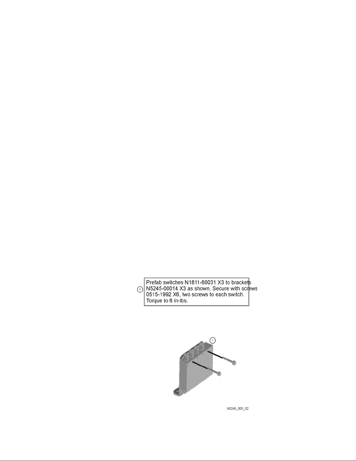
Step 8. Assemble the A50, A51, and A53 Mechanical Switch
Assemblies
Refer to Figure 1 for this step of the procedure. New parts are listed in Table 1
on page 9.
Figure 1 Mechanical Switch Assembly
14 Installation Note N5245-90111
Page 15

Description of the Upgrade
Installation Procedure for the Upgrade
Step 9. Install the Mechanical Switch Assemblies
Install the A50, A51, and A53 mechanical switches. For instructions, click the
Chapter 7 bookmark, “Removing and Replacing the A50-A53 Mechanical
Switches and the A54 Combiner” in the PDF Service Guide
listed in Table 1 on page 9 of this document.
1
. New parts are
1. See “Downloading the Online PNA Service Guide” on page 7.
Installation Note N5245-90111 15
Page 16
-
Description of the Upgrade
Installation Procedure for the Upgrade
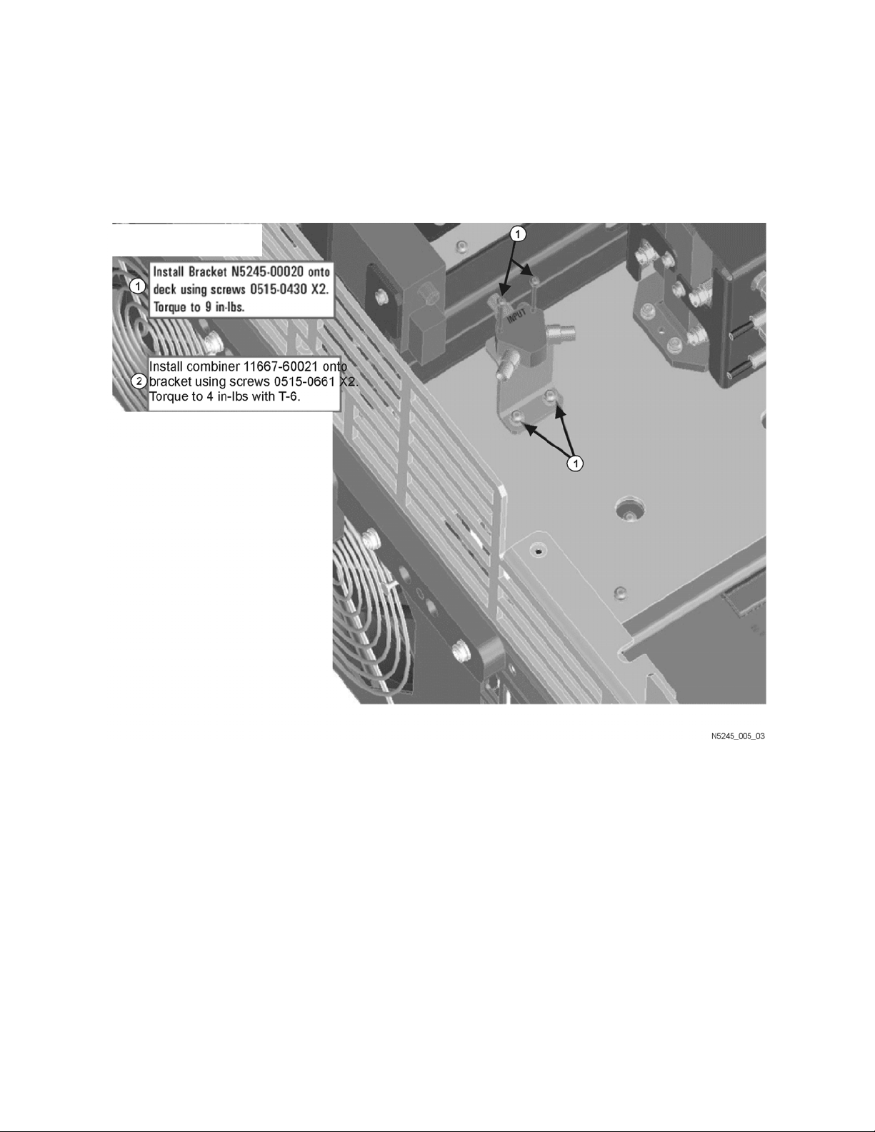
Step 10. Assemble and Install the A54 Combiner Assembly
Refer to Figure 2 for this step of the procedure. New parts are listed in Table 1
on page 9.
Figure 2 A54 Combiner Assembly and Installation (N5245-00020)
16 Installation Note N5245-90111
Page 17
Description of the Upgrade
Installation Procedure for the Upgrade
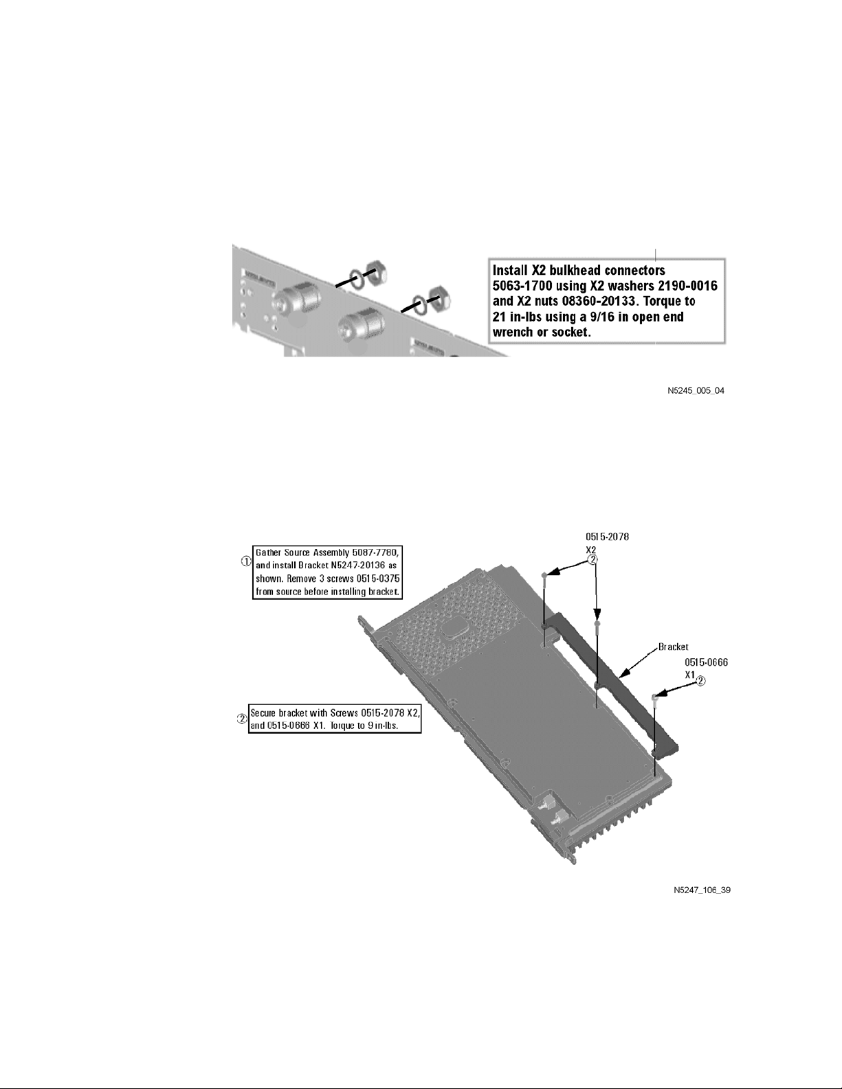
Step 11. Install the Source 2 Front Panel Connectors
Refer to Figure 3 for this step of the procedure. New parts are listed in Table 1
on page 9.
Figure 3 Source 2 Front Panel Connectors Installation
Step 12. Install Bracket to A10 26.5 GHz Source 2 Assembly
Follow the two instructions shown in Figure 4.
Figure 4 A10 Source 2 Assembly Bracket Installation (N5247-20136)
Installation Note N5245-90111 17
Page 18
-
Description of the Upgrade
Installation Procedure for the Upgrade
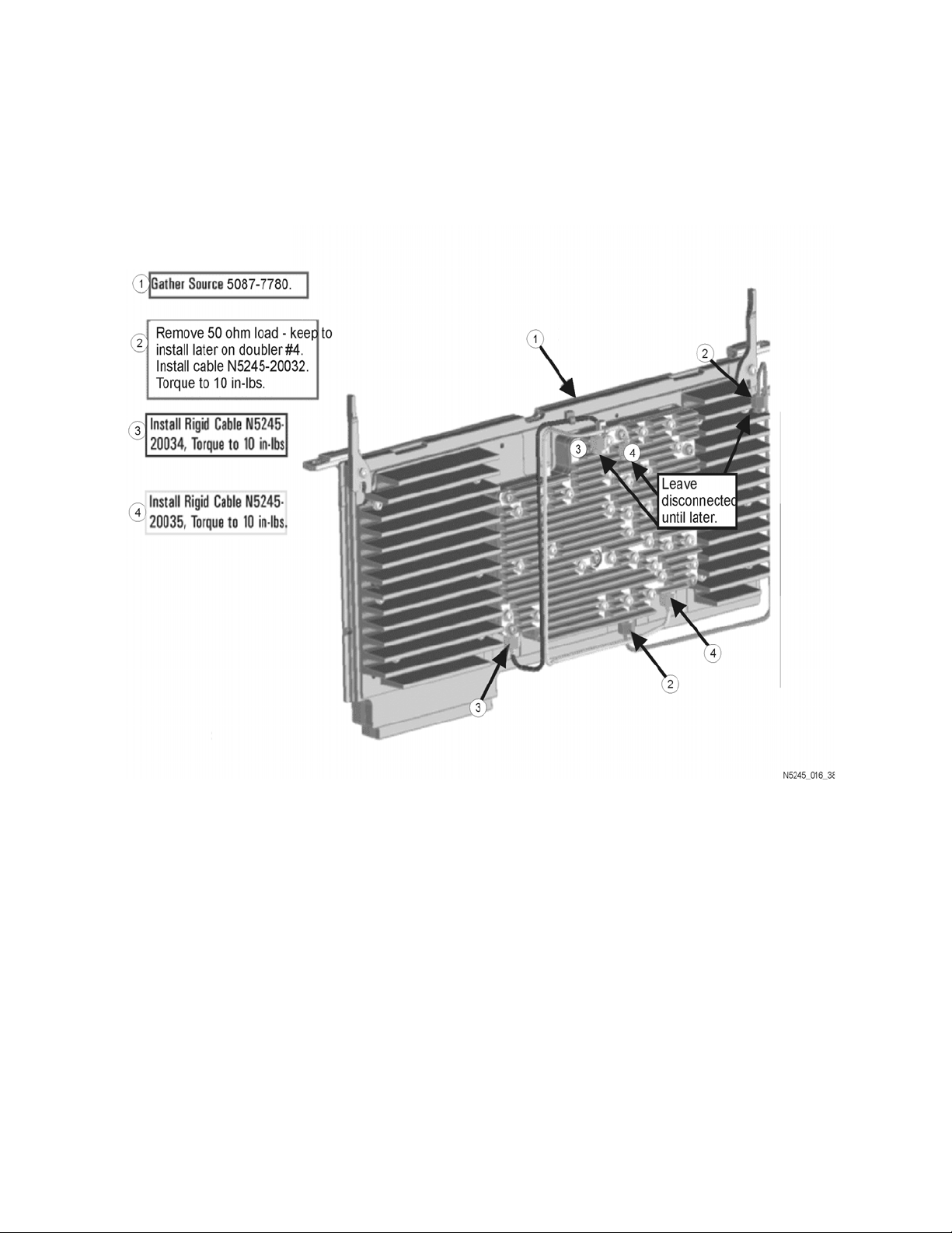
Step 13. Assemble the A10 26.5 GHz Source 2 Assembly
Follow the four instructions shown in Figure 5.
Figure 5 A10 Source 2 Assembly (N5245-20032, N5245-20034, & N5245-20035)
18 Installation Note N5245-90111
Page 19
Description of the Upgrade
Installation Procedure for the Upgrade
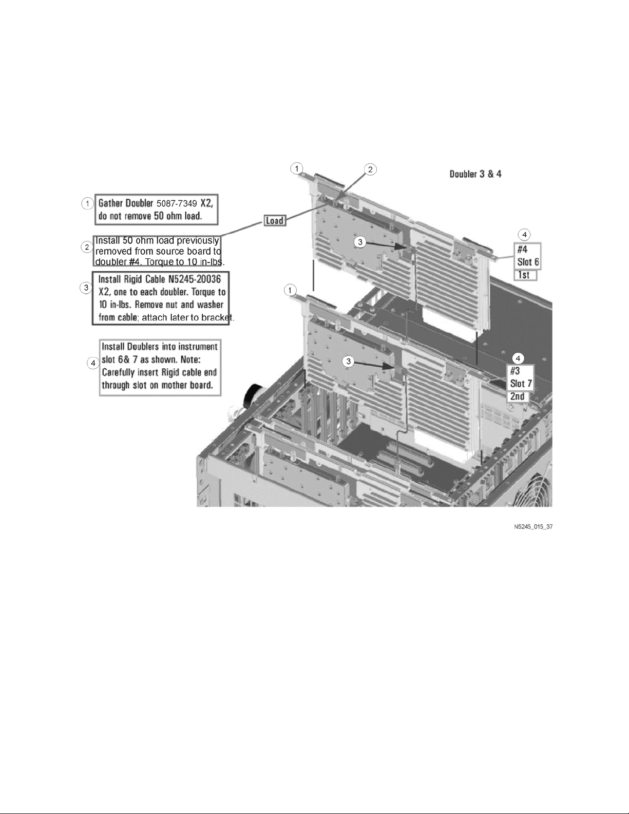
Step 14. Assemble and Install the A12 and A13 Doubler Assemblies
Follow the four instructions show in Figure 6.
Figure 6 A12 and A13 Doubler Assemblies Installation (N5245-20036)
Installation Note N5245-90111 19
Page 20
-
Description of the Upgrade
Installation Procedure for the Upgrade
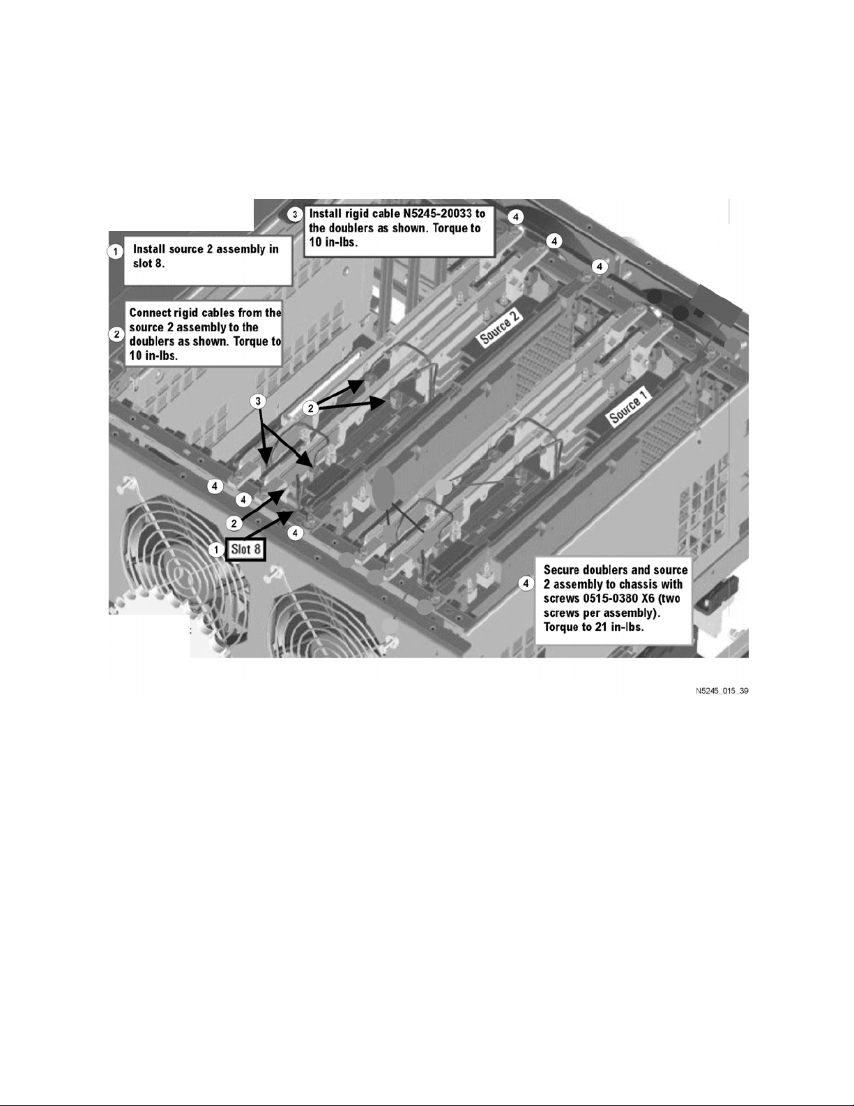
Step 15. Install the A10 26.5 GHz Source 2 Assembly and Cables
Follow the four instructions shown in Figure 7.
Figure 7 A10 Source 2 Assembly Installation (N5245-20033)
20 Installation Note N5245-90111
Page 21

Description of the Upgrade
Installation Procedure for the Upgrade
Step 16. Install the A17 13.5 GHz (Source 2) Synthesizer Board and
Cables
1. Install gray cable W77 (N5242-60030) to connector J5 of the A17 (source
2) synthesizer board (N5240-60074). The loose end of the cable will be
connected on the A14 frequency reference board (J7) after the A17 board
has been installed in the analyzer.
2. Install the A17 board into slot 2 in the motherboard. To see an image
showing the location of the A17 board in the motherboard, click the
Chapter 6 bookmark “Top Assemblies, All Options” in the PDF Service
1
Guide
3. Connect cable W2 (N5245-20100) between the A10 source 2 board and
the A17 (source 2) synthesizer board, positioning the cable in the wire
looms. Tighten the cable connectors to 10 in-lbs using a 5/16-in torque
wrench.
4. Connect the loose end of new gray flex cable W77 (N5242-60030) on the
A14 frequency reference board (J7). (The other end of this cable was
previously connected to J5 of the source 2 synthesizer board.)
.
1. See “Downloading the Online PNA Service Guide” on page 7.
Installation Note N5245-90111 21
Page 22
-
Description of the Upgrade
Installation Procedure for the Upgrade
Step 17. Install the New Cables
Follow instructions carefully when making cable connections, especially
wire harness connections. Incorrect connections can destroy components,
resulting in additional customer costs.
To see an image showing the location of these cables, click the Chapter 6
bookmarks “Bottom RF Cables, 2-Port Configuration, Option 224” in the PDF
1
Service Guide
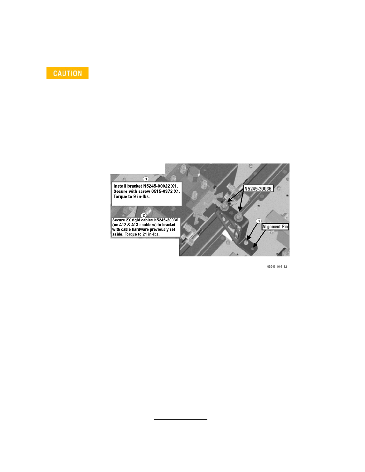
Install the following new cables in the order listed.
Follow the two instructions shown in Figure 8 in this document.
Figure 8 Semigrid Cables Installation (N5245-20036 x2)
. New parts are listed in Table 1 on page 9.
— W13 (N5245-20036) A12 port 3 doubler to W14 (connected to the doubler
in an earlier step)
— W15 (N5245-20036) A13 port 4 doubler to W16 (connected to the doubler
in an earlier step)
— W122 (N5245-20072) A53 port 2 mechanical switch to PORT 2 TSET IN (J1)
— W121 (N5245-20071) A53 port 2 mechanical switch to PORT 2 SW SRC
OUT (J2)
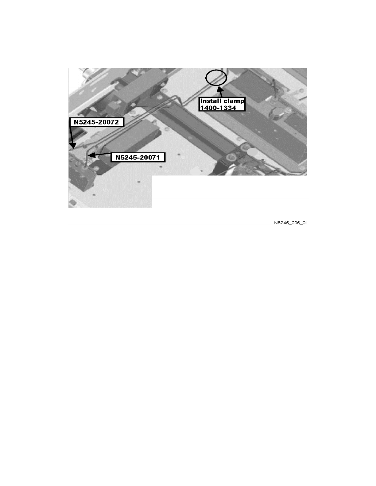
* As shown in Figure 9, install a clamp (part number 1400-1334) to secure
W121 (N5245-20071) and W122 (N5245-20072).
1. See “Downloading the Online PNA Service Guide” on page 7.
22 Installation Note N5245-90111
Page 23
Description of the Upgrade
Installation Procedure for the Upgrade
Figure 9 Location of Cable Clamp to Secure W121 (N5245-20071) and W122
(N5245-20072)
— W114 (N5245-20070) Rear-panel PORT 3 SW TSET IN (J7) to A51 SRC2
OUT1 mechanical switch
— W113 (N5245-20069) A51 SRC2 OUT1 mechanical switch to PORT 3 SW
SRC OUT (J8)
— W109 (N5245-20093) Rear-panel PORT 1 COMB ARM IN (J9) to A54
combiner
— W108 (N5245-20094) Rear-panel PORT 1 COMB THRU IN (J10) to A54
combiner
— W107 (N5245-20068) A50 port 1 mechanical switch to PORT 1 SW SRC
OUT (J11)
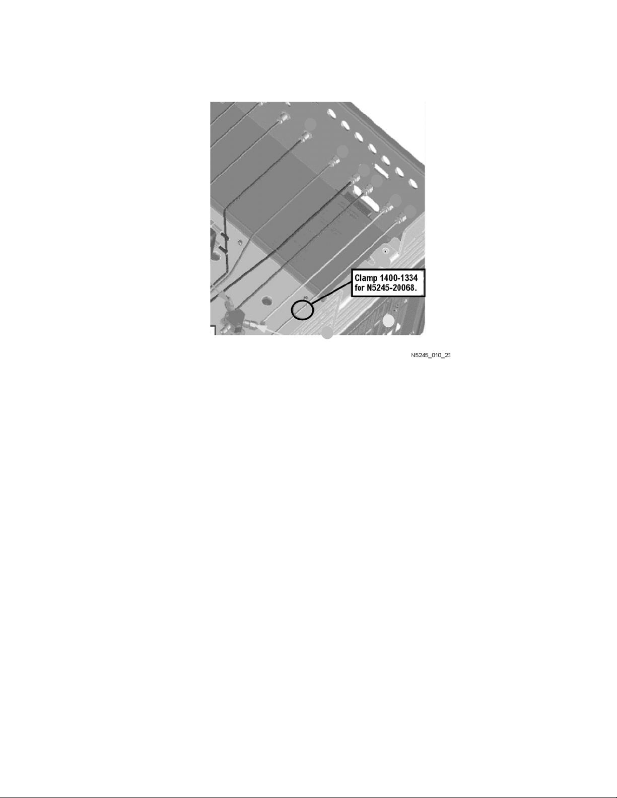
* As shown in Figure 9-1, install clamp part number 1400-1334 to secure
W107 (N5245-20068).
Installation Note N5245-90111 23
Page 24
-
Description of the Upgrade
Installation Procedure for the Upgrade
Figure 9-1 Location of Cable Clamp to Secure W107 (N5245-20068)
— W120 (N5245-20062) A53 port 2 mechanical switch to A32 port 2
reference coupler
— W119 (N5245-20063) A53 port 2 mechanical switch to W17
— W106 (N5245-20065) A50 port 1 mechanical switch to A29 port 1
reference coupler
— W105 (N5245-20064) A50 port 1 mechanical switch to A29 port 1
reference coupler
— W111 (N5245-20058) A51 SRC2 OUT1 mechanical switch
mechanical switch to W13
— W47 (reuse) (N5245-20119) Front panel REF 2 RCVR R2 IN to A27
mixer brick (R2)
— W43 (reuse) (N5245-20009) A37 reference mixer switch to A27 mixer
brick (R1)
— W110 (N5245-20067) A50 port 1 mechanical switch to A54 combiner
— W98 (reuse) (N5245-20056) A46 port 1 receiver attenuator to A27
mixer brick (A)
— W104 (reuse) (N5245-20057) A49 port 2 receiver attenuator to A27
mixer brick (B)
— W16 (N5245-20053) Front panel SRC 2 OUT 2 to W15
24 Installation Note N5245-90111
Page 25

Description of the Upgrade
Installation Procedure for the Upgrade
— W112 (N5245-20078) Front panel SRC 2 OUT 1 to A51 SRC2 OUT1
mechanical switch
Step 18. Install Rear Panel Hardware
To see an image of the rear panel assembly, click the Chapter 6 bookmark
“Rear Panel Assembly, All Options” in the PDF Service Guide1.
1. Secure seven hex nuts on the rear panel bulkhead connectors to 21 in-lbs
using a 9mm nut bit.
2. Go back and re-torque the seven hex nuts to 21 in-lbs using a manual
torque wrench.
3. Install the 2.4 mm 50 GHz termination (0955-2394) on J7, port 3.
4. Install three rear panel jumpers (N5245-20155) between the following
connector pairs:
— SW TSET IN (J1) and SW SRC OUT (J2)
— COMB ARM IN (J10) and SW SRC OUT (J11)
— COMB ARM IN (J9) and SW SRC OUT (J8)
Two hole plugs (6960-0523) remain in the rear panel.
Step 19.Reinstall the A24 IF Multiplexer Board
For instructions, click the Chapter 7 bookmark “Removing and Replacing the
A24 IF Multiplexer Board” in the PDF Service Guide1.
Installation Note N5245-90111 25
Page 26

-
Description of the Upgrade
Installation Procedure for the Upgrade
Step 20.Reinstall the A23 Test Set Motherboard
For instructions on reinstalling the board, click the Chapter 7 bookmark
“Removing and Replacing the A23 test set motherboard” in the PDF Service
1
Guide
If not already done in a previous step, install the following new wire harnesses
in the order listed. To see an image showing their location, click the Chapter 6
bookmark “Bottom Ribbon Cables and Wire Harnesses, 4-Port, Option 423” in
the PDF Service Guide
1. Wire harness (part of mechanical switch assembly), A23 test set
2. Wire harness (part of mechanical switch assembly), A23 test set
3. Wire harness (part of mechanical switch assembly), A23 test set
.
1
. New parts are listed in Table 1 on page 9.
motherboard J101 to A50 port 1 mechanical switch
motherboard J104 to A51 SRC2 OUT1 mechanical switch
motherboard J102 to A53 port 2 mechanical switch
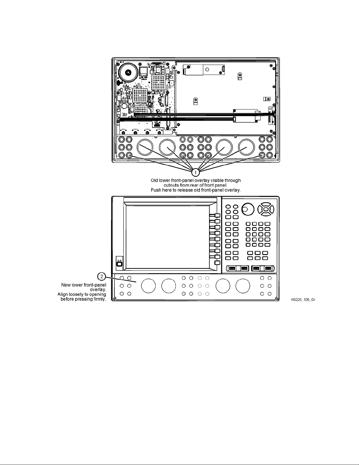
Step 21. Remove the Old Lower Front Panel Overlay
Refer to Figure 10 for this step of the procedure. New parts are listed in Table 1
on page 9.
1. From the back side of the front panel, use a blunt object in the cutouts in
the lower front dress panel to push on the old overlay (item
separate it from the front dress panel.
2. From the front side of the front panel, pull off the overlay completely and
discard it.
3. Remove any adhesive remaining on the front panel.
IMPORTANT! To avoid possible damage to the lower front panel overlay,
do not attempt to attach the lower front panel label until “Step 15. Install
the A10 26.5 GHz Source 2 Assembly and Cables” on page 20.
①
) and
1. See “Downloading the Online PNA Service Guide” on page 7.
26 Installation Note N5245-90111
Page 27
Description of the Upgrade
Installation Procedure for the Upgrade
Figure 10 Lower Front Panel Overlay Replacement
Installation Note N5245-90111 27
Page 28

-
Description of the Upgrade
Installation Procedure for the Upgrade
Step 22.Reinstall Front Panel Assembly
For instructions on reinstalling the front panel assembly, click the Chapter 7
bookmark “Removing and Replacing the Front Panel Assembly” in the PDF
1
Service Guide
.
Step 23. Install the New Lower Front Panel Overlay
Refer to Figure 10 on page 27 for this step of the procedure. Although a 4-port
PNA is shown in the graphic, the concept is the same for the 2-port PNA. New
parts are listed in Table 1 on page 9.
1. Remove the protective backing from the new front panel overlay,
N5245-80005 (A models) or N5245-80027 (B models) — (item
2. Starting from either side, loosely place the overlay in the recess on the
lower front panel, ensuring that it fits tightly against the edges of the
recess.
➁).
3. Once the overlay is in place, press it firmly onto the frame to secure it.
4. Reinstall jumper cables.
Step 24. Reinstall the Inner Cover
For instructions, click the Chapter 7 bookmark “Removing the Covers” in the
PDF Service Guide1.
Step 25. Reinstall the Outer Cover
For instructions, click the Chapter 7 bookmark “Removing the Covers” in the
1
PDF Service Guide
.
Step 26. Remove Option 217 or 219 Licenses (B Models Only)
IMPORTANT! For A model instruments, skip to “Step 27. Enable Option
224”.
Procedure Requirements
— The analyzer must be powered up and operating to perform this procedure.
— The Network Analyzer program must be running.
— A keyboard and mouse must be connected to the network analyzer.
1. See “Downloading the Online PNA Service Guide” on page 7.
28 Installation Note N5245-90111
Page 29

Description of the Upgrade
System
Service
Option Enable
Installation Procedure for the Upgrade
Option 217 or 219 License Removal Procedure
1. To start the Keysight License Manager, press Start > Keysight License
Manager > Keysight License Manager. A Keysight License Manager dialog
box will appear.
2. Right click the on the desired option and click Delete.
3. In the Select Desired Option list, click 217 or 219.
4. In the Keysight License Manager dialog box that appears, press or click
Yes to confirm delete.
5. A message displays stating that the option removal was successful.
6. Restart the PNA Analyzer application: Press File > Exit.
7. In the Exit NA Application dialog box that opens, press OK.
Step 27. Enable Option 224
Procedure Requirements
— The analyzer must be powered up and operating to perform this procedure.
— The Network Analyzer program must be running.
— Refer to the license message you received from Keysight: Verify that the
analyzer’s model and serial numbers match those on the license message
you received from Keysight.
— Obtain a license key (A models) or license key file (B models) for installation
of this upgrade by following the instructions on the supplied Software
Entitlement Certificate.
— A keyboard and mouse must be connected to the network analyzer.
For "A" models, refer to “Option Enable Procedure for "A" Model Instruments”
on page 29.
For "B" models refer to “Option Enable Procedure for "B" Model Instruments ”
on page 30.
Option Enable Procedure for "A" Model Instruments
1. To start the option enable utility, press UTILITY , then ,
then . An option enable dialog box will appear.
2. Click the arrow in the Select Desired Option box. A list of available options
will appear.
3. In the Select Desired Option list, click 224 - 2nd Src w/Combiner &
Switches.
4. Using the keyboard, enter the license key in the box provided. The license
Installation Note N5245-90111 29
Page 30
-
Description of the Upgrade
Installation Procedure for the Upgrade
key is printed on the license message you received from Keysight. Enter
this key exactly as it is printed on the message.
5. Click Enable.
6. Click Yes in answer to the displayed question in the Restart Analyzer? box.
7. When the installation is complete, click Exit.
"A" Model Option Verification Procedure
Once the analyzer has restarted and the Network Analyzer program is again
running:
1. On the analyzer’s Help menu, click About Network Analyzer.
2. Verify that “224” is listed after “Options:” in the display. Click OK.
If Option 224 has not been enabled, perform the "Option Enable Procedure
for "A" Model Instruments" again. If the option is still not enabled, contact
Keysight Technologies. Refer to “Getting Assistance from Keysight” on
page 4.
Option Enable Procedure for "B" Model Instruments
For this step, you will need a USB flash drive.
— Locate the email(s) from Keysight which contain license file attachments.
— Copy the license file(s) from the email(s) to the root directory of the USB
flash drive.
More than one license file may be copied to the USB flash drive.
A single license file may contain licenses for more than one instrument.
— Insert the USB flash drive into the PNA’s USB drive slot.
The instrument automatically reads the license file(s) from the USB flash drive,
validates the file(s), and installs the option(s). Generally, warnings or error
messages may be ignored.
It may take up to a minute to read the file(s) from the USB flash drive.
The PNA application automatically restarts after the option installation has
been completed.
30 Installation Note N5245-90111
Page 31

Description of the Upgrade
Installation Procedure for the Upgrade
Attempting to re-install a license file that is already installed may generate
a “Corrupt Media” error message. Ignore this message.
— Disconnect the USB flash drive from the PNA.
"B" Model Option Verification Procedure
Once the analyzer has restarted and the Network Analyzer program is again
running:
1. On the analyzer’s Help menu, press About Network Analyzer.
2. Verify that “224”, but not "217" or "219" is listed after “Options:” in the
display. Press OK.
If the option(s) have not been enabled or if Option 217/219 has not been
removed, contact Keysight Technologies. Refer to “Getting Assistance
from Keysight” on page 4.
Step 28.Perform Post-Upgrade Adjustments and Calibration
Adjustments
The following adjustments must be made due to the hardware changes of the
analyzer.
— EE default adjustment: Synth Src2 only
— synthesizer bandwidth adjustment (run this adjustment, only if EE default
adjustment is not sufficient)
— IF gain adjustment
—source adjustment
— receiver characterization
—receiver adjustment
— IF response adjustment (For A models: Options 090, 093, or 094 only. For B
models: Options S93090xA, S93093A, or S93094A Only.)
— noise figure adjustment (For A models: Option 029. For B models: Option
029 with option S93029A Only)
These adjustments are described in the PNA Service Guide and in the PNA
on-line HELP. A list of equipment required to perform these adjustments is also
found in the service guide.
To view this service guide information, click the Chapter 3 bookmark “Tests
1
and Adjustments” in the PDF Service Guide
Installation Note N5245-90111 31
.
Page 32

-
Description of the Upgrade
Installation Procedure for the Upgrade
After the specified adjustments have been performed, the analyzer should
operate and phase lock over its entire frequency range.
Operator’s Check
Perform the Operator’s Check to check the basic functionality of the analyzer.
For instructions, click the Chapter 3 bookmark “Tests and Adjustments” in the
1
PDF Service Guide
.
If you experience difficulty with the basic functioning of the analyzer, contact
Keysight. Refer to “Contacting Keysight” on page 4.
Calibration
Although the analyzer functions, its performance relative to its specifications
has not been verified. It is recommended that a full instrument calibration be
performed using the analyzer’s internal performance test software. To view
information on the performance test software, click the Chapter 3 bookmark
1
“Tests and Adjustments” in the PDF Service Guide
.
Step 29. Prepare the PNA for the User
1. If necessary, reinstall front jumper cables.
2. If necessary, reinstall the cable guards, pushing them over the front
jumper cables until the cushioning material touches the front panel of the
PNA.
3. Install the dust caps on the test ports.
4. Clean the analyzer, as needed, using a damp cloth.
1. See “Downloading the Online PNA Service Guide” on page 7.
32 Installation Note N5245-90111
Page 33

Installation Note Xxxxx-xxxxx 3
Page 34

This information is subject to change
without notice.
© Keysight Technologies 2007-2021
Edition 2, March 2021
N5245-90111
www.keysight.com
 Loading...