


Keysight N5991MC2E MIPI
®
C-PHY
Frame Generator
User Guide

Notices
CAUTION
WARNING
© Keysight Technologies 2020
No part of this manual may be reproduced
in any form or by any means (including
electronic storage and retrieval or translation into a foreign language) without prior
agreement and written consent from
Keysight Technologies as governed by
United States and international copyright
laws.
Trademarks
MIPI® C-PHY™ is a registered trademark of
the MIPI Alliance.
Manual Part Number
N5991-91701
Edition
Edition 1.0, June 2020
Keysight Technologies Deutschland GmbH
Herrenberger Strasse 130,
71034 Böblingen, Germany
Technology Licenses
The hardware and/or software described in
this document are furnished under a
license and may be used or copied only in
accordance with the terms of such license.
U.S. Government Rights
The Software is “commercial computer
software,” as defined by Federal Acquisition
Regulation (“FAR”) 2.101. Pursuant to FAR
12.212 and 27.405-3 and Department of
Defense FAR Supplement
(“DFARS”) 227.7202, the U.S. government
acquires commercial computer software
under the same terms by which the software is customarily provided to the public.
Accordingly, Keysight provides the Software to U.S. government customers under
its standard commercial license, which is
embodied in its End User License Agree-
ment (EULA), a copy of which can be found
at http://www.keysight.com/find/sweula.
The license set forth in the EULA represents
the exclusive authority by which the U.S.
government may use, modify, distribute, or
disclose the Software. The EULA and the
license set forth therein, does not require
or permit, among other things, that Keysight: (1) Furnish technical information
related to commercial computer software
or commercial computer software documentation that is not customarily provided
to the public; or (2) Relinquish to, or otherwise provide, the government rights in
excess of these rights customarily provided
to the public to use, modify, reproduce,
release, perform, display, or disclose commercial computer software or commercial
computer software documentation. No
additional government requirements
beyond those set forth in the EULA shall
apply, except to the extent that those
terms, rights, or licenses are explicitly
required from all providers of commercial
computer software pursuant to the FAR and
the DFARS and are set forth specifically in
writing elsewhere in the EULA. Keysight
shall be under no obligation to update,
revise or otherwise modify the Software.
With respect to any technical data as
defined by FAR 2.101, pursuant to FAR
12.211 and 27.404.2 and DFARS 227.7102,
the U.S. government acquires no greater
than Limited Rights as defined in FAR
27.401 or DFAR 227.7103-5 (c), as applicable in any technical data.
Warranty
THE MATERIAL CONTAINED IN THIS
DOCUMENT IS PROVIDED "AS IS," AND IS
SUBJECT TO BEING CHANGED, WITHOUT
NOTICE, IN FUTURE EDITIONS. FURTHER,
TO THE MAXIMUM EXTENT PERMITTED BY
APPLICABLE LAW, KEYSIGHT DISCLAIMS
ALL WARRANTIES, EITHER EXPRESS OR
IMPLIED WITH REGARD TO THIS MANUAL
AND ANY INFORMATION CONTAINED
HEREIN, INCLUDING BUT NOT LIMITED TO
THE IMPLIED WARRANTIES OF
MERCHANTABILITY AND FITNESS FOR A
PARTICULAR PURPOSE. KEYSIGHT SHALL
NOT BE LIABLE FOR ERRORS OR FOR
INCIDENTAL OR CONSEQUENTIAL
DAMAGES IN CONNECTION WITH THE
FURNISHING, USE, OR PERFORMANCE OF
THIS DOCUMENT OR ANY INFORMATION
CONTAINED HEREIN. SHOULD KEYSIGHT
AND THE USER HAVE A SEPARATE
WRITTEN AGREEMENT WITH WARRANTY
TERMS COVERING THE MATERIAL IN THIS
DOCUMENT THAT CONFLICT WITH THESE
TERMS, THE WARRANTY TERMS IN THE
SEPARATE AGREEMENT WILL CONTROL.
Safety Notices
A CAUTION notice denotes a hazard. It
calls attention to an operating procedure, practice, or the like that, if not
correctly performed or adhered to,
could result in damage to the product
or loss of important data. Do not proceed beyond a CAUTION notice until
the indicated conditions are fully
understood and met.
A WARNING notice denotes a hazard. It
calls attention to an operating procedure, practice, or the like that, if not
correctly performed or adhered to,
could result in personal injury or death.
Do not proceed beyond a WARNING
notice until the indicated conditions
are fully understood and met.
2 Keysight N5991MC2E MIPI® C-PHY Frame Generator User Guide

Contents
1 Introduction
2 Test Instrument Setup
3 Using the Software
Overview 6
Document History 7
First Edition (June 2020) 7
M8195A Four Channel Mode 11
M8195A Dual Channel Mode 12
Connecting to the Instruments 14
Signal settings on main window 17
Data Pattern 19
Data Rates & Transition Times 20
AUX Channel 22
Protocol 23
Skew 26
Levels 27
Disturbances 29
ISI 32
Delay 34
Interference 35
Jitter 37
4 Troubleshooting
Support Information 42
Keysight N5991MC2E MIPI® C-PHY Frame Generator User Guide 3

Contents
Using Logs 43
4 Keysight N5991MC2E MIPI® C-PHY Frame Generator User Guide

Keysight N5991MC2E MIPI® C-PHY Frame Generator
User Guide
1 Introduction
Overview / 6
Document History / 7

1 Introduction
Overview
The MIPI® (Mobile Industry Processor Interface) C-PHY Frame Generator
software (also called as “Frame Generator” or “software”, in short) is a
stand-alone software utility. It provides semi-automatic control of the
C-PHY Signal Generator for physical layer tests, which is based on the
Keysight Technologies M8195A AWG (Arbitrary Waveform Generator).
The Frame Generator is a flexible tool for trouble-shooting and debugging.
It complements the full MIPI
provi des au tomated p hysic al layer c omp lianc e tests an d device
characterization. The Frame Generator generates the data sequences and
allows pattern changes as well as control of signal levels, data rate, and
timing parameters. The software runs on a standard Windows PC and
controls the hardware test resources through appropriate interfaces such
as LAN (Local Area Network).
®
C-PHY Test Automation Software, which
6 Keysight N5991MC2E MIPI® C-PHY Frame Generator User Guide

Document History
First Edition (June 2020)
Introduction 1
The first edition of this user guide describes functionality of software
version N5991 MIPI
C-PHY Base specification.
®
C-PHY_1.00 Frame Generator based on the MIPI®
Keysight N5991MC2E MIPI® C-PHY Frame Generator User Guide 7

1 Introduction
8 Keysight N5991MC2E MIPI® C-PHY Frame Generator User Guide

Keysight N5991MC2E MIPI® C-PHY Frame Generator
User Guide
2 Test Instrument Setup
M8195A Four Channel Mode / 11
M8195A Dual Channel Mode / 12

2 Test Instrument Setup
Keysight recommends that prior to using the MIPI® C-PHY Frame
Generator software for connecting instruments, you must set up the test
instruments and establish the required connections.
• Connect the instruments to the controller PC by USB or LAN (AWG and
other instruments such as, signal and waveform generators).
• Establish all required cable connections between the instruments and
the DUT (device under test).
• Switch on the PC and instruments.
• Start Keysight “IO (Input Output) VISA (Virtual Instrument Software
Architecture) Connection Expert” and check the connections for the
instruments.
• Set the correct IP address for each instrument.
The software uses M8195A AWG modules for C-PHY output. For more
than one AWG module, the M8197A synchronizes the M8195A modules. It
supports up to three data lanes.
The AWG Setup can be used in two different modes:
• Four Channel mode
• Dual Channel mode
10 Keysight N5991MC2E MIPI® C-PHY Frame Generator User Guide

M8195A Four Channel Mode
Test Instrument Setup 2
This setup uses four channels on each AWG module to generate MIPI®
C-PHY signal. With this configuration, up to three data lanes can be
tested.
Figure 1 Connection diagram for M8195A 4 Channel mode (3 lanes)
Keysight N5991MC2E MIPI® C-PHY Frame Generator User Guide 11

2 Test Instrument Setup
NOTE
M8195A Dual Channel Mode
This setup uses two channels on each AWG module to generate MIPI®
C-PHY signal. With this configuration, up to two data lanes can be tested.
Figure 2 Connection diagram for M8195A 4 Channel mode (3 lanes)
Dual Channel mode is available only if you install the add-on license
‘C-PHY 2.0 Debug Tools 32G Sample Waveform Generation Add-on’.
12 Keysight N5991MC2E MIPI® C-PHY Frame Generator User Guide

Keysight N5991MC2E MIPI® C-PHY Frame Generator
User Guide
3 Using the Software
Connecting to the Instruments / 14
Signal settings on main window / 17

3 Using the Software
NOTE
Connecting to the Instruments
Once you launch the MIPI® C-PHY Frame Generator, the software is in
“offline” mode. This indicates that user inputs have no effect until the
software has been connected to the instruments.
The CONNECTION section is displayed by default (see Figure 3). In this
section of the interface, you can enter all parameters that are necessary to
establish connections to the signal generator and the complementary
instruments, such as power supplies.
Figure 3 MIPI® C-PHY Frame Generator Connection Setup
Ensure that suitable cable connections between the PC and the
instruments are established, such as LAN or USB-to-GPIB connections.
The specific connection is reflected in the name-string of the
corresponding instrument. For details on naming conventions, refer to
the Keysight IO Libraries Suite Help.
14 Keysight N5991MC2E MIPI® C-PHY Frame Generator User Guide

Using the Software 3
NOTE
In the CONNECTION section:
1 Select Use Calibrated Values to apply existing calibrations to settings
for various impairments. These existing calibrations should have been
generated using the ValiFrame MIPI® C-PHY software.
If "Use Calibrated Values" is selected, following calibrations are
applied:
• Skew Calibration (inter and intra module)
• Amplifier Calibration
• LP Level Calibration
• HS Level Calibration
2 Enable Use Offline to work in “offline” mode.
3 In the AWG Setup area,
a From the drop-down options for AWG Mode, select:
• Four Channel Mode to use all four channels on each AWG module.
This will allow you to select up to three lanes. The maximum Data
Rate for this configuration is 4.5G.
• Dual Channel Mode to use two channels on each AWG module. This
will allow you to select up to two lanes. The maximum Data Rate for
this configuration is 9.0G.
Dual Channel mode is available only if you install the add-on license
‘C-PHY 2.0 Debug Tools 32G Sample Waveform Generation Add-on’.
b From the drop-down options for Number of Data Lanes, select the
number of data lanes to be tested, depending on the AWG Mode
selected.
c Select the check box to enable ALP Mode if you want to generate
the MIPI
operating mode.
d In the Host IP Address field, specify the IP address of the AWG Host
PC.
Keysight N5991MC2E MIPI® C-PHY Frame Generator User Guide 15
®
C-PHY waveforms in ALP (Alternate Low-Power)

3 Using the Software
This is the PC, which is connected to the hardware and runs the
AWG firmware. The entry “localhost” is valid if the MIPI
Frame Generator software resides on the same controller PC of the
AWG system.
e In the following fields, specify the IP address for each generator and
the synchronization module, as they appear: Sync Hislip, Module 0
Hislip, Module 1 Hislip and Module 2 Hislip.
4 After setting the desired configuration, click Connect.
®
When you click Connect, the MIPI
checks the desired connections and, if available, establishes them.
Click Disconnect to disconnect to the current instruments and to
define a new configuration.
After the instrument connections are established successfully, the SIGNAL
section becomes available. See Figure 4.
C-PHY Frame Generator software
®
C-PHY
Figure 4 MIPI® C-PHY Frame Generator Instruments connected
16 Keysight N5991MC2E MIPI® C-PHY Frame Generator User Guide

Signal settings on main window
After the connection to the instruments has been established, the SIGNAL
section is available, as shown in Figure 5. It offers basic functionality as
well as access to top-level test parameters and status information.
Using the Software 3
Figure 5 MIPI® C-PHY Frame Generator main window
The parameters for the MIPI® C-PHY signal configuration are divided in
the following sections:
• Data Pattern
• Data Rates & Transition Times
• AUX Channel
• Protocol
• Skew
• Levels
• Disturbances
• ISI
• Delay
Keysight N5991MC2E MIPI® C-PHY Frame Generator User Guide 17

3 Using the Software
NOTE
NOTE
• Interference
• Jitter
After you select the required parameters, you may follow the steps in the
SIGNAL section, as described below.
• Click SAVE to save current settings of the Frame Generator to a .cpdts
file.
• Click LOAD to load the saved file back into the Frame Generator so that
the saved settings are restored.
The use of the .cpdts file is dependent on the connection settings. If the
AWG Mode or ALP Mode is different between settings file and current
configuration, loading of the saved file will not be possible. If Number of
Data Lanes is different, a warning will be shown in the Log.
• Click RESET to set all the parameters to their default values.
• Click APPLY to send the setup information to one or more instruments.
Once this information is received by the instruments, the transmission
of the MIPI
continuously until a new setting is applied.
®
C-PHY signal is started. The signal is transmitted
When the MIPI® C-PHY parameters appear in italics and bold font style
on the interface, it indicates that they have not been applied to the
instruments yet. When you click
parameters becomes normal.
• After the MIPI
becomes available. Click ABORT to stop C-PHY signaling.
• Below the SIGNAL tab:
• The Restart Sequence button stops and start the AWG. It does not
reprogram any waveform on the AWG. It is available only if a
waveform is applied on the AWG.
• The Trigger button enables a jump from the initial loop block to the
next block. This option is available only if a pattern with the option
“triggered startup” was programmed into the AWG.
• A Logs panel is displayed at the bottom of the main window, which
shows description of errors, warnings and information messages along
with their time stamps.
18 Keysight N5991MC2E MIPI® C-PHY Frame Generator User Guide
®
C-PHY signal generation starts, the ABORT button
APPLY, the font appearance for all such

Data Pattern
NOTE
Run mode
Triggered Start
Using the Software 3
You may toggle between Continuous and Interrupted mode.
• In Continuous mode, if waveform calculation has already been
performed, when you click APPLY for the new settings, the AWGs are
not stopped. The AWG outputs waveforms for the previous settings.
After the new waveform is calculated, the new waveforms are
generated without stopping the AWGs.
• In the Interrupted mode, the functionality varies in a manner that
applying a new waveform always triggers the AWGs to stop.
For some combinations of the parameter settings, it is imperative that
the AWGs are always stopped (such as, change in HS Symbol Range and
so on).
Configure a trigger sequence.
• Select the Triggered Start check box.
• Select the Low Power (LP) state from the drop-down options that must
be used in the initial looped block.
The data is looped until you send a trigger that breaks the data from
the loop. After the initial loop is broken, the second loop, which
contains the data, is initiated. Enabling the “Triggered Start” feature is
especially important for such DUTs that require special initialization to
properly receive data.
LSB First
Select this check box to transmit the Least Significant Bit (instead of the
Most Significant Bit) first in the Data Pattern.
AWG Offset
This is the offset voltage that is set on the AWG output amplifiers when the
AWGs are in ‘Stop’ state.
AWG Amplitude
This is the amplitude voltage set on the AWG output amplifiers.
Keysight N5991MC2E MIPI® C-PHY Frame Generator User Guide 19

3 Using the Software
Mode
The MIPI® C-PHY Frame Generator software supports four modes:
• Pattern—In this mode, you can load pattern files with the extension
‘*.ptrn’, which is written in terms of line states. A *.ptrn file contains LP
and/or HS data definitions.
• Burst—In this mode, a block of data is repeated infinitely. This block
contains either LP data, HS data or both, which can be typed directly
on the user interface or you may load the burst block using data files
with the extension ‘*.dat’. The data must be formatted in hexadecimal
bytes separated by commas.
• Pure HS—This mode is similar to Burst mode expect that no LP111
transitions are included and the entire LP data is neglected.
• Frames—In this mode, a complex sequence file can be loaded (*.seq). In
this sequence file, the blocks contain data, which can be specified and
the sequence behavior can also be specified.
If you select APL Mode (under CONNECTION), only Frames mode can
be used.
With Mode selected as Frames, the DSI protocol has two version
options (either V1.0 or V1.1) to choose from.
Data Rates & Transition Times
20 Keysight N5991MC2E MIPI® C-PHY Frame Generator User Guide
Calibration Preamble
When the Preamble check box is selected, it enables the calibration
preamble in the sequence. From the drop-down options, you may also
choose one of the three possible formats (Format 1, Format 2 or Format 3)
for the calibration preamble as defined in the MIPI
LP Data Rate
Set the Low Power data rate.
HS Symbol Rate
Set the High Speed data rate. Note that this value depends on the AWG
Mode selected.
• For Four Channels, you may set an HS data rate of up to 4.5 Gbps.
• For Two Channels, you may set an HS data rate of up to 9.0 Gbps.
LP TT
Set the transition time (that is, rise and fall times) for the Low Power mode.
®
C-PHY specification.

HS TT
Using the Software 3
Set the transition time (that is, rise and fall times) for the High Speed
mode.
Keysight N5991MC2E MIPI® C-PHY Frame Generator User Guide 21

3 Using the Software
AUX Channel
Normally, the 4
data. However, it becomes useful at times to have some data generated on
the unused Channel for the purposes of debugging or for any
miscellaneous functions. Considering this point, the software has the AUX
Channel setting for the unused channel of the M8195A AWG.
Pattern
• Pattern Trigger—Select this option to generate a stable triggered
pattern on the Oscilloscope. Note that the trigger is synchronous with
the infinite loop generated. As a result, the Oscilloscope displays the
same part of the pattern within the loop.
• Clock Pattern—Select this option to initiate eye trigger on high speed
data.
• Mirror Line A / B / C—Select the desired option to mirror the data from
one of the lines to either Line A, B or C.
• Off—Select this option to disable the Auxiliary Channel.
Amplitude & Offset
th
channel of the M8195A AWG does not generate any
Use the Amplitude and Offset settings to change the amplitude and
Parameter groups
22 Keysight N5991MC2E MIPI® C-PHY Frame Generator User Guide
offset, respectively, on the signal output from the 4
as this channel is not normally used to generate C-PHY signals. These
settings are available only when the Pattern is set to either Pattern Trigger
or Clock Pattern.
On the right side of the main window, several MIPI
parameters and impairments can be modified. They are organized in
groups, which are Protocol, Skew, Level, Disturbances, ISI, Delay,
Interference and Jitter. By selecting a specific group, the corresponding
parameters of the group appear in the respective panel.
Changing the value of any parameter on the user interface does not
perform waveform recalculation automatically anymore. After modifying
one or more parameters, you must explicitly request for a waveform
recalculation by clicking the APPLY button on the user interface.
th
channel of the AWGs,
®
C-PHY signal

Protocol
Using the Software 3
To change the protocol settings, click Protocol on the right panel to view
the corresponding settings (See Figure 6).
Figure 6 MIPI® C-PHY Parameters - Protocol Group
The parameters in this group are:
T3-PREPARE
Sets the time that the transmitter drives a LP-000 state immediately
before the start of high speed transmission.
TX-HS-EXIT
Sets the length of LP-111 state following a high-speed burst.
T3-PREBEGIN
Sets the T3-PREBEGIN pattern in high-speed MIPI
format. It should be a multiple of 7 UI from a minimum of 7UI to 448 UI.
Keysight N5991MC2E MIPI® C-PHY Frame Generator User Guide 23
®
C-PHY pattern

3 Using the Software
T3-PREBEGIN Multiplier
Define a multiplier value between 1 and 64 to set the required HS pattern
length from 7UI to 448UI. By default, the multiplier is set to 1, which
indicates that a T3-PREBEGIN pattern length of (1 x 7UI) 7UI is defined.
You may modify the multiplier value up to 64 to achieve the maximum
T3-PREBEGIN pattern length of up to 448UI.
T3-PROGSEQ
Sets the optional T3-PROGSEQ pattern on a high-speed MIPI
pattern format.
T3-PREEND
Sets the T3-PREEND pattern on a high-speed MIPI
format. By default, this pattern contains a total of 7 symbols of type 3.
T3-SYNC
Sets the T3-SYNC, which is sent immediately before starting the
high-speed transmission. By default, the pattern is ‘3444443’.
T3-POST
Sets the T3-POST pattern, which is sent immediately after starting
high-speed transmission.
®
®
C-PHY pattern
C-PHY
T3-POST Multiplier
Define a multiplier value between 1 and 32 to set the required T3-POST
pattern length from 7UI to 224 UI. By default, the multiplier is set to 1,
which indicates that a T3-POST pattern length of (1 x 7UI) 7UI is defined.
You may modify the multiplier value up to 32 to achieve the maximum
T3-POST pattern length of up to 224 UI.
TX-WAKEUP
Time that the transmitter drives a Mark-1 state prior to a Stop state in
order to initiate an exit from ULPS.
TX-INIT
Time that the transmitter drives a Stop State (LP-111).
24 Keysight N5991MC2E MIPI® C-PHY Frame Generator User Guide

T3-CALPREAMBLE
The length of preamble symbol sequence consisting of a sequence of “1”
symbols. It is adjustable in the transmitter in increments of seven unit
intervals (UI) with a range from a minimum of one group of seven UI, to a
maximum of 256 groups of seven UI.
T3-ASID
Alternate sequence identifier. A sequence of seven “3” symbols. The
purpose of this field is to inform the Receiver that the Alternate Sequence
field follows. The length of this field shall be fixed at 7 UI.
T3-CALALTSEQ
Alternate Sequence field consisting of mapped and encoded PRBS9 data.
The length of this field is adjustable in the transmitter in increments of
seven unit intervals (UI) with a range from a minimum of one group of
seven UI, to a maximum of 2048 groups of seven UI.
T3-UDID
User-defined sequence identifier. A unique sequence of seven symbols,
3333313. The length of this field shall be fixed at 7 UI.
T3-CALUDEFSEQ
Using the Software 3
User-defined sequence field consisting of a user-defined sequence of
symbols. The length of this field shall be adjustable in the transmitter in
increments of seven unit intervals (UI) with a range from a minimum of one
group of seven UI, to a maximum of 2048 groups of seven UI.
T3-ALPAUSEWAKE
Duration that the Transmitter asserts the ALP-Pause Wake pulse from the
ALP-Pause Stop state in 90ns as minimum. It is also the duration that the
Transmitter asserts the ALP-Pause Wake pulse from the ALP-Pause ULPS
state in 1ms as minimum.
T-LPX
It is the transmitted length of the Low Power state. The length of this field
shall be fixed at 50 ns.
Keysight N5991MC2E MIPI® C-PHY Frame Generator User Guide 25

3 Using the Software
Skew
To change the skew settings, click Skew on the right panel to view the
corresponding settings. The parameters in this group are self-explanatory
and are shown in Figure 7.
Figure 7 MIPI® C-PHY Parameters - Skew Group
The Skew group parameter gives the ability to change the skew (in
seconds) on one or more specific AWG Channels. This feature is useful to
de-skew the influences on cables. Depending on the configured setup,
some of the parameters do not apply and are disabled.
The Skew section also consists of an Apply button, which is present locally
in this panel. This button is enabled after the settings have been applied to
the instruments using the global APPLY button (present on the main
menu). You may modify the skew parameters only after the signal is
generated.
26 Keysight N5991MC2E MIPI® C-PHY Frame Generator User Guide

Levels
Using the Software 3
To change the voltage levels on the signal, click Levels on the right panel
to view the corresponding settings (See Figure 8).
Figure 8 MIPI® C-PHY Parameters - Levels Group
You may modify the voltage level for specific lanes, lines or both while
keeping the signal levels unchanged for the rest of the data lanes and
lines. This feature is helpful especially when you run compliance tests on
the DUT for the M8195A configuration, where you may want to understand
the impact of different voltage levels on specific data lanes or wires.
By default, with the Lane and Line set to All, the values set for the signal
level settings (V_OHHS, V_CPTX, V_OLHS, V_OH, V_OL) are the same for
each data lane and line. However, you can modify the voltage levels for
specific Lanes, Lines, or both without impacting the voltage levels on other
Lanes or Lines. The software stores all such values for voltage levels, which
you may have modified for a certain combination of Lane and Line and
does not change them automatically. However, if you perform a waveform
calculation in the same instance of the Frame Generator for the All option
in Lane, Line or both; the modified values for specific lanes or lines are
reset to the voltage level values set for the All option in Lane, Line or both.
Keysight N5991MC2E MIPI® C-PHY Frame Generator User Guide 27

3 Using the Software
The parameters in this group are:
Lane
Select the lane where the voltage levels must be applied.
Line
Select the line where the voltage levels must be applied.
HS High Level [V_OHHS]
High Speed Mode high voltage level.
HS Mid Level [V_CPTX]
High Speed Mode mid voltage level.
HS Low Level [V_OLHS]
High Speed Mode low voltage level.
LP High Level [V_OH]
Low Power Mode high voltage level.
LP Low Level [V_OL]
Low Power Mode low voltage level.
ALP Pause Level [V_ALP]
Voltage level applied for the ALP Pause mode. This parameter is available
only when ALP mode is selected in the CONNECTION section.
TX EQ
Displays the Transmitter Equalization.
28 Keysight N5991MC2E MIPI® C-PHY Frame Generator User Guide

Disturbances
Using the Software 3
To change the disturbance settings, click Disturbances on the right panel
to view the corresponding settings (See Figure 9).
Figure 9 MIPI® C-PHY Parameters - Disturbances Group
The parameters in the Disturbances Group allow you to insert an eSpike in
the middle of a symbol that has an editable area and input voltages of
logic 1(or 0). Also, these parameters allow you to modify the LP Pulse
Width and the pattern disturbances on the high-speed entry and exit
sequences of a burst.
The parameters in this group are:
LP Pulse Width
Set the pulse width for the Low Power mode within the defined ranges.
Changing the value of LP Pulse Width does not affect the data rate. The
data rate remains constant because increasing the pulse width by this
option applies to LP High state, which changes the duty cycle and
simultaneously, decreases the width of the LP low state.
Keysight N5991MC2E MIPI® C-PHY Frame Generator User Guide 29

3 Using the Software
HS Duty Cycle Distortion
Set the Duty Cycle on the HS signal.
eSpike Mode
Set to ON or OFF to enable/disable eSpike generation on the high levels or
on the low levels of the pulse.
This parameter tests the ability of the LP receiver to reject any input signal
smaller than the eSpike.
eSpike Area
Defines the area covered by the eSpike. The area can be calculated in the
following manner:
Area calculation: With eSpike in high levels, the glitch goes from LP high
level to LP low level. The area calculation begins below the selected “Logic
1 Input Voltage” to the “peak of the glitch”. The width of the eSpike
increases when you increase the value of “Logic 1 Input Voltage”, which
simultaneously increases the area. “Logic 0 Input Voltage” has no effect on
high level eSpike. Similarly, you can calculate the area of eSpike in low
levels.
30 Keysight N5991MC2E MIPI® C-PHY Frame Generator User Guide
eSpike Logic 1 Input Voltage
Specifies the lower receiver detection threshold level for a logic 1. It is the
voltage level just below the LP high level voltage and is represented by
VIH.
eSpike Logical 0 Input Voltage
Specifies the upper receiver detection threshold level for a logic 0. It is the
voltage level just above the LP low level voltage and is represented by VIL.
De-embed Output Amplifiers
If set to ON, this parameter applies a software filter to compensate
impairments of the AWG output amplifier, thereby, improving the MIPI
C-PHY signal quality. It also enables the parameter to enable/disable the
In-System AWG Calibration.
In-System Calibration
If set to ON, this parameter enables the In-System AWG Calibration data.
If not, the factory calibration data from the AWG are used.
Multi S-Parameter
®

Using the Software 3
Together with the In-System Calibration parameter, the S-Parameters
can also be used to de-embed the system.
Keysight N5991MC2E MIPI® C-PHY Frame Generator User Guide 31

3 Using the Software
ISI
To change the InterSymbol Interference settings, click ISI on the right
panel to view the corresponding settings (See Figure 10).
ISI Enabled
Number of Ports
32 Keysight N5991MC2E MIPI® C-PHY Frame Generator User Guide
Figure 10 MIPI® C-PHY Parameters - ISI Group
InterSymbol Interference can also be generated by the software by using
an S-Parameter file that modulates the targeted physical Channel. After
selecting an S-Parameter file, you may make some additional changes.
The parameters in this group are:
Enables or disables the InterSymbol Interference parameter.

Load an S-parameter file corresponding to either 2-Ports or 6-Ports. The
software needs just one parameter to modify ISI because in an
S-parameter file, a model of a fixed trace is given. Internally, it is converted
into a time domain filter and applied to the waveform. By this factor, the
time domain filter is stretched or compressed in time domain, which
emulates a longer or shorter trace than the original. It can be used to tune
the resulting ISI.
6 Port ISI File
S-Parameter file that emulates the target ISI channel. It is considered only
when SIXPort is selected from the Number of Ports drop-down options.
2 Port ISI File A / B / C
Defines the ISI 2 Port S-Parameter file. These files are considered only
when TWOPort is selected from the Number of Ports drop-down options.
Embed Package
Select the package file to de-embed the system.
Using the Software 3
Keysight N5991MC2E MIPI® C-PHY Frame Generator User Guide 33

3 Using the Software
Delay
To change the Delay settings, click Delay on the right panel to view the
corresponding settings (See Figure 11).
Figure 11 MIPI® C-PHY Parameters - Delay Group
The parameters in the Delay Group allow you to change the delays among
the lanes. If the Enable Intra-Line Delay parameter is activated, it is also
possible to apply delays among the lines.
The Delay section also consists of an Apply button, which is present
locally in this panel. This button is enabled after the settings have been
applied to the instruments using the global APPLY button (present on the
main menu). When you click the Apply button within the Delay section,
the software tries to use the hardware resources to generate delays. If the
hardware resources are not enough, the delays must be embedded in the
pattern; therefore, the waveform must be recalculated.
34 Keysight N5991MC2E MIPI® C-PHY Frame Generator User Guide

Interference
Using the Software 3
To change the signal interference settings, click Interference on the right
panel to view the corresponding settings (See Figure 12).
Figure 12 MIPI® C-PHY Parameters - Interference Group
The signal Interference settings indicate the lanes, lines, mode of the
interference that must be introduced along with the amplitude and
frequency of the interfering signal.
By default, the signal Interference settings are disabled. You must enable it
only when the waveform generation has to be performed along with an
available interfering signal.
The parameters in the signal Interference group generate signal
interference that is super-imposed on the MIPI
particularly useful to emulate external interferences on the MIPI
devices.
The parameters in this group are:
Enabled
Enables or Disables the Sinusoidal Signal Interference generation.
Lane
Represents the target lane where the Signal Interferences are added. It
allows interference on all data lanes simultaneously or on a specific data
lane.
Keysight N5991MC2E MIPI® C-PHY Frame Generator User Guide 35
®
C-PHY waveform. This is
®
C-PHY

3 Using the Software
Line
Represents the target line where the Signal Interferences are added. It
allows interference on all lines simultaneously or on a specific line.
Mode
Set to add interference on the High Speed signal, Low Speed signal or on
both.
Amplitude
Amplitude of the generated interference.
Frequency
Frequency of the generated interference.
36 Keysight N5991MC2E MIPI® C-PHY Frame Generator User Guide
Jitter
Using the Software 3
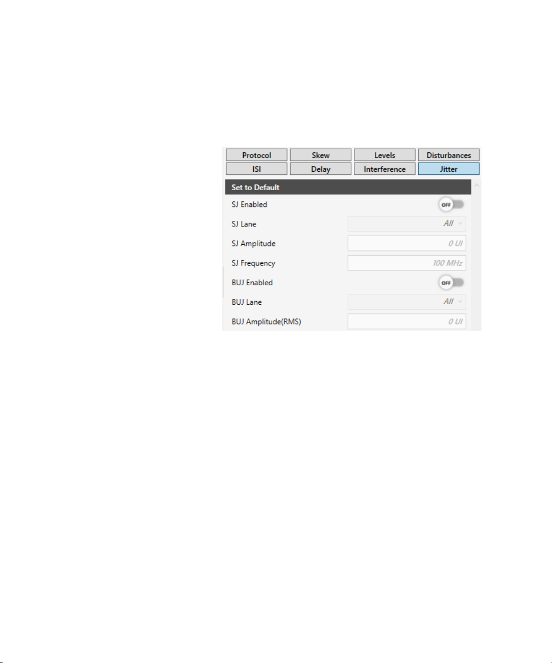
To change the jitter settings, click Jitter on the right panel to view the
corresponding settings (See Figure 13).
Figure 13 MIPI® C-PHY Parameters - Jitter Group
The parameters in the Jitter group generate Sinusoidal Jitter and
Bounded Uncorrelated Jitter (Random Jitter). For both types of jitter, it is
possible to select the target lane where they must be generated.
The parameters in this group are:
SJ Enabled
Enables or disables the Sinusoidal Jitter generation on all lanes.
SJ Lane
Select the lane where the Sinusoidal Jitter is applied.
It supports Sinusoidal Jitter on the Clock lane, on all Data lanes or
alternatively on a specific Data lane.
Keysight N5991MC2E MIPI® C-PHY Frame Generator User Guide 37

3 Using the Software
SJ Amplitude
Amplitude of the Sinusoidal Jitter in peak-to-peak.
SJ Frequency
Frequency of the Sinusoidal Jitter.
38 Keysight N5991MC2E MIPI® C-PHY Frame Generator User Guide

BUJ Enabled
Enables or disables the Bounded Uncorrelated Jitter generation on all
lanes. It emulates random jitter.
BUJ Lane
Select the lane where the Bounded Uncorrelated Jitter is applied.
It supports Bounded Uncorrelated Jitter on the Clock lane, on all Data
lanes or alternatively on a specific Data lane.
BUJ Amplitude(RMS)
Root Mean Square (RMS) Amplitude of the Bounded Uncorrelated Jitter.
Using the Software 3
Keysight N5991MC2E MIPI® C-PHY Frame Generator User Guide 39

3 Using the Software
40 Keysight N5991MC2E MIPI® C-PHY Frame Generator User Guide

Keysight N5991MC2E MIPI® C-PHY Frame Generator
User Guide
4 Troubleshooting
Support Information / 42
Using Logs / 43
4 Using the Software
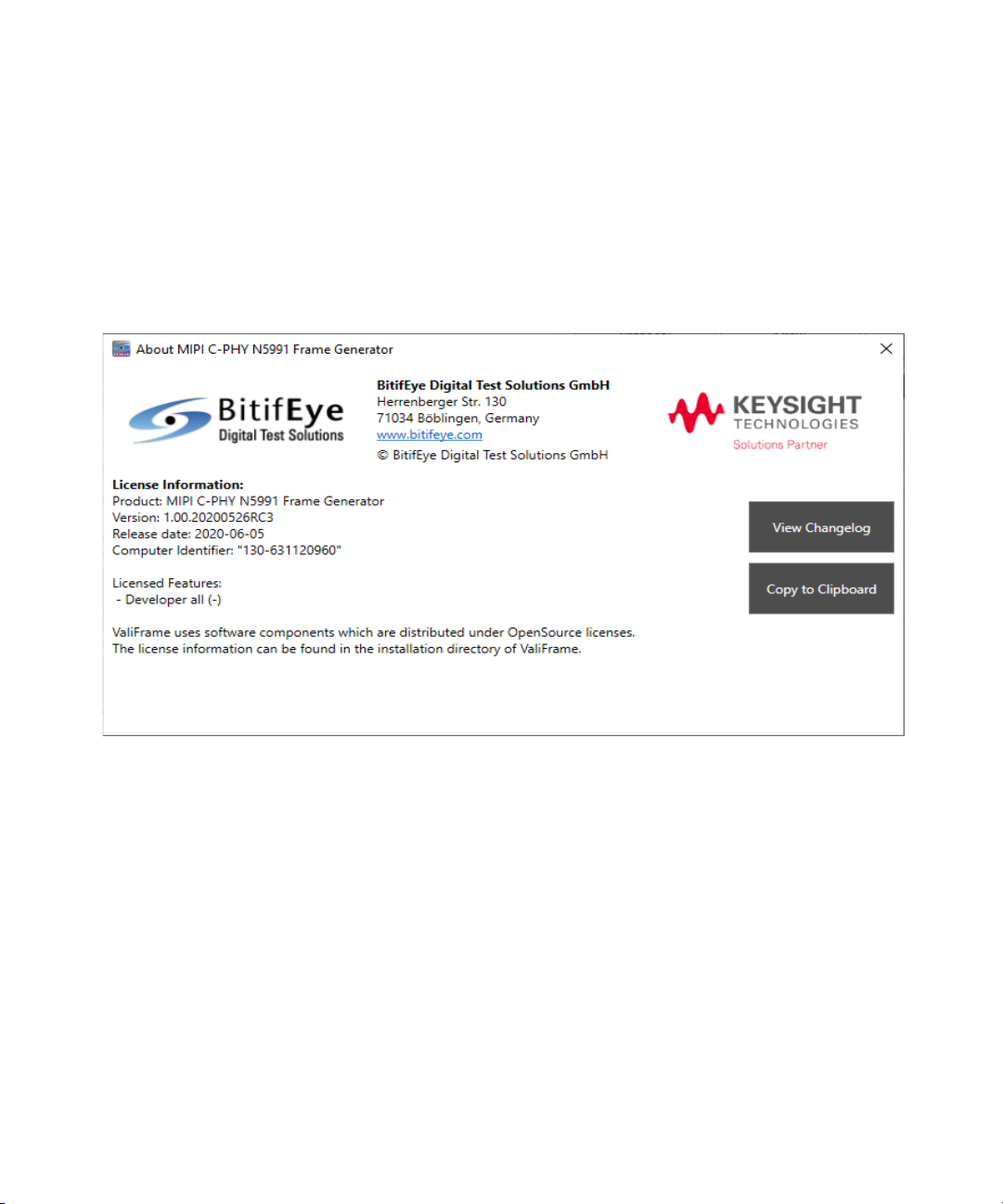
Support Information
If you experience issues with the software, send an email to
mipi-support@bitifeye.com. You must mention the version number, which
you can find in the About dialog box. To access it, click ABOUT... from the
main menu.
Figure 14 About the MIPI® C-PHY Frame Generator
42 Keysight N5991MC2E MIPI® C-PHY Frame Generator User Guide

Using Logs
Using the Software 4
Right click the Logger panel, select Show Log File to view the logs, and
investigate the root cause of an issue.
Keysight N5991MC2E MIPI® C-PHY Frame Generator User Guide 43

This information is subject to
change without notice.
© Keysight Technologies 2020
Edition 1.0, June 2020
www.keysight.com
 Loading...