

Keysight MX0023A InfiniiMax RC
Probe Amplifier and Probe Heads
User’s Guide

Notices
CAUTION
WARNING
© Keysight Technologies, 2020, 2022
No part of this manual may be reproduced in
any form or by any means (including electronic storage and retrieval or translation
into a foreign language) without prior agreement and written consent from Keysight
Technologies, Inc. as governed by United
States and international copyright laws.
Manual Part Number
MX0023-97000
Edition
Third Edition, April 2022
Published by:
Keysight Technologies, Inc.
1900 Garden of the Gods Road
Colorado Springs, CO 80907 USA
Warranty
The material contained in this document is provided “as is,” and is subject
to being changed, without notice, in
future editions. Further, to the maximum extent permitted by applicable
law, Keysight disclaims all warranties,
either express or implied, with regard
to this manual and any information
contained herein, including but not
limited to the implied warranties of
merchantability and fitness for a particular purpose. Keysight shall not be
liable for errors or for incidental or
consequential damages in connection
with the furnishing, use, or performance of this document or of any information contained herein. Should
Keysight and the user have a separate
written agreement with warranty terms
covering the material in this document
that conflict with these terms, the warranty terms in the separate agreement
shall control.
Technology Licenses
The hardware and/or software described in
this document are furnished under a license
and may be used or copied only in accordance with the terms of such license.
U.S. Government Rights
The Software is "commercial computer software," as defined by Federal Acquisition
Regulation ("FAR") 2.101. Pursuant to FAR
12.212 and 27.405-3 and Department of
Defense FAR Supplement ("DFARS")
227.7202, the U.S. government acquires
commercial computer software under the
same terms by which the software is customarily provided to the public. Accordingly,
Keysight provides the Software to U.S. government customers under its standard commercial license, which is embodied in its
End User License Agreement (EULA), a copy
of which can be found at
http://www.keysight.com/find/sweula. The
license set forth in the EULA represents the
exclusive authority by which the U.S. government may use, modify, distribute, or disclose the Software. The EULA and the
license set forth therein, does not require or
permit, among other things, that Keysight:
(1) Furnish technical information related to
commercial computer software or commercial computer software documentation that
is not customarily provided to the public; or
(2) Relinquish to, or otherwise provide, the
government rights in excess of these rights
customarily provided to the public to use,
modify, reproduce, release, perform, display, or disclose commercial computer software or commercial computer software
documentation. No additional government
requirements beyond those set forth in the
EULA shall apply, except to the extent that
those terms, rights, or licenses are explicitly
required from all providers of commercial
computer software pursuant to the FAR and
the DFARS and are set forth specifically in
writing elsewhere in the EULA. Keysight
shall be under no obligation to update,
revise or otherwise modify the Software.
With respect to any technical data as
defined by FAR 2.101, pursuant to FAR
12.211 and 27.404.2 and DFARS 227.7102,
the U.S. government acquires no greater
than Limited Rights as defined in FAR 27.401
or DFAR 227.7103-5 (c), as applicable in any
technical data. 52.227-14 (June 1987) or
DFAR 252.227-7015 (b)(2) (November
1995), as applicable in any technical data.
Safety Notices
A CAUTION notice denotes a hazard.
It calls attention to an operating
procedure, practice, or the like that,
if not correctly performed or
adhered to, could result in damage
to the product or loss of important
data. Do not proceed beyond a CAU-
TION notice until the indicated conditions are fully understood and
met.
A WARNING notice denotes a hazard. It calls attention to an operating procedure, practice, or the like
that, if not correctly performed or
adhered to, could result in personal
injury or death. Do not proceed
beyond a WARNING notice until the
indicated conditions are fully
understood and met.

Contents
1 MX0023A Probe Amplifier - Overview
2 Available Probe Heads and Accessories - Overview
Introduction 8
MX0023A Key Features 10
Compatibility with Keysight Oscilloscopes 11
Introduction to Supported Probe Heads 14
When to Use Which Probe Head 16
Other Recommended Accessories and Kits 19
N5450B Extreme Temperature Cable Extension Kit 19
N2880A InfiniiMax In-Line Attenuator Kit 19
N2881A InfiniiMax DC Blocking Capacitors 20
MX0102A Soldering Toolkit 20
N2852A AutoProbe II to AutoProbe III Adapter 23
MX0104A Performance Verification and Deskew Fixture Kit 23
N5448B (25cm) / N2823A (1m) Coaxial Phase Matched Cable Pair 24
N2812B (1m) High Performance Input Cable 24
E2669B Differential Connectivity Kit 25
3 Safety and Regulatory Information
Safety Checks and Warnings 28
Instrument Markings and Symbols 30
4 Proper Handling of Probe Amplifier and Probe Heads
Avoiding Damage and Costly Repairs 32
Using a static-safe workstation 32
Probe Amplifier and Probe Heads Handling Precautions 34
Precautions for the Probe Amplifier 34
Precautions for the Probe Cable 34
Precautions while Connecting and Disconnecting Probe Heads 35
Safely Connecting/Disconnecting the Probe Amplifier and Oscilloscope 35
Safely Connecting/Disconnecting the Probe Amplifier and Probe Head 35
Moving the Probing Setup to Different Probing Locations 35
Strain Relieving Techniques for Probe Heads 37
Tack-putty 38
Low-temperature hot glue 38
3

Velcro Pads 39
Tips for Soldering Probe Heads 40
Cleaning 41
5 Characteristics and Specifications
MX0023A Probe Amplifier Warranted Specifications 44
MX0023A Probe Amplifier Characteristics 45
InfiniiMax RC Probe Heads Characteristics 47
Environmental and General Characteristics 48
6 MX0100A InfiniiMax Micro Probe Head
Overview 50
MX0100A Probe Head Kit Components 51
MX0100A Dimensions 51
MX0100A Input Impedance 53
Setting up and Using the MX0100A Probe Head 56
Trimming the Lead Wires of MX0100A Probe Head 56
Soldering an MX0100A Probe Head to DUT 57
Maintaining the MX0100A Probe Head 60
MX0100A Probe Head Handling Precautions 60
Replacing the MX0100A Probe Tip Lead Wires 63
Extreme Temperature Testing with the MX0100A Probe Head 66
7 MX0106A InfiniiMax Differential Solder-in Probe Head
Overview 68
MX0106A Probe Head Supplied Accessories 68
MX0106A Dimensions 68
MX0106A Input Impedance 70
Setting up and Using the MX0106A Probe Head 73
Adjusting the Spacing between MX0106A Wires 73
Installing / Replacing the MX0106A Probe Head Wire Leads 73
Connecting the MX0106A Probe Head to DUT 77
Soldering the MX0106A Probe Head to DUT 78
Extreme Temperature Testing with the MX0106A Probe Head 79
8 N2839A InfiniiMax II Browser Probe Head
Overview 82
N2839A Browser Probe Head Components 82
N2839A Supplied Accessories 82
N2839A Dimensions 84
N2839A Input Impedance 84
Using the N2839A Browser Probe Head 88
4 InfiniiMax RC Probe Amplifier and Probe Heads User’s Guide

Adjusting Spacing Between the Browser Tips 88
Hands-Free Probing 88
Maintaining the N2839A Probe Head 90
N2839A Probe Head Handling Precautions 90
Location of Serial Number 90
Replacing the Browser’s Tips 91
9 MX0105A InfiniiMax Differential SMA Probe Head
Overview 94
MX0105A Probe Head Components 94
MX0105A Dimensions 96
MX0105A SPICE Subcircuit Data 97
MX0105A Input Return Loss (S11) 98
10 N5425B InfiniiMax Differential ZIF Probe Head
Overview 100
Supported ZIF Tips 100
N5425B Probe Head and ZIF Tips Dimensions 102
N5425B Input Impedance 104
SPICE Model of N5425B Probe Head with N5426A ZIF Tip Attached 105
SPICE Deck of N5425B Probe Head with N5426A ZIF Tip Attached 106
SPICE Model of the N5426A ZIF Tip 108
SPICE Deck of N5426A ZIF Tip 109
Using the N5425B Probe Head with N5426A ZIF Tips 111
Using the N5425B Probe Head with N2884A Fine Wire ZIF Tip 116
Maintaining the N5425B Probe Head 123
Fine Wire ZIF Tips Handling Precautions 123
11 Configuring Infiniium Software for Probe Amplifier and Probe Heads
Selecting Components Used in the Probing Setup 126
Configuring Offset Behavior 129
Calibrating your InfiniiMax RC Probe 131
Calibration Overview 131
Performing DC Gain / Offset and Skew Calibration 132
12 Making Measurements
Probing Single-ended Signals using a Differential Probe Head 138
Extreme Temperature Probing 139
InfiniiMax RC Probe Heads Supporting Extreme Temperature Testing 139
Probe Heads Discoloration 139
Cautions Associated with Extreme Temperature Testing 140
Probing Ungrounded Devices 141
InfiniiMax RC Probe Amplifier and Probe Heads User’s Guide 5

Blocking out the DC Component of the Input Signal 142
13 InfiniiMax RC Probe Amplifier and Probe Heads System Responses
Typical Corrected System Frequency Response 144
Typical Step Response of Corrected System 145
Typical CMRR 146
14 Performance Verification
Before you Start 150
Recommended Test Interval 150
To Test Bandwidth 151
Required Test Equipment 151
Procedure 152
To Test Input Resistance 157
Required Test Equipment 157
Procedure 157
Performance Test Record 161
15 Returning a Probe/Probe Head for Repair/Service
Contacting Keysight Technologies for Technical Assistance 164
16 Replacement Parts
Index
MX0100A Probe Head 165
MX0106A Probe Head 165
N2839A Browser Head 166
Other Replacement Parts 166
6 InfiniiMax RC Probe Amplifier and Probe Heads User’s Guide

Keysight InfiniiMax RC Probe Amplifier and Probe Heads
User’s Guide
1 MX0023A Probe Amplifier -
Overview
Introduction 8
MX0023A Key Features 10
Compatibility with Keysight Oscilloscopes 11
7

1 MX0023A Probe Amplifier - Overview
Output Connector
(with AutoProbe II
Connection to
Oscilloscope)
Probe Head Connector
Menu Button
Polarity
Markings
Channel Identification Rings
Ground Connection
Introduction
The MX0023A InfiniiMax RC probe amplifier provides high bandwidth of up to 25
GHz and an RC input impedance profile for extremely low mid-band loading,
which is necessary to address modern high-speed probing requirements.
This probe amplifier supports a wide variety of flexible connectivity solutions,
covering today's emerging signaling standards such as DDR5/LPDDR5 and other
high-speed signal debug and validation test needs.
With an extensive range of supported probe heads and accessories, this probe
amplifier caters to most of the probing situations including harder to probe small
geometry target devices and extreme environment testing.
8 InfiniiMax RC Probe Amplifier and Probe Heads User’s Guide
Figure 1 MX0023A Probe Amplifier
Table 1 MX0023A Probe Amplifier Components
Probe Amplifier Component Description/Usage
Output Connector
(with AutoProbe II Connection to
Oscilloscope)
Menu Button Press this button to bring up the Infiniium GUI’s Probe
The probe amplifier uses the Keysight AutoProbe II (3.5 mm)
interface that allows it to connect directly to a compatible
Keysight oscilloscope (see page 11 ).
The oscilloscope’s AutoProbe interface provides the probe power,
probe offset, and auto configuration of probe type and attenuation
setting on connection.
Configuration dialog box on the oscilloscope. Use this dialog box
to configure probe settings (see page 125 ).

MX0023A Probe Amplifier - Overview 1
Table 1 MX0023A Probe Amplifier Components
Probe Amplifier Component Description/Usage
Channel Identification Rings When multiple probes are connected to the oscilloscope, use the
channel identification rings to associate the channel inputs with
each probe. Place one colored ring near the probe’s output
connector and place an identical color ring near the probe head
connector.
Polarity Markings Polarity markings to indicate the positive (+) and negative (-)
inputs of the probe amplifier.
Probe Head Connector Use this connector to connect your probe amplifier to one of the
supported probe heads (see page 14).
Ground Connection Allows you to connect the DUT ground to the probe amplifier
ground using a ground lead wire.
This is needed if the DUT is not grounded to the oscilloscope via
the AC mains ground (see page 141).
InfiniiMax RC Probe Amplifier and Probe Heads User’s Guide 9

1 MX0023A Probe Amplifier - Overview
MX0023A Key Features
Yielding Accurate
Measurements
“RC" Input
Impedance
Architecture
Two Input
Attenuation
Ranges
The MX0023A probe amplifier has built-in probe specific s-parameter correction
filter to ensure a flat frequency response. This unique s-parameter of the probe
amplifier is used with the s-parameters of various supported probe heads to
further flatten the magnitude and phase response of the probe for high accuracy
measurements. Each probe head has different s-parameters stored in the
oscilloscope’s firmware. On selecting the probe head in the oscilloscope’s
software, the appropriate s- parameters for the probe head are used in conjunction
with the probe amplifier’s s-parameters to compute the overall probe correction
for your measurement case.
The probe amplifier’s RC architecture makes it suitable for probing buses that
transition to a “high Z” state or for probing signals with high impedance.
The probe amplifier supports the following two flexible input dynamic ranges.
• 600mVpp @1:1
•2.5Vpp @4:1
The input range is automatically configured depending on the vertical scale of the
oscilloscope.
AC Calibration
Mode
High Bandwidth
Probing
Requirements
Applicable
System
Bandwidth
10 InfiniiMax RC Probe Amplifier and Probe Heads User’s Guide
The probe amplifier supports the Vout/Vin calibration to accurately show the
voltage at the tip of the probe (Vout/Vin) as loaded by the probe. VIn represents a
new signal with the probe’s effect included (the voltage at the probe’s tip), and
Vout represents the signal as passed through the probe.
The probe amplifier efficiently fulfills the probing bandwidth requirements
between 6-25 GHz. For instance, it is best suited for serial links operating up to 12
Gbps that require the probe bandwidth up to 25 GHz.
For any combination of a probe head with the MX0023A probe amplifier, the
applicable system bandwidth is the lesser of the supported bandwidths of the
probe head or the probe amplifier. The MX0023A supports 25 GHz bandwidth.
Therefore, if, for example, you use it with the MX0106A probe head, which
supports a 23 GHz bandwidth, then this combination would produce a system
with a 23 GHz bandwidth.

Compatibility with Keysight Oscilloscopes
NOTE
Compatible Oscilloscope Adapter Required
Infiniium Oscilloscopes with AutoProbe II Interface
UXR-Series (13-33 GHz models) none 10.25 or higher
90000 Q, V, X, Z-Series none 6.55 or higher
Infiniium Oscilloscopes with AutoProbe III Interface
MX0023A Probe Amplifier - Overview 1
Required Infiniium
Software Version
UXR-Series (40 GHz or higher
models)
N2852A AutoProbe II to AutoProbe
III Adapter
(Visit
http://www.keysight.com/find
/N2852A to know more about this
adapter.)
10.25 or higher
The MX0023A probe amplifier is NOT compatible with Infiniium 9000
Series, InfiniiVision, or any previous generation Keysight oscilloscopes.
Is your oscilloscope software up-to-date?
Keysight periodically releases software updates to support your probe, fix known defects, and
incorporate product enhancements. To download the latest firmware, go to www.Keysight.com and
search for your oscilloscope’s model number. Click the “Drivers, Firmware & Software” tab under the
Technical Support link.
InfiniiMax RC Probe Amplifier and Probe Heads User’s Guide 11

1 MX0023A Probe Amplifier - Overview
12 InfiniiMax RC Probe Amplifier and Probe Heads User’s Guide

Keysight InfiniiMax RC Probe Amplifier and Probe Heads
User’s Guide
2 Available Probe Heads and
Accessories - Overview
Introduction to Supported Probe Heads 14
When to Use Which Probe Head 16
Other Recommended Accessories and Kits 19
N5450B Extreme Temperature Cable Extension Kit 19
N2880A InfiniiMax In-Line Attenuator Kit 19
N2881A InfiniiMax DC Blocking Capacitors 20
MX0102A Soldering Toolkit 20
N2852A AutoProbe II to AutoProbe III Adapter 23
MX0104A Performance Verification and Deskew Fixture Kit 23
N5448B (25cm) / N2823A (1m) Coaxial Phase Matched Cable Pair 24
N2812B (1m) High Performance Input Cable 24
E2669B Differential Connectivity Kit 25
This chapter provides an overview of various probe heads and accessories that are
compatible for use with the MX0023A probe amplifier.
13

2 Available Probe Heads and Accessories - Overview
NOTE
Introduction to Supported Probe Heads
A probe amplifier connects to a DUT via a probe head.
When using the MX0023A probe amplifier, you can choose from a wide variety of
probe heads and accessories to support your specific probing and DUT
connectivity requirements.
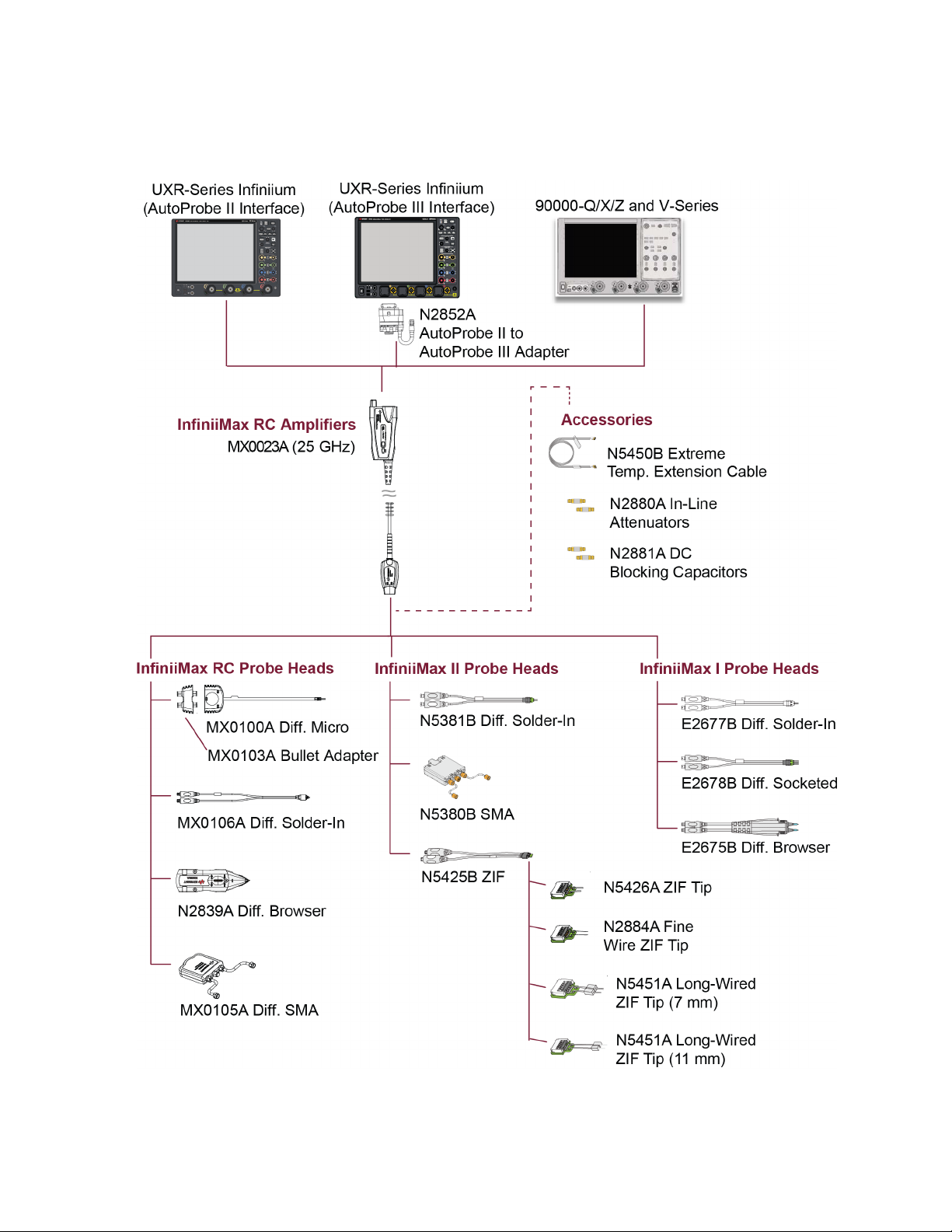
The probe heads supported for MX0023A are primarily categorized as follows:
Probe Head Where to Find Detailed Information
New InfiniiMax RC Probe Heads
(supporting higher bandwidths up to
25 GHz)
Existing InfiniiMax I and II Probe Heads
(supporting bandwidths up to 12 GHz)
Detailed information on each of these probe heads is
available as separate chapters in this guide.
Most of the existing InfiniiMax I and II probe heads are
compatible for use with the MX0023A probe amplifier (see
Figure 2 on page 15).
Detailed information on each of these probe heads is
available in the Keysight 1168/9B-Series Differential and
Single-Ended Probes user’s guide.
This guide is available for download from the Document
Library tab on www.keysight.com/find/1169B.
InfiniiMax III and III+ probe heads are NOT compatible for use with the
MX0023A probe amplifier.
The following figure displays these supported probe heads and accessories for
MX0023A.
14 InfiniiMax RC Probe Amplifier and Probe Heads User’s Guide
Available Probe Heads and Accessories - Overview 2
Figure 2 MX0023A Probe Family Diagram
InfiniiMax RC Probe Amplifier and Probe Heads User’s Guide 15
2 Available Probe Heads and Accessories - Overview
When to Use Which Probe Head
The following table provides a high-level comparison of the supported probe
heads to help you assess when to use which probe head with MX0023A.
These probe heads are listed in the order of their maximum supported bandwidth
when used with the MX0023A probe amplifier.
Table 2 Supported Probe Heads (Sheet 1 of 3)
Probe Head (listed in the order of BW) Recommended Usage Bandwidtha
1. MX0100A InfiniiMax Micro Probe Head (refer to page 49 for details)
• Light, flexible, and smallest solder-in head
25 GHz 0.17 pF 0.26 pF
• Best suited for providing uncompromised
access to small geometry, high-density
fine-pitch targets
• Recommended for high-speed signaling
standards DDR4, DDR5, LPDDR4, LPDDR5,
MIPI D-Phy 2.0/3.0, C-Phy, and M-Phy
2. MX0106A Differential Solder-in Probe Head (refer to page 67 for details)
• The most reliable semi-permanent signal
access for high fidelity measurement
23 GHz 0.17 pF 0.29 pF
• Hands-free access to fine-pitch
components in high-density electronics
• Recommended for MIPI D-Phy 2.0 and
C-Phy 2.0
3. N2839A InfiniiMax II Browser Probe Head (refer to page 81 for details)
• Hand-held browsing for general purpose
troubleshooting of a circuit board
21 GHz 0.20 pF 0.34 pF
• Adjustable probe tips for different circuit
geometries
Cdiff
(pF)
b
Cse
(pF)
c
4. MX0105A Differential SMA Probe Head (refer to page 93 for details)
• Suitable for differential cabled
measurement using only one channel of the
oscilloscope
20 GHz N/A N/A
• Offset matched SMA cables adapt to
variable spacing
• Ideal for signaling standards such as HDMI
and MIPI Mphy that require termination to a
common DC voltage (± 4 V) rather than a
ground
16 InfiniiMax RC Probe Amplifier and Probe Heads User’s Guide

Table 2 Supported Probe Heads (Sheet 2 of 3)
Available Probe Heads and Accessories - Overview 2
Probe Head (listed in the order of BW) Recommended Usage Bandwidtha
5. N5425B Differential ZIF Probe Head (refer to page 99 for details)
• Ideal for probing multiple signals in tight
spaces such as DDR memory
• ZIFs can be installed at multiple locations
on your DUT
• Ideal for hard to reach, small fine pitch
targets
• ZIF feature allows connection without
compressing the delicate wires which
cannot support this compression
With N5426A ZIF Tip
18 GHz 0.33 pF 0.53 pF
N2884A Fine Wire ZIF Tip
18 GHz 0.35 pF N/A
• Recommended for DDR4, DDR5, LPDDR4,
MIPI D-Phy 2.0 and C-Phy 2.0
6. N5381B Differential Solder-in Probe Head (refer to 1168/9B-Series Probes user’s guide)
• Solder-in hands free connection
12 GHz 0.21 pF 0.35 pF
• Recommended for DDR4, DDR5, LPDDR4,
MIPI D-Phy 2.0
Cdiff
(pF)
b
Cse
(pF)
c
7. N5380B Differential SMA Probe Head (refer to 1168/9B-Series Probes user’s guide)
• Suitable for differential cabled
measurement using only one channel of the
oscilloscope
12 GHz N/A N/A
• Offset matched SMA cables adapt to
variable spacing
• Ideal for signaling standards such as HDMI
and MIPI Mphy that require termination to a
common DC voltage (± 4 V) rather than a
ground
Note: The plastic housing on the N5380B
needs to be removed to mate with the
MX0023A amplifier. Refer to the
1168/9B-Series Probes user's guide for
details of this removal procedure.
InfiniiMax RC Probe Amplifier and Probe Heads User’s Guide 17
2 Available Probe Heads and Accessories - Overview
Table 2 Supported Probe Heads (Sheet 3 of 3)
Probe Head (listed in the order of BW) Recommended Usage Bandwidtha
8. N5425B ZIF Probe Head with Long Wire ZIF Tips (refer to 1168/9B-Series Probes user’s guide)
• The long-wired ZIF tips connection is ideal
for variable pitch targets, including larger
pitches
• Ideal for probing multiple signals in tight
spaces such as DDR memory
• ZIFs can be installed at multiple locations
on your DUT
With 7mm N5451A ZIF Tip
~9.9 GHz
(0º tip span)
~4.4 GHz
(60º tip span)
With 11mm N5451A ZIF Tip
• ZIF feature allows connection without
compressing the delicate wires which
cannot support this compression
• Recommended for DDR4, DDR5, LPDDR4,
MIPI D-Phy 2.0 and C-Phy 2.0
9. E2677B Differential Solder-in Probe Head (refer to 1168/9B-Series Probes user’s guide)
~5 GHz
(0º tip span)
~3.3 GHz
(60º tip span)
• Hands-free solder-in connection 12 GHz 0.27 pF 0.44 pF
b
Cdiff
(pF)
0.6 pF 0.58 pF
0.68 pF 0.68 pF
Cse
(pF)
c
10. E2678B Differential Socketed Probe Head (refer to 1168/9B-Series Probes user’s guide)
• Measuring signal via a plug-on socket
connection
12 GHz 0.34 pF 0.56 pF
• Removable connection using solder-in
resistor pins for hard to reach targets
11. E2675B Differential Browser Probe Head (refer to 1168/9B-Series Probes user’s guide)
• Hand-held browsing for general purpose
troubleshooting of a circuit board
a The bandwidth listed in this table is the maximum bandwidth supported by each probe head. For any combination of a probe head with a probe
amplifier, the applicable bandwidth is the lesser of the supported bandwidths of the probe head or the probe amplifier. For example, using the
MX0023A, which supports a 25 GHz bandwidth, with a MX0106A, which supports a 23 GHz bandwidth, would produce a system with a 23 GHz
bandwidth.
b Capacitance seen by differential signals
c Capacitance seen by single-ended signals
6 GHz 0.32 pF 0.57 pF
18 InfiniiMax RC Probe Amplifier and Probe Heads User’s Guide
Available Probe Heads and Accessories - Overview 2
Attenuator
Other Recommended Accessories and Kits
In addition to the probe heads listed in the previous section, there are a number of
kits and accessories available for use with the MX0023A probe amplifier.
This section provides an overview to these recommended accessories and kits. You
can either order these at the time of ordering the probe amplifier or separately
later.
N5450B Extreme Temperature Cable Extension Kit
The N5450B extreme temperature cable extension kit
allows you to use the MX0023A probe amplifier to probe a
device in an environment chamber.
The MX0023A probe amplifier has an operating
temperature range from 5
subjected to extreme temperatures. But a few probe heads
can be operated over a much larger range of temperatures.
The N5450B extension cables allow you to physically
separate the amplifier from the probe head so that the
probe head can be operated inside a temperature chamber while the probe
amplifier remains outside the chamber.
o
C to 40o C and cannot be
Refer to the topic “Extreme Temperature Probing" on page 139 to know more.
Table 3 N5450B Kit Contents
Item Qty Supplied Description
Phase-matched RF
Cables
Coupling Tag 1 A coupling tag is included with the cables to ensure
2 To ensure a high-quality measurement, the N5450B
N2880A InfiniiMax In-Line Attenuator Kit
The N2880A In-Line Attenuators allow you to increase the maximum input range
and offset range of the MX0023A probe amplifier so that you can measure signals
larger than the probe’s maximum input range and offset range.
cable set have been phase-matched at the factory.
that the cables stay as a matched pair.
Figure 3 Attenuators Between a Probe Amplifier and a Probe Head
InfiniiMax RC Probe Amplifier and Probe Heads User’s Guide 19
2 Available Probe Heads and Accessories - Overview
DC Blocking Capacitor
Table 4 N2880A Kit Contents
Item Qty Supplied Description
6 dB Attenuators 2 These attenuators come as matched pairs and should only be
12 dB Attenuators 2
20 dB Attenuators 2
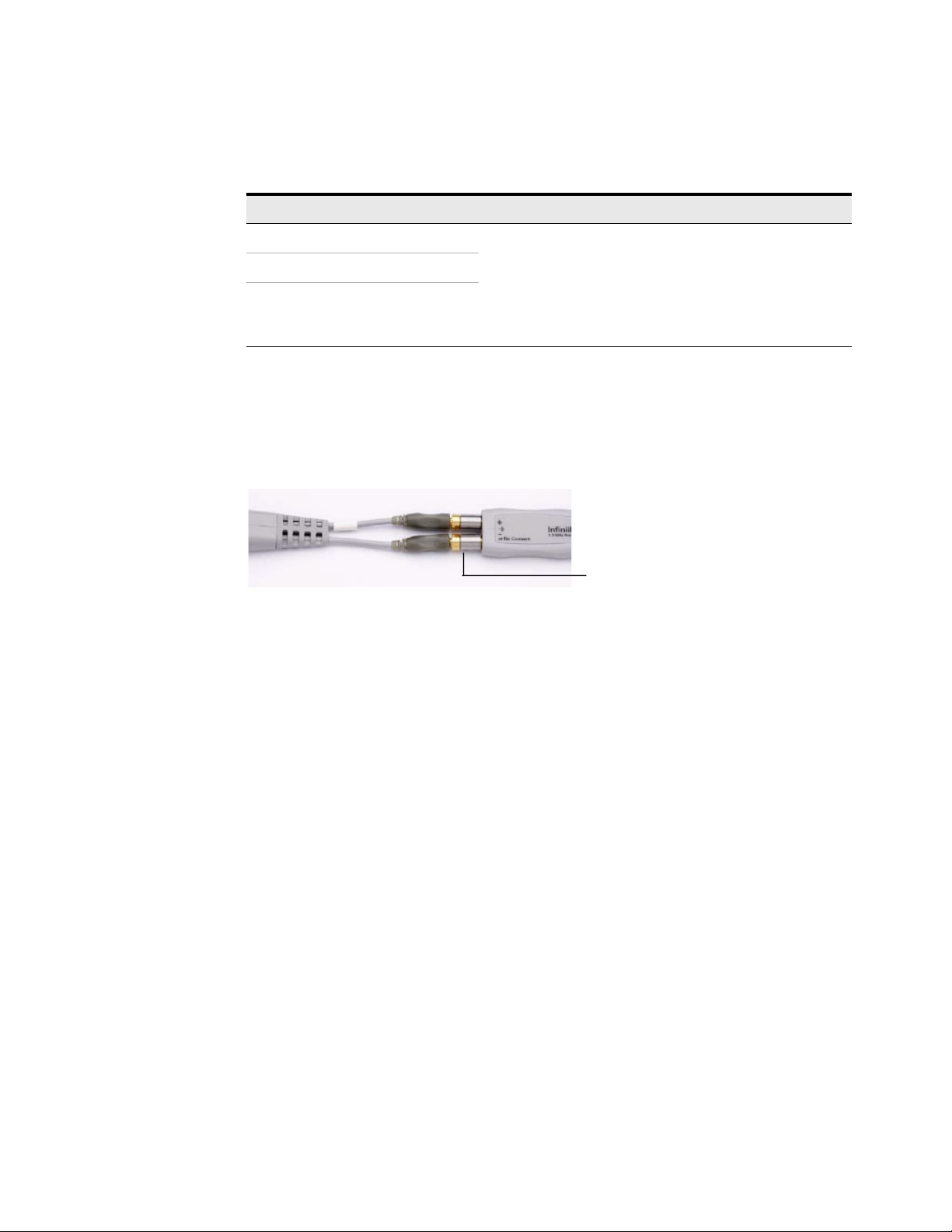
N2881A InfiniiMax DC Blocking Capacitors
The N2881A InfiniiMax DC Blocking Capacitors block out the DC component of the
input signal (up to 30 Vdc). You can place these between the MX0023A probe
amplifier and probe head as shown in the picture below.
used with each other. Each attenuator has a serial number.
The pair of matching attenuators in each set will have the
same four digit numeric prefix and will differ by the last letter
(one attenuator in the matched pair will be labeled A and the
other will be labeled B).
Figure 4 Placement of DC Blocking Capacitor Between a Probe Amplifier and a Probe Head
You can also use these DC blocking capacitors with the N2880A In-Line
Attenuators. The order of the two products in the probing system (that is, which
one is closer to the probe amplifier) does not matter.
Refer to the topic “Blocking out the DC Component of the Input Signal" on
page 142 to know more.
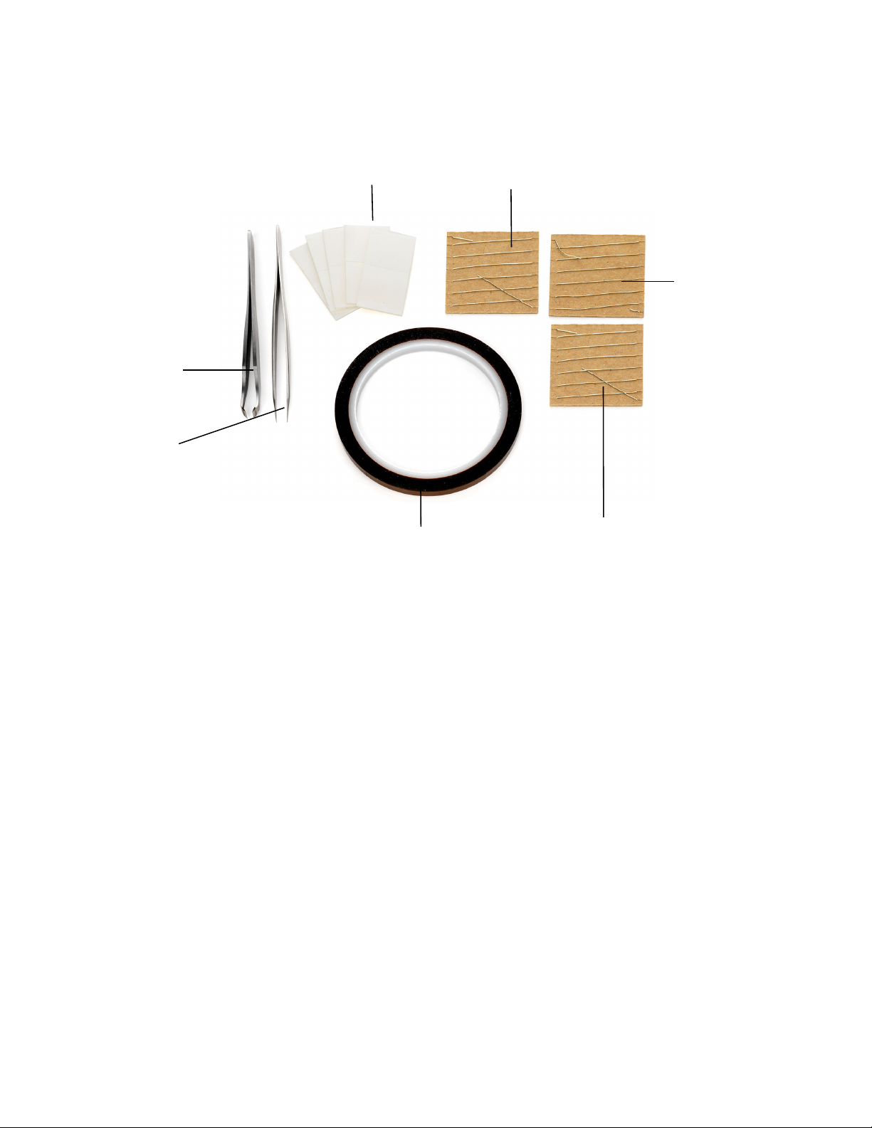
MX0102A Soldering Toolkit
The MX0102A soldering toolkit provides tools that can make soldering tasks
easier. For instance, you can use the tools available in this kit while soldering the
lead wires of the MX0100A Micro probe head to a DUT (see page 57 for details).
20 InfiniiMax RC Probe Amplifier and Probe Heads User’s Guide
Available Probe Heads and Accessories - Overview 2
Straight
Tweezers
Cutting
Tweezer s
Double-sided Foam Tape
Low Temperature
Solder Wire
Regular Solder Wire
Probe Tip Wire
Kapton Tape
Figure 5 MX0102A soldering toolkit contents
InfiniiMax RC Probe Amplifier and Probe Heads User’s Guide 21

2 Available Probe Heads and Accessories - Overview
Table 5 Accessories supplied in the soldering toolkit
Description
Straight Tweezers
(Anti-magnetic straight pointed tip 120mm)
For general purpose manipulation / movement of com-
ponents such as probe tip wires and probe head.
Cutting Tweezers
(Narrow oblique head 115mm)
To cut a probe tip wire to a desired length.
Kapton Tape (36 yards roll)
To provide strain-relief to the neck portion of the probe
head by taping it to a flat surface (such as a DUT circuit
board).
Double-sided Foam Tape
To provide strain-relief to either the neck portion of the
probe head or the plastic housings by taping it to a flat
surface such as a tabletop or a DUT circuit board.
Regular Solder Wire
Lead free, .009" diameter, 2 feet long
To attach the probe tip wires to a DUT using standard
lead-free soldering temperatures (330 °C to 350 °C).
(NOTE: This alloy melts at 217
o
C.)
Qty
Supplied
Part
Number
a
1 8710-2837
1 8710-2838
1 0460-3121
10 0460-3122
1 MX0102-21302
Low Temperature Solder Wire
1 MX0102-21303
Lead free, .010" diameter, 2 feet long
To attach the probe tip wires to a DUT using a low tem-
perature setting on your soldering iron.
(NOTE: This alloy melts at 138
Probe Tip Wire
o
C.)
1 MX0102-21301
.004" diameter, 2 feet long
To add ground wires to your probe tip if InfiniiMode mea-
surements (differential, single ended, and common
mode signals with a single probe tip) are desired. Clip as
short as possible using the cutting tweezers included in
the kit.
a You can reorder these items using the part numbers included in the table above.
22 InfiniiMax RC Probe Amplifier and Probe Heads User’s Guide

Available Probe Heads and Accessories - Overview 2
CAUTION
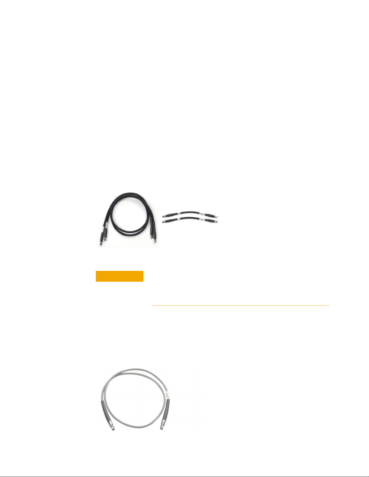
N2852A AutoProbe II to AutoProbe III Adapter
This adapter allows you to connect the MX0023A probe
amplifier that has the AutoProbe II interface to the
Keysight UXR-Series (40 GHz or higher) Infiniium
oscilloscope that has the AutoProbe III interface.
To know more about the N2852A adapter, visit
http://www.keysight.com/find/N2852A and then
download the adapter’s user’s guide available in the
Document Library tab.
Care should be taken while handling the N2852A adapter's RF
cable. Avoid bending this cable backwards or kinking the cable to
ensure measurements accuracy.
MX0104A Performance Verification and Deskew Fixture Kit
The MX0104A PV/Deskew fixture helps you to calibrate /
deskew or verify the performance of your MX0023A
probe amplifier.
Table 6 MX0104A Kit Contents
Item Qty Supplied
50Ω SMA Terminator 1
Deskew Fixture 1
The MX0104A fixture is used with the following two components to promote the
proper positioning of the probe during the deskew/PV procedure.
Table 7 MX0104A Optional Components
Option Usage
N2787A 3D
Probe
Positioner
For more sophisticated probe head positioning
Highly recommended for MX0023A probe amplifier.
Also, highly recommended when using probe heads such
as the browser probe head to hold the browser in place.
Option 001:
Performance
Verification
Stand
InfiniiMax RC Probe Amplifier and Probe Heads User’s Guide 23
For convenient, handy, and low-cost probe head
positioning
Recommended for use with InfiniiMax III/III+ probe
amplifiers and heads only
2 Available Probe Heads and Accessories - Overview
CAUTION
• To know how to use this fixture for deskew/calibration of your probe, refer to
the chapter “Performing DC Gain / Offset and Skew Calibration" on page 132.
• To know how to use this fixture for performance verification of your probe, refer
to the chapter “Performance Verification" on page 149.
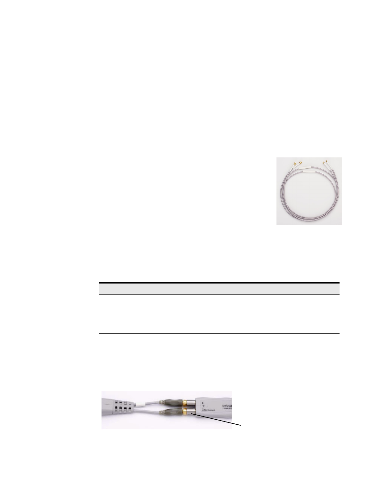
N5448B (25cm) / N2823A (1m) Coaxial Phase Matched Cable Pair
The N5448B (25cm) / N2823A (1m) phase matched cable pair allows you to
extend the cable length of the MX0105A SMA probe head and add flexibility and
convenience to the probing setup. You can easily replace the supplied rigid cables
of the SMA probe head with these cables. These cables support 2.92 mm
male-to-2.92 mm male connection. Skew error between two cables are matched
to within 5 psec, and the cable supports up to 40 GHz.
For detailed specifications of these cables, refer to the user’s guide available in the
Document Library tab of www.keysight.com/find/N5448B.
Figure 6 N2823A and N5448B Coaxial Phased Matched Cable Pairs
The maximum bend radius for these coaxial cable pairs is 30 mm.
Bending these cables at too tight a radius or twisting the cables
can cause damage, reduce performance, and impact the
precision of these cables.
N2812B (1m) High Performance Input Cable
The N2812B input cable provides excellent flexibility, high quality measurements,
and a warranted bandwidth of 32 GHz. You can use this cable with the Infiniium V,
90000-X/Q, UXR <=33 GHz series oscilloscopes.
24 InfiniiMax RC Probe Amplifier and Probe Heads User’s Guide
E2669B Differential Connectivity Kit
The E2669B differential connectivity kit provides multiple quantities of the:
• following three InfiniiMax I probe heads supported for use with the MX0023A
probe amplifier.
• accessories needed for these three probe heads.
Available Probe Heads and Accessories - Overview 2
Figure 7 E2669B Differential Connectivity Kit (not to scale)
InfiniiMax RC Probe Amplifier and Probe Heads User’s Guide 25

2 Available Probe Heads and Accessories - Overview
NOTE
Table 8 E2669B Kit Contents
Probe Heads Included in the Kit
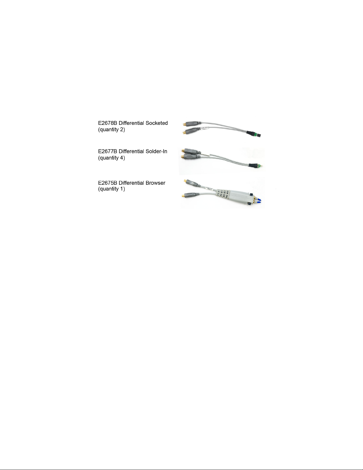
E2678B Differential Socketed Head 2
E2677B Differential Solder-In Head 4
E2675B Differential Browser 1
Qty
Supplied
Qty
Other Accessories Included in the Kit
160W damped wire accessory 12
82W resistor for full bandwidth 96
Socket for 25 mil (25/1000 inch)
square pins, female on both ends
25 mil female socket w/20 mil round
male pin on other end
Heat shrink socket accessory 8
Header adapter, 91W 4
82W resistor template 1
91W resistor for full bandwidth 80
150W resistor for medium bandwidth 40
91W resistor template 1
150W resistor template 1
Resistive tip (blue), 91W 20
Ergonomic handle 1
Supplied
8
8
E2678B E2677B E2675B
✓
✓
✓
✓
✓
✓
✓
Used With
✓
✓
✓
✓
Part Number
(Not orderable)
01130-21303
01130-81506
01131-85201
01131-85202
01130-41101
01130-63201
01131-94309
1NC3-1091
1NC3-1150
01131-94311
01131-94308
✓
✓
01131-62107
01131-43201
Resistor performance. The S2 resistors were changed from 100W to 91W
for slightly better performance. Either value produces a response that is
well within specifications. If you have some of the older 100W resistors,
ensure that you use either two 100W or two 91W resistors. Do not mix
them.
26 InfiniiMax RC Probe Amplifier and Probe Heads User’s Guide

Keysight InfiniiMax RC Probe Amplifier and Probe Heads
User’s Guide
3 Safety and Regulatory
Information
Safety Checks and Warnings 28
Instrument Markings and Symbols 30
27
3 Safety and Regulatory Information
WARNING
WARNING
WARNING
WARNING
WARNING
WARNING
Safety Checks and Warnings
This manual provides information and warnings essential for operating this probe
and probe heads in a safe manner and for maintaining these in safe operating
condition. To ensure safe operation and to obtain maximum performance from the
probe, carefully read and observe the following warnings, cautions, and notes.
These product have been designed and tested in accordance with accepted
industry standards, and have been supplied in a safe condition. The
documentation contains information and warnings that must be followed by the
user to ensure safe operation and to maintain these products in a safe condition.
Note the external markings on the products that are described in this document.
To avoid personal injury and to prevent fire or damage to these products or
products connected to these, review and comply with the following safety
precautions.
Use Only Grounded Instruments. Do not connect the probe’s ground lead to a
potential other than earth ground. Always make sure the probe and oscilloscope are
grounded properly. Before making connections to the input leads of this probe,
ensure that the probe’s output connector is attached to the channel input of the
oscilloscope and the oscilloscope is properly grounded.
Connect and Disconnect Properly.
See page 35 for the sequence in which connection/disconnection needs to be
done.
Observe Probe Voltage Ratings.
Do not apply any electrical potential to the probe input which exceeds the maximum
rating of the probe. See page 45 for maximum input voltage ratings.
These probe assemblies are NOT intended for measurements on mains circuits (CAT
II, CAT III, and CAT IV).
Indoor Use Only.
Do not operate in wet/damp environments. Keep product surfaces dry and clean.
Never leave the probe connected to a conductor while it is not connected to an
oscilloscope or voltage measuring instrument.
Periodically inspect the probe and probe wires to check for any damage.
Do Not Operate With Visible or Suspected Failures. If you suspect there is damage,
have it inspected by a Keysight authorized service personnel.
28 InfiniiMax RC Probe Amplifier and Probe Heads User’s Guide
Safety and Regulatory Information 3
WARNING
WARNING
WARNING
CAUTION
WARNING
WARNING
WARNING
WARNING
Do not operate the probe or oscilloscope in the presence of flammable gasses or
fumes. Operation of any electrical instrument in such an environment constitutes a
definite safety hazard.
If the probe/probe heads are used in a manner not specified by the manufacturer, the
protection provided by these may be impaired.
Do not install substitute parts or perform any unauthorized modification to the probe
amplifier / probe head.
Do not attempt internal service or adjustment. Service should be carried out by a
Keysight Technologies authorized service personnel. For any service needs, contact
Keysight Technologies. See page 163 to know more.
The probe cable is a sensitive part of the probe and, therefore, you should be careful
not to damage it through excessive bending or pulling. Avoid any mechanical shocks
to this product in order to guarantee accurate performance and protection.
Concerning the Oscilloscope or Voltage Measuring Instrument to Which
the Probe is Connected
Whenever it is likely that the ground protection is impaired, you must make the
instrument inoperative and secure it against any unintended operation.
If you energize the instrument by an auto transformer (for voltage reduction or
mains isolation), the ground pin of the input connector terminal must be connected
to the earth terminal of the power source.
Before turning on the instrument, you must connect the protective earth terminal of
the instrument to the protective conductor of the (mains) power cord. The mains
plug shall only be inserted in a socket outlet provided with a protective earth
contact. You must not negate the protective action by using an extension cord
(power cable) without a protective conductor (grounding). Grounding one conductor
of a two-conductor outlet is not sufficient protection.
Capacitors inside the instrument may retain a charge even if the instrument is
disconnected from its source of supply.
InfiniiMax RC Probe Amplifier and Probe Heads User’s Guide 29

3 Safety and Regulatory Information
Instrument Markings and Symbols
Symbol Description
This symbol indicates the Environmental Protection Use Period (EPUP)
for the product’s toxic substances for the China RoHS requirements.
Notice for the European Community: This product complies with the
WEEE Directive (2002/96/EC) marking requirements. The affixed label
indicates that you must not discard this electrical/electronic product in
domestic household waste.
Product Category: With reference to the requirement types in the WEEE
Directive Annex I, this product is classed as a “Monitoring and Control
Instrumentation” product.
Do not dispose in domestic household waste.
To return unwanted products, contact your local Keysight office.
This symbol indicates that it is necessary for you to follow the
instructions in the user’s guide to protect against damage to the product
or personal injury.
Contains parts or assemblies susceptible to damage by electrostatic
discharge (ESD). Use electrostatic discharge protective handling
procedures. See page 32 to know more.
Earth (ground) TERMINAL. Refer to the instructions accompanying this
symbol in this guide.
30 InfiniiMax RC Probe Amplifier and Probe Heads User’s Guide

Keysight InfiniiMax RC Probe Amplifier and Probe Heads
User’s Guide
4 Proper Handling of Probe
Amplifier and Probe Heads
Avoiding Damage and Costly Repairs 32
Using a static-safe workstation 32
Probe Amplifier and Probe Heads Handling Precautions 34
Precautions while Connecting and Disconnecting Probe Heads 35
Strain Relieving Techniques for Probe Heads 37
Tips for Soldering Probe Heads 40
Cleaning 41
This chapter provides cautions, warnings, and tips to properly handle your probe/
probe heads to prevent damage and maintain accurate and high performance.
31

4 Proper Handling of Probe Amplifier and Probe Heads
Types of ESD protection used
- Conductive table-mat and wrist-strap
combination
- Conductive floor-mat and heel-strap
combination
Avoiding Damage and Costly Repairs
Using a static-safe workstation
InfiniiMax RC probes and accessories are ESD sensitive devices. Before using or
handling any of these, always wear a grounded ESD wrist strap and ensure that
cables and probe heads are discharged before being connected. All work,
including connecting probe amplifiers to the oscilloscope, should be performed at
a static-safe work station as shown in the following figure.
Figure 8 Static-Safe Workstation
Both types of ESD protection illustrated in the above figure, when used together,
provide a significant level of ESD protection. When used alone, only the table-mat
and wrist-strap combination provides adequate ESD protection. To ensure user
safety, the static-safe accessories must provide at least 1 MW of isolation from
ground. Purchase acceptable ESD accessories from your local supplier.
You can plug the ESD wrist strap into the front-panel ground socket of the
oscilloscope as seen in the following picture.
32 InfiniiMax RC Probe Amplifier and Probe Heads User’s Guide

Proper Handling of Probe Amplifier and Probe Heads 4
WARNING
Figure 9 Wrist Strap Connected to Oscilloscope’s Ground Socket
These techniques for a static-safe workstation should not be
used when working on circuitry with a voltage potential greater
than 500 volts.
InfiniiMax RC Probe Amplifier and Probe Heads User’s Guide 33

4 Proper Handling of Probe Amplifier and Probe Heads
CAUTION
CAUTION
CAUTION
CAUTION
Probe Amplifier and Probe Heads Handling Precautions
Precautions for the Probe Amplifier
The probe amplifier has been designed to withstand a moderate amount of
physical and electrical stress. Store the probe and its probe heads in a
shock-resistant case such as the foam-lined shipping case which came with the
probe.
Do not apply excessive force to the probe end and prevent it from
receiving mechanical shock. This damage is considered to be
abuse and will void the warranty when verified by Keysight
Technologies service professionals.
Do not drop heavy objects on the probe, drop the probe from
large heights, spill liquids on the probe, etc. Any of these
examples can significantly degrade the performance of the probe.
Precautions for the Probe Cable
Do not twist, tightly bend, or kink the probe amplifier cable to
avoid degrading the probe’s performance.
When storing the probe, it is best to coil the cable in a large
radius and avoid a net twist in the cable during the process. This
can be done in a similar manner to how garden hoses or
extension cords are typically coiled.
34 InfiniiMax RC Probe Amplifier and Probe Heads User’s Guide

Proper Handling of Probe Amplifier and Probe Heads 4
CAUTION
CAUTION
Precautions while Connecting and Disconnecting Probe Heads
Safely Connecting/Disconnecting the Probe Amplifier and Oscilloscope
Always perform the connection in the following sequence:
1 Ground the DUT to the oscilloscope via the AC mains ground or to the
oscilloscope ground or to the probe amplifier ground.
2 Connect the probe head to the DUT.
3 Connect the probe amplifier to the grounded oscilloscope.
4 Connect the probe head to the probe amplifier.
Never allow the probe head to be connected to the probe
amplifier, if the probe amplifier is not connected to an
oscilloscope channel.
Always perform the disconnection in the following sequence:
1 Disconnect the probe head from the probe amplifier.
2 Disconnect the probe amplifier from the oscilloscope.
3 Disconnect / unsolder the probe head from the DUT.
This sequence is also applicable when moving the probe amplifier from one
oscilloscope channel to another.
Safely Connecting/Disconnecting the Probe Amplifier and Probe Head
When connecting a probe head to a probe amplifier, push the probe head
connectors straight in the amplifier’s sockets. When disconnecting a probe head
from an amplifier, pull the probe head connectors straight out of the sockets.
Never bend the probe head in order to pry it loose from the
amplifier. Also, do not wiggle the probe head up and down or
twist it to remove the connectors from the sockets. This can
damage the pins in the amplifier or probe head.
Moving the Probing Setup to Different Probing Locations
When making measurements, you may often need to probe different locations on
the DUT.
• For the MX0105A SMA head or the N2839A browser probe head, you can safely
move the probe head from one location to another without having to first break
the amplifier-to-head connection.
InfiniiMax RC Probe Amplifier and Probe Heads User’s Guide 35

4 Proper Handling of Probe Amplifier and Probe Heads
• For a solder-in or a ZIF tip probe head, always disconnect the probe head from
the amplifier before unsoldering, moving to a new position, and resoldering the
probe head. This is because some soldering-iron tips can hold a charge which
can damage the probe amplifier.
36 InfiniiMax RC Probe Amplifier and Probe Heads User’s Guide

Proper Handling of Probe Amplifier and Probe Heads 4
CAUTION
Correct securing methods
Incorrect securing method with
glue on the probe head tip
Strain Relieving Techniques for Probe Heads
High-performance probes have small physical geometries to ensure the lowest
possible loading and the best electrical response. Because of their small size,
probe heads are often delicate. It is important to mechanically secure your probe
heads to protect both your equipment and designs from damage.
The following are some of the strain relief methods that you can use for your probe
amplifier/probe head. Different probe heads can have different cable stiffness.
Choose a strain relief method appropriate for the cable stiffness.
• Tack Putty (recommended)
• Low-temperature hot glue (recommended)
• Non-conductive double-sided tape
• Hook-and-loop
Do not use aggressive adhesives, super glues, or high
temperatures.
Do not get the low temperature hot glue on the probe head tip
as this can damage the precision components of your probing
system (only use the low temperature hot glue on the probe
head cables).
InfiniiMax RC Probe Amplifier and Probe Heads User’s Guide 37
Figure 10 Correct and incorrect strain relief techniques

4 Proper Handling of Probe Amplifier and Probe Heads
CAUTION
Tack-putty
Wrap a small amount of tack-putty around your probe head cables, taking care to
not pinch them. The mass can then be secured to a rigid body near your DUT.
Similar techniques can be used to secure probe amplifiers where you apply some
tack-putty to the underside of the probe amplifier body and attach it to a rigid
body near your DUT.
Figure 11 Probe Secured Using Tack Putty
You can also use putty with a positioner such as the N2787A as shown below.
Figure 12 Using Putty With the N2787A 3D Probe Positioner
Low-temperature hot glue
You can also use low-temperature hot glue to secure cables.
Only use low-temperature hot glue. To remove the hot glue, warm
it with a heat gun set on low. Only heat the hot glue enough to
remove it.
Figure 13 Probe Secured Using Low-Temperature Hot Glue
38 InfiniiMax RC Probe Amplifier and Probe Heads User’s Guide

Velcro Pads
Proper Handling of Probe Amplifier and Probe Heads 4
The provided Velcro pads can be used to secure your probe amplifier casing to the
board. Attach Velcro dots to the probe amplifier as well as the circuit board as
shown in the figure below.
Figure 14 Using Velcro Dots
InfiniiMax RC Probe Amplifier and Probe Heads User’s Guide 39

4 Proper Handling of Probe Amplifier and Probe Heads
Tips for Soldering Probe Heads
Given below are a few soldering tips that apply to all probe heads that require
soldering to DUT. The specific details related to the soldering procedure for each
probe head are included in the chapter dedicated to that probe head in this guide.
• Use a temperature-controlled soldering iron station, if possible.
• Set the temperature of the soldering iron’s tip to between 370° C and 420° C
(for non RoHS standards).
• Use the smallest tip possible.
• Use an optical aid of some sort (microscope preferred).
• Employ minimal dwell times on the solder joint (< 2 seconds).
• Solder only the tip of the wire onto your DUT. The solder should not get close to
the existing solder ball on the tip.
• Apply enough flux to probe head leads and wires when soldering the tips into a
DUT.
See Also
• Soldering Guidelines for Keysight InfiniiMax Probes Application Note
(publication number 5992-3350EN)
• “Soldering an MX0100A Probe Head to DUT" on page 57
• “Step 3 - Solder the N5426A ZIF Tip to the DUT" on page 112
40 InfiniiMax RC Probe Amplifier and Probe Heads User’s Guide

Cleaning
Proper Handling of Probe Amplifier and Probe Heads 4
If the probe amplifier or probe head requires cleaning:
1 Disconnect the probe head from the probe amplifier.
2 Disconnect the probe amplifier from the oscilloscope.
3 Disconnect the probe head from any circuit under test.
4 Gently clean the probe amplifier /probe head with a soft cloth dampened with a
mild soap and water solution.
5 Wipe with clean water and then dry thoroughly with a clean cloth.
6 Make sure that the probe amplifier / probe head is completely dry before
reconnecting it to an oscilloscope or circuit under test.
InfiniiMax RC Probe Amplifier and Probe Heads User’s Guide 41

4 Proper Handling of Probe Amplifier and Probe Heads
42 InfiniiMax RC Probe Amplifier and Probe Heads User’s Guide

Keysight InfiniiMax RC Probe Amplifier and Probe Heads
NOTE
User’s Guide
5 Characteristics and
Specifications
MX0023A Probe Amplifier Warranted Specifications 44
MX0023A Probe Amplifier Characteristics 45
InfiniiMax RC Probe Heads Characteristics 47
Environmental and General Characteristics 48
The tables in this chapter list the specifications and characteristics for the
MX0023A probe amplifier and its supported probe heads.
All entries included in this chapter are characteristics unless otherwise
noted. These are the typical performance values of the MX0023A probe
amplifier with different probe heads.
Bandwidth (for the probe) and DC Input Resistance (R
the only warranted specifications for the MX0023A probe amplifier.
and R
se
diff
) are
43

5 Characteristics and Specifications
MX0023A Probe Amplifier Warranted Specifications
Table 9 Warranted Specifications
Probe Amplifier Probe Head Specification
MX0023A 25 GHz
Probe Amplifier
MX0100A Micro
Probe Head
Bandwidth 25 GHz (with 60 mil leads)
DC Input
Resistance
R
= 50 kW ±2%
diff
R
= 25 kW ±2%
se
44 InfiniiMax RC Probe Amplifier and Probe Heads User’s Guide

MX0023A Probe Amplifier Characteristics
The characteristics listed in the following table are mainly determined by the probe
amplifier.
Characteristic MX0023A Probe Amplifier
Characteristics and Specifications 5
With 25kW Probe Heads
(MX0100A, MX0106A, N2839A,
With MX0105A SMA Probe
Head
MX0105A, N5425B, N5381B)
DC Input Resistance R
= 25 kW ± 2% each input to
se
50 W to V
term
ground
R
= 50 kW ± 2%
diff
Maximum Input Power NA 100 mW or 2.28V
(Vin-Vcm_term) into 50W
Input Voltage Range
(Differential or Single
Ended)
0.6 Vpp, ±0.3 V at 1:1 attenuation
2.5 Vpp, ± 1.25 V at 4:1
attenuation
0.38 Vpp, ± 0.19 V at 1:1.57
attenuation
1.54 Vpp, ± 0.77 V at 2.57:1
attenuation
Input Common Mode Range ± 8 V
to 100 Hz
DC
± 0.5 V > 100 Hz at 1:1 attenuation,
±4 V
± (4.3 V – Vcm_term x 0.29)
(DC to 100 Hz), ± 0.19 V at
1:1.57 attenuation,
± 0.77 Vat 2.57:1 attenuation
(> 100 Hz)
Maximum Signal Slew Rate 25 V/ns when probing a
single-ended signal
40 V/ns when probing a differential
signal
16 V/ns when probing a
single-ended signal
26 V/ns when probing a
differential signal
rms
DC Attenuation Ratio 1:1 or 4:1 Automatically selected
based on volts/division setting
1:1.56 or 2.57:1 Automatically
selected based on
volts/division setting
Offset Range (for probing a
±16 V
single-ended signal)
Offset Accuracy < 3%
Zero offset error referred to
< 2 mV x DC attenuation < 2 mV
input
Input referred noise, in
spectral density
Input referred noise, in
mVrms
25.0 nV/√(Hz) @1:1
39.7 nV/√(Hz) @4:1
3.95 mVrms @1:1 & 25 GHz
6.28 mVrms @4:1 & 25 GHz
16 nV/rt(Hz) @1:1.56
25.5 nVrt(Hz) @2.57:1
2.26 mVrms @1:1.56 & 20 GHz
3.61 mVrms @ 2.57:1 & 20
GHz
Propagation delay
a
~6.1 nsec
InfiniiMax RC Probe Amplifier and Probe Heads User’s Guide 45

5 Characteristics and Specifications
Characteristic MX0023A Probe Amplifier
With 25kW Probe Heads
(MX0100A, MX0106A, N2839A,
With MX0105A SMA Probe
Head
MX0105A, N5425B, N5381B)
Maximum Non-destructive
30 V
mains isolated
peak
b
See maximum input power
Input Voltage
a Delay can be skewed relative to other signals.
b Mains isolated is for measurements performed on circuits not directly connected to a mains supply.
46 InfiniiMax RC Probe Amplifier and Probe Heads User’s Guide

InfiniiMax RC Probe Heads Characteristics
NOTE
The characteristics listed in Table 10 are mainly determined by the InfiniiMax RC
probe heads available for the MX0023A probe amplifier.
Table 10 Characteristics for InfiniiMax RC Probe Heads Using MX0023A Probe Amplifier
Characteristics and Specifications 5
Input Capacitance
Probe Head Cdiff Cse
MX0100A Micro probe
head (with 60 mil leads)
MX0100A Micro probe
head (with 135 mil leads)
MX0106A Differential
Solder-in Probe Head
N2839A InfiniiMax II
Browser Probe Head
MX0105A Differential
SMA Probe Head
N5425B Differential ZIF
Probe Head
(With N5426A ZIF Tip)
170 fF 260 fF 25 GHz 17.4 pS 12.3 pS
170 fF 260 fF 12 GHz 36.3 pS 25.7 pS
170 fF 290 fF 23 GHz 18.9 pS 13.4 pS
205 fF 340 fF 21 GHz 20.7 pS 14.7 pS
330 fF 530 fF 18 GHz 24.1 pS 17.1 pS
For information on the characteristics and specifications for the following
InfiniiMax I and II probe heads that are compatible for use with the
MX0023A probe amplifier, refer to the Keysight 1168/9B-Series
Differential and Single-Ended Probes user’s guide. Visit
www.keysight.com/find/1169B to download this guide.
- N5381B Differential Solder-in Probe Head
- N5380B Differential SMA Probe Head
- N5425B ZIF Probe Head with N5451A Long Wire ZIF Tips
- E2677B Differential Solder-in Probe Head
- E2678B Differential Socketed Probe Head
- E2675B Differential Browser Probe Head
Bandwidth
(–3 dB)
NA 20 GHz 21.8 pS 15.4 pS
10 – 90%
Tra nsit io n Ti me
20 – 80%
Transition Time
InfiniiMax RC Probe Amplifier and Probe Heads User’s Guide 47

5 Characteristics and Specifications
Environmental and General Characteristics
Table 11 Environmental and General Characteristics of MX0023A amplifier and InfiniiMax RC
Probe Heads
Environmental Condition Operating Non-Operating
Temperature +5 °C to +40 °C –40 °C to +70 °C
Humidity Up to 95% relative humidity
(non-condensing) at +40 °C
Altitude Up to 4,600 meters Up to 15,300 meters
Dimensions Refer to the Dimensions section in the chapter dedicated to each
probe head in this guide.
Weight 211 g (probe only)
790 g (probe with case and contents)
1.34 kg (probe with packaging)
Pollution Degree Pollution Degree 2
Normally only non-conductive pollution occurs. Occasionally,
however, a temporary conductivity caused by condensation must
be expected.
Up to 90% relative humidity at
+65 °C
48 InfiniiMax RC Probe Amplifier and Probe Heads User’s Guide

Keysight InfiniiMax RC Probe Amplifier and Probe Heads
User’s Guide
6 MX0100A InfiniiMax Micro
Probe Head
Overview 50
MX0100A Probe Head Kit Components 51
MX0100A Dimensions 51
MX0100A Input Impedance 53
Setting up and Using the MX0100A Probe Head 56
Trimming the Lead Wires of MX0100A Probe Head 56
Soldering an MX0100A Probe Head to DUT 57
Maintaining the MX0100A Probe Head 60
MX0100A Probe Head Handling Precautions 60
Replacing the MX0100A Probe Tip Lead Wires 63
Extreme Temperature Testing with the MX0100A Probe Head 66
49

6 MX0100A InfiniiMax Micro Probe Head
MX0100A Probe
Head
MX0103A Bullet
Adapter
InfiniiMax RC
Probe Amplifier
Overview
The MX0100A is a solder-in head designed to access small geometry target
devices. The probe head is made out of flex printed circuit, making it light, flexible,
small yet highly usable. It provides up to 25 GHz of full probe amplifier bandwidth
when used with the MX0023A and excellent probe loading characteristic (170 fF).
You can replace and trim the probe head’s gold plated nickel tip lead.
The probe head offers wide operating temperature range of -55 °C to +150 °C (per
JEDEC JESD22-A104 revision E spec), making it ideal for environmental chamber
testing with the probe head soldered to the DUT inside the chamber.
This probe head connects easily to the InfiniiMax RC probe amplifier using the
bullet adapter shipped with the probe head.
Figure 15 MX0100A probe head connected to InfiniiMax RC probe amplifier
For connection to a DUT, it has pre-wired probe tip leads that allow solder-in
connection to very small, fine pitch targets.
Figure 16 MX0100A probe head connected to DUT and InfiniiMax probe amplifier
See page 43 for characteristics and specifications of MX0100A probe head and
MX0023A probe amplifier.
50 InfiniiMax RC Probe Amplifier and Probe Heads User’s Guide

NOTE
When probing differential signals, the + and – connection of the
MX0100A probe head can be determined when the probe head is
plugged into the probe amplifier. The + and - indicators on the probe
amplifier represent the + and - inputs on MX0100A probe head.
When probing single-ended signals, ensure that the - input of the
probe amplifier is connected to the ground of the DUT.
MX0100A Probe Head Kit Components
Table 12 MX0100A Probe Head Kit Components
Component Option 001 Option 002 Option 003 Part Number
MX0100A InfiniiMax Micro Probe Head 6
Quantity *
Micro Probe Heads (with pre-wired
probe tips)
Probe Tip Wire (.004" diameter)
(To make ground connections)
Bullet Adapter 1 5 10 MX0103A
Trim Gauge Template (see Figure 20) 1 5 10 MX0100-94302
* Quantity varies based on the purchased option.
MX0100A Dimensions
All dimensions in Figure 17 are in mm [inches].
5 25 50 MX0100A
1 wire spool 5 wire
spools
10 wire
spools
MX0102-21301
InfiniiMax RC Probe Amplifier and Probe Heads User’s Guide 51

6 MX0100A InfiniiMax Micro Probe Head
Figure 17 MX0100A Probe Head Dimensions
52 InfiniiMax RC Probe Amplifier and Probe Heads User’s Guide

MX0100A Input Impedance
NOTE
NOTE
Input impedance is a function of the probe head only. The probe amplifier
bandwidth (25 GHz) does not have any effect on the input impedance of
the probe head.
This section provides:
• the SPICE model for MX0100A. This SPICE model is only for input impedance
which allows modeling of the probe loading effects. Probe transfer function is
generally flat to the specified bandwidth.
• an input impedance plot for MX0100A to show the matching of the measured
data to the modeled data. Matching is generally very good up to the specified
bandwidth of the probe head.
Refer to the chapter “InfiniiMax RC Probe Amplifier and Probe
Heads System Responses" on page 143 to get a typical corrected
frequency response and CMRR for the MX0100A probe head and MX0023A
probe amplifier combination.
MX0100A InfiniiMax Micro Probe Head 6
InfiniiMax RC Probe Amplifier and Probe Heads User’s Guide 53

6 MX0100A InfiniiMax Micro Probe Head
MX0100A SPICE Model
The following SPICE model can be used to predict the probe loading effects of the
InfiniiMax RC probe and MX0100A probe head combination.
Figure 18 SPICE Model for the input impedance of the MX0100A Micro Probe Head
54 InfiniiMax RC Probe Amplifier and Probe Heads User’s Guide

MX0100A InfiniiMax Micro Probe Head 6
SPICE Deck and Measured/Modeled Data Matching
.subckt MX0100A 1 2
RTipP 1 3 11.58
RTipM 2 4 11.58
C1 3 5 48.86f
L1 5 6 24.79n
R1 6 4 1.589k
Rp1 7 3 88.3
Lp1 8 7 .845n
Cp1 11 8 .223p
Rm1 4 9 88.3
Lm1 9 10 .845n
Cm1 10 11 .223p
Rp2 11 3 25k
Rp3 4 11 25k
RG0 11 12 130.8
L2 12 0 964.6p
L3 11 0 30u
.END
Figure 19 Input Impedances (Zin Modeled and Zin Measured) for the MX0100A Probe Head
InfiniiMax RC Probe Amplifier and Probe Heads User’s Guide 55

6 MX0100A InfiniiMax Micro Probe Head
NOTE
Setting up and Using the MX0100A Probe Head
Trimming the Lead Wires of MX0100A Probe Head
Before soldering, trim the probe head’s lead wires matching your DUT’s geometry.
You can choose from the following lead wire lengths:
• 135 mil (3.4 mm) - The probe head is shipped with this factory-trimmed standard
length. Use this lead wire length to accommodate variable-pitch targets. With
this length, you get the maximum convenience in terms of longer reach with 12
GHz bandwidth but at the expense of more variation in response and higher
probe loading.
• 60 mil (1.5 mm) - If your DUT’s geometry allows you to use shorter lead wire
length, trim the wires to this length to get the maximum performance and 25
GHz bandwidth. Use this lead wire length to accommodate small fine-pitch
targets. The available bandwidth is the full bandwidth of the probe amplifier
being used.
You need to specify your choice of lead wire length (3.4 mm or 1.5 mm) in
the Probe Configuration dialog box of the Infiniium software GUI (see
page 126). This allows the software to load the appropriate s parameter file
applicable to that wire length. The s parameter file adjusts the frequency
response to enhance the measurements accuracy.
To properly trim the probe head’s lead wires
1 Use the Keysight supplied trim gauge template that is included as part of the
MX0100A probe head kit.
Figure 20 MX0100A Trim Gauge Template (MX0100-94302)
2 Using tweezers, place the lead wire over the outline of the lead wires as shown
on the trim gauge template. The trim gauge template displays two lengths:
3.4 mm and 1.5 mm. Choose the correct length as per your DUT.
3 Using the cutting tweezers, trim the lead wires even with the trim lines.
56 InfiniiMax RC Probe Amplifier and Probe Heads User’s Guide

NOTE
You can spread the probe head’s lead wires within the range of 0mm to 7mm
NOTE
span without causing any significant variation in its available bandwidth.
Soldering an MX0100A Probe Head to DUT
The tools included in the MX0102A soldering toolkit can be of great use
while soldering the MX0100A probe head to DUT (see page 20). You may
purchase this toolkit separately.
To solder the probe tip lead wires to DUT
1 Trim the length of the MX0100A probe head lead wires to match your DUT’s
geometry (see page 56). You may use the cutting tweezers (Keysight part
number 8710-2838) included in the Soldering toolkit.
MX0100A InfiniiMax Micro Probe Head 6
2 Apply flux to both DUT and MX0100A probe tip lead wires. Always use plenty of
flux, even if your solder already contains flux. This cleans the solder joint and
allows for easier flowing solder and quicker dwell times.
3 Add solder to existing test points on DUT, if necessary. Heat momentarily and
do not dwell any longer than necessary!
InfiniiMax RC Probe Amplifier and Probe Heads User’s Guide 57

6 MX0100A InfiniiMax Micro Probe Head
NOTE
Connect the MX0100A probe head’s lead wires to DUT by positioning these
4
wires on DUT and then reflowing joint while heating momentarily. .
Keep the temperature as low as possible while still reflowing the solder at
the joint of concern. The following are some of the useful tips to maintain
low temperature during soldering.
- A temperature-controlled soldering iron is the best way to do this. Set it
for no more than 350
o
C if using standard lead-free solders and 150oC for
tin-bismuth solder.
- Do not rest a soldering iron on a probe joint for more than a few seconds.
5 Provide strain-relief to the probe head by taping its mid portion to a flat surface
such as a tabletop using the double-sided foam tape (such as Keysight part
number 0460-3122 included in the MX0102A Soldering Toolkit). You can also
use putty, Velcro or low temperature hot glue instead.
6 Connect the soldered MX0100A probe head to the InfiniMax probe amplifier
using the supplied MX0103A bullet adapter.
58 InfiniiMax RC Probe Amplifier and Probe Heads User’s Guide

MX0100A InfiniiMax Micro Probe Head 6
NOTE
Provide strain-relief to the probe head and probe amplifier plastic housings by
7
using a double-sided foam tape (Keysight part number 0460-3122 included in
the MX0102A Soldering Toolkit)..
To view a demo on how to solder the lead wires to the DUT, visit
https://prc.keysight.com/ and access the demo under the Videos
section.
InfiniiMax RC Probe Amplifier and Probe Heads User’s Guide 59

6 MX0100A InfiniiMax Micro Probe Head
Maintaining the MX0100A Probe Head
MX0100A Probe Head Handling Precautions
One of the advantages of the MX0100A probe head is its reusability feature. This
section describes some of the cautions and tips on how to properly handle the
MX0100A probe head to prevent damage and maintain high performance and
reusability of the probe head.
To prevent damage and ensure reusability of the MX0100A probe head
• After you have connected the MX0100A probe head electrically to a DUT via
solder, it is best to secure it mechanically as well. Always provide strain relief to
the probe head setup using putty, velcro, low temperature hot glue, or
double-sided foam tape to prevent any unnecessary strain to the probe head
and to protect delicate connections.
• Strain relief is recommended at the probe head and amplifier housings as well
as at the probe head cable.
Figure 21 Example of a properly strain-relieved MX0100A probe head setup
• While moving a soldered MX0100A probe head, always ensure that you do not
twist, pull, tightly bend, or apply force near the probe head’s cable housing.
Figure 22 Example of correct movement of MX0100A probe head
60 InfiniiMax RC Probe Amplifier and Probe Heads User’s Guide

MX0100A InfiniiMax Micro Probe Head 6
Figure 23 Example of incorrect movement of MX0100A probe head
• Use a microscope setup while performing soldering/de-soldering tasks. A
microscope with the following features is recommended.
• Binocular eyepieces
• Adjustable magnification (at least 20x)
• Good working distance from the sample (at least 4 inches)
• Adjustable arm
• Integrated ring light around the objective lens
• Ensure that there is less thermal stress on the probe head as well as DUT by:
• Using a high quality temperature controlled soldering iron with the tip
temperature set as low as possible (just high enough to melt the alloy).
• Using a low temperature solder alloy such as SAC (Tin / Silver / Copper)
with 220
o
C melting point), or tin-bismuth solder with 138 oC melting point.
• Do not apply heat on the probe tip leads for a time period longer than two
seconds.
• Use a small solder iron tip (<1mm is recommended).
• No clean (non-conductive) and less acidic flux is recommended.
• While disconnecting the probe head from the MX0103A bullet adapter:
• either gently pull the bullet adapter from the probe head by hand
• or engage a flat screwdriver on the notch provided on the bullet adapter and
gently disconnect the probe head from bullet adapter.
InfiniiMax RC Probe Amplifier and Probe Heads User’s Guide 61

6 MX0100A InfiniiMax Micro Probe Head
To check the MX0100A probe head for any damage
You can use a Digital Multimeter to check the resistance measurement of your
MX0100A probe head. If the resistance measurement between the probe head’s tip
and the center conductor of the SMP connector is ~25.2 kohm, then the probe
head is usable.
Figure 24 Resistance measurement for an undamaged MX0100A probe head
For a damaged probe head, the resistance measurement between the MX0100A
probe head tip wire and the center conductor of the SMP connector of the
MX0100A is displayed as Infinite.
Figure 25 Resistance measurement for a damaged MX0100A probe head
62 InfiniiMax RC Probe Amplifier and Probe Heads User’s Guide

Replacing the MX0100A Probe Tip Lead Wires
CAUTION
The MX0100A probe head comes equipped with replaceable resistor tips. If these
resistor tips break, you can replace the tips without having to replace the entire
probe head or having to send it back for repair. This section shows you how to
install or repair the leads wires on the MX0100A probe head. Depending on your
probing application, you can order either 9 mil or 10 mil solder wire as listed in the
following table. These wires are also included in the Keysight MX0102A Soldering
Toolki t (see page 20 for details).
Table 13 Required Wire Types
Wire Type Wire Diameter Part Number
MX0100A InfiniiMax Micro Probe Head 6
Regular Solder Wire (lead free)
Requires standard lead-free soldering temperatures (330 °C
to 350 °C).
(NOTE: This alloy melts at 217
Low Temperature Solder Wire (lead free)
Requires a low temperature setting on your soldering iron.
(NOTE: This alloy melts at 138
1 Secure the tip of the MX0100A probe head on a raised off position from the
o
C.)
o
C.)
.009" diameter MX0102-21302
.010" diameter MX0102-21303
table. You may use a double-sided foam tape (Keysight part number
0460-3122 included in the MX0102A Soldering Toolkit). Keep the lead wires
solder joints off the raised base to facilitate soldering. Cover the entire probe
head tip with Kapton tape while ensuring that the lead wires solder joints are
fully exposed for soldering.
2 Remove the damaged lead wire from the via by grabbing it with tweezers and
pulling up very gently. Touch the soldering iron to the solder joint just long
enough for the lead wire to come free of the probe head tip.
To avoid burning and damage to the probe head, do not keep the
soldering iron in contact with the tip any longer than necessary.
The solder joint quickly melts and releases the wire.
InfiniiMax RC Probe Amplifier and Probe Heads User’s Guide 63

6 MX0100A InfiniiMax Micro Probe Head
Position the end of the new lead wire (Keysight part number MX0102-21302 or
3
MX0102-21303 included in the MX0102A Soldering Toolkit) over the via hole.
Touch the soldering iron to the side of the hole. As the solder in the hole melts
down, the lead wire will fall into the hole. Remove soldering iron as soon as the
lead wire falls into the hole.
4 Apply flux on the solder joint and then apply a small amount of solder to the tip
of the soldering iron. Touch the solder tip (with the solder on it) to the solder
joint. Do not dwell on the joint with the solder iron any longer than needed. The
solder should flow off the soldering iron tip into the joint. If it does not flow, then
sufficient flux may not have been used.
64 InfiniiMax RC Probe Amplifier and Probe Heads User’s Guide

MX0100A InfiniiMax Micro Probe Head 6
Cut the extra wire off using a cutting tweezer (Keysight part number 8710-2838
5
included in the MX0102A Soldering Toolkit).
6 Remove the Kapton tape.
InfiniiMax RC Probe Amplifier and Probe Heads User’s Guide 65

6 MX0100A InfiniiMax Micro Probe Head
CAUTION
Extreme Temperature Testing with the MX0100A Probe Head
The MX0100A probe head can withstand temperatures from –55°C to +150°C
thereby making it suitable for extreme temperature environments such as
temperature chambers. For extreme temperature testing, use the MX0100A probe
head with the N5450B InfiniiMax extreme temperature extension cable.
InfiniiMax probe amplifiers cannot withstand extreme
temperatures (–55°C to +150°C) that the MX0100A probe head
can withstand. Be cautious not to subject these probe amplifiers
to extreme temperatures. Using the N5450B extension cable with
the MX0100A probe head physically separates the amplifier from
the probe head and therefore eliminates the chances of the
amplifier’s exposure to extreme temperatures.
To know more about how to use MX0100A in extreme temperatures and the
associated cautions, refer to “Extreme Temperature Probing" on page 139.
66 InfiniiMax RC Probe Amplifier and Probe Heads User’s Guide

Keysight InfiniiMax RC Probe Amplifier and Probe Heads
User’s Guide
7 MX0106A InfiniiMax
Differential Solder-in Probe
Head
Overview 68
MX0106A Probe Head Supplied Accessories 68
MX0106A Dimensions 68
MX0106A Input Impedance 70
Setting up and Using the MX0106A Probe Head 73
Adjusting the Spacing between MX0106A Wires 73
Installing / Replacing the MX0106A Probe Head Wire Leads 73
Connecting the MX0106A Probe Head to DUT 77
Soldering the MX0106A Probe Head to DUT 78
Extreme Temperature Testing with the MX0106A Probe Head 79
67

7 MX0106A InfiniiMax Differential Solder-in Probe Head
Overview
The MX0106A probe head allows a soldered connection into a system for a reliable
hands-free probing. This probe head configuration provides 23 GHz bandwidth
and a low capacitive loading for measuring both single-ended and differential
signals.
For connection to a DUT, this probe head uses strong 7 mil (or optional 4 mil)
diameter nickel wires that allow solder-in connection to very small, fine pitch
targets.
The solder-in head allows for wide operating temperature of -55 °C to +150 °C.
See page 43 for characteristics and specifications of MX0106A probe head and
MX0023A probe amplifier.
MX0106A Probe Head Supplied Accessories
Table 14 Supplied Accessories
Accessory Quantity Part Number
0.007 inch tin-plated nickel wire kit
(Includes wire and trim gauge)
0.004 inch tin-plated nickel wire 1 MX0102-21301
MX0106A Dimensions
All dimensions in the figure below are in mm [inches].
1 01169-81301
68 InfiniiMax RC Probe Amplifier and Probe Heads User’s Guide

MX0106A InfiniiMax Differential Solder-in Probe Head 7
Figure 26 MX0106A Probe Head Dimensions
InfiniiMax RC Probe Amplifier and Probe Heads User’s Guide 69

7 MX0106A InfiniiMax Differential Solder-in Probe Head
NOTE
NOTE
MX0106A Input Impedance
Input impedance is a function of the probe head only. The probe amplifier
bandwidth (25 GHz) does not have any effect on the input impedance of
the probe head.
This section provides:
• the SPICE model for MX0106A. This SPICE model is only for input impedance
which allows modeling of the probe loading effects. Probe transfer function is
generally flat to the specified bandwidth.
• an input impedance plot for MX0106A to show the matching of the measured
data to the modeled data. Matching is generally very good up to the specified
bandwidth of the probe head.
Refer to the chapter “InfiniiMax RC Probe Amplifier and Probe
Heads System Responses" on page 143 to get a typical corrected
frequency response and CMRR for the MX0023A probe amplifier and probe
head combination.
70 InfiniiMax RC Probe Amplifier and Probe Heads User’s Guide

MX0106A InfiniiMax Differential Solder-in Probe Head 7
MX0106A SPICE Model
The following SPICE model can be used to predict the probe loading effects of the
InfiniiMax RC probe and MX0106A probe head combination.
Figure 27 SPICE Model for the input impedance of the MX0106A Probe Head
InfiniiMax RC Probe Amplifier and Probe Heads User’s Guide 71

7 MX0106A InfiniiMax Differential Solder-in Probe Head
SPICE Deck and Measured/Modeled Data Matching
.subckt MX0106A 1 2
RTipP 1 3 42.1877
RTipM 2 4 42.1877
C1 3 5 11.5513f
L1 5 6 4.97914n
R1 6 4 10.392k
Rp1 7 3 93.7363
Lp1 8 7 .304785n
Cp1 11 8 298.107f
Rm1 4 9 93.7363
Lm1 9 10 .304785n
Cm1 10 11 298.107f
Rp2 11 3 25k
Rp3 4 11 25k
RG0 11 12 96.1286
L2 12 0 300.174p
L3 11 0 30u
.END
Figure 28 Input Impedances (Zin Modeled and Zin Measured) for the MX0106A Probe Head
72 InfiniiMax RC Probe Amplifier and Probe Heads User’s Guide

MX0106A InfiniiMax Differential Solder-in Probe Head 7
CAUTION
NOTE
Setting up and Using the MX0106A Probe Head
Adjusting the Spacing between MX0106A Wires
Figure 29 shows how to adjust the spacing of the probe head’s wires without
stressing the solder joint.
Use tweezers to grab and stabilize the lead near the pc board
edge. Then, without moving the tweezers, position the wires as
needed. Stabilizing the wire near the solder joint reduces stress at
the solder joint. The wires will then last much longer with multiple
adjustments.
Figure 29 Adjusting Spacing Without Stressing Solder Joint
The span of leads can be adjusted from 8 to 130 mils (0.2 mm - 3.3 mm).
Installing / Replacing the MX0106A Probe Head Wire Leads
The lead wires of the MX0106A probe head are replaceable.
The following two types of wires are available for installation/replacement on the
MX0106A probe head tip.
Table 15 Required Wire Type
Part
Wire Diameter
0.007 inch (tin-plated nickel wires) 01169-81301
0.004 inch (tin-plated nickel wires) MX0102-21301
InfiniiMax RC Probe Amplifier and Probe Heads User’s Guide 73
Number

7 MX0106A InfiniiMax Differential Solder-in Probe Head
CAUTION
Table 16 Recommended Equipment
Equipment
Vise or clamp for holding tip
Metcal STTC-022 (600 °C) or STTC-122 (700 °C) tip soldering iron or
equivalent. The 600 °C tip will help limit burning of the FR4 tip PC board.
0.381 mm (0.015 in) diameter RMA flux standard tin/lead solder wire
Fine stainless steel tweezers
Rosin flux pencil, RMA type (Kester #186 or equivalent)
Flush cutting wire cutters
Magnifier or low power microscope
Keysight supplied trim gauge (01169-23801)
Use the following procedure to install or replace the wire leads of the MX0106A
probe head.
1 Use the vise or tweezers clamp to position the tip an inch or so off the work
surface for easy access.
If using a vise, grip the probe head tip on the sides with light
force. When tightening the vise, use light force to avoid
damaging the solder-in probe head.
If using a tweezers clamp, grip the probe head tip either on the
sides or at the top and bottom.
Figure 30 Clamping the MX0106A Probe Head
74 InfiniiMax RC Probe Amplifier and Probe Heads User’s Guide

MX0106A InfiniiMax Differential Solder-in Probe Head 7
CAUTION
NOTE
CAUTION
If you need to replace an existing or a damaged wire lead, grab it with tweezers
2
and pull it gently up. Touch the soldering iron to the solder joint just long
enough for the wire to come free of the probe head tip. The solder joint has very
low thermal mass, so the joint quickly melts and releases the wire.
When replacing the wire leads of MX0106A, be cautious not to
keep the soldering iron in contact with the probe head tip any
longer than needed to avoid reflowing the components during
the procedure.
Applying heat from the underside of the probe can help in
preventing the soldering joint to be undone from the
components closer to the wire leads.
Make sure the soldering iron tip is free of excess solder.
3 If needed, fill the mounting hole with solder in preparation for the new wire.
4 Use the flux pencil to coat the solder joint area with flux.
5 Cut two wires to a length of about 12.7 mm (0.5 inches).
6 Using tweezers, put a 90° bend at the end of the wire. Leave enough wire at the
bend such that it will protrude through the board when the wire is installed.
7 Holding the wire in one hand and the soldering iron in the other hand, position
the end of the wire lead over the solder filled hole. Touch the soldering iron to
the side of the hole. When the solder in the hole melts, the wire lead will fall
into the hole. Remove soldering iron as soon as the lead falls into the hole.
The thermal mass of the joint is very low, so taking extra time
with the soldering iron in an attempt to ensure a good joint is
not needed.
8 Cut the wires that protrude on the bottom side of the probe head board even
with the solder pad.
9 Place the wires through the hole in the supplied trim gauge with the probe head
perpendicular to the trim gauge.
InfiniiMax RC Probe Amplifier and Probe Heads User’s Guide 75

7 MX0106A InfiniiMax Differential Solder-in Probe Head
Trim Gauge
Figure 31 Trim Gauge on Probe Head
10 Cut the wires even with the trim gauge on the side opposite to the probe head.
Figure 32 Cutting Wires Flush with Gauge
Each wire lead needs to be trimmed to 0.89 mm to fit the hole in the pc board
as shown in the following figure.
76 InfiniiMax RC Probe Amplifier and Probe Heads User’s Guide

MX0106A InfiniiMax Differential Solder-in Probe Head 7
NOTE
Figure 33 Wire Lead Trim Dimensions
Connecting the MX0106A Probe Head to DUT
The + and – connection for the MX0106A probe head can be determined
when the probe head is plugged into the probe amplifier. The polarity
markings on the probe amplifier represent the + and - inputs on the
MX0106A probe head. Therefore, it does not matter which way the
MX0106A tip is soldered.
When probing single-ended signals:
• ensure that the - input of the probe amplifier is connected to the ground of the
DUT.
• orient the MX0106A probe head vertically. Laying the probe head flat causes
coupling to the probe head tip that can degrade the probe performance.
InfiniiMax RC Probe Amplifier and Probe Heads User’s Guide 77

7 MX0106A InfiniiMax Differential Solder-in Probe Head
CAUTION
CAUTION
Soldering the MX0106A Probe Head to DUT
Always mechanically strain-relieve the probe head to protect your
probing equipment and DUT from damage. Refer to “Strain
Relieving Techniques for Probe Heads" on page 37.
1 Apply flux to your target leads. The flux ensures a good and strong solder joint
without having to use an excessive amount of solder.
2 Tin the leads with a small amount of solder.
3 Use tweezers to form the probe head wires to fit your DUT’s geometry.
4 Apply flux to the DUT leads and your probe head wires.
5 Position the probe head wires on the DUT leads and quickly re-flow the solder.
Do not leave the soldering iron in contact with the probe head for
more than a few seconds at a time.
For additional tips, refer to the topic “Tips for Soldering Probe Heads" on page 40.
78 InfiniiMax RC Probe Amplifier and Probe Heads User’s Guide

MX0106A InfiniiMax Differential Solder-in Probe Head 7
CAUTION
Extreme Temperature Testing with the MX0106A Probe Head
The MX0106A probe head can withstand temperatures from –55°C to +150°C
thereby making it suitable for extreme temperature environments such as
temperature chambers. For extreme temperature testing, use the MX0106A probe
head with the N5450B InfiniiMax extreme temperature extension cable (see
page 19).
InfiniiMax probe amplifiers cannot withstand extreme
temperatures (–55°C to +150°C) that the MX0106A probe head
can withstand. Be cautious not to subject these probe amplifiers
to extreme temperatures. Using the N5450B extension cable with
the MX0106A probe head physically separates the amplifier from
the probe head and therefore eliminates the chances of the
amplifier’s exposure to extreme temperatures.
To know more about how to use MX0106A in extreme temperatures and the
associated cautions, refer to “Extreme Temperature Probing" on page 139.
InfiniiMax RC Probe Amplifier and Probe Heads User’s Guide 79

7 MX0106A InfiniiMax Differential Solder-in Probe Head
80 InfiniiMax RC Probe Amplifier and Probe Heads User’s Guide

Keysight InfiniiMax RC Probe Amplifier and Probe Heads
User’s Guide
8 N2839A InfiniiMax II Browser
Probe Head
Overview 82
N2839A Browser Probe Head Components 82
N2839A Supplied Accessories 82
N2839A Dimensions 84
N2839A Input Impedance 84
Using the N2839A Browser Probe Head 88
Adjusting Spacing Between the Browser Tips 88
Hands-Free Probing 88
N2839A Probe Head Handling Precautions 90
Location of Serial Number 90
Replacing the Browser’s Tips 91
81

8 N2839A InfiniiMax II Browser Probe Head
Probe Tip
Probe Tip Arm
Tip Span Adjustment
Wheel
Overview
The N2839A differential browser is the best choice for signals browsing and
general purpose troubleshooting of a circuit board. This probe head supports a
bandwidth of 21 GHz when used with the MX0023A InfiniiMax RC probe amplifier.
The probe head’s high bandwidth performance, adjustable tips, and ergonomic
design makes it ideal for hand held measuring of differential and single-ended
signals.
See page 43 for characteristics and specifications of N2839A probe head and
MX0023A probe amplifier.
N2839A Browser Probe Head Components
Figure 34 N2839A Browser Probe Head Components
N2839A Supplied Accessories
Accessory Quantity Description
Straight probe tips
(0.003 in. diameter, 0.113 in. long)
82 InfiniiMax RC Probe Amplifier and Probe Heads User’s Guide
20 Straight tips are rigid but provide more robust
contact.

N2839A InfiniiMax II Browser Probe Head 8
NOTE
Accessory Quantity Description
Spring-loaded tips
(0.0115 in. diameter, 0.126 in. long)
Tweezers 1 ESD safe tweezers to replace tips.
Protective end cap 1 Keep the protective end cap on the browser when
20 Spring-loaded tips are less susceptible to
vibration or movement than straight tips and
provide more stable spring-loaded contact.
Spring-loaded tips work best when these are
either partially or fully compressed and are
protected against over compression damage.
Refer to the topic “Replacing the Browser’s
Tips" on page 91 to know more.
the browser is not in use.
To purchase additional tips, order the N2837A kit that contains 20
spring-loaded tips and 20 straight tips.
InfiniiMax RC Probe Amplifier and Probe Heads User’s Guide 83

8 N2839A InfiniiMax II Browser Probe Head
NOTE
N2839A Dimensions
N2839A Input Impedance
Input impedance is a function of the probe head only. The probe amplifier
bandwidth (25 GHz) does not have any effect on the input impedance of
the probe head.
This section provides:
• the SPICE model for N2839A. This SPICE model is only for input impedance
which allows modeling of the probe loading effects. Probe transfer function is
generally flat to the specified bandwidth.
• an input impedance plot for N2839A to show the matching of the measured
data to the modeled data. Matching is generally very good up to the specified
bandwidth of the probe head.
84 InfiniiMax RC Probe Amplifier and Probe Heads User’s Guide

N2839A InfiniiMax II Browser Probe Head 8
NOTE
NOTE
Refer to the chapter “InfiniiMax RC Probe Amplifier and Probe
Heads System Responses" on page 143 to get a typical corrected
frequency response and CMRR for the InfiniiMax RC probe amplifier and
probe head combination.
N2839A SPICE Model
The following SPICE model can be used to predict the probe loading effects of the
N2839A probe head.
The S-parameters and spice models for the N2839A probe head remain the
same for the spring-loaded tips and straight tips supplied with the
browser.
Figure 35 SPICE Model for the input impedance of the N2839A Browser Probe Head
InfiniiMax RC Probe Amplifier and Probe Heads User’s Guide 85

8 N2839A InfiniiMax II Browser Probe Head
SPICE Deck and Measured/Modeled Data Matching
* Input impedance SPICE subckt for probe head listed.
.subckt N2839A 1 2
r1 1 3 41.09
r2 2 4 41.09
c10 3 17 95.34f
c11 4 17 95.34f
c1 17 5 100f
c7 4 9 100f
l1 5 6 8.126n
l10 9 10 8.126n
r3 6 3 139.7
r16 10 17 139.7
csrc1 3 7 35.6f
l2 7 8 4.03n
r4 8 4 1553.6
c4 17 11 93.1f
c6 4 15 93.1f
l6 11 12 .164n
l9 15 16 .164n
r6 12 3 71.92
r15 16 17 71.92
c5 3 13 17.68f
l13 13 14 8.6n
r5 14 4 273.2
r19 3 17 25k
r10 4 17 25k
r11 17 18 40.54
l7 18 0 .205n
l8 17 0 47.23u
ends
86 InfiniiMax RC Probe Amplifier and Probe Heads User’s Guide

N2839A InfiniiMax II Browser Probe Head 8
Figure 36 Input Impedances (Zin Modeled and Zin Measured) for the N2839A Probe Head
InfiniiMax RC Probe Amplifier and Probe Heads User’s Guide 87

8 N2839A InfiniiMax II Browser Probe Head
NOTE
Using the N2839A Browser Probe Head
Adjusting Spacing Between the Browser Tips
The spacing between the N2839A’s tips can be adjusted from 0 mm to 3 mm using
the adjustment wheel shown in Figure 37.
Figure 37 Adjusting the Tip Spacing
The tip span setting does not impact the probe head’s frequency
response.
Hands-Free Probing
For hands-free stability, you can:
• either mount the N2839A browser on an N2784/5A or N2787A probe positioner
as displayed in the following figure.
88 InfiniiMax RC Probe Amplifier and Probe Heads User’s Guide

N2839A InfiniiMax II Browser Probe Head 8
CAUTION
• or construct a custom holder using the mounting dimensions shown in the
following figure. Use a M2 x 4 mm thread screw to attach the probe head.
Figure 38 Location and Dimensions of Mounting Hole
Do not allow the mounting screw to penetrate more than 4 mm into
the browser’s mounting hole. Torque the mounting screw to 0.09
Nm (0.8 lb-in.).
InfiniiMax RC Probe Amplifier and Probe Heads User’s Guide 89

8 N2839A InfiniiMax II Browser Probe Head
WARNING
CAUTION
CAUTION
CAUTION
Maintaining the N2839A Probe Head
N2839A Probe Head Handling Precautions
This section describes some of the cautions, warnings, and tips on how to properly
handle and use the N2839A probe head to prevent damage/injury and maintain
high performance and reusability of the probe head.
As the probe head tips are sharp, handle the N2839A with
care to avoid injury.
When a tip is damaged, do not continue probing. Failure to
replace the tip can result in permanent damage with the tip
lodged into the tip arm’s socket. Refer to the topic “Replacing
the Browser’s Tips" on page 91.
Probing tips
When probing, observe the following tips:
• Compress the probe tips against the measurement point by applying gentle
pressure along the probe’s axis.
• When possible, hold the browser vertical and perpendicular to the circuit
board.
Location of Serial Number
When sending the probe head for repair or service, you need the serial number of
the probe head.
When the N2839A browser is not in use, always snap the
protective end cap onto the browser to protect the delicate
browser tips. The physics of designing tips for high frequency,
accurate measurements requires that the tip dimensions remain
small.
When probing, do not apply a side load to the browser, which
might result in damaged tips.
The N2839A’s serial number is located inside the browser’s head-to-amplifier
connection as shown in the following figure.
90 InfiniiMax RC Probe Amplifier and Probe Heads User’s Guide

Figure 39 Location of Serial Number Label
Replacing the Browser’s Tips
Use the following procedure to install or replace the tips on the N2839A probe
head. Replacement tips are supplied with the browser. For additional tips, you can
order the N2837A replacement tip kit.
N2839A InfiniiMax II Browser Probe Head 8
Figure 40 Example of damaged tips
1 Adjust the browser’s tip span adjustment wheel so that the tip span is set to its
maximum range.
2 To remove an existing tip, use your fingers or the supplied ESD-safe tweezers.
Gently pull the tip straight out of the browser. Do not twist or turn the tip.
3 Pick up a new tip using the supplied tweezers. Identify the correct end to insert
into the probe tip arm as shown in Figure 41. The end of the tip that has the
wider diameter is inserted into the tip arm.
4 Using the tweezers, align the new tip with the browser’s tip socket and gently
insert the tip while avoiding any twisting motion.
InfiniiMax RC Probe Amplifier and Probe Heads User’s Guide 91

8 N2839A InfiniiMax II Browser Probe Head
CAUTION
The probe tip arm can be damaged if too much force is applied
when inserting the tip. The tip is held in the tip arm by friction
and not by a snap or detent connection.
Figure 41 Inserting a Tip
5 Hold the probe vertically and gently press the tip on a hard surface, such as the
tweezers, to properly seat the tip.
92 InfiniiMax RC Probe Amplifier and Probe Heads User’s Guide

Keysight InfiniiMax RC Probe Amplifier and Probe Heads
User’s Guide
9 MX0105A InfiniiMax
Differential SMA Probe Head
Overview 94
MX0105A Probe Head Components 94
MX0105A Dimensions 96
MX0105A SPICE Subcircuit Data 97
MX0105A Input Return Loss (S11) 98
93

9 MX0105A InfiniiMax Differential SMA Probe Head
SMA Connectors
Semi-rigid SMA Cables
SMA Shorting
Adapter
Overview
The MX0105A SMA probe head allows an easy and a high bandwidth (20 GHz)
connection using SMA cables.
Unlike coaxial cables that require two oscilloscope channels to measure a
differential signal, this probe head requires a single oscilloscope channel to
measure a differential signal. This allows you to acquire four signals
simultaneously on an oscilloscope using these probe heads. This can be specially
useful in situations such as viewing two lanes simultaneously with each lane
having a differential pair.
The probe head’s cable loss is compensated.
The termination network on the probe head can accommodate different standards
or needs including supplying a common DC voltage to the termination point.
See page 43 for characteristics and specifications of MX0105A probe head and
MX0023A probe amplifier.
MX0105A Probe Head Components
Figure 42 MX0105A probe head connected to DUT and MX0023A probe amplifier
Table 17 MX0105A Probe Head Components
Component Description / Usage
SMA Connectors The two SMA connectors labeled in the picture above are for input signal
connection.
The input resistance is 50
effects.
Ω on both these inputs to avoid probe loading
Semi-rigid SMA Cables These cables are formed in an offset configuration allowing you to use
these in variable spacing between connection points. These cables can
be spread out to a maximum of 91.7 mm.
94 InfiniiMax RC Probe Amplifier and Probe Heads User’s Guide

MX0105A InfiniiMax Differential SMA Probe Head 9
Table 17 MX0105A Probe Head Components
Component Description / Usage
SMA Shorting Adapter The SMA shorting adapter connects one side of resistances on both
SMA inputs to ground.
For signaling standards such as HDMI and MIPI MPhy that require the
resistances to be referenced to a common DC voltage rather than a
ground, you can remove this shorting adapter and apply a common dc
termination voltage (± 4 V) using the supplied cable and a DC power
supply. You can also control the termination voltage internally through
the oscilloscope.
Extending the MX0105A Probe Head’s Cable Length
You can extend the cable length of the MX0105A SMA probe head and add
flexibility and convenience to the probing setup by using the N5448B (25cm) /
N2823A (1m) phase matched cable pair. You can easily replace the supplied
semi-rigid SMA cables of the MX0105A probe head with these cables. These
cables support 2.92 mm male-to-2.92 mm male connection.
For detailed specifications of these cables, refer to the user’s guide available in the
Document Library tab of www.keysight.com/find/N5448B.
InfiniiMax RC Probe Amplifier and Probe Heads User’s Guide 95

9 MX0105A InfiniiMax Differential SMA Probe Head
MX0105A Dimensions
Figure 43 MX0105A Dimensions (All dimensions are in mm[inches])
96 InfiniiMax RC Probe Amplifier and Probe Heads User’s Guide

MX0105A SPICE Subcircuit Data
NOTE
The MX0105A SMA probe head is modeled by 20 short transmission lines of
varying impedance. This accurately models the temporal nature of this probe
head.
* Input SPICE subckt model for MX0105A
.subckt MX0105A 1
t1 1 0 2 0 z0=51.9793 td=15ps
t2 2 0 3 0 z0=50.5258 td=15ps
t3 3 0 4 0 z0=51.7447 td=15ps
t4 4 0 5 0 z0=49.5073 td=15ps
t5 5 0 6 0 z0=44.7855 td=15ps
t6 6 0 7 0 z0=46.0311 td=15ps
t7 7 0 8 0 z0=48.87493 td=15ps
t8 8 0 9 0 z0=49.2082 td=15ps
t9 9 0 10 0 z0=51.4949 td=15ps
t10 10 0 11 0 z0=43.2229 td=15ps
t11 11 0 12 0 z0=57.0652 td=15ps
t12 12 0 13 0 z0=43.3563 td=15ps
t13 13 0 14 0 z0=49.3239 td=15ps
t14 14 0 15 0 z0=51.3944 td=15ps
t15 15 0 16 0 z0=44.1758 td=15ps
t16 16 0 17 0 z0=54.6484 td=15ps
t17 17 0 18 0 z0=53.9111 td=15ps
t18 18 0 19 0 z0=50.7807 td=15ps
t19 19 0 20 0 z0=49.9954 td=15ps
t20 20 0 21 0 z0=49.5464 td=15ps
r1 21 0 50
.end
MX0105A InfiniiMax Differential SMA Probe Head 9
Refer to the chapter “InfiniiMax RC Probe Amplifier and Probe
Heads System Responses" on page 143 to get a typical corrected
frequency response and CMRR for the MX0023A probe amplifier and
MX0105A probe head combination.
InfiniiMax RC Probe Amplifier and Probe Heads User’s Guide 97

9 MX0105A InfiniiMax Differential SMA Probe Head
NOTE
MX0105A Input Return Loss (S11)
Input return loss is a function of the probe head only. The probe amplifier
being used does not affect the return loss for the probe head. The graph
displayed below therefore does not include the probe amplifier being
used.
Figure 44 MX0105A Input Return Loss (S11)
98 InfiniiMax RC Probe Amplifier and Probe Heads User’s Guide

Keysight InfiniiMax RC Probe Amplifier and Probe Heads
User’s Guide
10 N5425B InfiniiMax Differential
ZIF Probe Head
Overview 100
Supported ZIF Tips 100
N5425B Probe Head and ZIF Tips Dimensions 102
N5425B Input Impedance 104
Using the N5425B Probe Head with N5426A ZIF Tips 111
Step 1 - Remove N5426A ZIF Tip from Packaging 111
Step 2 - Attach the N5426A ZIF Tip to the N5425B Probe Head 111
Step 3 - Solder the N5426A ZIF Tip to the DUT 112
Using the N5425B Probe Head with N2884A Fine Wire ZIF Tip 116
Step 1 - Calibrate the Probe 116
Step 2 - Place the N5425B ZIF Probe Head into the Positioner Arm 116
Step 3 - Install the Positioner Arm Into the Micropositioner 117
Step 4.- Secure the Micropositioner 117
Step 5 - Attach the Probe Head to Probe Amplifier 118
Step 6 - Remove a Fine Wire ZIF tip From the Case 118
Step 7 - Attach the ZIF Probe Head to the Fine Wire ZIF tip 118
Step 8. Attach the Fine Wire ZIF tip Onto the Board 119
Maintaining the N5425B Probe Head 123
Fine Wire ZIF Tips Handling Precautions 123
99

10 N5425B InfiniiMax Differential ZIF Probe Head
Overview
The N5425B Zero Insertion Force (ZIF) probe head is the best choice for probing
multiple test points in a tight space. The three different types of ZIF tips available
for use with this probe head accommodate very small fine pitch targets as well as
variable pitch targets, including larger pitches.
When using this probe head, you can solder ZIF tips onto your DUT at multiple test
points as needed. Because of the ZIF tip’s extremely low loading, the tips can
remain on the DUT as you easily move the probe head from one probing site to the
next.
Figure 45 N5425B Probe Head Attached to a ZIF Tip Soldered to DUT
See page 43 for characteristics and specifications of N5425B probe head and
MX0023A probe amplifier.
Based on the type of ZIF tip used with this probe head, the bandwidth that the
probe head supports with the MX0023A probe amplifier varies. Table 18 lists the
bandwidth available for the ZIF tip/N5425B probe head/MX0023A probe amplifier
combination.
Supported ZIF Tips
The N5425B probe head does not come with any ZIF probe tips. You need to
separately order the supported ZIF tips matching your specific probing
requirements.
100 InfiniiMax RC Probe Amplifier and Probe Heads User’s Guide
 Loading...