

Keysight N5227A, N5290 Installation Manual
Keysight Technologies
PNA Series 2-Port and 4-Port
Microwave Network Analyzer System -
Banded Self-Configuration
(110 GHz and 120 GHz)
Use this manual in conjunction with the following documents:
-PNA Series Network Analyzer Embedded Help System
(Online at: http://na.support.keysight.com/pna)
-PNA Series Network Analyzer Installation and Quick Start
Guide Part Number E8356-90001
-N5227A PNA Series Microwave Network Analyzer Service
Guide Part Number N5227-90026
-N5290/1A Millimeter-Wave System Service Guide 90026
Operation and
Installation Guide

Notices
© Keysight Technologies, Inc.
2009-2021
No part of this manual may be
reproduced in any form or by any
means (including electronic storage
and retrieval or translation into a
foreign language) without prior
agreement and written consent from
Keysight Technologies, Inc. as
governed by United States and
international copyright laws.
Trademark Acknowledgments
Manual Part Number
N5292-90001
Edition
Edition 1, January 2021
Printed in USA/Malaysia
Published by:
Keysight Technologies
1400 Fountaingrove Parkway
Santa Rosa, CA 95403
Warranty
THE MATERIAL CONTAINED IN THIS
DOCUMENT IS PROVIDED “AS IS,”
AND IS SUBJECT TO BEING
CHANGED, WITHOUT NOTICE, IN
FUTURE EDITIONS. FURTHER, TO
THE MAXIMUM EXTENT PERMITTED
BY APPLICABLE LAW, KEYSIGHT
DISCLAIMS ALL WARRANTIES,
EITHER EXPRESS OR IMPLIED WITH
REGARD TO THIS MANUAL AND
ANY INFORMATION CONTAINED
HEREIN, INCLUDING BUT NOT
LIMITED TO THE IMPLIED
WARRANTIES OF
MERCHANTABILITY AND FITNESS
FOR A PARTICULAR PURPOSE.
KEYSIGHT SHALL NOT BE LIABLE
FOR ERRORS OR FOR INCIDENTAL
OR CONSEQUENTIAL DAMAGES IN
CONNECTION WITH THE
FURNISHING, USE, OR
PERFORMANCE OF THIS
DOCUMENT OR ANY INFORMATION
CONTAINED HEREIN. SHOULD
KEYSIGHT AND THE USER HAVE A
SEPARATE WRITTEN AGREEMENT
WITH WARRANTY TERMS
COVERING THE MATERIAL IN THIS
DOCUMENT THAT CONFLICT WITH
THESE TERMS, THE WARRANTY
TERMS IN THE SEPARATE
AGREEMENT WILL CONTROL.
Technology Licenses
The hardware and/or software
described in this document are
furnished under a license and may be
used or copied only in accordance
with the terms of such license.
U.S. Government Rights
The Software is “commercial
computer software,” as defined
by Federal Acquisition Regulation
(“FAR”) 2.101. Pursuant to FAR
12.212 and 27.405-3 and
Department of Defense FAR
Supplement (“DFARS”) 227.7202,
the U.S. government acquires
commercial computer software
under the same terms by which
the software is customarily
provided to the public.
Accordingly, Keysight provides
the Software to U.S. government
customers under its standard
commercial license, which is
embodied in its End User License
Agreement (EULA), a copy of
which can be found at
http://www.keysight.com/find/sweula
The license set forth in the EULA
represents the exclusive authority
by which the U.S. government
may use, modify, distribute, or
disclose the Software. The EULA
and the license set forth therein,
does not require or permit,
among other things, that
Keysight: (1) Furnish technical
information related to
commercial computer software
or commercial computer
software documentation that is
not customarily provided to the
public; or (2) Relinquish to, or
otherwise provide, the
government rights in excess of
these rights customarily provided
to the public to use, modify,
reproduce, release, perform,
display, or disclose commercial
computer software or
commercial computer software
documentation. No additional
government requirements
beyond those set forth in the
EULA shall apply, except to the
extent that those terms, rights, or
licenses are explicitly required
from all providers of commercial
computer software pursuant to
the FAR and the DFARS and are
set forth specifically in writing
elsewhere in the EULA. Keysight
shall be under no obligation to
update, revise or otherwise
modify the Software. With
respect to any technical data as
defined by FAR 2.101, pursuant
to FAR 12.211 and 27.404.2 and
DFARS 227.7102, the U.S.
government acquires no greater
than Limited Rights as defined in
FAR 27.401 or DFAR 227.7103-5
(c), as applicable in any technical
data.
Safety Notices
A CAUTION notice denotes a hazard. It
calls attention to an operating
procedure, practice, or the like that,
if not correctly performed or adhered
to, could result in damage to the
product or loss of important data. Do
not proceed beyond a CAUTION
notice until the indicated conditions
are fully understood and met.
A WARNING notice denotes a hazard.
It calls attention to an operating
procedure, practice, or the like that,
if not correctly performed or adhered
to, could result in personal injury or
death. Do not proceed beyond a
WARNING notice until the indicated
conditions are fully understood and
met.

1. Safety and Regulatory Information
Information in This Chapter . . . . . . . . . . . . . . . . . . . . . . . . . . . . . . . . . . . . . . . . . . . . . . . . . . 1-1
Chapter One at-a-Glance . . . . . . . . . . . . . . . . . . . . . . . . . . . . . . . . . . . . . . . . . . . . . . . . 1-2
Safety Symbols . . . . . . . . . . . . . . . . . . . . . . . . . . . . . . . . . . . . . . . . . . . . . . . . . . . . . . . . . . . 1-3
General Safety Considerations . . . . . . . . . . . . . . . . . . . . . . . . . . . . . . . . . . . . . . . . . . . . . . . 1-4
Safety Earth Ground . . . . . . . . . . . . . . . . . . . . . . . . . . . . . . . . . . . . . . . . . . . . . . . . . . . . 1-4
Before Applying Power . . . . . . . . . . . . . . . . . . . . . . . . . . . . . . . . . . . . . . . . . . . . . . . . . . 1-4
Servicing . . . . . . . . . . . . . . . . . . . . . . . . . . . . . . . . . . . . . . . . . . . . . . . . . . . . . . . . . . . . . 1-5
Electrostatic Discharge Protection. . . . . . . . . . . . . . . . . . . . . . . . . . . . . . . . . . . . . . . . . . . . . 1-6
ESD Equipment Required for the Installation . . . . . . . . . . . . . . . . . . . . . . . . . . . . . . . . . 1-7
Regulatory Information. . . . . . . . . . . . . . . . . . . . . . . . . . . . . . . . . . . . . . . . . . . . . . . . . . . . . . 1-8
Instrument Markings . . . . . . . . . . . . . . . . . . . . . . . . . . . . . . . . . . . . . . . . . . . . . . . . . . . . 1-8
Lithium Battery Disposal . . . . . . . . . . . . . . . . . . . . . . . . . . . . . . . . . . . . . . . . . . . . . . . . . 1-9
EMC and Safety Information . . . . . . . . . . . . . . . . . . . . . . . . . . . . . . . . . . . . . . . . . . . . . . 1-9
N5292A Test Set Equipment Ratings. . . . . . . . . . . . . . . . . . . . . . . . . . . . . . . . . . . . . . . . . . 1-11
Environmental Requirements . . . . . . . . . . . . . . . . . . . . . . . . . . . . . . . . . . . . . . . . . . . . . . . . 1-12
System Heating and Cooling . . . . . . . . . . . . . . . . . . . . . . . . . . . . . . . . . . . . . . . . . . . . . 1-12
Required Conditions for Accuracy Enhanced Measurement. . . . . . . . . . . . . . . . . . . . . 1-13
Site Preparation . . . . . . . . . . . . . . . . . . . . . . . . . . . . . . . . . . . . . . . . . . . . . . . . . . . . . . . . . . 1-13
Power Requirements . . . . . . . . . . . . . . . . . . . . . . . . . . . . . . . . . . . . . . . . . . . . . . . . . . . 1-13
2. System Description
Information in This Chapter . . . . . . . . . . . . . . . . . . . . . . . . . . . . . . . . . . . . . . . . . . . . . . . . . . 2-2
Chapter Two at-a-Glance. . . . . . . . . . . . . . . . . . . . . . . . . . . . . . . . . . . . . . . . . . . . . . . . . 2-2
Self-Configured Banded or Non-LFE Broadband Millimeter-Wave Network Analyzer System .
2-3
Introduction . . . . . . . . . . . . . . . . . . . . . . . . . . . . . . . . . . . . . . . . . . . . . . . . . . . . . . . . . . . 2-3
Network Analyzer Requirements . . . . . . . . . . . . . . . . . . . . . . . . . . . . . . . . . . . . . . . . . . . . . . 2-8
Space Requirements . . . . . . . . . . . . . . . . . . . . . . . . . . . . . . . . . . . . . . . . . . . . . . . . . . . . 2-8
System Configurations . . . . . . . . . . . . . . . . . . . . . . . . . . . . . . . . . . . . . . . . . . . . . . . . . . . . . 2-10
N5292A Test Set Description . . . . . . . . . . . . . . . . . . . . . . . . . . . . . . . . . . . . . . . . . . . . . . . . 2-11
Front Panel Features . . . . . . . . . . . . . . . . . . . . . . . . . . . . . . . . . . . . . . . . . . . . . . . . . . . 2-11
Rear Panel Features . . . . . . . . . . . . . . . . . . . . . . . . . . . . . . . . . . . . . . . . . . . . . . . . . . . . 2-13
Interconnect Kits, Rackmount Kits, and Optional Parts . . . . . . . . . . . . . . . . . . . . . . . . . . . 2-14
Banded and Non-LFE Broadband N52xxB Millimeter System Interconnect Kits . . . . . 2-14
Millimeter System Rackmount Kits . . . . . . . . . . . . . . . . . . . . . . . . . . . . . . . . . . . . . . . . 2-19
Millimeter System Optional Parts . . . . . . . . . . . . . . . . . . . . . . . . . . . . . . . . . . . . . . . . . 2-19
Compatible Millimeter-wave Modules . . . . . . . . . . . . . . . . . . . . . . . . . . . . . . . . . . . . . . . . . 2-21
Basic System Measurement Configurations . . . . . . . . . . . . . . . . . . . . . . . . . . . . . . . . . . . . 2-26
Coaxial Measurement. . . . . . . . . . . . . . . . . . . . . . . . . . . . . . . . . . . . . . . . . . . . . . . . . . . 2-26
Keysight Banded/Self-Configured System Installation Guide 3

3. System Installation
Information in This Chapter. . . . . . . . . . . . . . . . . . . . . . . . . . . . . . . . . . . . . . . . . . . . . . . . . . .3-2
Chapter Three at-a-Glance. . . . . . . . . . . . . . . . . . . . . . . . . . . . . . . . . . . . . . . . . . . . . . . . 3-2
Getting Prepared . . . . . . . . . . . . . . . . . . . . . . . . . . . . . . . . . . . . . . . . . . . . . . . . . . . . . . . . . . . 3-3
Tools Required for the Installation . . . . . . . . . . . . . . . . . . . . . . . . . . . . . . . . . . . . . . . . . . 3-3
About Installing the System . . . . . . . . . . . . . . . . . . . . . . . . . . . . . . . . . . . . . . . . . . . . . . . 3-3
Getting Assistance from Keysight . . . . . . . . . . . . . . . . . . . . . . . . . . . . . . . . . . . . . . . . . . . . . . 3-4
Contacting Keysight . . . . . . . . . . . . . . . . . . . . . . . . . . . . . . . . . . . . . . . . . . . . . . . . . . . . . 3-4
Receiving the System . . . . . . . . . . . . . . . . . . . . . . . . . . . . . . . . . . . . . . . . . . . . . . . . . . . . . . . 3-5
Receiving the System . . . . . . . . . . . . . . . . . . . . . . . . . . . . . . . . . . . . . . . . . . . . . . . . . . . . 3-5
Keysight Technologies Customer Engineering . . . . . . . . . . . . . . . . . . . . . . . . . . . . . . . . . 3-5
Review the Principles of Connector Care . . . . . . . . . . . . . . . . . . . . . . . . . . . . . . . . . . . . . 3-6
PNA, Controller, and Test Head Module Interconnections. . . . . . . . . . . . . . . . . . . . . . . . . . . 3-7
System Setup. . . . . . . . . . . . . . . . . . . . . . . . . . . . . . . . . . . . . . . . . . . . . . . . . . . . . . . . . . .3-7
Rear Panel Cabling . . . . . . . . . . . . . . . . . . . . . . . . . . . . . . . . . . . . . . . . . . . . . . . . . . . . .3-14
Front Panel Cabling. . . . . . . . . . . . . . . . . . . . . . . . . . . . . . . . . . . . . . . . . . . . . . . . . . . . . 3-15
OML/VDI Millimeter-wave Module Cable Connections . . . . . . . . . . . . . . . . . . . . . . . . . 3-16
Configuring the PNA Software for a Self Configured System. . . . . . . . . . . . . . . . . . . . . . . . 3-19
Configuring Non-LFE Broadband and LFE and Non-LFE Banded Systems . . . . . . . . . 3-19
OML/VDI and N5293A/5A Test Heads – Banded Configuration Calibration (Only) . . . . . . 3-21
Overview: . . . . . . . . . . . . . . . . . . . . . . . . . . . . . . . . . . . . . . . . . . . . . . . . . . . . . . . . . . . .3-21
System Hardware . . . . . . . . . . . . . . . . . . . . . . . . . . . . . . . . . . . . . . . . . . . . . . . . . . . . . . 3-21
Required Calibration Hardware. . . . . . . . . . . . . . . . . . . . . . . . . . . . . . . . . . . . . . . . . . . . 3-21
Overall Process . . . . . . . . . . . . . . . . . . . . . . . . . . . . . . . . . . . . . . . . . . . . . . . . . . . . . . . . 3-21
Detailed Procedure . . . . . . . . . . . . . . . . . . . . . . . . . . . . . . . . . . . . . . . . . . . . . . . . . . . . .3-22
Running the Calibrations (LO, RF, and IF) . . . . . . . . . . . . . . . . . . . . . . . . . . . . . . . . . . . 3-23
LO Calibration . . . . . . . . . . . . . . . . . . . . . . . . . . . . . . . . . . . . . . . . . . . . . . . . . . . . . . . . .3-23
RF Calibration . . . . . . . . . . . . . . . . . . . . . . . . . . . . . . . . . . . . . . . . . . . . . . . . . . . . . . . . .3-26
IF Calibration . . . . . . . . . . . . . . . . . . . . . . . . . . . . . . . . . . . . . . . . . . . . . . . . . . . . . . . . . .3-28
Initializing the Banded Millimeter-wave System. . . . . . . . . . . . . . . . . . . . . . . . . . . . . . . . . . 3-29
Running the Installation Calibration (Broadband Systems Only). . . . . . . . . . . . . . . . . . . . . 3-30
Troubleshooting the OML/VDI MiIlimeter Modules . . . . . . . . . . . . . . . . . . . . . . . . . . . . . . . 3-33
4. Performance Verification
Information in This Chapter. . . . . . . . . . . . . . . . . . . . . . . . . . . . . . . . . . . . . . . . . . . . . . . . . . .4-2
Chapter Four at-a-Glance. . . . . . . . . . . . . . . . . . . . . . . . . . . . . . . . . . . . . . . . . . . . . . . . . 4-2
Preliminary Checks . . . . . . . . . . . . . . . . . . . . . . . . . . . . . . . . . . . . . . . . . . . . . . . . . . . . . . . . . 4-3
System Verification . . . . . . . . . . . . . . . . . . . . . . . . . . . . . . . . . . . . . . . . . . . . . . . . . . . . . . . . . 4-4
What the System Verification Verifies . . . . . . . . . . . . . . . . . . . . . . . . . . . . . . . . . . . . . . . 4-4
Measurement Uncertainty. . . . . . . . . . . . . . . . . . . . . . . . . . . . . . . . . . . . . . . . . . . . . . . . . 4-4
4 Keysight Banded/Self-Configured System Installation Guide

Measurement Traceability . . . . . . . . . . . . . . . . . . . . . . . . . . . . . . . . . . . . . . . . . . . . . . . . 4-5
Performing System Verification . . . . . . . . . . . . . . . . . . . . . . . . . . . . . . . . . . . . . . . . . . . . 4-7
If the System Verification Fails . . . . . . . . . . . . . . . . . . . . . . . . . . . . . . . . . . . . . . . . . . . . . . . 4-12
5. Maintenance and Support
Information in This Chapter . . . . . . . . . . . . . . . . . . . . . . . . . . . . . . . . . . . . . . . . . . . . . . . . . . 5-1
Chapter Five at-a-Glance. . . . . . . . . . . . . . . . . . . . . . . . . . . . . . . . . . . . . . . . . . . . . . . . . 5-1
Maintenance . . . . . . . . . . . . . . . . . . . . . . . . . . . . . . . . . . . . . . . . . . . . . . . . . . . . . . . . . . . . . . 5-2
Physical Maintenance. . . . . . . . . . . . . . . . . . . . . . . . . . . . . . . . . . . . . . . . . . . . . . . . . . . . 5-2
Electrical Maintenance. . . . . . . . . . . . . . . . . . . . . . . . . . . . . . . . . . . . . . . . . . . . . . . . . . . 5-2
Caring for Waveguide (WG) Interfaces . . . . . . . . . . . . . . . . . . . . . . . . . . . . . . . . . . . . . . 5-2
Principles of Connector Care . . . . . . . . . . . . . . . . . . . . . . . . . . . . . . . . . . . . . . . . . . . . . . 5-2
Keysight Support, Services, and Assistance . . . . . . . . . . . . . . . . . . . . . . . . . . . . . . . . . . . . . 5-4
Service and Support Options . . . . . . . . . . . . . . . . . . . . . . . . . . . . . . . . . . . . . . . . . . . . . . 5-4
Contacting Keysight . . . . . . . . . . . . . . . . . . . . . . . . . . . . . . . . . . . . . . . . . . . . . . . . . . . . . 5-4
Shipping an Item to Keysight for Service or Repair. . . . . . . . . . . . . . . . . . . . . . . . . . . . . 5-5
Downloading the Online System Service Guide . . . . . . . . . . . . . . . . . . . . . . . . . . . . . . . 5-5
Keysight Banded/Self-Configured System Installation Guide 5

6 Keysight Banded/Self-Configured System Installation Guide
Keysight PNA/PNA-X Series
2-Port and 4-Port Self-Configured Microwave Network Analyzer System
Installation Guide
1 Safety and Regulatory Information
This document is applicable to non-LFE broadband millimeter-wave
systems and banded millimeter-wave systems. Where the text applies to
both types of systems, "millimeter-wave system" is used. Where the
content is specific to one or the other types of systems, "non-LFE
broadband millimeter-wave system" or "banded millimeter-wave system"
is used. For N5290/91A LFE broadband millimeter-wave system
information refer to
http://literature.cdn.keysight.com/litweb/pdf/N5292-90002
Information in This Chapter
This chapter provides safety information that will help protect you and your system’s equipment. It also contains information that is required by various government regulatory agencies.
.
1-1

1-
Safety and Regulatory Information
Information in This Chapter
Chapter One at-a-Glance
Section Title Summary of Content
“Safety Symbols” on page 3 Descriptions of CAUTION and WARNING symbols used throughout this
manual.
“General Safety Considerations” on
A list of safety points to consider when servicing your network analyzer.
page 4
“Electrostatic Discharge Protection” on page 6
A discussion of electrostatic discharge (ESD) and related recommendations and requirements for ESD protection. Also, includes a table of ESD equipment part numbers.
“Regulatory Information” on page 8 Definitions of instrument markings.
Instructions for disposing of the analyzer’s lithium battery.
“N5292A Test Set Equipment Ratings” on page 11
“Environmental Requirements” on page 12
Describes the voltage, frequency, and power ratings of your N5292A test controller
Descriptions of the environmental requirements that are characteristic for a system based on the limitations of the PNA network analyzer
“Site Preparation” on page 13 Describes power requirement-related information for your millimeter-wave
system System.
1-2 Keysight Self-Configured System Installation Guide

Safety and Regulatory Information
Safety Symbols
Safety Symbols
The following safety symbols are used throughout this manual. Familiarize yourself with each of the symbols and its meaning before operating this instrument.
Caution denotes a hazard. It calls attention to a procedure that, if not
correctly performed or adhered to, could result in damage to or
destruction of the instrument. Do not proceed beyond a caution note until
the indicated conditions are fully understood and met.
Warning denotes a hazard. It calls attention to a procedure which, if not correctly performed or adhered to, could result in injury or loss of life. Do not proceed beyond a warning note until the indicated conditions are fully understood and met.
Keysight Self-Configured System Installation Guide 1-3

1-
Safety and Regulatory Information
General Safety Considerations
General Safety Considerations
Safety Earth Ground
This is a Safety Class I product (provided with a protective earthing
ground incorporated in the power cord). The mains plug shall only
be inserted in a socket outlet provided with a protective earth
contact. Any interruption of the protective conductor, inside or
outside of the instrument, will make the instrument dangerous.
Intentional interruption is prohibited.
The Mains wiring and connectors shall be compatible with the connector used in the premise electrical system. Failure, to ensure adequate earth grounding by not using the correct components may cause product damage, and serious injury.
Always use the three-prong AC power cord supplied with this product. Failure to ensure adequate grounding by not using this cord may cause product damage.
Before Applying Power
This product has been designed and tested in accordance with
accepted industry standards, and has been supplied in a safe
condition. The documentation contains information and warnings
that must be followed by the user to ensure safe operation and to
maintain the product in a safe condition.
If this product is not used as specified, the protection provided by the equipment could be impaired. This product must be used in a normal condition (in which all means for protection are intact) only.
If an instrument handle is damaged, you should replace it immediately. Damaged handles can break while you are moving or lifting the instrument and cause personal injury or damage to the instrument.
Supply voltages which oscillate between the two normal input
ranges of the autoranging line voltage input will damage the power
supply. In rare cases, this damage has become a user safety
concern. If unstable power levels are expected, the analyzer input
power must be buffered by a line conditioner.
1-4 Keysight Self-Configured System Installation Guide
Safety and Regulatory Information
General Safety Considerations
Safety of any system incorporating the equipment is the responsibility of the assembler of the system.
This product is designed for use in Installation Category II and Pollution Degree 2 per IEC standards.
Before switching on this instrument, make sure
— the correct rating service breaker.
— the supply voltage is in the specified range
This instrument has auto-ranging line voltage input, be sure the supply voltage is within the specified range and voltage fluctuations do not to exceed 10 percent of the nominal supply voltage.
Do not operate the analyzer with the outer cover removed for more than 30 minutes, as this could cause the analyzer to overheat which could result in costly damage.
Servicing
Ventilation Requirements: When installing the product in a cabinet, the
convection into and out of the product must not be restricted. The ambient
temperature (outside the cabinet) must be less than the maximum
operating temperature of the instrument by 4 °C for every 100 watts
dissipated in the cabinet. If the total power dissipated in the cabinet is
greater than 800 watts, then forced convection must be used.
All of the service information for the banded and non-LFE broadband millimeter self-configurations can be found in the Service Guide. Refer to
http://literature.cdn.keysight.com/litweb/pdf/N5292-90026.
Keysight Self-Configured System Installation Guide 1-5

1-
Safety and Regulatory Information
Electrostatic Discharge Protection
Electrostatic Discharge Protection
This is important. If not properly protected against, electrostatic discharge can seriously damage your analyzer, resulting in costly repair.
Protection against electrostatic discharge (ESD) is essential while removing
assemblies from or connecting cables to the network analyzer. Static
electricity can build up on your body and can easily damage sensitive internal
circuit elements when discharged. Static discharges too small to be felt can
cause permanent damage. To prevent damage to the instrument:
— always have a grounded, conductive table mat in front of your test
equipment.
— always wear a grounded wrist strap, connected to a grounded conductive
table mat, having a 1 MΩ resistor in series with it, when handling
components and assemblies or when making connections.
— always wear a heel strap when working in an area with a conductive floor. If
you are uncertain about the conductivity of your floor, wear a heel strap.
— always ground yourself before you clean, inspect, or make a connection to
a static-sensitive device or test port. You can, for example, grasp the
grounded outer shell of the test port or cable connector briefly.
— always ground the center conductor of a test cable before making a
connection to the analyzer test port or other static-sensitive device. This
can be done as follows:
1. Connect a short (from your calibration kit) to one end of the cable to short the center conductor to the outer conductor.
2. While wearing a grounded wrist strap, grasp the outer shell of the cable connector.
3. Connect the other end of the cable to the test port and remove the short from the cable.
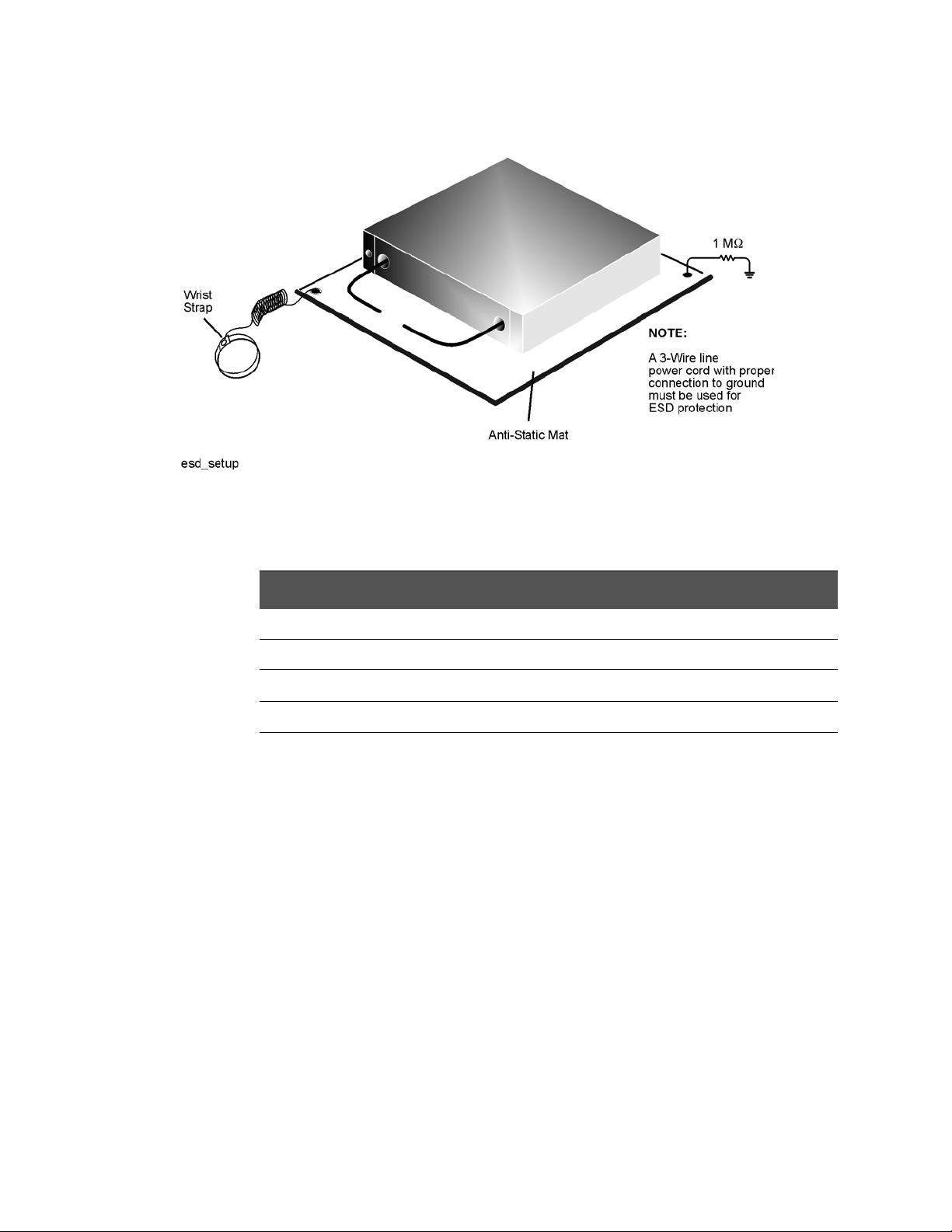
Figure 1-1 shows a typical ESD protection setup using a grounded mat and
wrist strap. Refer to “Electrostatic Discharge Protection” on page 1-6 for part
numbers.
1-6 Keysight Self-Configured System Installation Guide
Safety and Regulatory Information
Electrostatic Discharge Protection
Figure 1-1 ESD Protection Setup
ESD Equipment Required for the Installation
Description Keysight Part Number
ESD grounding wrist strap 9300-1367
5-ft grounding cord for wrist strap 9300-0980
2 x 4 ft conductive table mat and 15-ft grounding wire 9300-0797
ESD heel strap (for use with conductive floors) 9300-1308
Keysight Self-Configured System Installation Guide 1-7
1-
ICES/NMB-001
Safety and Regulatory Information
Regulatory Information
Regulatory Information
This section contains information that is required by various government regulatory agencies.
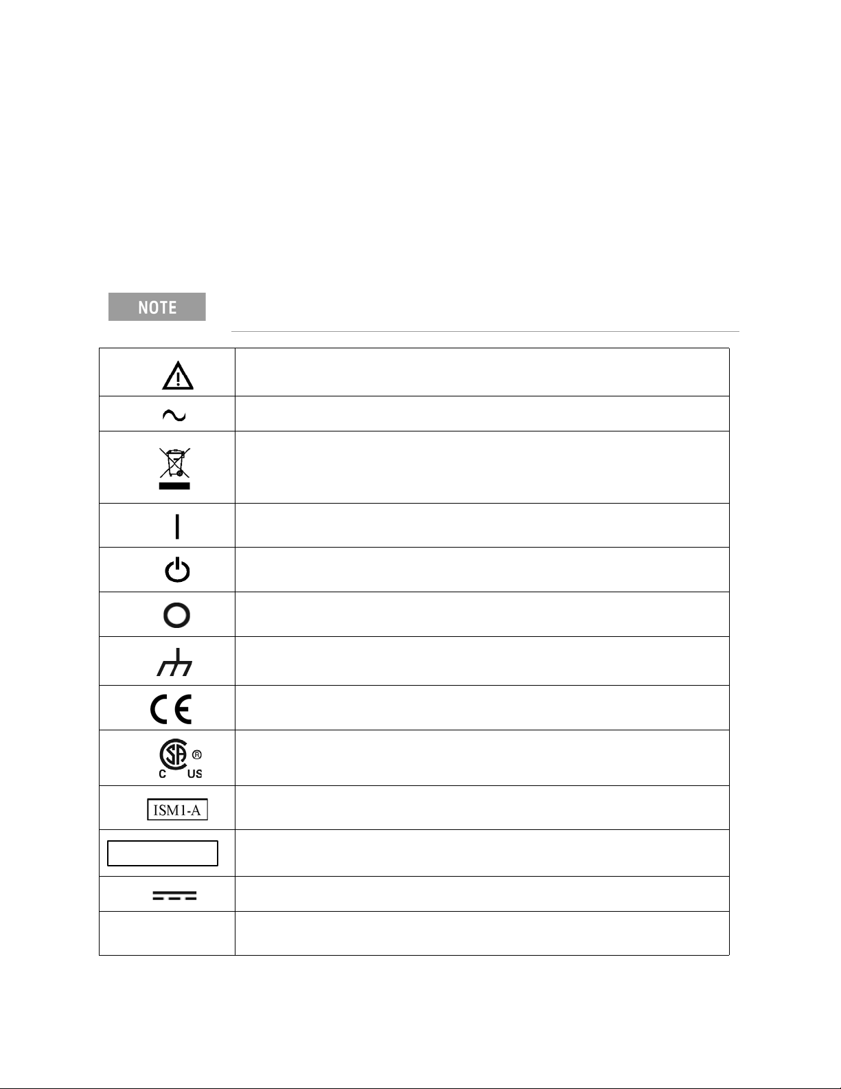
Instrument Markings
Familiarize yourself with these instrument markings and their meanings before operating the instrument.
Some instrument markings may not appear on your analyzer.
The instruction documentation symbol. The product is marked with this symbol when it is necessary for the user to refer to the instructions in the documentation.
The AC symbol indicates the required nature of the line module input power.
This symbol indicates separate collection for electrical and electronic equipment, mandated
under EU law as of August 13, 2005. All electric and electronic equipment are required to be
separated from normal waste for disposal (Reference WEEE Directive, 2002/96/EC).
This symbol indicates that the power line switch is ON.
This symbol indicates that the power line switch is in the STANDBY position.
This symbol indicates that the power line switch is in the OFF position.
This symbol is used to identify a terminal which is internally connected to the product frame or chassis.
The CE mark is a registered trademark of the European Community. (If accompanied by a year, it is when the design was proven.)
The CSA mark is a registered trademark of the CSA International.
This mark designates the product is an Industrial Scientific and Medical Group 1 Class A product (reference CISPR 11, Clause 5).
This is a marking to indicate product compliance with the Canadian Interference-Causing Equipment Standard (ICES-001).
Direct Current.
IP 2 0 The instrument has been designed to meet the requirements of IP 2 0 for egress and
operational environment.
1-8 Keysight Self-Configured System Installation Guide
Safety and Regulatory Information
Regulatory Information
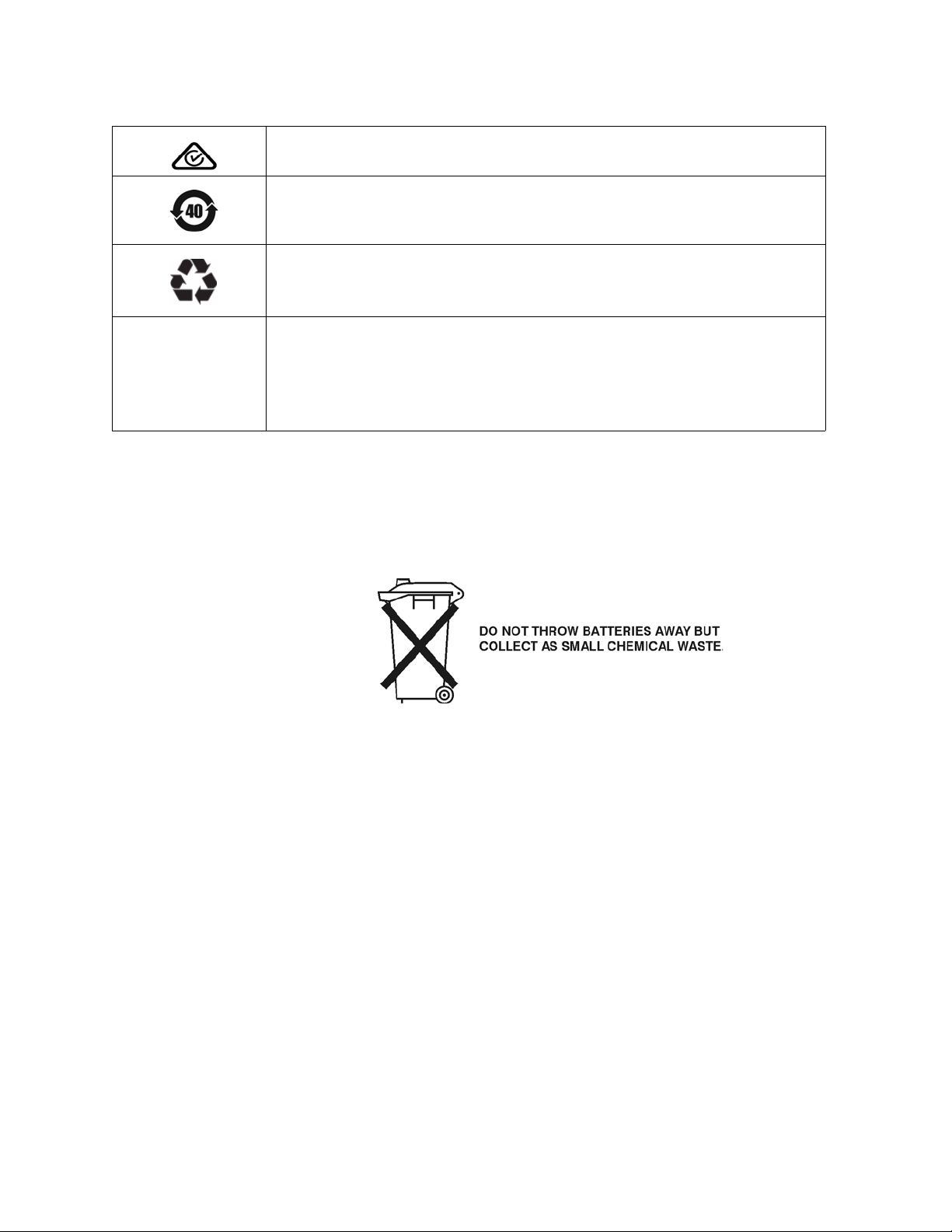
The RCM mark is a registered trademark of the Australian Communications and Media Authority.
Indicates the time period during which no hazardous or toxic substance elements are expected to leak or deteriorate during normal use. Forty years is the expected useful life of the product.
This symbol on all primary or secondary packaging indicates compliance to China standard GB 18455-2001.
South Korean Certification (KC) mark; includes the marking's identifier code which follows the format: MSIP-REM-YYY-ZZZZZZZZZZZZZZ or KCC-REM-YYY-ZZZZZZZZZZZZ.
Lithium Battery Disposal
If the battery on your network analyzer’s CPU board needs to be disposed of, dispose of it in accordance with your country’s requirements. If required, you may return the battery to Keysight Technologies for disposal. Refer to
“Contacting Keysight” on page 5-4 for assistance.
EMC and Safety Information
EMC Information
Complies with European EMC Directive 2014/30/EU
— IEC/EN 61326-1
— CISPR Pub 11 Group 1, Class A
— AS/NZS CISPR 11
— ICES/NMB-001
This ISM device complies with Canadian ICES-001. Cet appareil ISM est conforme a la norme NMB-001 du Canada.
Keysight Self-Configured System Installation Guide 1-9

1-
Safety and Regulatory Information
Regulatory Information
South Korean Class A EMC declaration:
This equipment has been conformity assessed for use in business environments. In a residential environment this equipment may cause radio interference.
— This EMC statement applies to the equipment only for use in
business environment.
Safety:
Complies with the essential requirements of the European Low Voltage Directive as well as current editions of the following standards (dates and editions are cited in the Declaration of Conformity:
— IEC/EN 61010-1
— Canada: CSA C22.2 No. 61010-1
— USA: UL std no. 61010-1
Acoustic Statement: (European Machinery Directive)
Acoustic noise emission
LpA <70 dB
Operator position
Normal operation mode per ISO 7779
To find a current Declaration of Conformity for a specific Keysight product, go to:
http://www.keysight.com/go/conformity
1-10 Keysight Self-Configured System Installation Guide

Safety and Regulatory Information
N5292A Test Set Equipment Ratings
N5292A Test Set Equipment Ratings
Table 1-1 N5292A Equipment Ratings
Nominal voltage and frequency or range 100/120V/220/240 Vac, 50/60 Hz
Power in watts, VA or current 210 W MAX
Keysight Self-Configured System Installation Guide 1-11
1-
Safety and Regulatory Information
Environmental Requirements
Environmental Requirements
Ventilation Requirements: When installing the product in a cabinet, the
convection into and out of the product must not be restricted. The ambient
temperature (outside the cabinet) must be less than the maximum
operating temperature of the instrument by 4 °C for every 100 watts
dissipated in the cabinet. If the total power dissipated in the cabinet is
greater than 800 watts, then forced convection must be used
The environmental requirements shown below are characteristic for the system and are based on the limitations of the PNA network analyzer used.
Table 1-2 Millimeter-wave System Environmental Conditions (Operating)
Environment Tem perat ure
.
Operation
Storage
Measurement Calibration
Performance Verification
Relative Humidity
Pressure Altitude Type tested 0 to 4600 meters (~15,000 feet)
0
°C to 40 °C (41 °F to 104 °F)
–40
°C to +65 °C (–40 °F to 158 °F)
20
°C to 26 °C (68 °F to 79 °F)
Temperature must be within 1
the temperature at which the measurement
calibration was performed.
Type tested at 95%, +40
Table 1-3 N5292/3/5A Environmental Conditions (Operating)
Environment Tem perat ure
for indoor use only (unless specified otherwise.)
Altitude up to 4,600 meters
Temperature 0 to 40 °C
Relative humidity Type tested, 0 to 95% relative humidity,
0
°C to 40 °C
non-condensing up to 40°C
°C (1.8 °F) of
°C (non-condensing)
System Heating and Cooling
Install air conditioning and heating, if necessary, to maintain the ambient temperature within the appropriate range (as given in the table above). Air conditioning capacity must be consistent with the BTU ratings given in Table
1-2 on page 1-12 and Table 1-3 on page 1-12.
1-12 Keysight Self-Configured System Installation Guide

Safety and Regulatory Information
Site Preparation
Required Conditions for Accuracy Enhanced Measurement
Accuracy-enhanced (error-corrected) measurements require the ambient temperature of the millimeter-wave system to be maintained within ± 1 °C of the ambient temperature at calibration.
Site Preparation
Install the instrument so that the detachable power cord is readily identifiable
and is easily reached by the operator. An externally installed switch or circuit
breaker (which is readily identifiable and is easily reached by the operator)
should be used as the disconnecting device.The detachable power cord can
also be used to disconnect the mains circuits from the mains supply before
other parts of the instrument. The front panel switch is only a standby switch
and is not a LINE switch.
Power Requirements
Before installing the system, be sure that the required ac power is available at all necessary locations.
— Three-wire power cables (which provide a safety ground) must be used with
all instruments.
— Air-conditioning equipment (or other motor-operated equipment) should
not be placed on the same ac line that powers the system.
— The table below lists the maximum VA ratings and BTU/hour ratings for all
instruments in the system. This table can be used to determine both the
electrical requirements and the air conditioning requirements of the system.
Keysight Self-Configured System Installation Guide 1-13
1-
Safety and Regulatory Information
Site Preparation
Table 1-4 Power Requirements of the System
Standard Equipment
Instrument Maximum VA Rating Maximum BTU/hour
N522xB and N524xB 350 1195
N5292A millimeter head controller 210 717
OML/VDI millimeter head (x1, x2, x3, or x4)
(Maximum VA rating includes any millimeter heads powered from controller)
(Maximum BTU/hour rating includes any millimeter heads powered from controller)
Tot al 560 1912
Values are verified with 120 Vac supplied to each instrument at 60 Hz.
The N5292A millimeter head controller supplies power to the test head modules.
1-14 Keysight Self-Configured System Installation Guide
Keysight PNA/PNA-X Series
2-Port and 4-Port Self-Configured Microwave Network Analyzer System
Installation Guide
2 System Description
The Low Frequency Extension (LFE) refers to the 900 Hz to 100 MHz
frequency range sold as option 205, 220, 405, and 420 in the N522xB and
option 205, 425, and 429 in the N524xB. All other configuration options are
considered to be "non-LFE". "Broadband" is defined as a system which
can sweep from 900 Hz or 10 MHz to 110/120 GHz.
This document is applicable to non-LFE broadband millimeter-wave
systems and non-LFE and LFE banded millimeter-wave systems. Where
the text applies to both types of systems, "millimeter-wave system" is
used. Where the content is specific to one or the other types of systems,
"non-LFE broadband millimeter-wave system" or "banded
millimeter-wave system" is used.
For N5290/91A LFE broadband millimeter-wave system information refer to
http://literature.cdn.keysight.com/litweb/pdf/N5292-90002.
2-1

2-
System Description
Information in This Chapter
Information in This Chapter
This chapter describes preparing to receiving your 2-port or 4-port self-configured banded or non-LFE broadband millimeter system and the system’s installation procedure(s).
Chapter Two at-a-Glance
Section Title Summary of Content
“Self-Configured Banded or Non-LFE Broadband Millimeter-Wave Network Analyzer System” on page 2-3
“Network Analyzer Requirements” on page 2-8
“N5292A Test Set Description” on page 2-11
“Interconnect Kits, Rackmount Kits, and Optional Parts” on page 2-14
“Compatible Millimeter-wave Modules” on page 2-21
“Basic System Measurement Configurations” on page 2-26
Overview of the banded or non-LFE broadband N52xxB millimeter-wave system.
Description of compatible PNA features.
N5292A test set controller description of front and rear panel features.
Description of the interconnect heads, rackmount kits, and optional parts.
Keysight N5293A/95A millimeter head and OML/VDI millimeter head descriptions of their features.
Millimeter-wave system basic measurement configurations.
2-2 Keysight Self-Configured System Installation Guide
System Description
Self-Configured Banded or Non-LFE Broadband Millimeter-Wave Network Analyzer
System
Self-Configured Banded or Non-LFE Broadband Millimeter-Wave Network Analyzer System
Non-LFE broadband millimeter-wave capability is only available with the
N5293/5A millimeter-wave modules and operates from 10 MHz to
110/120 GHz. For banded systems, the frequency range will vary from
60 GHz to 1.5 THz depending on the OML/VDI millimeter-wave heads
used in the system.
IMPORTANT! Only PNAs and PNA-X network analyzers with a frequency range equal to greater than 20 GHz are compatible with the N5292A test set controller.
IMPORTANT! For additional information on the OML/VDL heads, refer to
“OML/VDI and N5293A/5A Test Heads – Banded Configuration Calibration (Only)” on page 3-21.
Introduction
This section of this document describes system installation and operation for a
banded or non-LFE broadband millimeter-wave system using an N5292A
Millimeter Head Controller. Banded and non-LFE broadband millimeter-wave
systems are made up of three types of major components: a PNA or PNA-X, a
N5292A controller test set, and millimeter-wave heads. These components are
generally purchased separately and assembled by the customer into a system
at the customer's site. This section of the document focuses on receiving the
controller with accessories and then on system installation and operation.
IMPORTANT! For banded systems that are using the OML modules that require DC bias, a separate N5260AK91 power supply and adapter is required. See also, Table 2-9 on page 2-19. And, for VDI modules that require DC bias, use the VDI-175 power supply.
Each OML/VDI module requires a N5290A304 cable adapter to connect to the N5292A test set. See also Table 2-9 on page 2-19.
For additional information on the OML/VDL heads, refer to “OML/VDI and
N5293A/5A Test Heads – Banded Configuration Calibration (Only)” on
page 3-21.
Table 2-3 and Table 2 -4 list compatible PNA and PNA-X models with required
options. Figure 2-10 on page 22 and Figure 2-11 on page 23 list available millimeter-wave modules. Typical system configurations are pictured in Figure
2-1 on page 5, Figure 2-2 on page 5, Figure 2-3 on page 6, and Figure 2-4 on
page 7.
Keysight Self-Configured System Installation Guide 2-3

2-
System Description
Self-Configured Banded or Non-LFE Broadband Millimeter-Wave Network Analyzer
System
The N5292A Millimeter Head Controller is also used as part of the banded and non-LFE broadband analyzer system. Refer to “N5292A Test Set Description”
on page 2-11.
In this document the N5292A will be referred to as the test set.
— The self-configured Non-LFE broadband millimeter-wave system is a 2-port
or 4-port vector network analyzer system 10 MHz to 110 GHz or 10 MHz to
120 GHz.
— The self-configured banded millimeter-wave system is a 2-port or 4-port
vector network analyzer system. The bands are dependent on the type of
OML/VDI heads (60 GHz to 1.5 THz).
The illustration below shows the N52xxB configured for broadband coaxial measurement with Keysight’s N5293/5A millimeter-modules (refer to Figure
2-1 on page 5 and Figure 2-2 on page 5).
The illustrations below shows the third party OML/VDI modules (refer to Figure
2-3 on page 6 and Figure 2-4 on page 7).
2-4 Keysight Self-Configured System Installation Guide
System Description
2-Port N52xxB
PNA Network Analyzer
2-Port N5292A
Millimeter-head
Controller
N5293/5A Millimeter-heads
4-Port N52xxB
PNA Network Analyzer
4-Port N5292A
Millimeter-head
Controller
N5293/5A Millimeter-heads
Self-Configured Banded or Non-LFE Broadband Millimeter-Wave Network Analyzer
System
Figure 2-1 N52xxB 2-Port Non-LFE Broadband Test System – Coaxial Measurement
Configuration (using N5293/5A Millimeter Heads)
Figure 2-2 N52xxB 4-Port Non-LFE Broadband Test System – Coaxial Measurement
Configuration (using N5293/5A Millimeter Heads)
Keysight Self-Configured System Installation Guide 2-5

2-
System Description
Self-Configured Banded or Non-LFE Broadband Millimeter-Wave Network Analyzer
System
Figure 2-3 N52xxB 2-Port Banded Test System – Coaxial Measurement Configuration
(using OML/VDI Millimeter Heads)
2-6 Keysight Self-Configured System Installation Guide

System Description
Self-Configured Banded or Non-LFE Broadband Millimeter-Wave Network Analyzer
System
Figure 2-4 N52xxB 4-Port Banded Test System – Coaxial Measurement Configuration
(using OML/VDI Millimeter Heads)
Keysight Self-Configured System Installation Guide 2-7

2-
System Description
Network Analyzer Requirements
Network Analyzer Requirements
The required options for PNA models are indicated in the “PNA Option(s)” column of Table 2-3 on page 2-10. The required options for PNA-X models are indicated in the “PNA Option(s)” column of Table 2-4 on page 2-10.
The minimum firmware revision for PNA and PNA-X models is ≥A.12.80.
Space Requirements
Standard installation of the N52xxB with N5292A test set millimeter-wave system includes configuration and installation of the system on a customer provided lab bench or table top of adequate size and strength.
N52xxB with N5292A Test Set System Weight and Dimensions
Table 2-1 Stacked System Benchtop Dimensions
Model
2-Port 48 kg to 64 kg 37.5 cm (8U) 48.3 cm 57.8 cm or 65 cm
4-Port 51 kg to 70 kg
1. System benchtop dimensions are dependent on the number of ports, PNA model, and the style of the millimeter-head.
2. Minimum weights calculated with one VDI millimeter-head. Maximum weights calculated with four OML
millimeter-heads.
3. All heights include the height of a single set of instrument feet (1.3 cm).
Weight
2
Required Benchtop Dimensions for the System
3
Height
1
Width Depth
Component Weight and Dimensions
Table 2-1, “Stacked System Benchtop Dimensions,” shows the maximum
weight and dimensions of the N52xxB with N5292A test set millimeter-wave
system components. Refer also to Table 2-2 on page 2-9 for test head module
dimensions.
2-8 Keysight Self-Configured System Installation Guide

System Description
Network Analyzer Requirements
Table 2-2 N52xxB Banded and Non-LFE Broadband Millimeter-wave System
Components Weights and Dimensions
Model Weight
N5221B, N5222B, N5241B, N5242B, N5249B
36 kg to 37 kg,
depending on
Height
1
Width Depth
28.6 cm (6U) 48.3 cm 57.8 cm
hardware options
N5224B, N5225B, N5244B, N5245B
36 kg to 45 kg,
depending on
65 cm
hardware options
N5227B, N5247B 41 kg to 49 kg,
depending on
hardware options
N5292A 9 kg 10.2 cm (2U) 42.6 cm 60 cm
N5293/5A Millimeter-wave test
1.6 kg 9 cm 7.3 cm 16.7 cm
head modules
OML Millimeter-wave test head modules
VDI Millimeter-wave test head modules
1.3 kg to 3 kg
1 kg (Rx) to
1.8 kg (TxRx & TxRef)
6.9 cm (S & T/R)
6.9 cm (T)
3.8 cm (Rx)
3.8 cm (TxRx &
TxRef )
10.9 cm (S & T/R)
10.9 cm (T)
7.6 cm (Rx)
7.6 cm (TxRx &
TxRef )
33 cm (S & T/R)
11.9 cm (T)
8.9 cm (Rx)
21.6 cm (TxRx &
TxRef )
1. All heights include the height of a single set of instrument feet (1.3 cm).
Keysight Self-Configured System Installation Guide 2-9

2-
System Description
System Configurations
System Configurations
Table 2-3 and Table 2-4 on page 2-10 document all supported module
configurations for S-Parameter measurement capabilities for broadband and
banded mm-wave systems using the N5292A Option 200 and N5292A Option
400 test set. See also, Table 2-10 on page 2-22 through Table 2-11 on
page 2-23.
Table 2-3 PNA Based Configurations
PNA Model (s)
N5222B 201, 217, or 219 N5292A-200 N5292A-222
N5224B/5B/7B 201, 217, or 219 N5292A-200 N5292A-224
1. All PNA’s require Option 020.
PNA Options
401, 417, or 419 N5292A-200 N5292A-222
401, 417, or 419 N5292A-200 N5292A-224
1
Test Set Cable Interface
Kit
N5292A-222
N5292A-400 N5292A-442
N5292A-400 N5292A-444
Table 2-4 PNA-X Based Configurations
PNA-X Model (s) PNA
1
Option(s)
N5242B 201, 217, 219, 222, or 224 N5292A-200 N5292A-222
401, 417, 419, 422, or 423 N5292A-200 N5292A-222
Test Set Cable Interface
Kit
N5292A-400 N5292A-442
N5244/5B/47B 201, 217, 219, 222, or 224 N5292A-200 N5292A-224
401, 417, 419, 422, or 423 N5292A-200 N5292A-224
N5292A-400 N5292A-444
1. All PNA-X’s require Option 020.
2-10 Keysight Self-Configured System Installation Guide
 Loading...