

Page 1

Getting
Started Guide
Keysight
N5166B CXG
N5171B/72B/73B EXG
N5181B/82B/83B MXG
X-Series Signal Generators
Page 2
Notices
© Keysight Technologies, Inc.
2012-2021
No part of this manual may be
reproduced in any form or by any
means (including electronic storage
and retrieval or translation into a
foreign language) without prior
agreement and written consent from
Keysight Technologies, Inc. as
governed by United States and
international copyright laws.
Trademark Acknowledgments
Manual Part Number
N5180-90054
Edition
Edition 1, January 2021
Supersedes: September 2019
Printed in USA/Malaysia
Published by:
Keysight Technologies
1400 Fountaingrove Parkway
Santa Rosa, CA 95403
Warranty
THE MATERIAL CONTAINED IN THIS
DOCUMENT IS PROVIDED “AS IS,”
AND IS SUBJECT TO BEING
CHANGED, WITHOUT NOTICE, IN
FUTURE EDITIONS. FURTHER, TO
THE MAXIMUM EXTENT PERMITTED
BY APPLICABLE LAW, KEYSIGHT
DISCLAIMS ALL WARRANTIES,
EITHER EXPRESS OR IMPLIED WITH
REGARD TO THIS MANUAL AND
ANY INFORMATION CONTAINED
HEREIN, INCLUDING BUT NOT
LIMITED TO THE IMPLIED
WARRANTIES OF
MERCHANTABILITY AND FITNESS
FOR A PARTICULAR PURPOSE.
KEYSIGHT SHALL NOT BE LIABLE
FOR ERRORS OR FOR INCIDENTAL
OR CONSEQUENTIAL DAMAGES IN
CONNECTION WITH THE
FURNISHING, USE, OR
PERFORMANCE OF THIS
DOCUMENT OR ANY INFORMATION
CONTAINED HEREIN. SHOULD
KEYSIGHT AND THE USER HAVE A
SEPARATE WRITTEN AGREEMENT
WITH WARRANTY TERMS
COVERING THE MATERIAL IN THIS
DOCUMENT THAT CONFLICT WITH
THESE TERMS, THE WARRANTY
TERMS IN THE SEPARATE
AGREEMENT WILL CONTROL.
Technology Licenses
The hardware and/or software
described in this document are
furnished under a license and may be
used or copied only in accordance
with the terms of such license.
U.S. Government Rights
The Software is “commercial
computer software,” as defined
by Federal Acquisition Regulation
(“FAR”) 2.101. Pursuant to FAR
12.212 and 27.405-3 and
Department of Defense FAR
Supplement (“DFARS”) 227.7202,
the U.S. government acquires
commercial computer software
under the same terms by which
the software is customarily
provided to the public.
Accordingly, Keysight provides
the Software to U.S. government
customers under its standard
commercial license, which is
embodied in its End User License
Agreement (EULA), a copy of
which can be found at
http://www.keysight.com/find/sweula
The license set forth in the EULA
represents the exclusive authority
by which the U.S. government
may use, modify, distribute, or
disclose the Software. The EULA
and the license set forth therein,
does not require or permit,
among other things, that
Keysight: (1) Furnish technical
information related to
commercial computer software
or commercial computer
software documentation that is
not customarily provided to the
public; or (2) Relinquish to, or
otherwise provide, the
government rights in excess of
these rights customarily provided
to the public to use, modify,
reproduce, release, perform,
display, or disclose commercial
computer software or
commercial computer software
documentation. No additional
government requirements
beyond those set forth in the
EULA shall apply, except to the
extent that those terms, rights, or
licenses are explicitly required
from all providers of commercial
computer software pursuant to
the FAR and the DFARS and are
set forth specifically in writing
elsewhere in the EULA. Keysight
shall be under no obligation to
update, revise or otherwise
modify the Software. With
respect to any technical data as
defined by FAR 2.101, pursuant
to FAR 12.211 and 27.404.2 and
DFARS 227.7102, the U.S.
government acquires no greater
than Limited Rights as defined in
FAR 27.401 or DFAR 227.7103-5
(c), as applicable in any technical
data.
Safety Notices
A CAUTION notice denotes a hazard. It
calls attention to an operating
procedure, practice, or the like that,
if not correctly performed or adhered
to, could result in damage to the
product or loss of important data. Do
not proceed beyond a CAUTION
notice until the indicated conditions
are fully understood and met.
A WARNING notice denotes a hazard.
It calls attention to an operating
procedure, practice, or the like that,
if not correctly performed or adhered
to, could result in personal injury or
death. Do not proceed beyond a
WARNING notice until the indicated
conditions are fully understood and
met.
Page 3

Where to Find the Latest Information
Documentation is updated periodically. For the latest information about these products, including instrument software
upgrades, application information, and product information, browse to one of the following URLs, according to the name
of your product:
http://www.keysight.com/find/mxg
To receive the latest updates by email, subscribe to Keysight Email Updates at the following URL:
http://www.keysight.com/find/MyKeysight
Information on preventing instrument damage can be found at:
www.keysight.com/find/PreventingInstrumentRepair
Is your product software up-to-date?
Periodically, Keysight releases software updates to fix known defects and incorporate product enhancements. To search
for software updates for your product, go to the Keysight Technical Support website at:
http://www.keysight.com/find/techsupport
3
Page 4

4
Page 5

Table of Contents
1. Safety Information
Warnings, Cautions, and Notes . . . . . . . . . . . . . . . . . . . . . . . . . . . . . . . . . . . . . . . . . . . . . . . . . . . . . . . . . . . . . . . . . . 9
General Safety Considerations . . . . . . . . . . . . . . . . . . . . . . . . . . . . . . . . . . . . . . . . . . . . . . . . . . . . . . . . . . . . . . . . . . 10
Instrument Markings. . . . . . . . . . . . . . . . . . . . . . . . . . . . . . . . . . . . . . . . . . . . . . . . . . . . . . . . . . . . . . . . . . . . . . . . . . 11
2. Getting Started
Checking the Shipment . . . . . . . . . . . . . . . . . . . . . . . . . . . . . . . . . . . . . . . . . . . . . . . . . . . . . . . . . . . . . . . . . . . . . . . 14
Verifying Pre-Installed Software License . . . . . . . . . . . . . . . . . . . . . . . . . . . . . . . . . . . . . . . . . . . . . . . . . . . . . . . . . . 15
Signal Generator Physical Characteristics . . . . . . . . . . . . . . . . . . . . . . . . . . . . . . . . . . . . . . . . . . . . . . . . . . . . . . . . . 16
Dimensions . . . . . . . . . . . . . . . . . . . . . . . . . . . . . . . . . . . . . . . . . . . . . . . . . . . . . . . . . . . . . . . . . . . . . . . . . . . . . 16
Weight . . . . . . . . . . . . . . . . . . . . . . . . . . . . . . . . . . . . . . . . . . . . . . . . . . . . . . . . . . . . . . . . . . . . . . . . . . . . . . . . . 16
Meeting Environmental and Electrical Requirements . . . . . . . . . . . . . . . . . . . . . . . . . . . . . . . . . . . . . . . . . . . . . . . . 17
Environment. . . . . . . . . . . . . . . . . . . . . . . . . . . . . . . . . . . . . . . . . . . . . . . . . . . . . . . . . . . . . . . . . . . . . . . . . . . . . 17
Ventilation . . . . . . . . . . . . . . . . . . . . . . . . . . . . . . . . . . . . . . . . . . . . . . . . . . . . . . . . . . . . . . . . . . . . . . . . . . . . . . 18
Line Setting Requirements . . . . . . . . . . . . . . . . . . . . . . . . . . . . . . . . . . . . . . . . . . . . . . . . . . . . . . . . . . . . . . . . . 18
Connecting the AC Power Cord . . . . . . . . . . . . . . . . . . . . . . . . . . . . . . . . . . . . . . . . . . . . . . . . . . . . . . . . . . . . . 19
Configuring the Display . . . . . . . . . . . . . . . . . . . . . . . . . . . . . . . . . . . . . . . . . . . . . . . . . . . . . . . . . . . . . . . . . . . . . . . 20
Configuring for Remote Control . . . . . . . . . . . . . . . . . . . . . . . . . . . . . . . . . . . . . . . . . . . . . . . . . . . . . . . . . . . . . . . . . 21
LAN Configuration. . . . . . . . . . . . . . . . . . . . . . . . . . . . . . . . . . . . . . . . . . . . . . . . . . . . . . . . . . . . . . . . . . . . . . . . 21
GPIB Configuration . . . . . . . . . . . . . . . . . . . . . . . . . . . . . . . . . . . . . . . . . . . . . . . . . . . . . . . . . . . . . . . . . . . . . . . 22
Ordering Accessories . . . . . . . . . . . . . . . . . . . . . . . . . . . . . . . . . . . . . . . . . . . . . . . . . . . . . . . . . . . . . . . . . . . . . . . . . 23
Proper Use and Cleaning . . . . . . . . . . . . . . . . . . . . . . . . . . . . . . . . . . . . . . . . . . . . . . . . . . . . . . . . . . . . . . . . . . . . . . 25
Cleaning Suggestions . . . . . . . . . . . . . . . . . . . . . . . . . . . . . . . . . . . . . . . . . . . . . . . . . . . . . . . . . . . . . . . . . . . . . 25
Returning a Signal Generator to Keysight Technologies . . . . . . . . . . . . . . . . . . . . . . . . . . . . . . . . . . . . . . . . . . . . . . 25
Contacting Keysight . . . . . . . . . . . . . . . . . . . . . . . . . . . . . . . . . . . . . . . . . . . . . . . . . . . . . . . . . . . . . . . . . . . . . . . . . . 26
3. Operation Verification
Running Self Test . . . . . . . . . . . . . . . . . . . . . . . . . . . . . . . . . . . . . . . . . . . . . . . . . . . . . . . . . . . . . . . . . . . . . . . . . . . . 28
Self Test Failure . . . . . . . . . . . . . . . . . . . . . . . . . . . . . . . . . . . . . . . . . . . . . . . . . . . . . . . . . . . . . . . . . . . . . . . . . . 29
Frequency Range and Accuracy Check . . . . . . . . . . . . . . . . . . . . . . . . . . . . . . . . . . . . . . . . . . . . . . . . . . . . . . . . . . . 30
Frequency Counter Procedure . . . . . . . . . . . . . . . . . . . . . . . . . . . . . . . . . . . . . . . . . . . . . . . . . . . . . . . . . . . . . . 30
Troubleshooting Problems with the Frequency Accuracy Check . . . . . . . . . . . . . . . . . . . . . . . . . . . . . . . . . . . .32
Checking the Output Power . . . . . . . . . . . . . . . . . . . . . . . . . . . . . . . . . . . . . . . . . . . . . . . . . . . . . . . . . . . . . . . . . . . . 32
N5171B/81B Test Procedure. . . . . . . . . . . . . . . . . . . . . . . . . . . . . . . . . . . . . . . . . . . . . . . . . . . . . . . . . . . . . . . . 33
N5171B/81B Alternative Test Procedure . . . . . . . . . . . . . . . . . . . . . . . . . . . . . . . . . . . . . . . . . . . . . . . . . . . . . . 34
N5166B/72B/82B Test Procedure. . . . . . . . . . . . . . . . . . . . . . . . . . . . . . . . . . . . . . . . . . . . . . . . . . . . . . . . . . . . 36
N5166B/72B/82B Alternative Test Procedure . . . . . . . . . . . . . . . . . . . . . . . . . . . . . . . . . . . . . . . . . . . . . . . . . . 39
N5173B/83B Test Procedure. . . . . . . . . . . . . . . . . . . . . . . . . . . . . . . . . . . . . . . . . . . . . . . . . . . . . . . . . . . . . . . . 40
N5173B/83B Alternative Test Procedure . . . . . . . . . . . . . . . . . . . . . . . . . . . . . . . . . . . . . . . . . . . . . . . . . . . . . . 41
Troubleshooting Problems with the Output Power Check . . . . . . . . . . . . . . . . . . . . . . . . . . . . . . . . . . . . . . . . . 43
4. Regulatory Information
General . . . . . . . . . . . . . . . . . . . . . . . . . . . . . . . . . . . . . . . . . . . . . . . . . . . . . . . . . . . . . . . . . . . . . . . . . . . . . . . . . . . . 46
5
Page 6

Certification. . . . . . . . . . . . . . . . . . . . . . . . . . . . . . . . . . . . . . . . . . . . . . . . . . . . . . . . . . . . . . . . . . . . . . . . . . . . . . . . . 46
Assistance . . . . . . . . . . . . . . . . . . . . . . . . . . . . . . . . . . . . . . . . . . . . . . . . . . . . . . . . . . . . . . . . . . . . . . . . . . . . . . . . . . 46
Statement of Compliance. . . . . . . . . . . . . . . . . . . . . . . . . . . . . . . . . . . . . . . . . . . . . . . . . . . . . . . . . . . . . . . . . . . . . . 46
Compliance with Canadian EMC Requirements . . . . . . . . . . . . . . . . . . . . . . . . . . . . . . . . . . . . . . . . . . . . . . . . . . . . 46
South Korean Class A EMC Declaration. . . . . . . . . . . . . . . . . . . . . . . . . . . . . . . . . . . . . . . . . . . . . . . . . . . . . . . . . . . 47
Compliance with European Machinery Directive Acoustic Requirement . . . . . . . . . . . . . . . . . . . . . . . . . . . . . . . . . 47
5. Open Source Licenses
Apple mDNSresponder. . . . . . . . . . . . . . . . . . . . . . . . . . . . . . . . . . . . . . . . . . . . . . . . . . . . . . . . . . . . . . . . . . . . . . . . 50
Sun ONC/RPC. . . . . . . . . . . . . . . . . . . . . . . . . . . . . . . . . . . . . . . . . . . . . . . . . . . . . . . . . . . . . . . . . . . . . . . . . . . . . . . 56
WCELIBCEX - Windows CE C Library Extensions . . . . . . . . . . . . . . . . . . . . . . . . . . . . . . . . . . . . . . . . . . . . . . . . . . . 57
6
Page 7

Documentation Overview
Getting Started Guide
User’s Guide
— Safety Information
— Receiving the Instrument
— Environmental & Electrical Requirements
—Basic Setup
— Accessories
— Operation Verification
— Regulatory Information
— Signal Generator Overview
— Preferences & Enabling Options
— Basic Operation
—Optimize Performance
— Avionics VOR/ILS (Option N5180302B)
— Analog Modulation (Option UNT)
— Pulse Modulation (
Options UNW or N5180320B)
— Basic Digital Operation—No BBG Option
— Basic Digital Operation (
Options 653/655/656/657)
— Digital Signal Interface Module (Option 003 /004)
— Baseband Operating Mode—Primary, BERT, or N5102A
— BERT (Option N5180UN7B)
— Real–Time Noise—AWGN (Option N5180403B)
— Real–Time Phase Noise Impairments (Option N5180432B)
— Real–Time Fading (Option 660)
— Custom Digital Modulation (
Option N5180431B)
— Multitone and Two-Tone Waveforms (Option N5180430B)
— Troubleshooting
— Working in a Secure Environment
Programming Guide
SCPI Reference
— Getting Started with Remote Operation
— Using IO Interfaces
— Programming Examples
— Programming the Status Register System
— Creating and Downloading Files
— Creating and Downloading User–Data Files
— SCPI Basics
— Basic Function Commands
— System Commands
— Analog Modulation Commands
— Arb Commands
— Avionics VOR/ILS Commands
— Bit Error Rate Test (BERT) Commands
— Digital Signal Interface Module Commands
— Real-Time Commands
7
Page 8

Programming
Compatibility Guide
— Provides a listing of SCPI commands and programming codes for
signal generator models that are supported by the Keysight CXG,
EXG, and MXG X- Series signal generators.
Service Guide
— Troubleshooting
— Replaceable Parts
— Assembly Replacement
— Post–Repair Procedures
— Safety and Regulatory Information
— Instrument History
Error Messages Guide
— Error Messages
— Error Message Format
— Error Message Type
— List of Error Messages
Key Help
a
— Key function description
— Related SCPI commands
a. Press the Help key, and then the key for which you wish help.
8
Page 9

Keysight Technologies
X-Series Signal Generators
Getting Started Guide
1 Safety Information
— Warnings, Cautions, and Notes on page 9
— General Safety Considerations on page 10
— Instrument Markings on page 11
Warnings, Cautions, and Notes
The documentation for this product uses the following safety notations.
Familiarize yourself with each notation and its meaning before operating the
signal generator.
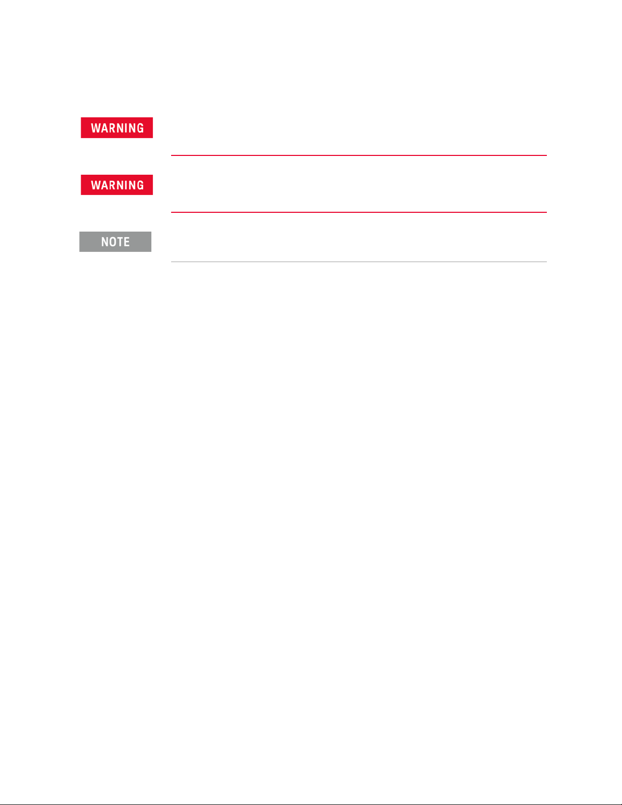
Warning denotes a hazard. It calls attention to a condition or situation that could
result in personal injury or loss of life. Do not proceed beyond a warning until you
fully understand the indicated conditions or situations.
Caution calls attention to a condition or situation that could result in damage to
or destruction of the signal generator, or in the loss of a user’s settings or data. Do
not proceed beyond a caution until you fully understand the indicated conditions.
Note calls the user’s attention to an important point or special information in the
text.
9
Page 10
Safety Information
General Safety Considerations
General Safety Considerations
If the signal generator is not used as specified, the protection provided by the
equipment could be impaired. The signal generator must be used in a normal
condition only, in which all means for protection are intact.
Personal injury may result if the signal generator covers are removed. There are no
operator serviceable parts inside. To avoid electrical shock, refer servicing to
qualified personnel.
Safety of any system incorporating the equipment is the responsibility of the
assembler of the system.
10 Keysight CXG, EXG, and MXG X-Series Signal Generators Getting Started Guide
Page 11
Safety Information
Instrument Markings
Instrument Markings
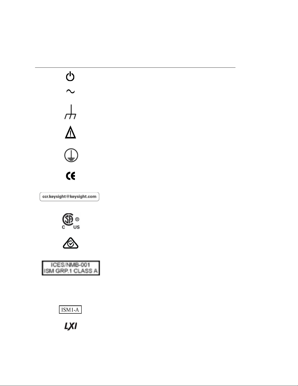
The signal generator may have the following markings. Familiarize yourself
with each marking and its meaning before operating the signal generator.
This symbol marks the standby position of the power line switch.
This symbol indicates that the input power required is AC.
This symbol indicates Frame or chassis Terminal.
The instruction documentation symbol. The product is marked with this
symbol when it is necessary for you to refer to instructions in the
documentation.
This symbol identifies the Protective Conductor Terminal.
The CE mark is a registered trademark of the European Community. If this
symbol is accompanied by a year, it is the year when the design was proven.
It indicates that the product complies with all relevant directives.
The Keysight email address is required by EU directives applicable to our
product.
The CSA mark is a registered trademark of the CSA International.
The RCM mark is a registered trademark of the Australian Communications
and Media Authority.
This is a combined marking to indicate product compliance with industry
Canadian Interference-Causing Equipment Standard (ICES-001).
This is also a symbol of an Industrial Scientific and Medical Group 1 Class A
product (CISPR 11, Clause 5).
ICES/NMB-001 This is a marking to indicate product compliance with the Industry Canadian
Interference-Causing Equipment Standard (ICES-001), Cet appareil ISM est
conforme a la norme NMB du Canada.
This is the symbol of an Industrial Scientific and Medical Group 1 Class A
Product. (CISPER 11, Clause 5)
This symbol indicates conformance to the standard specifications.
Keysight CXG, EXG, and MXG X-Series Signal Generators Getting Started Guide 11
Page 12
Safety Information
Instrument Markings
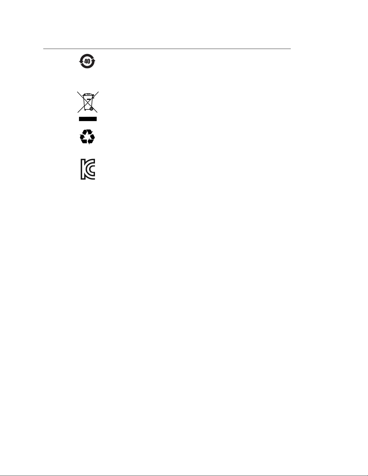
China Restricted Substance Product Label. The EPUP (environmental
protection use period) number in the center Indicates the time period during
which no hazardous or toxic substance elements are expected to leak or
deteriorate during normal use. Forty years is the expected useful life of the
product.
This WEEE symbol indicates separate collection for electrical and electronic
equipment, mandated under EU law as of August 13, 2005. All electric and
electronic equipment are required to be separated from normal waste for
disposal (Reference WEEE Directive, 2002/96/EC).
Universal recycling symbol. This symbol indicates compliance with the China
standard GB 18455-2001 as required by the China RoHS regulations for
paper/fiberboard packaging.
South Korean Certification (KC) mark. It includes the marking’s identifier
code which follows this format: R-R-Kst-ZZZZZZZZZ
To view the EMC Declaration, see “South Korean Class A EMC
Declaration” on page 47
.
12 Keysight CXG, EXG, and MXG X-Series Signal Generators Getting Started Guide
Page 13
Keysight Technologies
X-Series Signal Generators
Getting Started Guide
2 Getting Started
To avoid damaging or degrading the performance of the signal generator, do not
exceed 27 dBm (0.5W) for N5173B/83B models, or 33 dBm (2W) for
N5166B/N5171B/72B/81B/82B models, or maximum of reverse power levels at
the RF input. See also Tips for Preventing Signal Generator Damage on
www.keysight.com.
Software Updates
Is your product software up-to-date? Periodically, Keysight releases software
updates to fix known defects and incorporate product enhancements. To search
for software updates for your product, go to the Keysight Technical Support
website at
www.keysight.com/find/ss_firmware.
Documentation Updates
Is your product documentation up-to-date? To search for documentation updates
for your product, go to the Keysight X-Series Signal Generators website at
www.keysight.com/find/X-Series_SG.
— Checking the Shipment on page 14
— Verifying Pre-Installed Software License on page 15
— Signal Generator Physical Characteristics on page 16
— Meeting Environmental and Electrical Requirements on page 17
— Configuring the Display on page 20
— Configuring for Remote Control on page 21
— Ordering Accessories on page 23
— Proper Use and Cleaning on page 25
— Returning a Signal Generator to Keysight Technologies on page 25
— Contacting Keysight on page 26
13
Page 14

Getting Started
Checking the Shipment
Checking the Shipment
1. Inspect the shipping container for damage.
Signs of damage can include a dented or torn shipping container or
cushioning material that indicates signs of unusual stress or compacting.
2. Carefully remove the contents from the shipping container and verify that
your order is complete.
The following items are included with each signal generator:
— Getting Started Guide
— three-prong AC power cord specific to geographic location
3. Verify that the options/accessories you ordered are included with the
shipment by checking the serial number label on the rear of the signal
generator and the packing literature included with the shipment.
See also, “Ordering Accessories” on page 23.
4. If a pre-installed software license is part of the instrument order, verify its
installation using the directions outlined in “Verifying Pre-Installed
Software License” on page 15.
14 Keysight CXG, EXG, and MXG X-Series Signal Generators Getting Started Guide
Page 15

Getting Started
Verifying Pre-Installed Software License
Veri f ying Pre-I nstalled Software License
If you purchased a signal generator where the order included the
pre-installation of a fixed perpetual Signal Studio license (N76xx), or a Test
Management Environment (TME) software license (N78xxA), or both, verify the
license installation using the following key path:
Utility > Instrument Info > Options Info
This opens a menu with the choices: Instrument Options, Auxiliary
Software Options, and Waveform Licenses. To view the license, press the
appropriate menu key:
— For a Signal Studio license, press Instrument Options.
— For the TME license, press Auxiliary Software Options.
If a license is pre-installed, the software for that license still needs to be
downloaded onto your PC. Use the following links to access the software for
download and installation:
— Signal Studio software: www.keysight.com/find/signalstudio
—TME software: www.keysight.com/find/calibrationsoftware
If the software license(s) was ordered with the instrument for pre-installation
and it does not show in the instrument, please contact Keysight Technologies:
www.keysight.com/find/contactus
Keysight CXG, EXG, and MXG X-Series Signal Generators Getting Started Guide 15
Page 16

Getting Started
Signal Generator Physical Characteristics
Signal Generator Physical Characteristics
Dimensions
88 mm H x 426 mm W x 489 mm L (length includes rear panel feet)
(3.5 in H x 16.8 in W x 19.2 in L)
Max length (L) including RF connector tip to end of rear panel feet
is 508 mm (20 in)
We i g h t
N5171B/81B: 13.6 kg (30 lb)
N5166B/72B/82B: 15.9 kg (35 lb)
N5173B/83B: 14.5–15 kg (32–33 lb)
16 Keysight CXG, EXG, and MXG X-Series Signal Generators Getting Started Guide
Page 17
Getting Started
Meeting Environmental and Electrical Requirements
Meeting Environmental and Electrical Requirements
To avoid the loss of data, GPIB settings, or current user instrument states that
have not been permanently saved to non-volatile memory, the signal generator
should always be powered down either via the signal generator's front panel
power button or the appropriate SCPI command. Signal generator's installed in
rack systems and powered down with the system rack power switch rather than
the signal generator's front panel switch display a Error -310 due to the signal
generator not being powered down correctly.
The input terminals for this product are classified as Measurement Category
None.
Environment
— For indoor use only.
—altitudes
Only with Option 660:
—0 to 55°C temperature, unless otherwise specified
—Maximum Relative Humidity (non-condensing): 95%RH up to 40°C,
decreases linearly to 45%RH at 55°C
— Storage: –40 to 70°C
≤ 15,092 feet (4,600 meters)
≤ 9,843 feet (3,000 meters)
1
This product is designed for use in INSTALLATION CATEGORY II and POLLUTION
DEGREE 2, per IEC 61010-1 Third Edition.
1. From 40°C to 55°C, the maximum % Relative Humidity follows the line of constant
dew point.
Keysight CXG, EXG, and MXG X-Series Signal Generators Getting Started Guide 17
Page 18
Ventilation
Getting Started
Meeting Environmental and Electrical Requirements
The instruments can operate with mains supply voltage fluctuations up to ± 10%
of the nominal voltage.
Ventilation holes are located on the rear panel and all four sides of the signal
generator cover. To ensure proper air flow through the signal generator, do not
allow these holes to be obstructed.
Rack-mounted units
When installing the instrument(s) into a cabinet, consideration shall be given
to the convection flow into and out of the cabinet. Consideration shall also be
given to the individual instruments to avoid having the heated discharge of one
instrument, now becoming the cooling intake air for another instrument.
Another area of concern is verification that the maximum ambient operating
temperature of the instrument(s) is not exceeded by cabinet installation.
Keysight recommends forced air convection whenever an instrument(s) are
installed in a cabinet and further recommends that the maximum operating
temperature of the cabinet be reduced 10°C from the lowest, of the maximum
operating temperature of a single instrument.
If there are any concerns or special requirements a Keysight Field Engineer
should be consulted to assure instrument(s) temperature compliance and
performance.
Line Setting Requirements
The signal generator has autoranging line voltage input; ensure that the supply
voltage is within the specified range.
Voltage: 100/120 volts nominal
Frequency: for 100/120 volts: 50/60/400 Hz nominal
Power: 160 W maximum (N5171B & N5181B)
220/240 volts nominal
for 220/240 volts: 50/60 Hz nominal
300 W maximum (N5166B, N5172B & N5182B)
280 W maximum (N5173B & N5183B)
18 Keysight CXG, EXG, and MXG X-Series Signal Generators Getting Started Guide
Page 19

Getting Started
Meeting Environmental and Electrical Requirements
Connecting the AC Power Cord
This is a Safety Class 1 Product provided with a protective earth ground
incorporated into the power cord. The front panel switch is only a standby
switch; it is not a line switch. The AC power cord is the disconnecting device
that disconnects the signal generator mains circuits from the mains supply.
Alternatively, an external switch or circuit breaker, readily identifiable and
easily reached by the operator, may be used as a disconnecting device.
The instrument shall be set flat in its normal use position so that the detachable
power cord is readily identifiable and is easily reached by the operator. It shall not
be placed on the four feet of the rear panel in normal use.
The mains plug shall be inserted only in a socket outlet provided with a protective
earth contact. Always use the three-prong AC power cord supplied with the signal
generator. Personal injury can occur if there is any interruption of the protective
conductor inside or outside of the signal generator. Intentional interruption is
prohibited.
The mains wiring and connectors shall be compatible with the connector used in
the premise electrical system. Inadequate earth grounding can damage the signal
generator. Always use the three-prong AC power cord supplied with the signal
generator.
To avoid possible instrument damage, use the Keysight supplied power cord or
one with same or better electrical rating.
Connect the AC power cord as follows:
1. Ensure that the power cord is not damaged.
2. Install the signal generator so that one of the following items is readily
identifiable and easily reached by the operator: AC power cord, alternative
switch, or circuit breaker.
3. Insert the mains plug into a socket outlet provided with a protective earth
grounding.
Keysight CXG, EXG, and MXG X-Series Signal Generators Getting Started Guide 19
Page 20
Getting Started
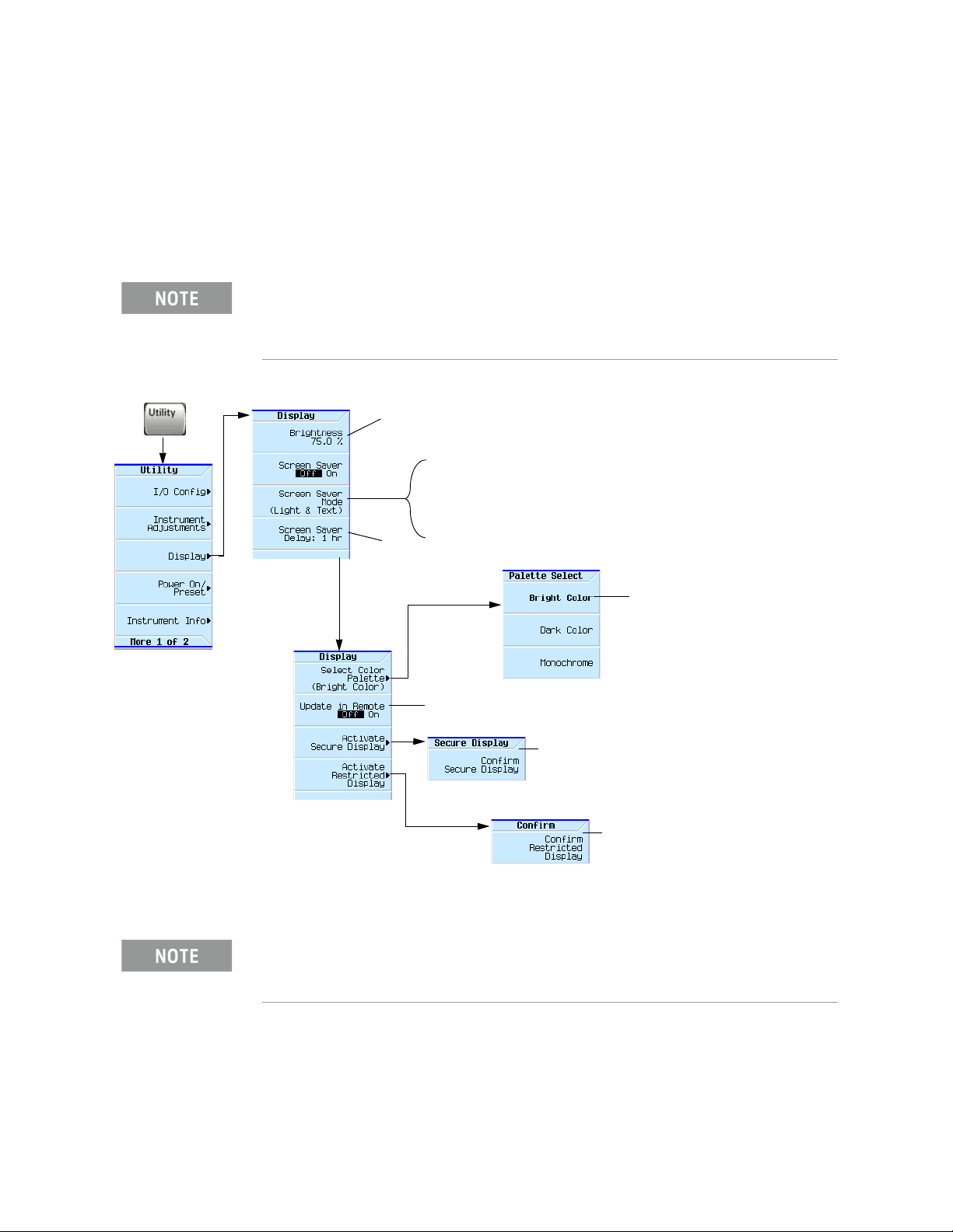
For details on a key, press Help and then the desired key.
Range: 0—100
Range: 1—12 hours, in 1 hour increments
Light Only turns the display light off, leaving the text visible at a low intensity.
Light & Text turns the display light and the text off.
If the display remains unchanged for long periods of time, use this mode to prevent the
text from burning the display.
When on, commands executed through the remote control bus
update the signal generator display accordingly.
The display blanks, except for the message
Secure Display Activated, and the front panel keys
are disabled. Cycle the instrument power to exit
secure display mode.
For information on using the secure display, refer to
the User’s Guide.
Dark text on a light background.
Instrument frequency information is hidden
and front panel frequency control is
disabled. Preset the instrument or cycle
the power to re-enable the front panel.
For information on using the restricted
display, refer to the User’s Guide.
Configuring the Display
Configuring the Display
Screen saver settings are persistent states; they are unaffected by preset or a
power cycle.
Use the arrow keys, numeric keypad, or front panel knob to adjust numeric
values.
X-Series signal generators are shipped from the factory with default display
settings. When the signal generator display is not required to be active for long
periods of time, consider using the Screen Saver Mode to extend the life of the
display.
Figure 2-1 Display Softkeys
20 Keysight CXG, EXG, and MXG X-Series Signal Generators Getting Started Guide
With the brightness set to minimum, the display may be too dark to see
the softkeys. If this happens, use Figure 2-1 to locate the brightness
softkey and adjust the value so that you can see the display.
Page 21
Getting Started
NOTES
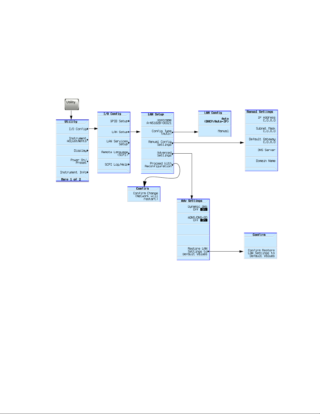
Use a 100Base-T LAN cable to connect
the signal generator to the LAN.
For details on using the instrument
remotely, see the Programming Guide.
For details on a key, press Help and then the desired key.
Configuring for Remote Control
Configuring for Remote Control
LAN Configuration
Configuring the LAN Interface
Keysight CXG, EXG, and MXG X-Series Signal Generators Getting Started Guide 21
Page 22
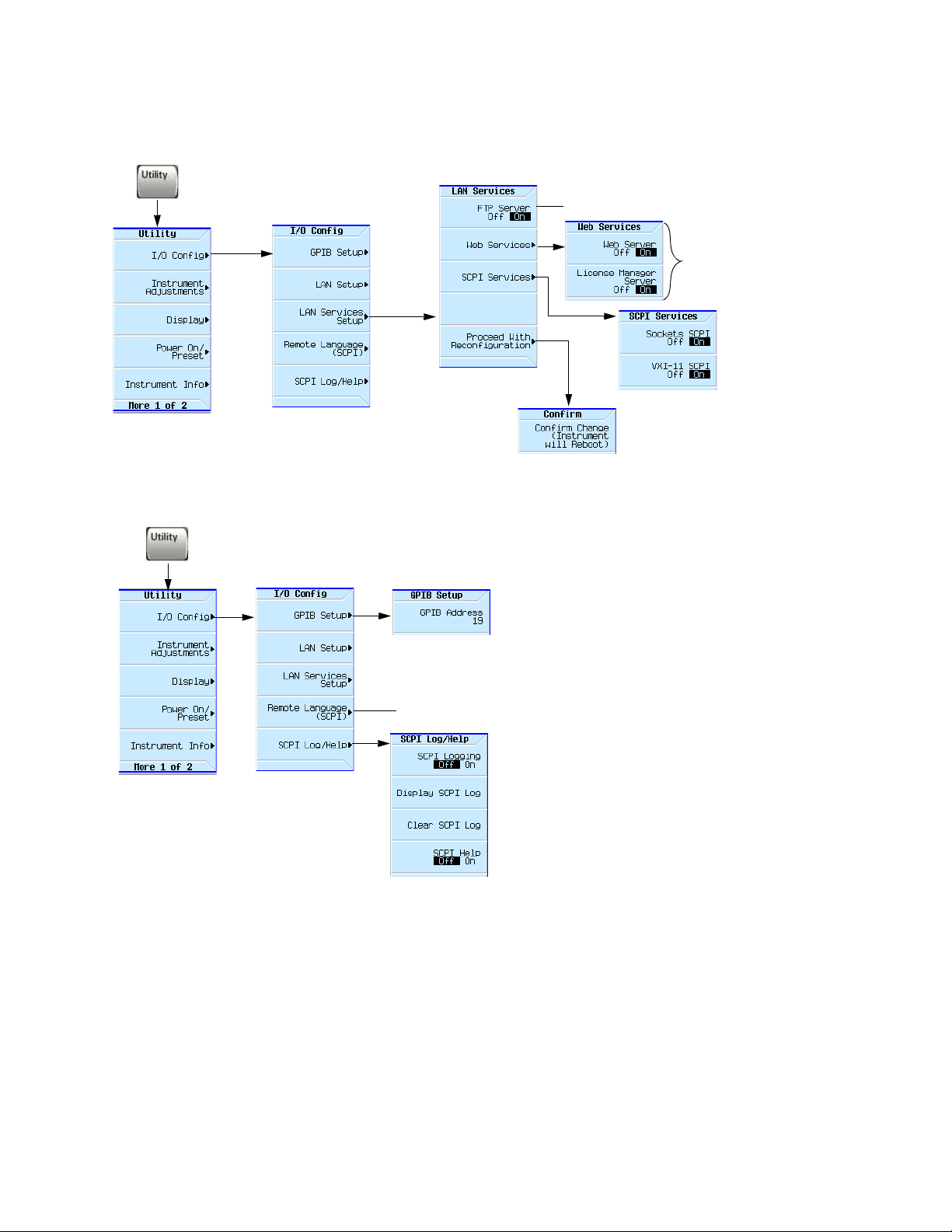
Getting Started
Use a
browser
to control
the signal
generator
Use a browser to view signal generator files.
For details on a key, press Help and then the desired key.
Select the desired GPIB language.
See also the Programming Guide and the SCPI Command Reference.
NOTES
USB is also available. It is not shown in the menu because it requires no configuration.
For details on using the instrument remotely, see the Programming Guide.
Configuring for Remote Control
Enabling LAN Services: Browser, Sockets, and VXI-11
GPIB Configuration
22 Keysight CXG, EXG, and MXG X-Series Signal Generators Getting Started Guide
Page 23
Getting Started
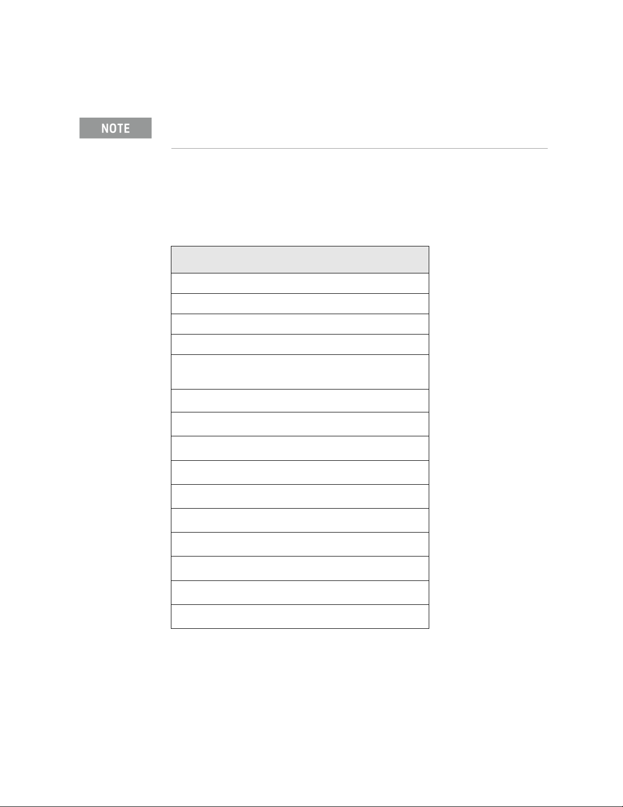
Ordering Accessories
Ordering Accessories
Only Keysight approved accessories should be used.
You can purchase accessories and find the latest documentation at:
http://www.keysight.com/find/mxg
If you do not have access to the Internet, please contact your Keysight field
engineer.
See also, “Contacting Keysight” on page 26.
Description
Rack Mount Kit 1CM110A
Rack Mount Kit with Handles 1CP104A
Rack Slide Kit 1CR112A
Front Handle Kit 1CN106A
Transit Case (See
page 24
CXG Data Sheet (N5166B)
EXG Data Sheet (N5171B/72B/73B)
MXG Data Sheet (N5181B/82B/83B)
Getting Started Guide
User’s Guide
SCPI Reference
Programming Guide
a
Figure 2-2 on
)
b
b
b
b
b
b
b
Part Number
N5180-80053
5992-3959EN
5991-0039EN
5991-0038EN
N5180-90054
N5180-90056
N5180-90057
N5180-90074
Programming Compatibility Guide
Service Guide
Error Messages Guide
b
b
b
N5180-90069
N5180-90059
N5180-90075
a. For a description of the contents of each guide and
reference, see page 7.
b. Always refer to www.keysight.com for the
most up-to-date documentation.
Keysight CXG, EXG, and MXG X-Series Signal Generators Getting Started Guide 23
Page 24
Getting Started
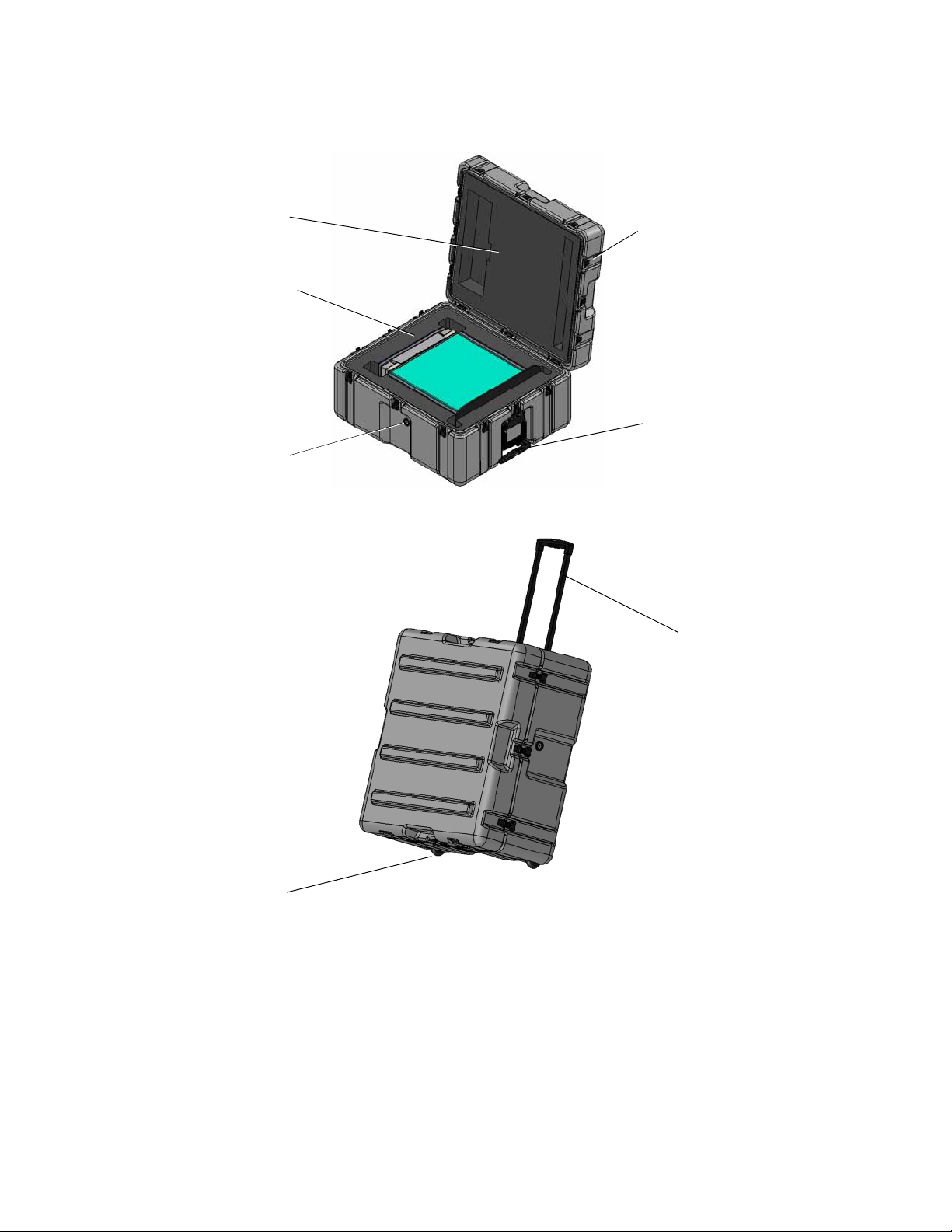
Lid Insert
Base Insert
Standard PRV
Rotomold Case - Black
Standard Plastic Handl
Ordering Accessories
Figure 2-2 Transit Case
Retractable Handle
Casters
24 Keysight CXG, EXG, and MXG X-Series Signal Generators Getting Started Guide
Page 25
Getting Started
Proper Use and Cleaning
Proper Use and Cleaning
The signal generator cover protects against physical contact with internal
assemblies that contain hazardous voltages, but does not protect internal
assemblies against contact with liquids. To avoid damage and personal injury,
ensure that liquids are positioned away from the signal generator.
Personal injury may result if the signal generator is not used as specified.
Unspecified use impairs the protection provided by the equipment. The signal
generator must be used with all means for protection intact.
Cleaning Suggestions
To prevent electrical shock, disconnect the instrument from mains before
cleaning. Use a dry cloth or one slightly dampened with water to clean the
external case parts. Do not attempt to clean internally.
Cleaning connectors with alcohol shall only be done with the instruments power
cord removed, and in a well-ventilated room. Allow all residual alcohol moisture
to evaporate, and the fumes to dissipate prior to energizing the instrument.
To ensure good connections, regularly clean the instrument’s front and rear
panel connectors with alcohol.
To prevent dust build-up that could potentially obstruct ventilation,
periodically clean the instrument’s cover. Use a dry cloth or a cloth slightly
dampened with water to clean the external case parts.
Returning a Signal Generator to Keysight Technologies
1. Gather as much information as possible about the signal generator’s
problem.
2. Contact Keysight using the phone number that is specific to your
geographic location. These phone numbers are listed on the Internet at
http://www.keysight.com/find/assist. If you do not have access to the
Internet, contact your Keysight field engineer.
After you provide information about the signal generator and its condition,
you will receive information about where to ship your signal generator for
repair.
3. Ship the signal generator in the original factory packaging materials, if
available, or use similar packaging to properly protect the signal
generator.
Keysight CXG, EXG, and MXG X-Series Signal Generators Getting Started Guide 25
Page 26

Getting Started
Contacting Keysight
Contacting Keysight
Assistance with test and measurements needs, information on finding a local
Keysight office, and information on purchasing accessories and documentation
are available on the Internet at: http://www.keysight.com/find/assist
If you do not have access to the Internet, please contact your Keysight field
engineer.
In correspondence or telephone conversation, refer to the signal generator by its
model number and full serial number. With this information, the Keysight
representative can determine if your unit is still within its warranty period.
26 Keysight CXG, EXG, and MXG X-Series Signal Generators Getting Started Guide
Page 27
Keysight Technologies
X-Series Signal Generators
Getting Started Guide
3 Operation Verification
To avoid damaging or degrading the performance of the signal generator, do not
exceed 27 dBm (0.5W) for N5173B/83B models, or 33 dBm (2W) for
N5166B/71B/72B/81B/82B models, or maximum of reverse power levels at the
RF input. See also Tips for Preventing Signal Generator Damage on
www.keysight.com.
For the instrument to meet performance specifications allow a warm up period of
45 minutes within an operational temperature range of 0 to 55 °C. For more
information, refer to the CXG, EXG, and MXG signal generator Data Sheets.
Operation verification is a series of tests used to confirm that the signal
generator is operating properly, or to diagnose problems. Operation
verification does not verify performance to instrument specifications.
Perform operation verification when you initially set up the signal generator,
after a minor repair (refer to the Service Guide for details), or when the
integrity of the signal generator is in question.
— Running Self Test on page 28
— Frequency Range and Accuracy Check on page 30
— Checking the Output Power on page 32
27
Page 28
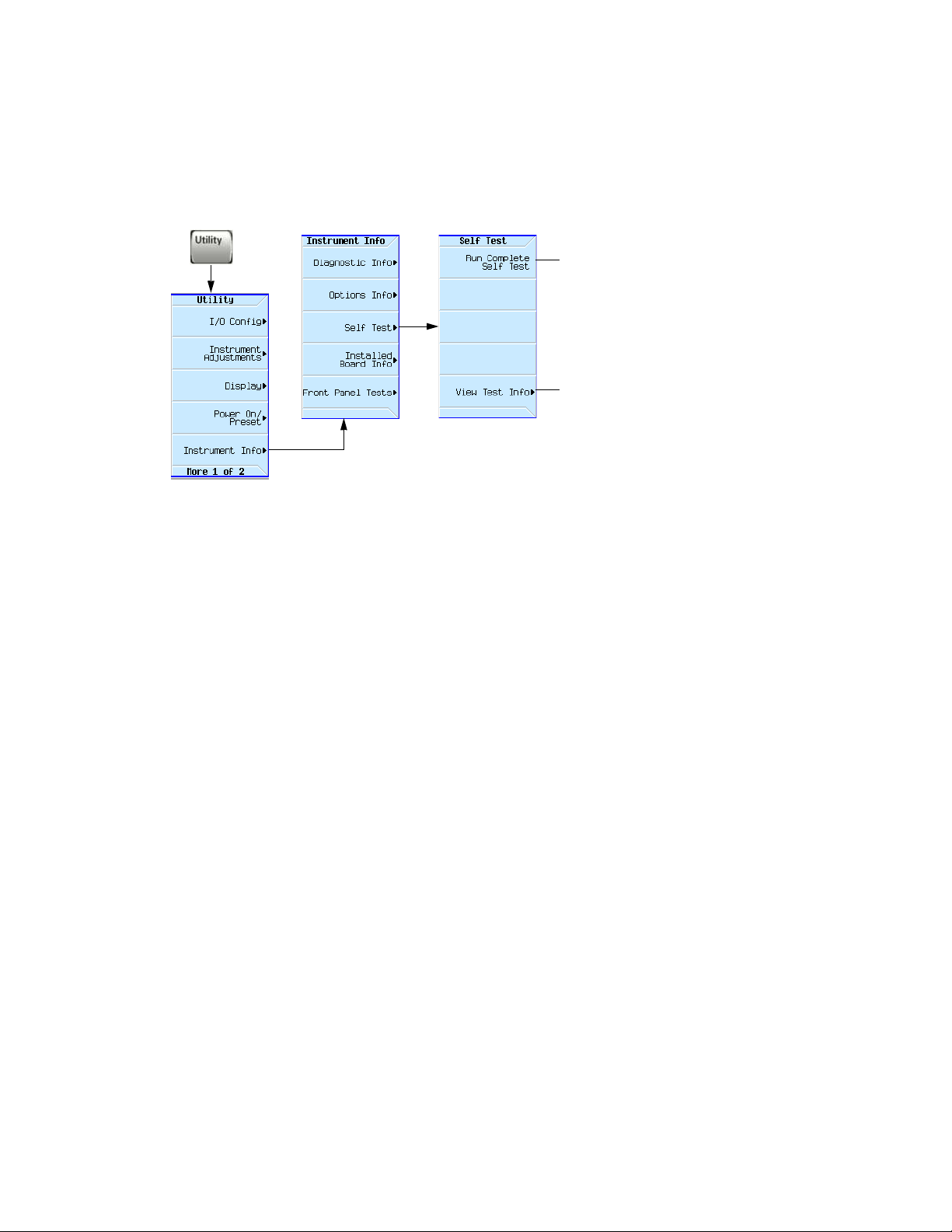
Running Self Test
It takes about 5 minutes to run the self
test.
Opens a table in which you can select specific
tests and view details of those test.
Operation Verification
Running Self Test
Self Test is a series of internal tests of signal generator functions. If this test
fails, refer to “Self Test Failure” on page 29 for further instructions.
Use the following procedure to run self test:
1. Disconnect all external cables, including GPIB, LAN, and USB cables.
2. Preset the signal generator: Press Preset > Utility > Instrument Info > Self
Test.
The following message appears:
— The current status of the self-test is: In complete.
Not all tests have been run.
3. Press Run Complete Self Test.
An activity bar displays on the screen indicating the test progress.
If you press Abort while self-test is running, the following message displays:
— The current status of the self-test is: Incom plete.
Not all tests have been run.
When self-test completes, one of the following messages displays:
— The current status of the self-test is : Passed
— The current status of the self-test is : Failure. One
or more tests have failed. System diag nostics
indicate this test as the root failure : xxx
If the signal generator fails only one test, the title of the failed test displays.
If the signal generator fails more than one test, the test number of the most
significant failure (root failure) displays.
28 Keysight CXG, EXG, and MXG X-Series Signal Generators Getting Started Guide
Page 29
Operation Verification
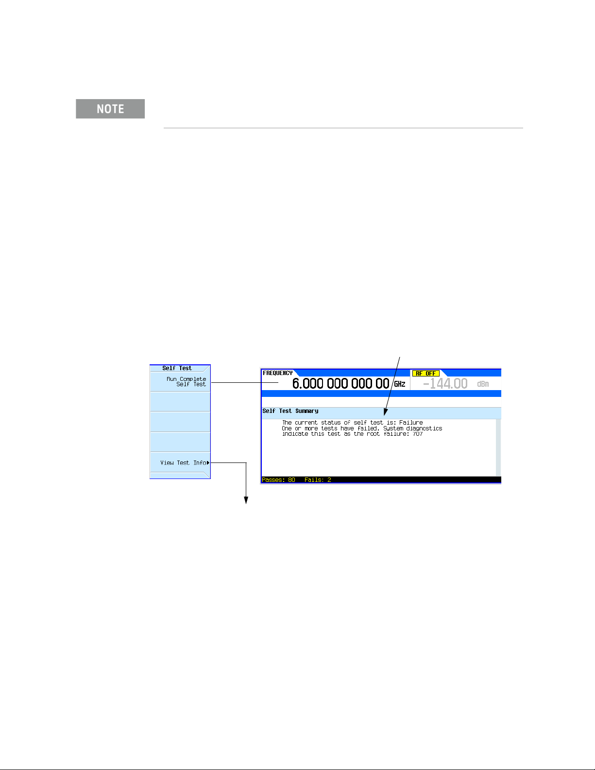
If Self Test fails, the summary indicates the
most significant failure (root failure).
Utility > Instrument Info >
Self Test
This information is supplemental. Please disregard unless Keysight specifically requests this information.
Running Self Test
NOTE The root failure is the error to report to Keysight Support.
Self Test Failure
1. Confirm that all external cables, including GPIB, LAN, and USB cables, are
disconnected from the signal generator and repeat the self-test.
2. If the self-test continues to fail, the signal generator requires service. If
you are unable to service the signal generator, send it to an Keysight
service center for repair. Include a detailed description of the most
significant failure (root failure) and any displayed error messages.
Also include the model, serial number, installed options, and firmware
version.
See “Returning a Signal Generator to Keysight Technologies” on page 25
for return instructions.
Refer to “Contacting Keysight” on page 26.
Viewing Test Results
Keysight CXG, EXG, and MXG X-Series Signal Generators Getting Started Guide 29
Page 30
Operation Verification
Frequency Range and Accuracy Check
Frequency Range and Accuracy Check
The frequency range is tested by determining the frequency accuracy relative
to the timebase at the frequency limits of the signal generator. This test can be
performed with a frequency counter that meets the frequency accuracy limits
in Table 3-1.
Frequency Counter Procedure
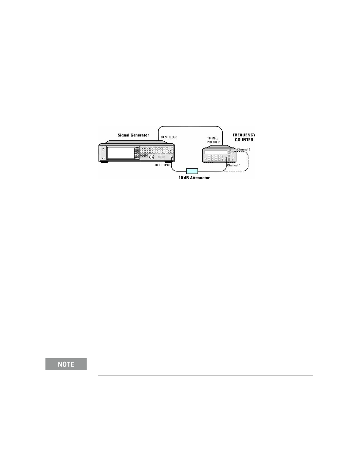
Test Setup 1. Connect the equipment as shown.
2. Preset the signal generator: Press Preset.
3. Turn modulation off: Press the Mod On/Off so that the MOD On/Off LED
turns off.
4. Set the amplitude:
Press Amplitude and enter 0 dBm.
5. Turn RF on: Press RF On/Off so that the RF On/Off LED lights.
6. Verify that the frequency counter is locked to the 10 MHz external
reference frequency (±1 Hz).
7. For maximum accuracy, set the gate time on the frequency counter to >5
seconds.
(For example, press Gate & ExtArm twice and use the arrow keys to set the
value.)
8. Set the frequency: Press Frequency and set the signal generator to the
first frequency listed in Table 3-1 .
9. Confirm that the measured frequency is within the limits listed.
10.Repeat step 8 and step 9 for all of the frequencies in the table that are
within the frequency range of your signal generator.
For frequencies <200 MHz, use Channel 3 on the frequency counter
(press Freq Ratio until
CH3: displays).
30 Keysight CXG, EXG, and MXG X-Series Signal Generators Getting Started Guide
Page 31
Operation Verification
Frequency Range and Accuracy Check
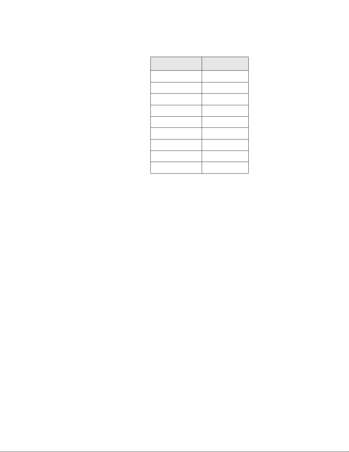
Table 3-1 Frequency Accuracy Limits
Frequency (MHz) Limit (Hz)
0.01 MHz ±2
0.1 MHz ±2
200 MHz ±2
300 MHz ±2
500 MHz ±2
1000 MHz ±2
2000 MHz ±2
3100 MHz ±2
6000 MHz ±2
Keysight CXG, EXG, and MXG X-Series Signal Generators Getting Started Guide 31
Page 32
Operation Verification
Checking the Output Power
Troubleshooting Problems with the Frequency Accuracy Check
— Verify the cables are connected correctly.
— If you are using a frequency counter, verify that you are using the correct
channel for the frequencies you are measuring.
Checking the Output Power
This test verifies that the CW output power from the signal generator is within
defined limits. The following table lists the preferred equipment for this test.
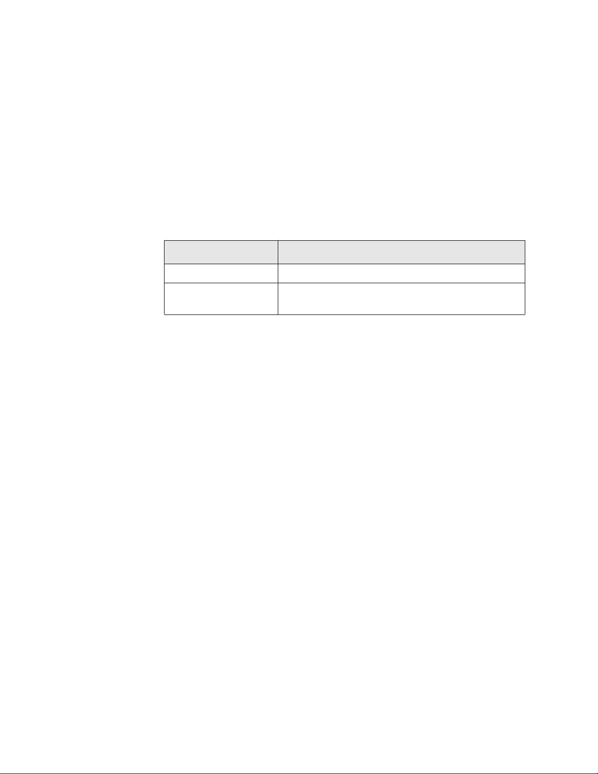
Test Equipment Recommended Model
Power Meter Keysight E4418B or E4419A/B E-Series or equivalent
Power Sensor,
Input: Type-N (m)
Keysight E9304A
— N5171B/81B Test Procedure on page 33
— N5171B/81B Alternative Test Procedure on page 34
— N5166B/72B/82B Test Procedure on page 36
— N5166B/72B/82B Alternative Test Procedure on page 39
— N5173B/83B Test Procedure on page 40
— N5173B/83B Alternative Test Procedure on page 41
If this test fails, refer to “Troubleshooting Problems with the Output Power
Check” on page 43 for further instructions.
32 Keysight CXG, EXG, and MXG X-Series Signal Generators Getting Started Guide
Page 33
Operation Verification
Checking the Output Power
N5171B/81B Test Procedure
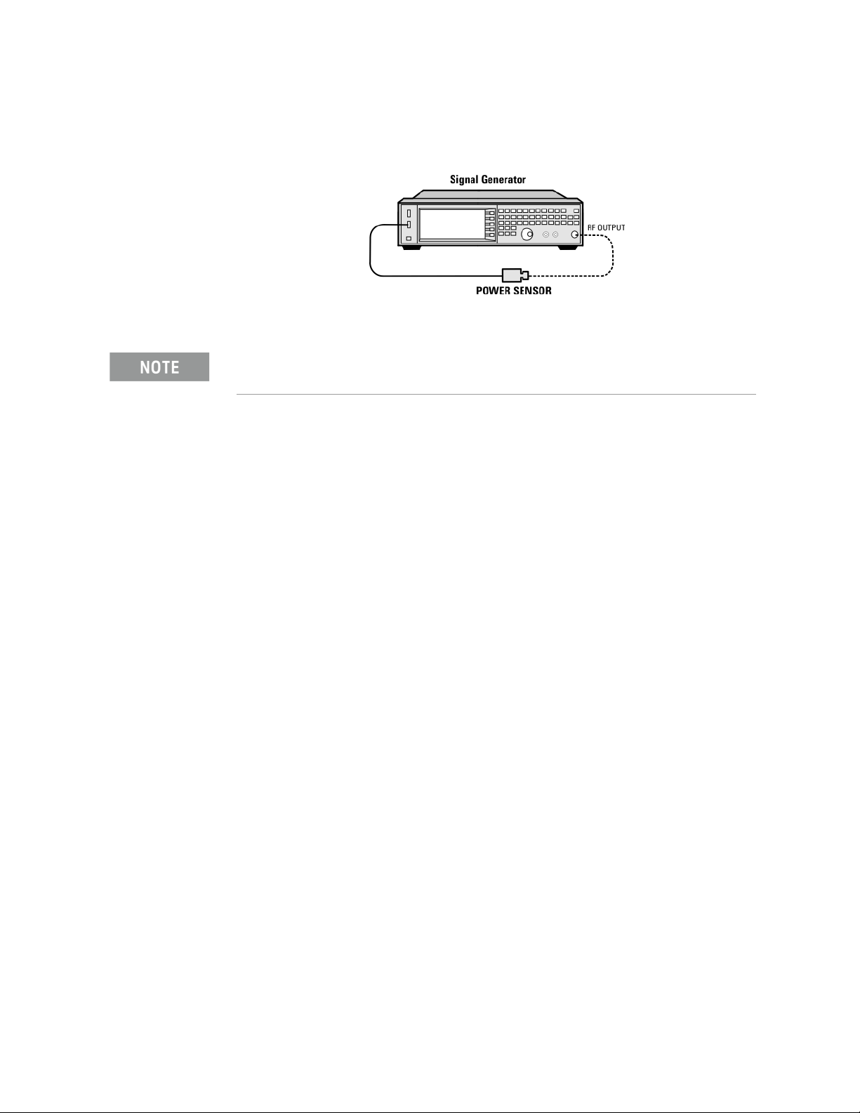
Test Setup 1. Connect the equipment as shown:
2. Zero and calibrate the power sensor.
USB U2000A Series Power Sensors do not require the sensor to be zeroed or
calibrated.
3. Connect the power sensor to the RF output of the signal generator. Once
the LED on the power sensor turns off, the sensor is ready to measure.
4. Preset the signal generator: Press Preset
5. Turn the internal power meter channel on: Press Aux Fctn > Power Meter
Measurements > Channel A On (or Channel B On).
6. Turn RF on: Press RF On/Off so that the RF On/Off LED lights.
7. Turn modulation off: Press Mod On/Off so that the Mod On/Off LED turns
off.
8. Set the frequency: Press Frequency and enter the first frequency value
listed in Tab le 3-2.
9. Set the amplitude: Press Amplitude and enter the amplitude value for that
frequency.
10.Measure the output power level.
11.Repeat steps 8 through 10 to measure power at each of the frequencies
listed in Tab le 3-2.
12.Confirm that the measured power levels are within the limits listed in the
table.
Keysight CXG, EXG, and MXG X-Series Signal Generators Getting Started Guide 33
Page 34
Operation Verification
Checking the Output Power
N5171B/81B Alternative Test Procedure
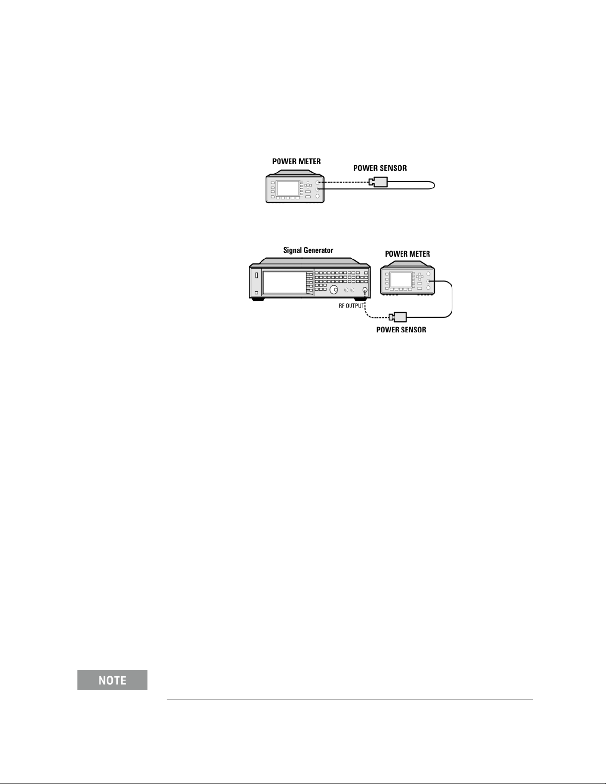
If a USB power sensor is not available, use a power meter to measure the
output power of the signal generator.
Test Setup 1. Zero and calibrate the power sensor to the power meter:
2. Connect the equipment as shown:
3. Preset the signal generator: Press Preset.
4. Turn RF on: Press RF On/Off so that the RF On/Off LED lights.
5. Turn modulation off: Press Mod On/Off so that the Mod On/Off LED turns
off.
6. Set the frequency: Press Frequency and enter the first frequency value
listed in Tab le 3-2.
7. Set the amplitude: Press Amplitude and enter the amplitude value for that
frequency.
8. Configure the power meter for the measurement.
a. Press the Frequency Cal Fac button on the power meter.
b. Select a power meter channel (if applicable).
c. Use the arrow keys to enter the frequency at which to measure the
power.
9. Measure the output power level.
10.Repeat steps 6 through 9 to measure power at each of the 15 frequencies
listed in Tab le 3-2.
11.Confirm that the measured power levels are within the limits listed in the
table.
Limit values are due to power meter uncertainty.
34 Keysight CXG, EXG, and MXG X-Series Signal Generators Getting Started Guide
Page 35
Operation Verification
Checking the Output Power
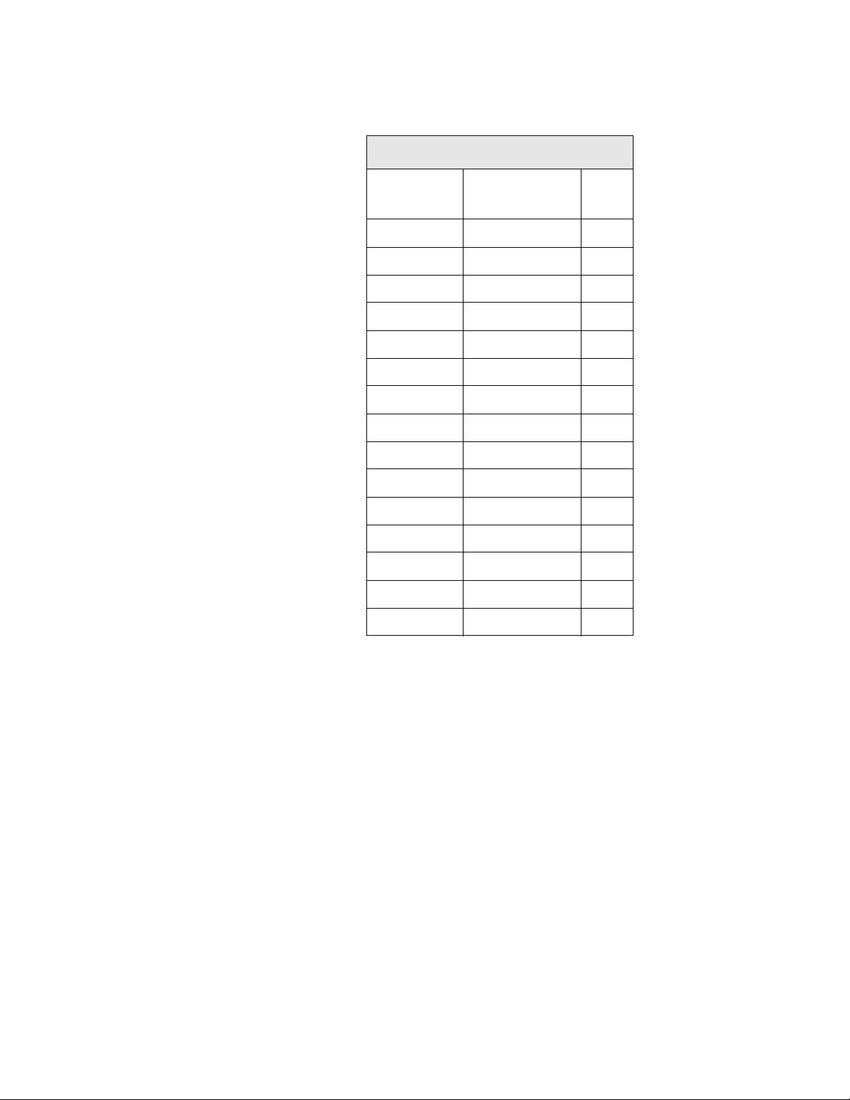
Table 3-2 Leveled Output Power Limits
N5171B/81B Output Power
Frequency Amplitude (dBm) Limits
125 MHz 7 ±2
275 MHz 7 ±2
338 MHz 7 ±2
425 MHz 7 ±2
538 MHz 7 ±2
675 MHz 7 ±2
850 MHz 7 ±2
1075 MHz 7 ±2
1350 MHz 7 ±2
(dB)
1700 MHz 7 ±2
2150 MHz 7 ±2
2700 MHz 7 ±2
3400 MHz 7 ±2
4300 MHz 7 ±2
5400 MHz 7 ±2
Keysight CXG, EXG, and MXG X-Series Signal Generators Getting Started Guide 35
Page 36
Operation Verification
Checking the Output Power
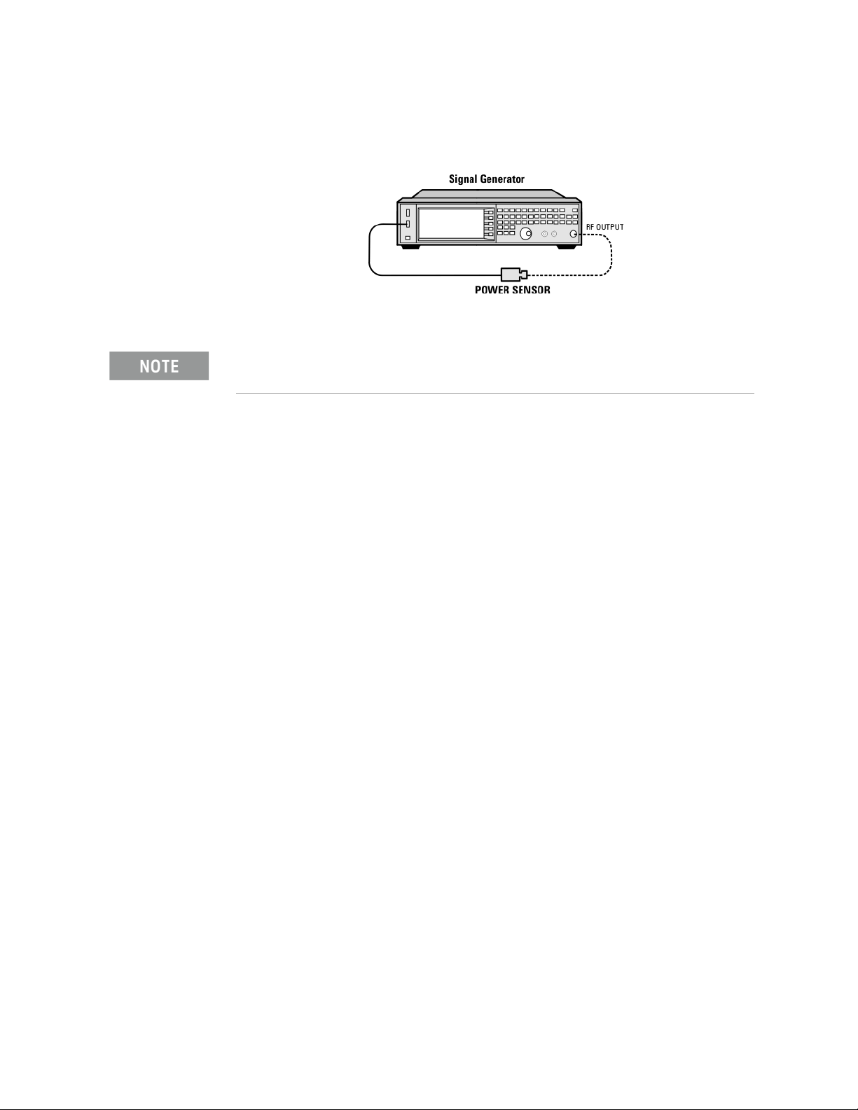
N5166B/72B/82B Test Procedure
Test Setup 1. Connect the equipment as shown:
2. Zero and calibrate the power sensor.
USB U2000A Series Power Sensors do not require the sensor to be zeroed or
calibrated.
3. Connect the power sensor to the RF output of the signal generator. Once
the LED on the power sensor turns off, the sensor is ready to measure.
Without
Modulation
4. Preset the signal generator: Press Preset
5. Turn the internal power meter channel on: Press Aux Fctn > Power Meter
Measurements > Channel A On (or Channel B On).
6. Turn RF on: Press RF On/Off so that the RF On/Off LED lights.
7. Turn modulation off: Press Mod On/Off so that the Mod On/Off LED turns
off.
8. Set the frequency: Press Frequency and enter the first frequency value
listed in Tab le 3-3.
9. Set the amplitude: Press Amplitude and enter the amplitude value for that
frequency.
10.Measure the output power level.
11.Repeat steps 8 through 10 to measure power at each of the frequencies
listed in Tab le 3-3.
12.Confirm that the measured power levels are within the limits listed in the
table.
a. Set the signal generator frequency to the first value listed in Table
3-3:
Press Frequency > 250 > MHz.
b. Set the amplitude to 7 dBm:
Press Amplitude > 7 > dBm.
c. If using a power meter, configure the power meter as follows:
36 Keysight CXG, EXG, and MXG X-Series Signal Generators Getting Started Guide
Page 37
Operation Verification
Checking the Output Power
1. On the power meter, press the Frequency Cal Fac button.
2. If applicable, select a power meter channel.
3. Use the arrow keys to enter the frequency at which to
measure the power.
d. Measure the output power level.
e. Repeat steps a through d for the remaining frequencies in the table,
and confirm that the power level at each point is within limits.
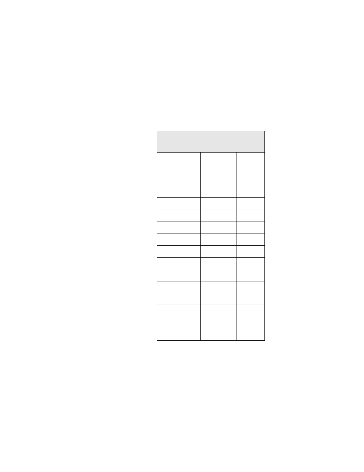
Table 3-3 Output Power without Modulation
N5166B/72B/82B Output Power without
Modulation
Frequency
(MHz)
250 7 ±2
338 7 ±2
425 7 ±2
538 7 ±2
675 7 ±2
850 7 ±2
1075 7 ±2
1350 7 ±2
1700 7 ±2
2150 7 ±2
2700 7 ±2
3400 7 ±2
4300 7 ±2
Amplitude
(dBm)
Limits
(dB)
5400 7 ±2
With Modulation 13.Preset the signal generator: Press Preset.
14.Select the factory-supplied waveform SINE_TEST_WFM:
a. Press Mode > Dual ARB > Select Waveform.
b. Highlight the SINE_TEST_WFM waveform.
c. Press Select Waveform.
15.Turn the arbitrary waveform player on: Press the ARB softkey to highlight
On.
Keysight CXG, EXG, and MXG X-Series Signal Generators Getting Started Guide 37
Page 38
Operation Verification
Checking the Output Power
16.Set the frequency to the first value listed in Table 3-4 :
Press Frequency > 250 > MHz.
17.Set the amplitude to 7 dBm:
Press Amplitude > 7 > dBm.
18.If using a power meter, configure the power meter as follows:
a. On the power meter, press the Frequency Cal Fac button.
b. Select a power meter channel (if applicable).
c. Use the arrow keys to enter the frequency at which to measure the
power.
19.Measure the output power.
20.Repeat steps 16 through 19 for the remaining frequencies listed in
Table 3-4, and confirm that the power level at each point is within limits.
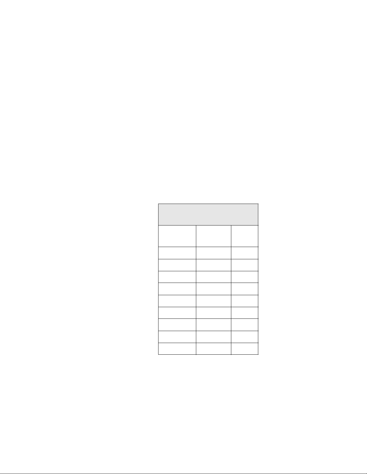
Table 3-4 Output Power with Modulation
N5166B/72B/82B Output Power with
Modulation
Frequency
(MHz)
250 7 ±2
323 7 ±2
512 7 ±2
814 7 ±2
1275 7 ±2
2025 7 ±2
2750 7 ±2
3750 7 ±2
5250 7 ±2
Amplitude
(dBm)
Limits
(dB)
38 Keysight CXG, EXG, and MXG X-Series Signal Generators Getting Started Guide
Page 39
Operation Verification
Checking the Output Power
N5166B/72B/82B Alternative Test Procedure
If a USB power sensor is not available, use a power meter to measure the
output power of the signal generator.
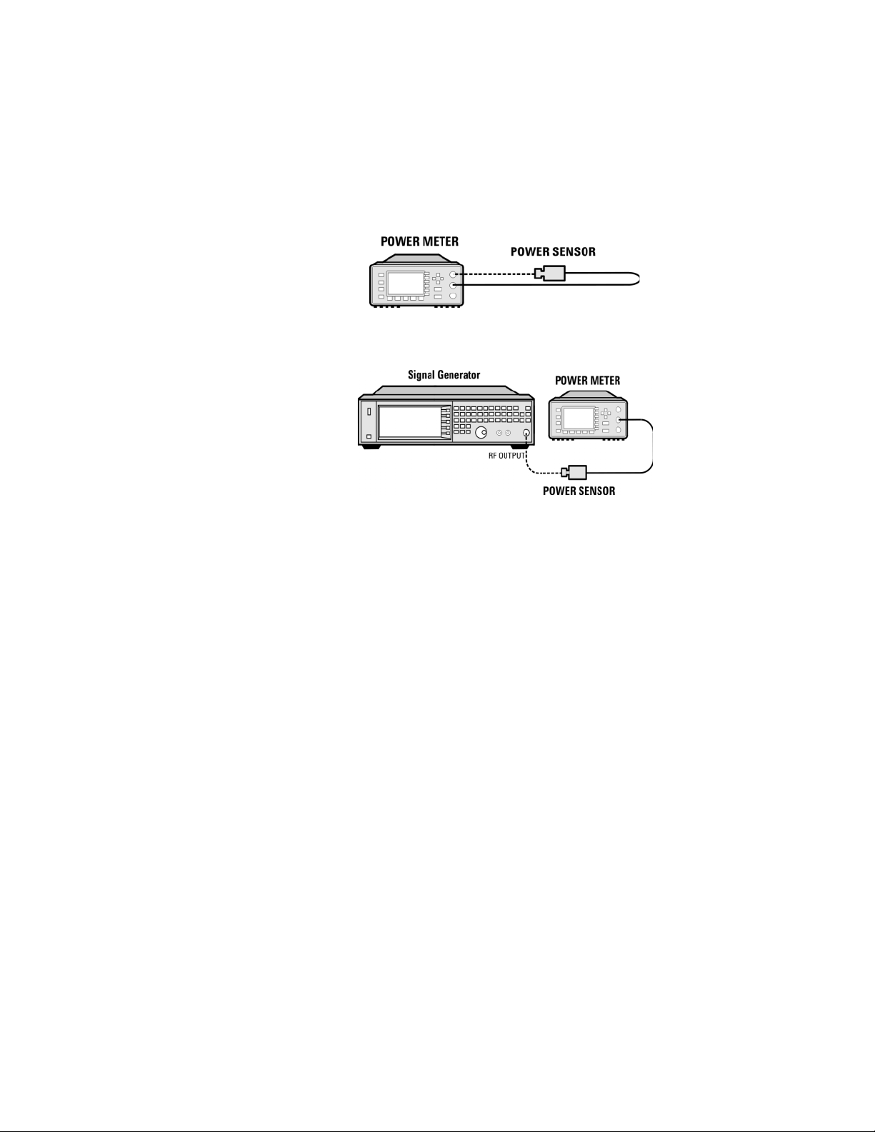
Test Setup 1. Zero and calibrate the power sensor to the power meter:
2. Connect the equipment as shown below:
3. Preset the signal generator: Press Preset.
4. Turn RF on: Press RF On/Off so that the RF On/Off LED lights.
5. Turn modulation off:
Press Mod On/Off so that the Mod On/Off LED turns off.
6. Continue the procedure from “Without Modulation” on page 36.
7. Continue the procedure from “With Modulation” on page 37 to complete
the output power measurements of the N5166B/72B/82B.
Keysight CXG, EXG, and MXG X-Series Signal Generators Getting Started Guide 39
Page 40
Operation Verification
Checking the Output Power
N5173B/83B Test Procedure
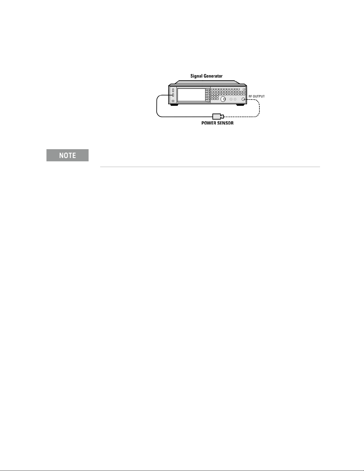
Test Setup 1. Connect the equipment as shown:
2. Zero and calibrate the power sensor.
USB U2000A Series Power Sensors do not require the sensor to be zeroed or
calibrated.
3. Connect the power sensor to the RF output of the signal generator. Once
the LED on the power sensor turns off, the sensor is ready to measure.
4. Preset the signal generator: Press Preset
5. Turn the internal power meter channel on: Press Aux Fctn > Power Meter
Measurements > Channel A On (or Channel B On).
6. Turn RF on: Press RF On/Off so that the RF On/Off LED lights.
7. Turn modulation off: Press Mod On/Off so that the Mod On/Off LED turns
off.
8. Set the frequency: Press Frequency and enter the first frequency value
listed in Tab le 3-6.
9. Set the amplitude: Press Amplitude and enter the amplitude value for that
frequency.
10.Measure the output power level.
11.Repeat steps 8 through 10 to measure power at each of the frequencies
listed in Tab le 3-6.
12.Confirm that the measured power levels are within the limits listed in the
table.
40 Keysight CXG, EXG, and MXG X-Series Signal Generators Getting Started Guide
Page 41
Operation Verification
*Refer to
*Refer to
Checking the Output Power
N5173B/83B Alternative Test Procedure
If a USB power sensor is not available, use a power meter to measure the
output power of the signal generator.
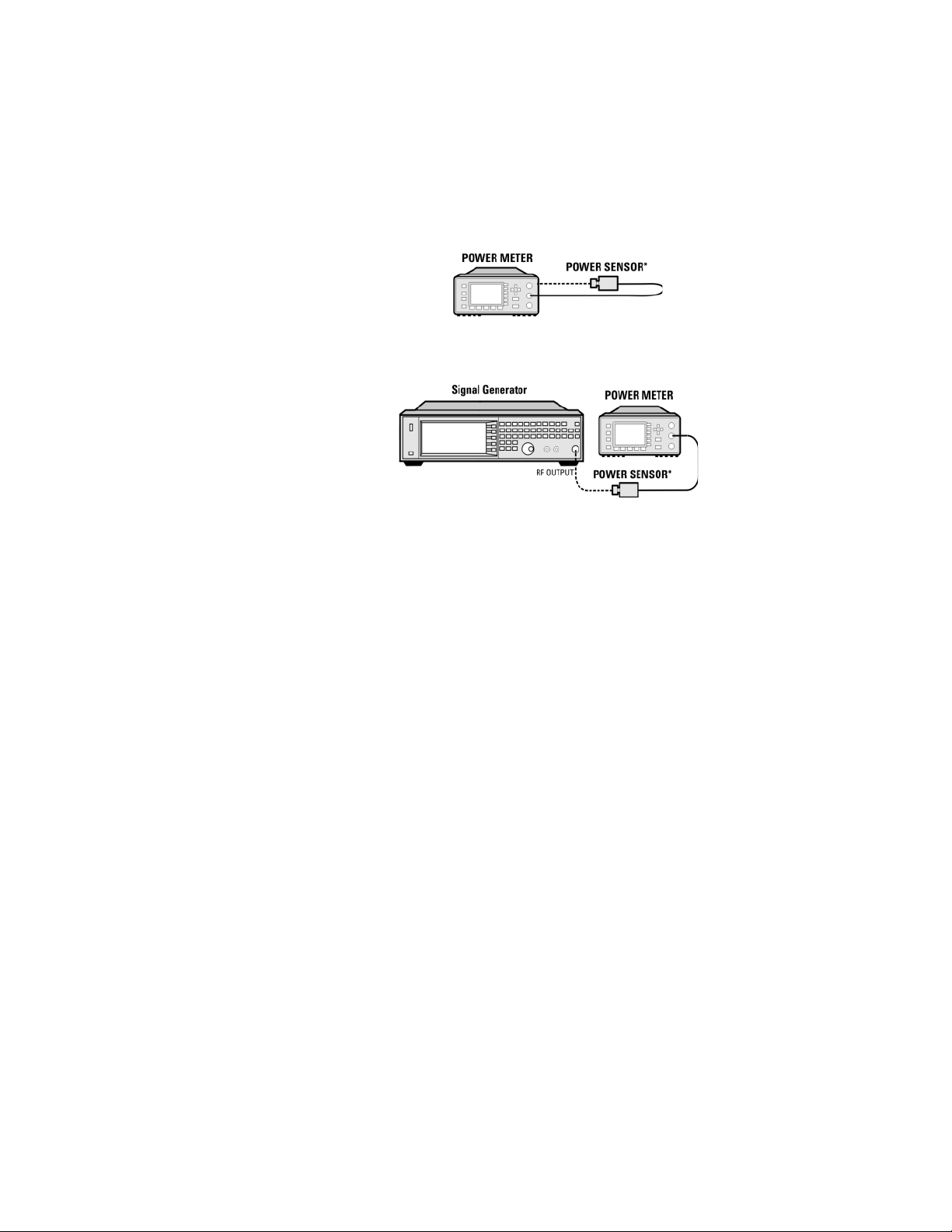
Test Setup 1. Zero and calibrate the power sensor to the power meter:
2. Connect the equipment as shown:
3. Preset the signal generator: Press Preset.
4. Turn RF on: Press RF On/Off so that the RF On/Off LED lights.
5. Turn modulation off: Press Mod On/Off so that the Mod On/Off LED turns
off.
6. Set the frequency: Press Frequency and enter the first frequency value
listed in Tab le 3-6.
7. Set the amplitude: Press Amplitude and enter the amplitude value for that
frequency.
8. Configure the power meter for the measurement.
a. Press the Frequency Cal Fac button on the power meter.
b. Select a power meter channel (if applicable).
c. Use the arrow keys to enter the frequency at which to measure the
power.
9. Measure the output power level.
10.Repeat steps 6 through 9 to measure power at each of the 15 frequencies
listed in Tab le 3-6.
11.Confirm that the measured power levels are within the limits listed in the
table.
Keysight CXG, EXG, and MXG X-Series Signal Generators Getting Started Guide 41
Page 42
Operation Verification
Checking the Output Power
Table 3-5 Power Sensors by Frequency and Options
N5173B/83B Frequency Power Sensor
Option 513/520/540 < 5GHz E9304A
Option 520 > 5GHz 8485A
Option 532/540 > 5GHz 8487A
Table 3-6 Leveled Output Power Limits
N5173B/83B Output Power
Frequency Amplitude (dBm) Standard
Power
513/520 532/540 513/520 532/540
200 MHz 11 7 15 14 ±2
300 MHz 11 7 15 14 ±2
500 MHz 11 7 15 14 ±2
800 MHz 11 7 15 14 ±2
1.0 GHz 11 7 15 14 ±2
2.0 GHz 11 7 15 14 ±2
3.1 GHz 11 7 15 14 ±2
5.0 GHz 11 7 18 14 ±2
10 GHz 11 7 18 14 ±2
20 GHz
(Option
520)
31.8 GHz
(Option
532)
-- 7 -- 13 ±2
-- 7 -- 13 ±2
Amplitude (dBm) Option
1EA
Limits
ab
(dB)
40 GHz
(Option
540)
-- 7 -- 12 ±2
a. Limit values are due to power meter uncertainty.
b. For questions around measurement uncertainty, refer to the Data Sheet.
42 Keysight CXG, EXG, and MXG X-Series Signal Generators Getting Started Guide
Page 43

Operation Verification
Checking the Output Power
Troubleshooting Problems with the Output Power Check
— Verify that you are using the appropriate power sensor.
— Normally, power sensor calibration factors are automatically downloaded to
the power meter when the power meter turns on. If this does not occur,
manually enter the correct calibration factors for the power sensor you are
using.
— Verify that the power sensor is properly calibrated to the power meter.
Keysight CXG, EXG, and MXG X-Series Signal Generators Getting Started Guide 43
Page 44

Operation Verification
Checking the Output Power
44 Keysight CXG, EXG, and MXG X-Series Signal Generators Getting Started Guide
Page 45

Keysight Technologies
X-Series Signal Generators
Getting Started Guide
4 Regulatory Information
— General on page 46
— Certification on page 46
— Assistance on page 46
— Statement of Compliance on page 46
— Compliance with Canadian EMC Requirements on page 46
— South Korean Class A EMC Declaration on page 47
— Compliance with European Machinery Directive Acoustic Requirement on
page 47
45
Page 46

General
Certification
Regulatory Information
General
This product has been designed and tested in accordance with accepted
industry standards, and has been supplied in a safe condition. The
documentation contains information and warnings that must be followed by
the user to ensure safe operation and to maintain the product in a safe
condition.
Keysight Technologies certifies that this product met its published
specifications at the time of shipment from the factory. Keysight Technologies
further certifies that its calibration measurements are traceable to the United
States National Institute of Standards and Technology, to the extent allowed
by the Institute’s calibration facility, and to the calibration facilities of other
International Standards Organization members.
Assistance
Product maintenance agreements and other customer assistance agreements
are available for Keysight Technologies products. For assistance, contact
Keysight Technologies (see page 26).
Statement of Compliance
This product(s) complies with applicable Safety and EMC regulations and
directives. A copy of the manufacturer’s Declaration of Conformity for this
product(s) can be obtained by contacting your local Keysight Technologies
sales representative.
Compliance with Canadian EMC Requirements
This ISM device complies with Canadian ICES-001.
Cet appareil ISM est conforme a la norme NMB du Canada.
46 Keysight CXG, EXG, and MXG X-Series Signal Generators Getting Started Guide
Page 47
Regulatory Information
South Korean Class A EMC Declaration
South Korean Class A EMC Declaration
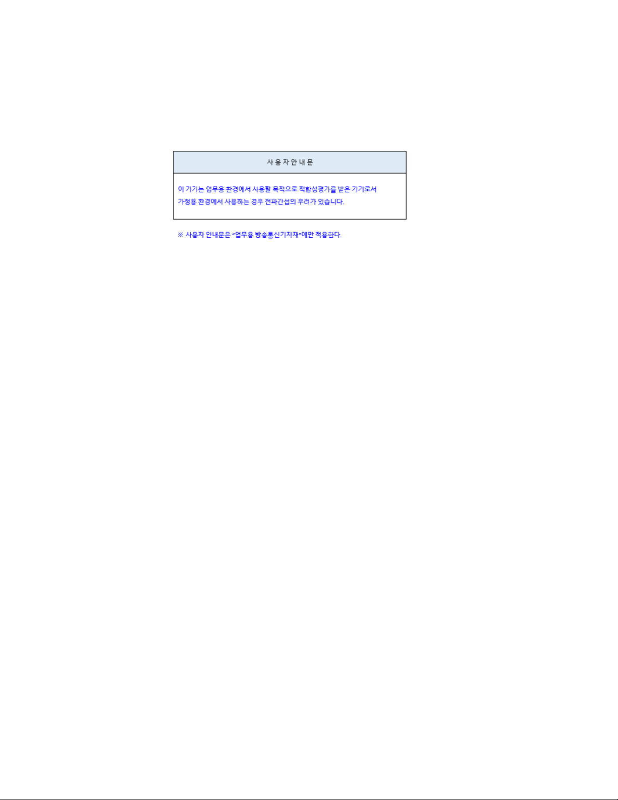
This equipment has been conformity assessed for use in business
environments. In a residential environment this equipment may cause radio
interference.
Compliance with European Machinery Directive Acoustic Requirement
Table 4-1
Acoustic statement (European Machinery Directive 2002/42/EC, 1.7.4.2u)
Acoustic noise emission
LpA < 70 dB
Operator position
Normal operation mode
Keysight CXG, EXG, and MXG X-Series Signal Generators Getting Started Guide 47
Page 48

Regulatory Information
Compliance with European Machinery Directive Acoustic Requirement
48 Keysight CXG, EXG, and MXG X-Series Signal Generators Getting Started Guide
Page 49

Keysight Technologies
X-Series Signal Generators
Getting Started Guide
5 Open Source Licenses
This chapter contains the licenses for open source software used in the
Keysight CXG, MXG and EXG X-Series signal generators.
49
Page 50

Open Source Licenses
Apple mDNSresponder
Apple mDNSresponder
Apache License
Version 2.0, January 2004
http://www.apache.org/licenses/
TERMS AND CONDITIONS FOR USE, REPRODUCTION, AND DISTRIBUTION
1. Definitions.
"License" shall mean the terms and conditions for use, reproduction,
and distribution as defined by Sections 1 through 9 of this document.
"Licensor" shall mean the copyright owner or entity authorized by
the copyright owner that is granting the License.
"Legal Entity" shall mean the union of the acting entity and all
other entities that control, are controlled by, or are under common
control with that entity. For the purposes of this definition,
"control" means (i) the power, direct or indirect, to cause the
direction or management of such entity, whether by contract or
otherwise, or (ii) ownership of fifty percent (50%) or more of the
outstanding shares, or (iii) beneficial ownership of such entity.
"You" (or "Your") shall mean an individual or Legal Entity
exercising permissions granted by this License.
"Source" form shall mean the preferred form for making modifications,
including but not limited to software source code, documentation
source, and configuration files.
"Object" form shall mean any form resulting from mechanical
transformation or translation of a Source form, including but
not limited to compiled object code, generated documentation,
and conversions to other media types.
"Work" shall mean the work of authorship, whether in Source or
Object form, made available under the License, as indicated by a
50 Keysight CXG, EXG, and MXG X-Series Signal Generators Getting Started Guide
Page 51

Open Source Licenses
Apple mDNSresponder
copyright notice that is included in or attached to the work
(an example is provided in the Appendix below).
"Derivative Works" shall mean any work, whether in Source or Object
form, that is based on (or derived from) the Work and for which the
editorial revisions, annotations, elaborations, or other modifications
represent, as a whole, an original work of authorship. For the purposes
of this License, Derivative Works shall not include works that remain
separable from, or merely link (or bind by name) to the interfaces of,
the Work and Derivative Works thereof.
"Contribution" shall mean any work of authorship, including
the original version of the Work and any modifications or additions
to that Work or Derivative Works thereof, that is intentionally
submitted to Licensor for inclusion in the Work by the copyright owner
or by an individual or Legal Entity authorized to submit on behalf of
the copyright owner. For the purposes of this definition, "submitted"
means any form of electronic, verbal, or written communication sent
to the Licensor or its representatives, including but not limited to
communication on electronic mailing lists, source code control systems,
and issue tracking systems that are managed by, or on behalf of, the
Licensor for the purpose of discussing and improving the Work, but
excluding communication that is conspicuously marked or otherwise
designated in writing by the copyright owner as "Not a Contribution."
"Contributor" shall mean Licensor and any individual or Legal Entity
on behalf of whom a Contribution has been received by Licensor and
subsequently incorporated within the Work.
2. Grant of Copyright License. Subject to the terms and conditions of
this License, each Contributor hereby grants to You a perpetual,
worldwide, non-exclusive, no-charge, royalty-free, irrevocable
copyright license to reproduce, prepare Derivative Works of,
Keysight CXG, EXG, and MXG X-Series Signal Generators Getting Started Guide 51
Page 52

Open Source Licenses
Apple mDNSresponder
publicly display, publicly perform, sublicense, and distribute the
Work and such Derivative Works in Source or Object form.
3. Grant of Patent License. Subject to the terms and conditions of
this License, each Contributor hereby grants to You a perpetual,
worldwide, non-exclusive, no-charge, royalty-free, irrevocable
(except as stated in this section) patent license to make, have made,
use, offer to sell, sell, import, and otherwise transfer the Work,
where such license applies only to those patent claims licensable
by such Contributor that are necessarily infringed by their
Contribution(s) alone or by combination of their Contribution(s)
with the Work to which such Contribution(s) was submitted. If You
institute patent litigation against any entity (including a
cross-claim or counterclaim in a lawsuit) alleging that the Work
or a Contribution incorporated within the Work constitutes direct
or contributory patent infringement, then any patent licenses
granted to You under this License for that Work shall terminate
as of the date such litigation is filed.
4. Redistribution. You may reproduce and distribute copies of the
Work or Derivative Works thereof in any medium, with or without
modifications, and in Source or Object form, provided that You
meet the following conditions:
(a) You must give any other recipients of the Work or
Derivative Works a copy of this License; and
(b) You must cause any modified files to carry prominent notices
stating that You changed the files; and
(c) You must retain, in the Source form of any Derivative Works
that You distribute, all copyright, patent, trademark, and
attribution notices from the Source form of the Work,
52 Keysight CXG, EXG, and MXG X-Series Signal Generators Getting Started Guide
Page 53

Open Source Licenses
Apple mDNSresponder
excluding those notices that do not pertain to any part of
the Derivative Works; and
(d) If the Work includes a "NOTICE" text file as part of its
distribution, then any Derivative Works that You distribute must
include a readable copy of the attribution notices contained
within such NOTICE file, excluding those notices that do not
pertain to any part of the Derivative Works, in at least one
of the following places: within a NOTICE text file distributed
as part of the Derivative Works; within the Source form or
documentation, if provided along with the Derivative Works; or,
within a display generated by the Derivative Works, if and
wherever such third-party notices normally appear. The contents
of the NOTICE file are for informational purposes only and
do not modify the License. You may add Your own attribution
notices within Derivative Works that You distribute, alongside
or as an addendum to the NOTICE text from the Work, provided
that such additional attribution notices cannot be construed
as modifying the License.
You may add Your own copyright statement to Your modifications and
may provide additional or different license terms and conditions
for use, reproduction, or distribution of Your modifications, or
for any such Derivative Works as a whole, provided Your use,
reproduction, and distribution of the Work otherwise complies with
the conditions stated in this License.
5. Submission of Contributions. Unless You explicitly state otherwise,
any Contribution intentionally submitted for inclusion in the Work
by You to the Licensor shall be under the terms and conditions of
this License, without any additional terms or conditions.
Notwithstanding the above, nothing herein shall supersede or modify
the terms of any separate license agreement you may have executed
Keysight CXG, EXG, and MXG X-Series Signal Generators Getting Started Guide 53
Page 54

Open Source Licenses
Apple mDNSresponder
with Licensor regarding such Contributions.
6. Trademarks. This License does not grant permission to use the trade
names, trademarks, service marks, or product names of the Licensor,
except as required for reasonable and customary use in describing the
origin of the Work and reproducing the content of the NOTICE file.
7. Disclaimer of Warranty. Unless required by applicable law or
agreed to in writing, Licensor provides the Work (and each
Contributor provides its Contributions) on an "AS IS" BASIS,
WITHOUT WARRANTIES OR CONDITIONS OF ANY KIND, either express or
implied, including, without limitation, any warranties or conditions
of TITLE, NON-INFRINGEMENT, MERCHANTABILITY, or FITNESS FOR A
PARTICULAR PURPOSE. You are solely responsible for determining the
appropriateness of using or redistributing the Work and assume any
risks associated with Your exercise of permissions under this License.
8. Limitation of Liability. In no event and under no legal theory,
whether in tort (including negligence), contract, or otherwise,
unless required by applicable law (such as deliberate and grossly
negligent acts) or agreed to in writing, shall any Contributor be
liable to You for damages, including any direct, indirect, special,
incidental, or consequential damages of any character arising as a
result of this License or out of the use or inability to use the
Work (including but not limited to damages for loss of goodwill,
work stoppage, computer failure or malfunction, or any and all
other commercial damages or losses), even if such Contributor
has been advised of the possibility of such damages.
9. Accepting Warranty or Additional Liability. While redistributing
the Work or Derivative Works thereof, You may choose to offer,
and charge a fee for, acceptance of support, warranty, indemnity,
or other liability obligations and/or rights consistent with this
54 Keysight CXG, EXG, and MXG X-Series Signal Generators Getting Started Guide
Page 55

Open Source Licenses
Apple mDNSresponder
License. However, in accepting such obligations, You may act only
on Your own behalf and on Your sole responsibility, not on behalf
of any other Contributor, and only if You agree to indemnify,
defend, and hold each Contributor harmless for any liability
incurred by, or claims asserted against, such Contributor by reason
of your accepting any such warranty or additional liability.
END OF TERMS AND CONDITIONS
Keysight CXG, EXG, and MXG X-Series Signal Generators Getting Started Guide 55
Page 56

Sun ONC/RPC
Open Source Licenses
Sun ONC/RPC
Portions of this software are copyright Sun Microsystems, Inc. and are licensed
under the following terms:
=*=*=*=*=*=*=*=*=*=*=*=*=*=*=*=*=*=*=*=*=*=*=*=*=*=*=*=*=*=*=*=*=*=*=*=*
Sun's ONC/RPC Copyright
=*=*=*=*=*=*=*=*=*=*=*=*=*=*=*=*=*=*=*=*=*=*=*=*=*=*=*=*=*=*=*=*=*=*=*=*
* Sun RPC is a product of Sun Microsystems, Inc. and is provided for
* unrestricted use provided that this legend is included on all tape
* media and as a part of the software program in whole or part. Users
* may copy or modify Sun RPC without charge, but are not authorized to
* license or distribute it to anyone else except as part of a product
* or program developed by the user.
*
* SUN RPC IS PROVIDED AS IS WITH NO WARRANTIES OF ANY KIND
INCLUDING
* THE WARRANTIES OF DESIGN, MERCHANTIBILITY AND FITNESS FOR A
* PARTICULAR PURPOSE, OR ARISING FROM A COURSE OF DEALING, USAGE
OR
* TRADE PRACTICE.
*
* Sun RPC is provided with no support and without any obligation on
* the part of Sun Microsystems, Inc. to assist in its use, correction,
* modification or enhancement.
*
* SUN MICROSYSTEMS, INC. SHALL HAVE NO LIABILITY WITH RESPECT TO
THE
* INFRINGEMENT OF COPYRIGHTS, TRADE SECRETS OR ANY PATENTS BY
SUN RPC
* OR ANY PART THEREOF.
*
* In no event will Sun Microsystems, Inc. be liable for any lost
* revenue or profits or other special, indirect and consequential
* damages, even if Sun has been advised of the possibility of such
* damages.
*
* Sun Microsystems, Inc.
* 2550 Garcia Avenue
* Mountain View, California 94043
56 Keysight CXG, EXG, and MXG X-Series Signal Generators Getting Started Guide
Page 57

Open Source Licenses
WCELIBCEX - Windows CE C Library Extensions
WCELIBCEX - Windows CE C Library Extensions
The source code of the WCELIBCEX library is licensed under MIT License:
http://opensource.org/licenses/mit-license.php
Permission is hereby granted, free of charge, to any person obtaining a copy of
this software and associated documentation files (the "Software"), to deal in
the Software without restriction, including without limitation the rights to use,
copy, modify, merge, publish, distribute, sublicense, and/or sell copies of the
Software, and to permit persons to whom the Software is furnished to do so,
subject to the following conditions:
The above copyright notice and this permission notice shall be included in all
copies or substantial portions of the Software.
THE SOFTWARE IS PROVIDED "AS IS", WITHOUT WARRANTY OF ANY KIND,
EXPRESS OR IMPLIED, INCLUDING BUT NOT LIMITED TO THE WARRANTIES
OF MERCHANTABILITY, FITNESS FOR A PARTICULAR PURPOSE AND
NONINFRINGEMENT. IN NO EVENT SHALL THE AUTHORS OR COPYRIGHT
HOLDERS BE LIABLE FOR ANY CLAIM, DAMAGES OR OTHER LIABILITY,
WHETHER IN AN ACTION OF CONTRACT, TORT OR OTHERWISE, ARISING
FROM, OUT OF OR IN CONNECTION WITH THE SOFTWARE OR THE USE OR
OTHER DEALINGS IN THE SOFTWARE.
Keysight CXG, EXG, and MXG X-Series Signal Generators Getting Started Guide 57
Page 58

Open Source Licenses
WCELIBCEX - Windows CE C Library Extensions
58 Keysight CXG, EXG, and MXG X-Series Signal Generators Getting Started Guide
Page 59

Index
Index
A
AC
power cord, connecting
symbol
accessories
address, GPIB
11
23
22
alcohol, cleaning with
altitude requirements
19
25
17
Australian Communications Authority (C-tick)
11
mark
auto-IP
21
B
brightness adjustment
20
C
Canadian
EMC requirements
Standards Association (CSA) mark
cautions
certification
9
46, 50
checking the shipment
cleaning suggestions
contrast adjustment
46
11
14
25
20
D
DHCP
21
dimensions, signal generator
display adjustment
documentation
20
7
documentation, ordering
16
23
I
ICES symbol
ICES-001
IEC Publication 61010
inspection, shipping container
installation guide content
instrument warm up
interface, GPIB
interface, LAN
IP address, setting
ISM1-A symbol
11
46
46, 57
14
7
27
22
21
21
11
K
Keysight, contacting
26
L
LAN configuration
line setting requirements
21
18
LXI standard specifications symbol
M
manuals, content of
manuals, ordering
7
23
N
noise requirements
47
O
operation verification
operation, remote
output power, checking
27
21
32
11
E
European Community (CE) trademark
F
frequency accuracy check
30
frequency range and accuracy check
FTP server
22
G
German noise requirements
GPIB address, setting
guides, content of
22
7
47
H
hostname, setting
humidity requirements
21
17
11
30
P
power
checking
connecting
disconnecting
line cord
requirements
symbol
programming
32
19
19
19
18
11
21
programming guide content
R
references, content of
regulatory information
remote operation
requirements
17, 18, 47
7
45, 49
21
7
59
Page 60

returning a signal generator 25
S
safety information
9
SCPI
reference content
SCPI, enabling
self test
28
server, enabling
7
22
22
service
guide content
7
service, Keysight sales and service offices
shipping container, inspection
shipping requirements
sockets, enabling
25
22
South Korean Emc Requirements
standby symbol
11
14
47
T
temperature requirements
troubleshooting output power
17
32
26
U
user
documentation content
V
ventilation requirements
verification, operation
voltage requirements
VXI-11, enabling
27
18
22
W
warnings
web server
9
22
weight, signal generator
7
18
16
60
Page 61

This information is subject to change
without notice.
© Keysight Technologies 2012-2021
Edition 1, January 2021
N5180-90054
www.keysight.com
 Loading...