

Page 1
Getting Started
Guide
Keysight N4965A
Multi-Channel BERT
12.5 Gb/s
Page 2

Page 3

Notices
© Keysight Technologies, Inc. 2012, 2015
No part of this manual may be reproduced in any
form or by any means (including electronic storage
and retrieval or translation into a foreign language)
without prior agreement and written consent from
Keysight Technologies, Inc. as governed by United
States and international copyright laws.
Manual Part Number
N4965-91011
Edition
Seventh edition, October 2015
Keysight Technologies, Deutschland GmbH
Herrenberger Str. 130
71034 Böblingen, Germany
For Assistance and Support
Limitation of Warranty
The foregoing warranty shall not apply to defects
resulting from improper or inadequate
maintenance by Buyer, Buyer-supplied software or
interfacing, unauthorized modification or misuse,
operation outside of the environmental
specifications for the product, or improper site
preparation or maintenance. No other warranty is
expressed or implied. Keysight Technologies
specifically disclaims the implied warranties of
Merchantability and Fitness for a Particular
Purpose.
Warranty
The material contained in this document is
provided “as is,” and is subject to being changed,
without notice, in future editions. Further, to the
maximum extent permitted by applicable law,
Keysight disclaims all warranties, either express or
implied, with regard to this manual and any
information contained herein, including but not
limited to the implied warranties of merchantability
and fitness for a particular purpose. Keysight shall
not be liable for errors or for incidental or
consequential damages in connection with the
furnishing, use, or performance of this document or
of any information contained herein. Should
Keysight and the user have a separate written
agreement with warranty terms covering the
material in this document that conflict with these
terms, the warranty terms in the separate
agreement shall control.
Technology Licenses
The hardware and/or software described in this
document are furnished under a license and may
be used or copied only in accordance with the
terms of such license.
Restricted Rights Legend
If software is for use in the performance of a U.S.
Government prime contract or subcontract,
Software is delivered and licensed as “Commercial
computer software” as defined in DFAR 252.2277014 (June 1995), or as a “commercial item” as
defined in FAR 2.101(a) or as “Restricted
computer software” as defined in FAR 52.227-19
(June 1987) or any equivalent agency regulation or
contract clause. Use, duplication or disclosure of
Software is subject to Keysight Technologies’
standard commercial license terms, and non-DOD
Departments and Agencies of the U.S. Government
will receive no greater than Restricted Rights as
defined in FAR 52.227-19(c)(1-2) (June 1987).
U.S. Government users will receive no greater than
Limited Rights as defined in FAR 52.227-14 (June
1987) or DFAR 252.227-7015 (b)(2) (November
1995), as applicable in any technical data.
Safety Notices
A CAUTION notice denotes a hazard. It calls
attention to an operating procedure, practice, or
the like that, if not correctly performed or adhered
to, could result in damage to the product or loss of
important data. Do not proceed beyond a CAUTION
notice until the indicated conditions are fully
understood and met.
A WARNING notice denotes a hazard. It calls
attention to an operating procedure, practice, or
the like that, if not correctly performed or adhered
to, could result in personal injury or death. Do not
proceed beyond a WARNING notice until the
indicated conditions are fully understood and met.
Page 4

Safety Summary
General Safety Precautions
The following general safety precautions
must be observed during all phases of
operation of this instrument. Failure to
comply with these precautions or with
specific warnings elsewhere in this manual
violates safety standards of design,
manufacture, and intended use of the
instrument.
Keysight Technologies Inc. assumes no
liability for the customer's failure to comply
with these requirements.
Before operation, review the instrument and
manual for safety markings and instructions.
You must follow these to ensure safe
operation and to maintain the instrument in
safe condition.
Initial Inspection
Inspect the shipping container for damage. If
there is damage to the container or
cushioning, keep them until you have
checked the contents of the shipment for
completeness and verified the instrument
both mechanically and electrically. The
Performance Tests give procedures for
checking the operation of the instrument. If
the contents are incomplete, mechanical
damage or defect is apparent, or if an
instrument does not pass the operator’s
checks, notify the nearest Keysight
Technologies Sales/Service Office.
WARNING To avoid hazardous electrical
shock, do not perform electrical tests when
there are signs of shipping damage to any
portion of the outer enclosure (covers,
panels, etc.).
General
This product is a Safety Class 1 product
(provided with a protective earthing ground
incorporated in the power cord). The mains
plug shall only be inserted in a socket outlet
provided with a protective earth contact. Any
interruption of the protective conductor,
inside or outside of the instrument, will make
the instrument dangerous. Intentional
interruption is prohibited.
Environment Conditions
This instrument is intended for indoor use in
an installation category II, pollution degree 2
environment per IEC 61010 Second Edition
and 664 respectively. It is designed to
operate within a temperature range of 10 to
40 °C at a maximum relative humidity of
80% for temperatures up to 31 °C,
decreasing linearly to 50% relative humidity
at 40 °C at an altitude of 2000 meters.
This module can be stored or shipped at
temperatures between -40°C and +70°C.
Protect the module from temperature
extremes that may cause condensation
within it.
Before Applying Power
Verify that all safety precautions are taken.
The power cable inlet of the instrument
serves as a device to disconnect from the
mains in case of hazard. The instrument must
be positioned so that the operator can easily
access the power cable inlet. When the
instrument is rack mounted the rack must be
provided with an easily accessible mains
switch.
Ground the Instrument
Install the instrument so that the ON / OFF
switch is readily identifiable and is easily
reached by the operator. The ON / OFF switch
is the instrument disconnecting device. It
disconnects the mains circuits from the
mains supply before other parts of the
instrument. Or the detachable power cord
can be removed from the electrical supply.
Alternately, an externally installed switch or
circuit breaker which is readily identifiable
and is easily reached by the operator may be
used as a disconnecting device.
Do Not Operate in an Explosive
Atmosphere
Do not operate the instrument in the
presence of flammable gases or fumes.
Do Not Remove the Instrument
Cover
Operating personnel must not remove
instrument covers. Component replacement
and internal adjustments must be made only
by qualified personnel.
Instruments that appear damaged or
defective should be made inoperative and
secured against unintended operation until
they can be repaired by qualified service
personnel.
Page 5
Symbols on Instruments
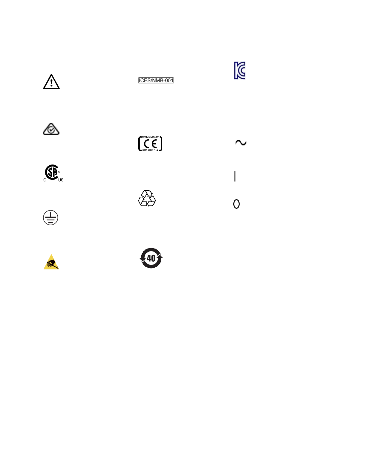
Indicates warning or caution. If you see this symbol
on a product, you must refer to the manuals for
specific Warning or Caution information to avoid
personal injury or damage to the product.
The RCM mark indicates that this product meets
EMS/Product Safety Requirements and may be
imported to Australia and New Zealand.
The CSA mark is a registered trademark of the CSA
International. This instrument complies with
Canada: CSA 22.2 No. 61010-1 -04.
Indicates that protective earthing ground is
incorporated in the power cord.
This symbol indicates that internal
circuits can be damaged by electrostatic discharge
(ESD), therefore, avoid applying static discharges
to the panel input connectors.
This mark indicates compliance with the Canadian
EMC regulations.
ISM 1-A
This text denotes the instrument is an Industrial
Scientific and Medical Group 1 Class A product.
CE Marking to state compliance within the
European Community: This product is in conformity
with the relevant European Directives: EMC
Directive 2004/108/EC and Low Voltage Directive
2006/95/EC.
China RoHS regulations include requirements
related to packaging, and require compliance to
China standard GB18455-2001. This symbol
indicates compliance with the China RoHS
regulations for paper/fiberboard packaging.
Indicates the time period during which no
hazardous or toxic substance elements are
expected to leak or deteriorate during normal use.
Forty years is the expected useful life of the
product.
The South Korean Class A EMC declaration (KC)
mark indicates that this product is Class A suitable
for professional use and is for use in
electromagnetic environments outside of the
home.
The KC mark includes the marking’s identifier code
that has up to 26 digits and follows this format:
KCC-VWX-YYY-ZZZZZZZZZZZZZ.
This symbol indicates that the instrument requires
alternating current (AC) input.
This symbol indicates that the power line switch is
in the ON position.
This symbol indicates that the power line switch is
in the OFF position.
Page 6
Environmental Information
This product complies with the WEEE Directive (2002/96/EC) marketing
requirements. The affixed label indicates that you must not discard this
electrical/electronic product in domestic household waste.
Product category: With reference to the equipment types in the WEEE Directive
Annexure I, this product is classed as a “Monitoring and Control instrumentation”
product.
Do not dispose in domestic household waste.
To return unwanted products, contact your local Keysight office, or see
http://about.keysight.com/en/companyinfo/environment/takeback.shtml for
more information.
Page 7

Contents
1 N4965A Getting Started Guide ............................................................................ 9
1.1 Introduction .............................................................................................. 9
1.2 Support .................................................................................................... 9
1.3 N4965A Multi-Channel BERT Controller Shipping Box Contents ............... 10
1.4 N4955A-P12 / N4955A-D12 / N4956A-E12 Shipping Box Contents ....... 10
1.5 N4956A-E12 Indicators Quick Reference ................................................. 11
1.6 Unpacking .............................................................................................. 12
1.7 Important Notes ...................................................................................... 12
1.8 Measurement Best Practices ................................................................... 12
1.9 General Specifications ............................................................................ 13
1.10 Safety and Regulatory ............................................................................. 14
1.11 N4965A Multi-Channel BERT Controller Installation................................. 15
1.12 N4955A-P12/N4955A-D12 Installation ................................................. 15
1.13 N4956A-E12 Installation ........................................................................ 18
1.14 Connector Care ....................................................................................... 19
1.15 Returning the N4965A to Keysight Technologies ...................................... 19
Multi-Channel BERT 12.5 Gb/s User Guide 7
Page 8

8 Multi-Channel BERT 12.5 Gb/s User Guide
Page 9

N4965A Getting Started Guide
1 N4965A Getting Started Guide
1.1 Introduction
Welcome to the Keysight Technologies N4965A multi-channel BERT
12.5 Gb/s getting started guide. This guide will help you identify the contents of the
shipping package, perform a quick functional check of the product, and guide you on
where to find more information and support for the N4965A.
1.2 Support
For more information on the operation and features of the N4965A please refer to the
N4965A Multi-Channel BERT 12.5 Gb/s User Guide on the CD or the following
product webpage:
http://www.keysight.com/find/N4965A
Technical Support information:
http://www.keysight.com/find/assist
Page 10
N4965A Getting Started Guide
1.3 N4965A Multi-Channel BERT Controller Shipping Box Contents
The N4965A is shipped in a protective box with all the accessories required for
operation. The shipping box contains:
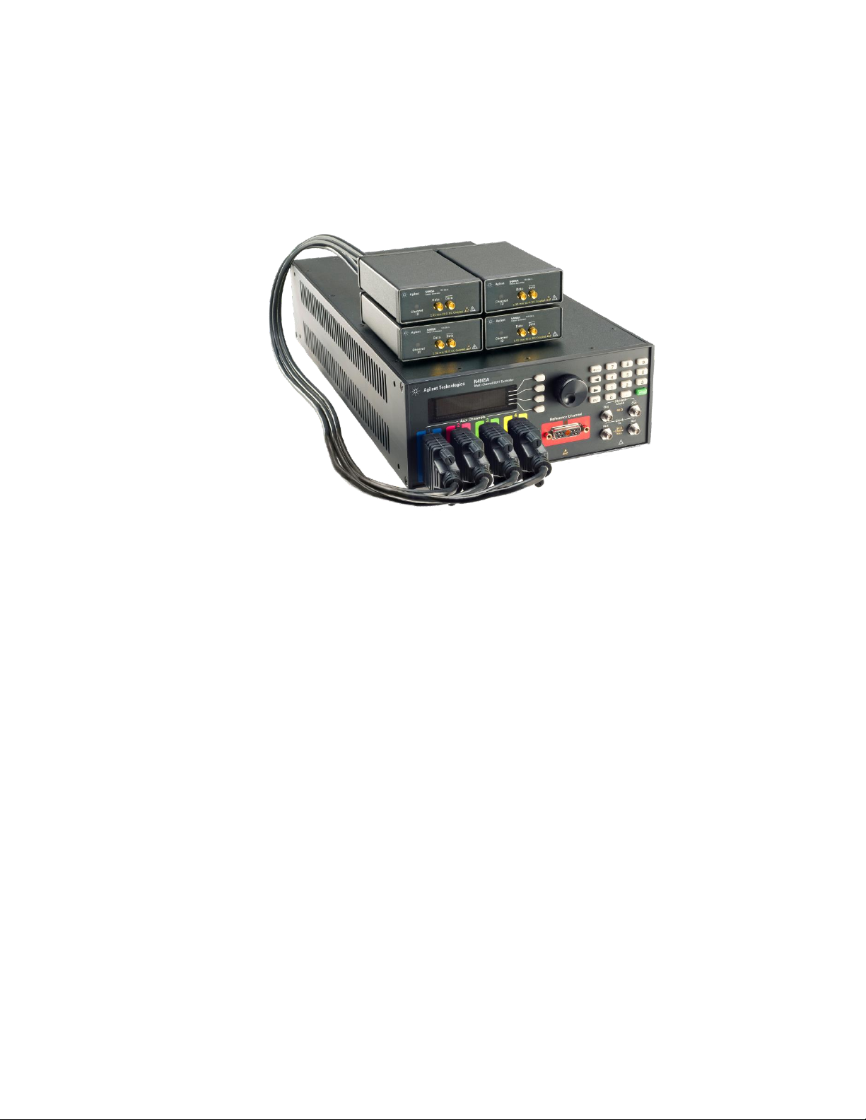
N4965A multi-channel BERT controller
Figure 1. N4965A multi-channel BERT controller
AC power cord
CD, which includes:
o N4965A multi-channel BERT 12.5 Gb/s data sheet
o N4965A multi-channel BERT 12.5 Gb/s getting started guide
o N4965A multi-channel BERT 12.5 Gb/s user guide
1.4 N4955A-P12 / N4955A-D12 / N4956A-E12 Shipping Box Contents
The N4955A-P12 / N4955A-D12 / N4956A-E12 is shipped in a protective box with
all the accessories required for operation. The shipping box contains:
Accessory kit, which includes the following for each N4955A-P12 / N4955A-D12
/ N4956A-E12:
o (Qty 2) 2.92 mm male-male cables
o (Qty 2) 2.92 mm male-female cables
o (Qty 1) 50 Ω 18 GHz 1 W SMA Male Terminations
Refer to the N4960-90030 N495xA through N498xA Connector Care Reference Guide
at www.keysight.com/find/N4955A.
10 Multi-Channel BERT 12.5 Gb/s User Guide
Page 11
1.5 N4956A-E12 Indicators Quick Reference
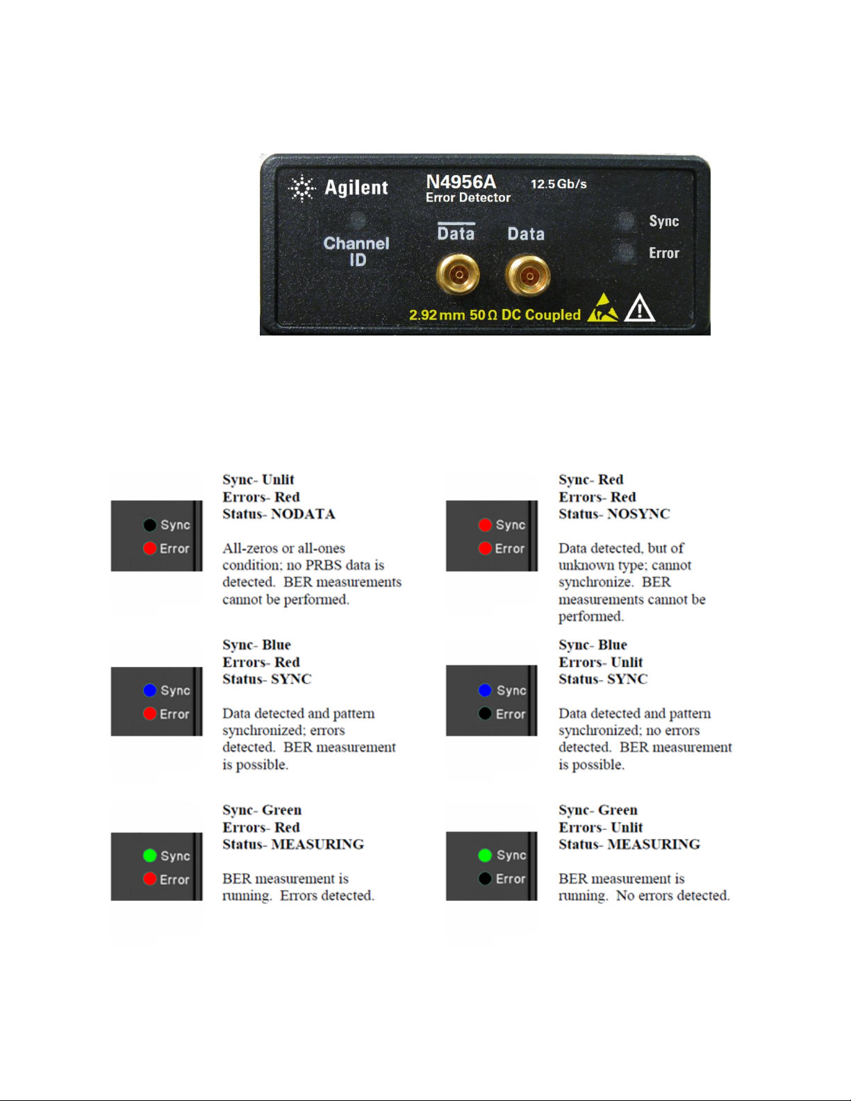
Figure 2. N4956A-E12 LED indicators
Three LED indicators are integrated into the N4956A-E12 front panel. These
indicators are used to communicate the current status of the N4956A-E12 error
detector. The combinations are shown below.
Multi-Channel BERT 12.5 Gb/s User Guide 11
Page 12

N4965A Getting Started Guide
Excessive mating of low quality SMA components to 2.92 mm female
receptacles may degrade the 2.92 mm female receptacle.
1.6 Unpacking
Carefully remove the instrument from the case in an ESD-safe environment.
1.7 Important Notes
Use ESD protection at all times when using the instrument.
Review min/max specifications before applying input signals.
Use high quality SMA-connectors on the SMA ports.
Leave dust covers on unused connectors.
Situate the instrument away from heat sources, do not block the fan, and do not
When using multiple remote heads, allow adequate space around heads for
Use 50 Ω terminations on all unused differential ports.
Use a 8 lbf-in (90 N-cm) torque wrench when attaching connectors.
block the exhaust vent (minimum of 8 cm/3 inches clearance).
cooling. If heads are stacked then additional cooling, e.g. using a fan, may be
required.
1.8 Measurement Best Practices
When using differential-mode connections, ensure the cables are phase
balanced for best performance.
Differential connectors may be used single-ended if unused outputs are
terminated in 50 Ω.
Use high quality cables and connector savers (or adaptors).
Keep cable lengths short and minimize the number of cable bends.
Use a 8 lb-in (90 N-cm) torque wrench when attaching connectors.
12 Multi-Channel BERT 12.5 Gb/s User Guide
Page 13
Parameter
Specification
Operating temperature
+10 C to +40 ºC
Storage temperature
–40 ºC to +70 ºC
Remote control interface
USB2.0 and IEEE-488 (GPIB)
Voltage
100 to 240 VAC auto ranging
Frequency
50/60 Hz nominal
Power consumption
170 Watts maximum
Current
1.8 A RMS maximum
Fuse
250 V 2 A (p/n 12260-002)
Always replace instrument fuse with one of the same type and rating.
EMC
CISPR Pub 11 Group 1, class A
AS/NZS CISPR 11
ICES/NMB-001
This ISM device complies with Canadian ICES-001.
Cet appareil ISM est conforme a la norme NMB-001 du Canada.
Safety
Complies with European Low Voltage Directive 2006/95/EC
IEC/EN 61010-1, 2nd Edition
Canada: CSA C22.2 No. 61010-1
USA: UL std no. 61010-1, 2nd Edition
Acoustic noise emission Geraeuschemission
LpA <70 dB LpA <70 dB
Operator position Am Arbeitsplatz
Normal position Normaler Betrieb
Per ISO 7779 Nach DIN 45635 t.19
Dimensions (Height, Width,
and Depth)
N4965A
100 mm (3.9 in) x 214 mm (8.4 in) x 425 mm (16.7 in)
N4955A-P12
33 mm (1.3 in) x 72 mm (2.8 in) x 130 mm (5.1 in)
N4955A-D12
33 mm (1.3 in) x 72 mm (2.8 in) x 130 mm (5.1 in)
N4956A-E12
33 mm (1.3 in) x 72 mm (2.8 in) x 130 mm (5.1 in)
1.9 General Specifications
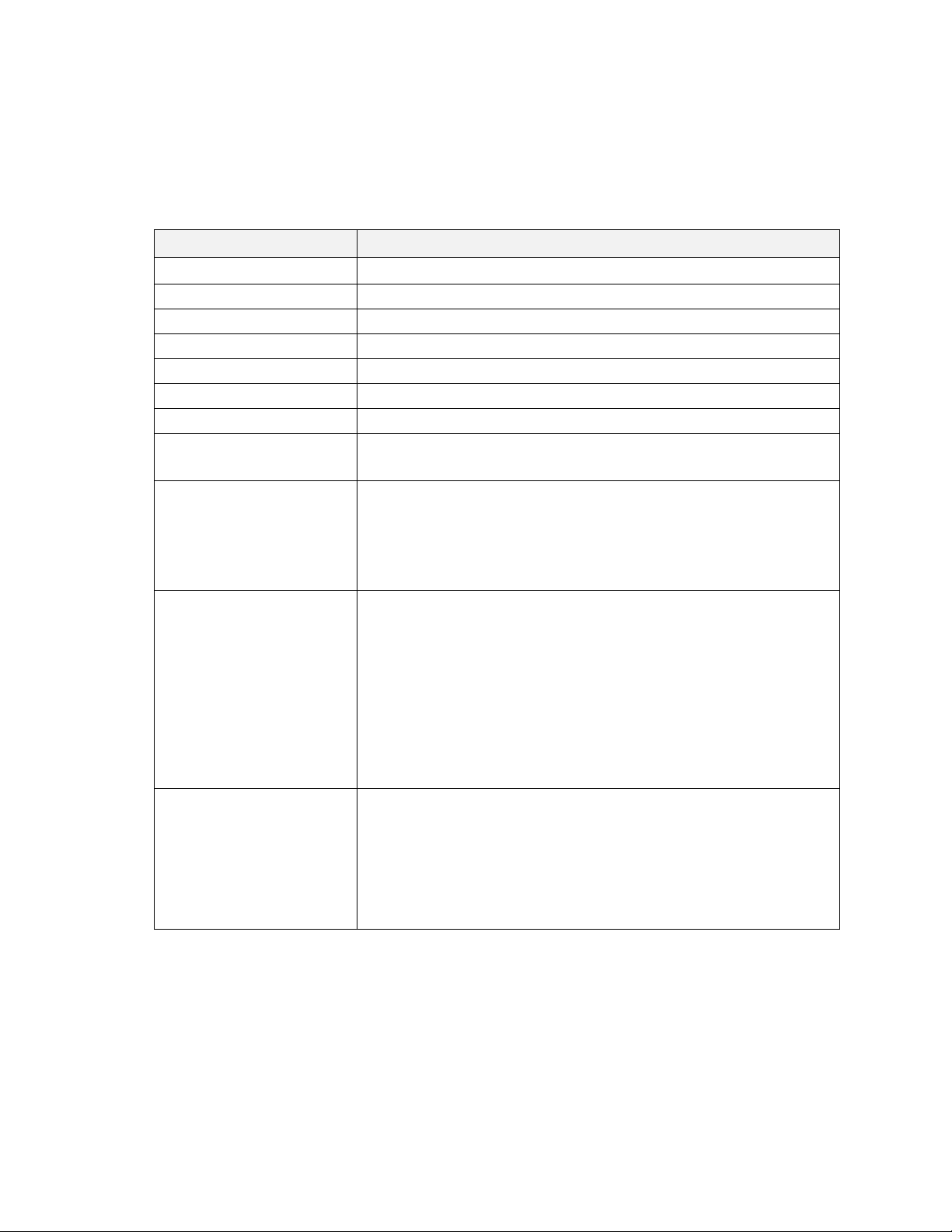
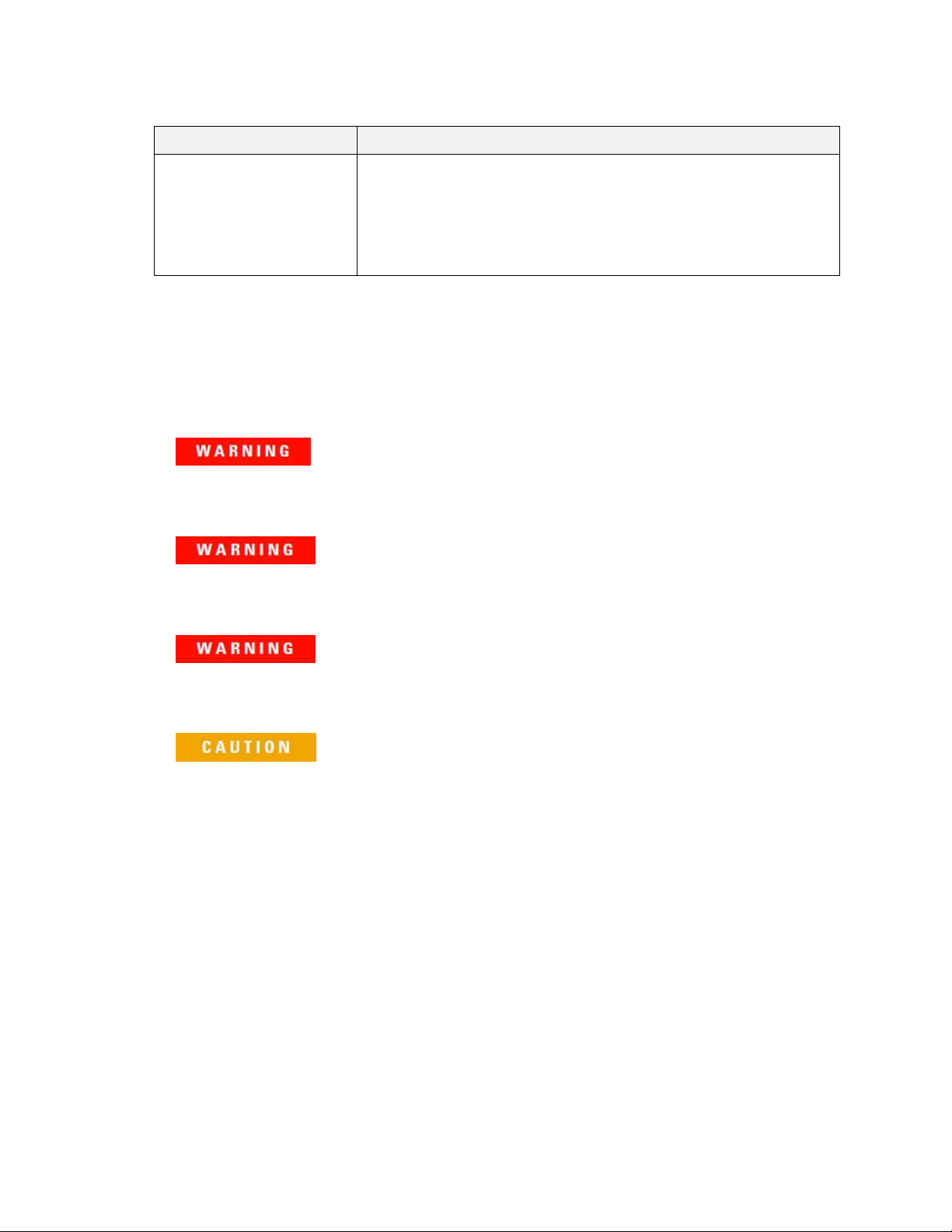
Before installing the system, review the specifications in Table 1.
Table 1. Specification considerations before installation
Multi-Channel BERT 12.5 Gb/s User Guide 13
Page 14
N4965A Getting Started Guide
Parameter
Specification
Weight N4965A
3.3 kg (7.1 lbs)
N4955A-P12
0.38 kg (13.4 oz)
N4955A-D12
0.38 kg (13.4 oz)
N4956A-E12
0.38 kg (13.4 oz)
Do not remove instrument covers. There are no user serviceable parts within.
Operation of the instrument in a manner not specified by Keysight Technologies
may result in personal injury or loss of life.
For continued protection against fire hazard, replace fuses, and or circuit
breakers only with same type and ratings. The use of other fuses, circuit breakers
or materials is prohibited.
To prevent electrical shock, disconnect the instrument from the AC Main before
cleaning. Use only a dry cloth or cloth slightly dampened with water to clean the
external case parts. Do not attempt to clean internally.
The Mains wiring and connectors shall be compatible with the connector used in
the premise electrical system. Failure, to ensure adequate earth grounding by
not using the correct components may cause product damage, and serious
injury.
1.10 Safety and Regulatory
This product has been designed and tested in accordance with accepted industry
standards, and has been supplied in a safe condition. The documentation contains
information and warnings that must be followed by the user to ensure safe operation
and to maintain the product in a safe condition.
14 Multi-Channel BERT 12.5 Gb/s User Guide
Page 15
If this product is not used as specified, the protection provided by the equipment
could be impaired. This product must be used in a normal condition (in which all
means for protection are intact) only.
1.11 N4965A Multi-Channel BERT Controller Installation
1. Install on a flat surface with unobstructed airflow to the back panel and right-
hand side of the N4965A.
2. Plug the AC power cord into the N4965A controller, rear panel power socket.
3. Plug the AC power cord into a suitable wall socket (100 to 240 V AC, 50/60
Hz).
1.12 N4955A-P12/N4955A-D12 Installation
1. Connect the N4955A-P12/N4955A-D12 PRBS Generator(s) to the N4965A
controller Channel 0.
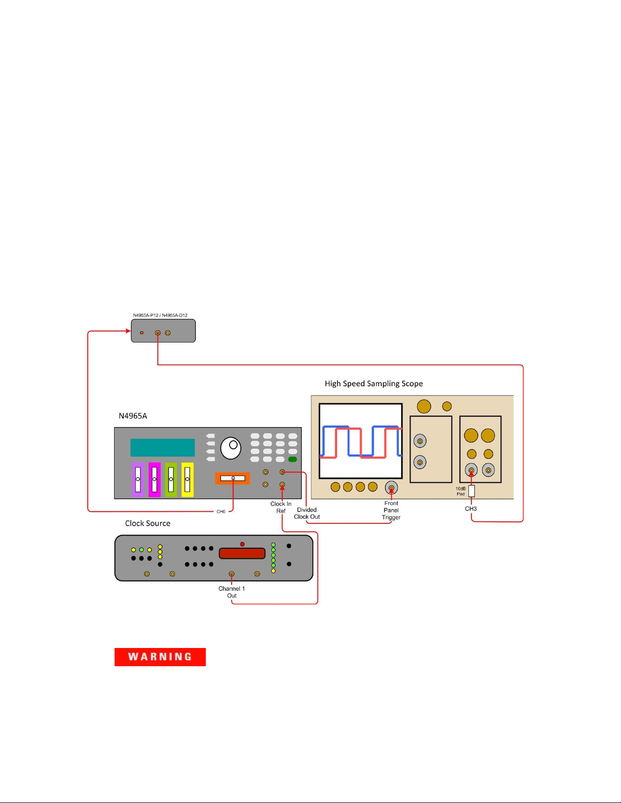
2. Connect the N4965A to a clock source and the N4955A-P12/N4955A-D12
(s) to a high speed sampling scope as shown in Figure 3. Tighten coax
connectors to 8 lb-in (90 N-cm) and use 50 Ω terminations on all unused
ports.
3. Turn on the N4965A.
Figure 3. PRBS generator setup
Multi-Channel BERT 12.5 Gb/s User Guide 15
Page 16
N4965A Getting Started Guide
Before switching on this instrument, make sure the supply voltage is in the
specified range.
This instrument has auto ranging line voltage input. Be sure the supply voltage is
within the specified range.
For purposes of this example setup, an Keysight 86100A Infinium DCA was
used. High-speed sampling scope setup option names may differ between
models.
4. Set up the clock source as follows:
Frequency: 10 GHz
Level: +3 dBm
Output: On
5. Set up the high speed sampling scope as follows:
Set the high speed sampling scope to Eye/Mask model.
Trigger Setup
Trigger Level: 0 V
Slope: Rising Edge
Trigger Bandwidth: Standard (DC-2.5 GHz)
Timebase Setup
Scale: 16.3 ps/div
Reference: center
Channel 3 Setup (data)
Attenuation: 10 dB (10 dB attenuator placed at the input)
Bandwidth: maximum
Display: On
Scale: 243 mV/Div
Offset: 0 V
6. If the STAT menu does not appear, press the softkey corresponding to the
STAT label until the STAT (Status) menu appears.
7. On the keypad, press the number 0 to view the STAT (Status) menu settings
for channel 0.
8. Position the arrow next to the Pat Out label on the N4965A then press the
softkey corresponding to the EDIT label.
16 Multi-Channel BERT 12.5 Gb/s User Guide
Page 17
9. Rotate the knob until the highlighted text shows ON then press the softkey
corresponding to the EXIT label to accept the change. This will turn on the
data output. The channel ID LED of the N4955A-P12/N4955A-D12 should
come on.
10. Position the arrow next to the Clk Output label on the N4965A then press the
softkey corresponding to the EDIT label.
11. Rotate the knob until the highlighted text shows ON then press the softkey
corresponding to the EXIT label to accept the change. This will turn on the
clock output.
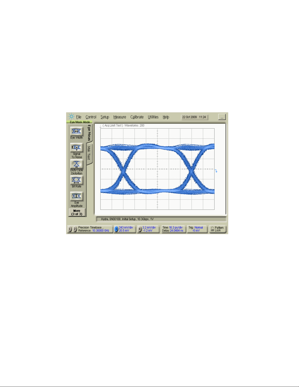
12. Verify that the waveform is similar to the one shown in Figure 4.
Figure 4. Installation setup waveform
Multi-Channel BERT 12.5 Gb/s User Guide 17
Page 18
N4965A Getting Started Guide
Data
Data
Data
Data
1.13 N4956A-E12 Installation
1. You will need a N4955A-P12 or N4955A-D12 PRBS generator head for this
installation test. Connect the PRBS generator to the reference channel
(Channel 0).
2. Connect the N4956A-E12 to channel 1.
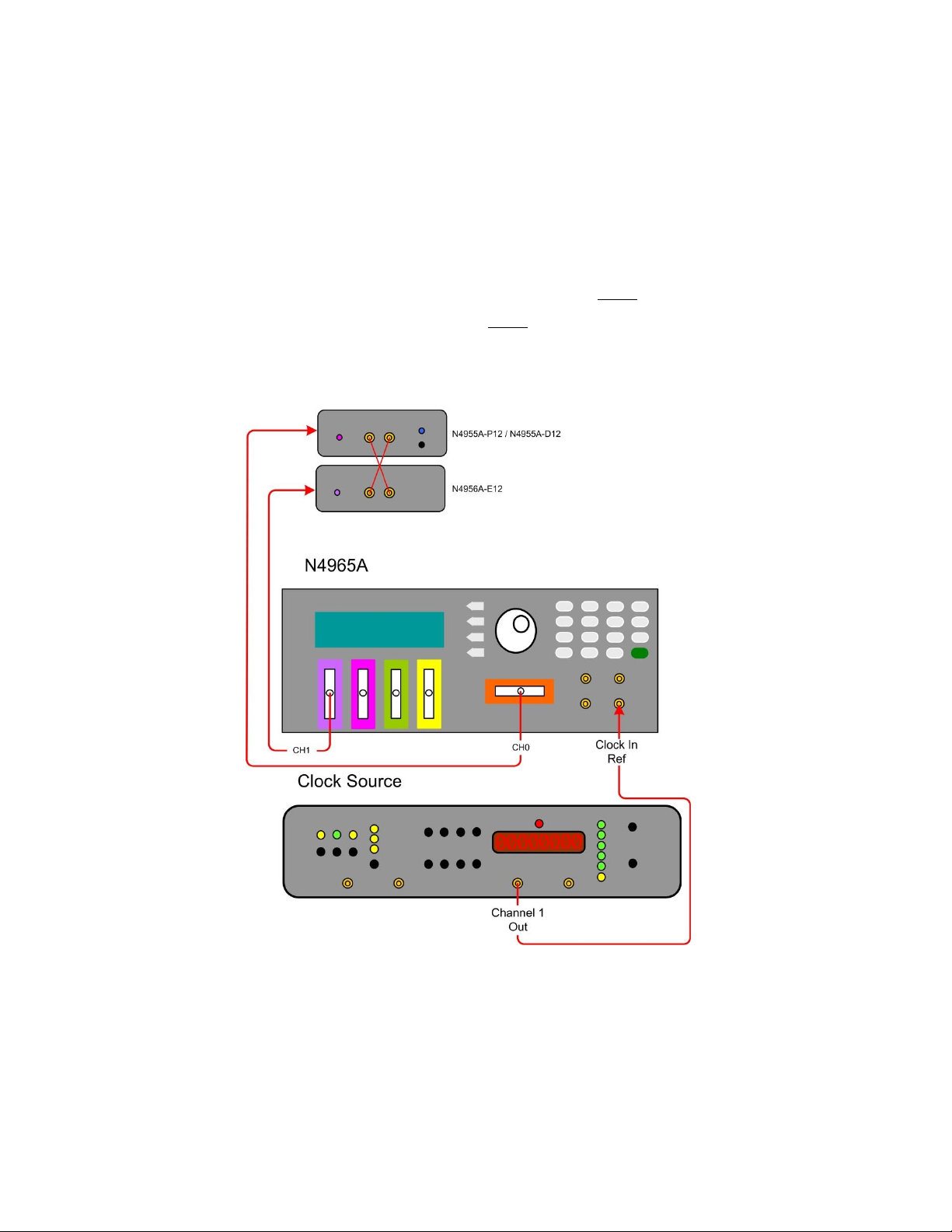
3. Connect the remote heads and clock source to the N4965A controller as
shown in Figure 5.
4. Using the supplied cables, connect
from the N4955A-P12/N4955A-
D12 to
P12/N4955A-D12 to
to 8 lb-in (90 N-cm).
on the N4956A-E12 and
from the N4955A-
on the N4956A-E12. Tighten coax connectors
Figure 5. N4956A-E12 installation setup
5. On the keypad, press the number 0 to view the STAT (Status) menu settings
for the PRBS generator connected to channel 0.
6. Position the arrow next to the Pat Out label on the N4965A then press the
softkey corresponding to the EDIT label.
7. Rotate the knob until the highlighted text shows ON then press the softkey
corresponding to the EXIT label to accept the change. This will turn on the
18 Multi-Channel BERT 12.5 Gb/s User Guide
Page 19

Excessive mating of low quality SMA connectors to 2.92 mm female connectors
may degrade the 2.92 mm female receptacle.
1.14 Connector Care
data output. The channel ID LED of the N4955A-P12/N4955A-D12 should
come on.
8. Set up the clock source as follows: Frequency 10 GHz, Output Level
0 dBm.
9. On the keypad, press the number 1 to view the STAT (Status) menu settings
for the N4956A-E12 connected to channel 1.
10. Position the arrow next to the Sync label on the N4965A then press the
softkey corresponding to the Align label. This will turn on the auto alignment.
11. Position the arrow next to the BER label on the N4965A then press the
softkey corresponding to the RUN label. MEAS 000 000 should appear
above BER and start counting. The BER and Errs should read 0.000e0.
The system features high-quality SMA and 2.92 mm connectors for the front panel
input and output connections. Connector damage will degrade signal fidelity.
Refer to the N4960-90030 N495xA through N498xA Connector Care Reference Guide
at www.keysight.com/find/N4955A.
Inspect the connectors for the following:
Worn or damaged threads
Scratches to mating surface
Burrs and loose metal particles
Ensure that female contacts are straight and aligned
Clean the connectors as described in the following procedure. Cleaning connectors
with alcohol shall only be done with the instruments power cord removed, and in a
well-ventilated area. Allow all residual alcohol moisture to evaporate, and the fumes
to dissipate prior to energizing the instrument.
1. Remove any loose particles using a low-pressure air source.
2. Moisten a lint-free swab with isopropyl alcohol. Do not saturate the swab.
3. Minimize the wicking of the alcohol into the connector structure.
4. Clean the mating plane surfaces and threads.
5. Allow alcohol to evaporate, and then use a low-pressure air source to blow
surfaces clean.
6. Make sure no particles or residue remains.
Inspect connector for damage.
1.15 Returning the N4965A to Keysight Technologies
If the N4965A fails system verification and you cannot correct the problem, return the
N4965A to Keysight Technologies for repair following the steps shown below.
Multi-Channel BERT 12.5 Gb/s User Guide 19
Page 20

N4965A Getting Started Guide
1. Record all symptoms.
2. Contact Keysight Technologies using the “Request an RMA” form at
http://www.keysight.com/find/assist.
3. Use the original packing material or similar packing material to ship the
N4965A to Keysight Technologies.
20 Multi-Channel BERT 12.5 Gb/s User Guide
Page 21

Page 22

This information is subject to change without notice.
© Keysight Technologies 2012, 2015
Edition 7, October 2015
www.keysight.com
 Loading...