

Page 1

Reference Guide
Keysight
Electronic Calibration Modules
This manual provides documentation for the following models:
RF 2-Port:
85091D, 85092D, 85093D, 85094D, 85096D, 85098D, 85099D
N7550A, N7551A, N7552A
RF 4-Port: N4431D
Microwave 2-Port:
N4696D, N7553A, N7554A, and N7555A
Microwave 4-Port: N4432D, and N4433D
This is the latest ECal modules Reference Guide.
For legacy ECal models, refer to the N4693-90001
Reference Guide:
https://www.keysight.com/us/en/assets/9018-03493/
reference-guides/9018-03493.pdf
N4690D, N4691D, N4692D, N4693D, N4694D,
Page 2

Notices
© Keysight Technologies, Inc.
2008-2022
No part of this manual may be
reproduced in any form or by any
means (including electronic storage
and retrieval or translation into a
foreign language) without prior
agreement and written consent from
Keysight Technologies, Inc. as
governed by United States and
international copyright laws.
Trademark Acknowledgments
Manual Part Number
N7550-90002
Edition
Edition 1, February 10, 2022
Printed in USA/Malaysia
Published by:
Keysight Technologies
1400 Fountaingrove Parkway
Santa Rosa, CA 95403
Warranty
THE MATERIAL CONTAINED IN THIS
DOCUMENT IS PROVIDED “AS IS,”
AND IS SUBJECT TO BEING
CHANGED, WITHOUT NOTICE, IN
FUTURE EDITIONS. FURTHER, TO
THE MAXIMUM EXTENT PERMITTED
BY APPLICABLE LAW, KEYSIGHT
DISCLAIMS ALL WARRANTIES,
EITHER EXPRESS OR IMPLIED WITH
REGARD TO THIS MANUAL AND
ANY INFORMATION CONTAINED
HEREIN, INCLUDING BUT NOT
LIMITED TO THE IMPLIED
WARRANTIES OF
MERCHANTABILITY AND FITNESS
FOR A PARTICULAR PURPOSE.
KEYSIGHT SHALL NOT BE LIABLE
FOR ERRORS OR FOR INCIDENTAL
OR CONSEQUENTIAL DAMAGES IN
CONNECTION WITH THE
FURNISHING, USE, OR
PERFORMANCE OF THIS
DOCUMENT OR ANY INFORMATION
CONTAINED HEREIN. SHOULD
KEYSIGHT AND THE USER HAVE A
SEPARATE WRITTEN AGREEMENT
WITH WARRANTY TERMS
COVERING THE MATERIAL IN THIS
DOCUMENT THAT CONFLICT WITH
THESE TERMS, THE WARRANTY
TERMS IN THE SEPARATE
AGREEMENT WILL CONTROL.
Technology Licenses
The hardware and/or software
described in this document are
furnished under a license and
may be used or copied only in
accordance with the terms of
such license.
U.S. Government Rights
The Software is “commercial
computer software,” as defined
by Federal Acquisition Regulation
(“FAR”) 2.101. Pursuant to FAR
12.212 and 27.405-3 and
Department of Defense FAR
Supplement (“DFARS”) 227.7202,
the U.S. government acquires
commercial computer software
under the same terms by which
the software is customarily
provided to the public.
Accordingly, Keysight provides
the Software to U.S. government
customers under its standard
commercial license, which is
embodied in its End User License
Agreement (EULA), a copy of
which can be found at
http://www.keysight.com/find/s
weula The license set forth in the
EULA represents the exclusive
authority by which the U.S.
government may use, modify,
distribute, or disclose the
Software. The EULA and the
license set forth therein, does not
require or permit, among other
things, that Keysight: (1) Furnish
technical information related to
commercial computer software
or commercial computer
software documentation that is
not customarily provided to the
public; or (2) Relinquish to, or
otherwise provide, the
government rights in excess of
these rights customarily provided
to the public to use, modify,
reproduce, release, perform,
display, or disclose commercial
computer software or
commercial computer software
documentation. No additional
government requirements
beyond those set forth in the
EULA shall apply, except to the
extent that those terms, rights, or
licenses are explicitly required
from all providers of commercial
computer software pursuant to
the FAR and the DFARS and are
set forth specifically in writing
elsewhere in the EULA. Keysight
shall be under no obligation to
update, revise or otherwise
modify the Software. With
respect to any technical data as
defined by FAR 2.101, pursuant
to FAR 12.211 and 27.404.2 and
DFARS 227.7102, the U.S.
government acquires no greater
than Limited Rights as defined in
FAR 27.401 or DFAR 227.7103-5
(c), as applicable in any technical
data.
Safety Notices
A CAUTION notice denotes a hazard.
It calls attention to an operating
procedure, practice, or the like that,
if not correctly performed or adhered
to, could result in damage to the
product or loss of important data. Do
not proceed beyond a CAUTION
notice until the indicated conditions
are fully understood and met.
A WARNING notice denotes a
hazard. It calls attention to an
operating procedure, practice, or the
like that, if not correctly performed or
adhered to, could result in personal
injury or death. Do not proceed
beyond a WARNING notice until the
indicated conditions are fully
understood and met.
Page 3

Where to Find the Latest Information
Documentation is updated periodically. For the latest information about these products, including instrument
software upgrades, application information, and product information, browse to one of the following URLs,
according to the name of your product:
http://www.keysight.com/find/
To receive the latest updates by email, subscribe to Keysight Email Updates at the following URL:
http://www.keysight.com/find/MyKeysight
Information on preventing instrument damage can be found at:
www.keysight.com/find/PreventingInstrumentRepair
Is your product software up-to-date?
Periodically, Keysight releases software updates to fix known defects and incorporate product enhancements.
To search for software updates for your product, go to the Keysight Technical Support website at:
http://www.keysight.com/find/techsupport
3
Page 4

4
Page 5

Contents
1. General Information
Manual Overview . . . . . . . . . . . . . . . . . . . . . . . . . . . . . . . . . . . . . . . . . . . . . . . . . . . . . . . . . . 1-1
Prerequisite Knowledge . . . . . . . . . . . . . . . . . . . . . . . . . . . . . . . . . . . . . . . . . . . . . . . . . . 1-1
Clarifying the Terminology of a Connector Interface. . . . . . . . . . . . . . . . . . . . . . . . . . . . 1-1
Accuracy of Electronic Calibration versus Mechanical Calibration. . . . . . . . . . . . . . . . . 1-2
When to Calibrate. . . . . . . . . . . . . . . . . . . . . . . . . . . . . . . . . . . . . . . . . . . . . . . . . . . . . . . . . . 1-3
Models and Options . . . . . . . . . . . . . . . . . . . . . . . . . . . . . . . . . . . . . . . . . . . . . . . . . . . . . . . . 1-4
8509xD Modules (RF Two-Port) . . . . . . . . . . . . . . . . . . . . . . . . . . . . . . . . . . . . . . . . . . . 1-4
N755xA Modules (RF Two-Port) . . . . . . . . . . . . . . . . . . . . . . . . . . . . . . . . . . . . . . . . . . . 1-9
N4431D Modules (RF Four-Port) . . . . . . . . . . . . . . . . . . . . . . . . . . . . . . . . . . . . . . . . . 1-11
N469xD Modules (Microwave Two-Port) . . . . . . . . . . . . . . . . . . . . . . . . . . . . . . . . . . . 1-14
N4432D and N4433D Modules (Microwave Four-Port). . . . . . . . . . . . . . . . . . . . . . . . . 1-18
Compatible Network Analyzers . . . . . . . . . . . . . . . . . . . . . . . . . . . . . . . . . . . . . . . . . . . . . . 1-21
Service and Recertification. . . . . . . . . . . . . . . . . . . . . . . . . . . . . . . . . . . . . . . . . . . . . . . . . . 1-29
Contacting Keysight . . . . . . . . . . . . . . . . . . . . . . . . . . . . . . . . . . . . . . . . . . . . . . . . . . . . 1-29
Returning Devices to Keysight. . . . . . . . . . . . . . . . . . . . . . . . . . . . . . . . . . . . . . . . . . . . 1-29
Recertification of ECal Modules. . . . . . . . . . . . . . . . . . . . . . . . . . . . . . . . . . . . . . . . . . . 1-30
Safety and Regulatory Information . . . . . . . . . . . . . . . . . . . . . . . . . . . . . . . . . . . . . . . . . . . 1-32
Safety Notices . . . . . . . . . . . . . . . . . . . . . . . . . . . . . . . . . . . . . . . . . . . . . . . . . . . . . . . . 1-33
Instrument Markings . . . . . . . . . . . . . . . . . . . . . . . . . . . . . . . . . . . . . . . . . . . . . . . . . . . 1-33
Compliance Notices . . . . . . . . . . . . . . . . . . . . . . . . . . . . . . . . . . . . . . . . . . . . . . . . . . . 1-34
Contents
2. Preparing ECal for Use
Inspecting the ECal Kit . . . . . . . . . . . . . . . . . . . . . . . . . . . . . . . . . . . . . . . . . . . . . . . . . . . . . . 2-1
Inspect the Kit Contents. . . . . . . . . . . . . . . . . . . . . . . . . . . . . . . . . . . . . . . . . . . . . . . . . . 2-1
Locate the Serial Number . . . . . . . . . . . . . . . . . . . . . . . . . . . . . . . . . . . . . . . . . . . . . . . . 2-1
Record the Serial Number . . . . . . . . . . . . . . . . . . . . . . . . . . . . . . . . . . . . . . . . . . . . . . . . 2-3
Verify Electrical Performance . . . . . . . . . . . . . . . . . . . . . . . . . . . . . . . . . . . . . . . . . . . . . . 2-3
Equipment Required but Not Supplied . . . . . . . . . . . . . . . . . . . . . . . . . . . . . . . . . . . . . . 2-3
Kit Contents . . . . . . . . . . . . . . . . . . . . . . . . . . . . . . . . . . . . . . . . . . . . . . . . . . . . . . . . . . . . . . 2-4
8509xD Series Kit Contents . . . . . . . . . . . . . . . . . . . . . . . . . . . . . . . . . . . . . . . . . . . . . . . 2-4
N755xA Series Kit Contents. . . . . . . . . . . . . . . . . . . . . . . . . . . . . . . . . . . . . . . . . . . . . . 2-11
N4431D Series Kit Contents . . . . . . . . . . . . . . . . . . . . . . . . . . . . . . . . . . . . . . . . . . . . . 2-12
N469xD Seres Kit Contents . . . . . . . . . . . . . . . . . . . . . . . . . . . . . . . . . . . . . . . . . . . . . . 2-14
N4432D and N4433D Series Kit Contents. . . . . . . . . . . . . . . . . . . . . . . . . . . . . . . . . . . 2-15
Options . . . . . . . . . . . . . . . . . . . . . . . . . . . . . . . . . . . . . . . . . . . . . . . . . . . . . . . . . . . . . . . . . 2-17
8509xD Options . . . . . . . . . . . . . . . . . . . . . . . . . . . . . . . . . . . . . . . . . . . . . . . . . . . . . . . 2-17
N755xA Options . . . . . . . . . . . . . . . . . . . . . . . . . . . . . . . . . . . . . . . . . . . . . . . . . . . . . . . 2-17
Electronic Calibration Modules Reference Guide 5
Page 6

Contents
N4431D Options . . . . . . . . . . . . . . . . . . . . . . . . . . . . . . . . . . . . . . . . . . . . . . . . . . . . . . . 2-17
N469xD Options . . . . . . . . . . . . . . . . . . . . . . . . . . . . . . . . . . . . . . . . . . . . . . . . . . . . . . .2-17
N4432D Options . . . . . . . . . . . . . . . . . . . . . . . . . . . . . . . . . . . . . . . . . . . . . . . . . . . . . . . 2-17
N4433D Options . . . . . . . . . . . . . . . . . . . . . . . . . . . . . . . . . . . . . . . . . . . . . . . . . . . . . . . 2-18
Operating and Safety Precautions . . . . . . . . . . . . . . . . . . . . . . . . . . . . . . . . . . . . . . . . . . . . 2-18
ESD Damage . . . . . . . . . . . . . . . . . . . . . . . . . . . . . . . . . . . . . . . . . . . . . . . . . . . . . . . . . . 2-18
Connector Care . . . . . . . . . . . . . . . . . . . . . . . . . . . . . . . . . . . . . . . . . . . . . . . . . . . . . . . .2-18
Input Power Level . . . . . . . . . . . . . . . . . . . . . . . . . . . . . . . . . . . . . . . . . . . . . . . . . . . . . .2-20
Operating Temperature . . . . . . . . . . . . . . . . . . . . . . . . . . . . . . . . . . . . . . . . . . . . . . . . . . 2-20
3. Operating ECal Module
Setting Up a Calibration . . . . . . . . . . . . . . . . . . . . . . . . . . . . . . . . . . . . . . . . . . . . . . . . . . . . . 3-1
Understanding the ECal LEDs. . . . . . . . . . . . . . . . . . . . . . . . . . . . . . . . . . . . . . . . . . . . . . 3-1
Required Procedure for All Calibrations (PNA and PXIe) . . . . . . . . . . . . . . . . . . . . . . . . . 3-3
Required Procedure for All Calibrations (ENA E5061B, E5063A, E5071C, and E5072A) 3-3
Required Procedure for All Calibrations (FieldFox). . . . . . . . . . . . . . . . . . . . . . . . . . . . . . 3-4
Calibration Types Available . . . . . . . . . . . . . . . . . . . . . . . . . . . . . . . . . . . . . . . . . . . . . . . . 3-6
When to Correct for Isolation . . . . . . . . . . . . . . . . . . . . . . . . . . . . . . . . . . . . . . . . . . . . . . 3-7
Calibration Methods for Non-Insertable Devices . . . . . . . . . . . . . . . . . . . . . . . . . . . . . . . 3-8
Finding More Information on Performing a Calibration . . . . . . . . . . . . . . . . . . . . . . . . . . . . 3-10
Validating a Calibration . . . . . . . . . . . . . . . . . . . . . . . . . . . . . . . . . . . . . . . . . . . . . . . . . . . .3-11
ECal Confidence Check – Basic Validation of the Calibration . . . . . . . . . . . . . . . . . . . . 3-11
System Verification Procedure – Traceable Accuracy Validation of the Calibrated
Measurement System . . . . . . . . . . . . . . . . . . . . . . . . . . . . . . . . . . . . . . . . . . . . . . . . . . .3-12
ECal Troubleshooting. . . . . . . . . . . . . . . . . . . . . . . . . . . . . . . . . . . . . . . . . . . . . . . . . . . . . . .3-14
4. Use, Maintenance, and Care of the Devices
Electrostatic Discharge . . . . . . . . . . . . . . . . . . . . . . . . . . . . . . . . . . . . . . . . . . . . . . . . . . . . . . 4-1
Visual Inspection . . . . . . . . . . . . . . . . . . . . . . . . . . . . . . . . . . . . . . . . . . . . . . . . . . . . . . . . . . . 4-3
Look for Obvious Defects and Damage First . . . . . . . . . . . . . . . . . . . . . . . . . . . . . . . . . . 4-3
Inspect the Mating Plane Surfaces . . . . . . . . . . . . . . . . . . . . . . . . . . . . . . . . . . . . . . . . . . 4-3
Inspect Female Connectors. . . . . . . . . . . . . . . . . . . . . . . . . . . . . . . . . . . . . . . . . . . . . . . . . . . 4-5
Cleaning Connectors . . . . . . . . . . . . . . . . . . . . . . . . . . . . . . . . . . . . . . . . . . . . . . . . . . . . . . . . 4-6
Cleaning Coax Connectors . . . . . . . . . . . . . . . . . . . . . . . . . . . . . . . . . . . . . . . . . . . . . . . .4-6
Cleaning 7 mm Connectors. . . . . . . . . . . . . . . . . . . . . . . . . . . . . . . . . . . . . . . . . . . . . . . . 4-7
Gaging Connectors . . . . . . . . . . . . . . . . . . . . . . . . . . . . . . . . . . . . . . . . . . . . . . . . . . . . . . . . . 4-9
Connector Gage Accuracy . . . . . . . . . . . . . . . . . . . . . . . . . . . . . . . . . . . . . . . . . . . . . . . . 4-9
When to Gage Connectors . . . . . . . . . . . . . . . . . . . . . . . . . . . . . . . . . . . . . . . . . . . . . . . 4-10
Recognizing Gage Types . . . . . . . . . . . . . . . . . . . . . . . . . . . . . . . . . . . . . . . . . . . . . . . . . 4-10
Reading the Connector Gage . . . . . . . . . . . . . . . . . . . . . . . . . . . . . . . . . . . . . . . . . . . . . 4-10
Gaging Procedures . . . . . . . . . . . . . . . . . . . . . . . . . . . . . . . . . . . . . . . . . . . . . . . . . . . . . 4-14
6 Electronic Calibration Modules Reference Guide
Page 7

Making Connections. . . . . . . . . . . . . . . . . . . . . . . . . . . . . . . . . . . . . . . . . . . . . . . . . . . . . . . 4-17
1.85 mm, 3.5 mm, 2.4 mm, 2.92 mm, and Type-N Devices . . . . . . . . . . . . . . . . . . . . . 4-17
7 mm Devices . . . . . . . . . . . . . . . . . . . . . . . . . . . . . . . . . . . . . . . . . . . . . . . . . . . . . . . . . 4-17
Final Connection Using a Torque Wrench . . . . . . . . . . . . . . . . . . . . . . . . . . . . . . . . . . . 4-18
Separating Connections. . . . . . . . . . . . . . . . . . . . . . . . . . . . . . . . . . . . . . . . . . . . . . . . . 4-21
Handling and Storage . . . . . . . . . . . . . . . . . . . . . . . . . . . . . . . . . . . . . . . . . . . . . . . . . . . . . 4-22
ECal Kit Storage Box (Option 150) – (N755xA Only) . . . . . . . . . . . . . . . . . . . . . . . . . . . . . . 4-23
5. Specifications and Characteristics
Specifications: Terminology and Definitions . . . . . . . . . . . . . . . . . . . . . . . . . . . . . . . . . . . . . 5-1
Environmental Specifications. . . . . . . . . . . . . . . . . . . . . . . . . . . . . . . . . . . . . . . . . . . . . . . . . 5-2
Operating Temperature and Accuracy Enhancement . . . . . . . . . . . . . . . . . . . . . . . . . . . 5-2
Barometric Pressure and Relative Humidity . . . . . . . . . . . . . . . . . . . . . . . . . . . . . . . . . . 5-3
Electrical Specifications . . . . . . . . . . . . . . . . . . . . . . . . . . . . . . . . . . . . . . . . . . . . . . . . . . . . . 5-4
8509xD Series. . . . . . . . . . . . . . . . . . . . . . . . . . . . . . . . . . . . . . . . . . . . . . . . . . . . . . . . . . 5-4
N755xA Series . . . . . . . . . . . . . . . . . . . . . . . . . . . . . . . . . . . . . . . . . . . . . . . . . . . . . . . . . 5-7
N4431D (3.5 mm). . . . . . . . . . . . . . . . . . . . . . . . . . . . . . . . . . . . . . . . . . . . . . . . . . . . . . . 5-8
N4431D (Type-N 50 Ω) . . . . . . . . . . . . . . . . . . . . . . . . . . . . . . . . . . . . . . . . . . . . . . . . . . 5-8
N4431D (7-16) . . . . . . . . . . . . . . . . . . . . . . . . . . . . . . . . . . . . . . . . . . . . . . . . . . . . . . . . . 5-9
N4431D (4.3-10) . . . . . . . . . . . . . . . . . . . . . . . . . . . . . . . . . . . . . . . . . . . . . . . . . . . . . . . 5-9
N4432D (Type-N 50 Ω) . . . . . . . . . . . . . . . . . . . . . . . . . . . . . . . . . . . . . . . . . . . . . . . . . 5-10
N4433D (3.5 mm). . . . . . . . . . . . . . . . . . . . . . . . . . . . . . . . . . . . . . . . . . . . . . . . . . . . . . 5-10
N469xD Series . . . . . . . . . . . . . . . . . . . . . . . . . . . . . . . . . . . . . . . . . . . . . . . . . . . . . . . . 5-11
Contents
Characteristic Performance . . . . . . . . . . . . . . . . . . . . . . . . . . . . . . . . . . . . . . . . . . . . . . . . . 5-14
N755xA Series . . . . . . . . . . . . . . . . . . . . . . . . . . . . . . . . . . . . . . . . . . . . . . . . . . . . . . . . 5-14
N4431D (3.5 mm). . . . . . . . . . . . . . . . . . . . . . . . . . . . . . . . . . . . . . . . . . . . . . . . . . . . . . 5-15
N4431D (4.3-10) . . . . . . . . . . . . . . . . . . . . . . . . . . . . . . . . . . . . . . . . . . . . . . . . . . . . . . 5-15
N4431D (7-16) . . . . . . . . . . . . . . . . . . . . . . . . . . . . . . . . . . . . . . . . . . . . . . . . . . . . . . . . 5-16
N4431D (Type-N 50 Ω) . . . . . . . . . . . . . . . . . . . . . . . . . . . . . . . . . . . . . . . . . . . . . . . . . 5-16
N4432D (Type-N 50 Ω – Microwave). . . . . . . . . . . . . . . . . . . . . . . . . . . . . . . . . . . . . . . 5-17
N4433D (3.5 mm – Microwave) . . . . . . . . . . . . . . . . . . . . . . . . . . . . . . . . . . . . . . . . . . . 5-17
N469xD Series . . . . . . . . . . . . . . . . . . . . . . . . . . . . . . . . . . . . . . . . . . . . . . . . . . . . . . . . 5-18
Mechanical Characteristics . . . . . . . . . . . . . . . . . . . . . . . . . . . . . . . . . . . . . . . . . . . . . . . . . 5-21
Pin Depth . . . . . . . . . . . . . . . . . . . . . . . . . . . . . . . . . . . . . . . . . . . . . . . . . . . . . . . . . . . . 5-21
Type-N Characteristics. . . . . . . . . . . . . . . . . . . . . . . . . . . . . . . . . . . . . . . . . . . . . . . . . . 5-23
Typical Pin Depth Values . . . . . . . . . . . . . . . . . . . . . . . . . . . . . . . . . . . . . . . . . . . . . . . . . . . 5-26
Supplemental Mechanical Characteristics . . . . . . . . . . . . . . . . . . . . . . . . . . . . . . . . . . . . . 5-30
Mechanical Dimensions of the Modules . . . . . . . . . . . . . . . . . . . . . . . . . . . . . . . . . . . . 5-31
Measurement Uncertainty Calculator . . . . . . . . . . . . . . . . . . . . . . . . . . . . . . . . . . . . . . . . . 5-49
Download the Vector Network Analyzer Uncertainty Calculator . . . . . . . . . . . . . . . . . 5-49
Electronic Calibration Modules Reference Guide 7
Page 8

Contents
6. Replaceable Parts
Description of This Chapter. . . . . . . . . . . . . . . . . . . . . . . . . . . . . . . . . . . . . . . . . . . . . . . . . . .6-1
Type-F (75 ohm) Modules and Accessories . . . . . . . . . . . . . . . . . . . . . . . . . . . . . . . . . . . . . . 6-2
Type-N (50 ohm) Modules and Accessories . . . . . . . . . . . . . . . . . . . . . . . . . . . . . . . . . . . . . . 6-3
Type-N (75 ohm) Modules and Accessories . . . . . . . . . . . . . . . . . . . . . . . . . . . . . . . . . . . . . . 6-4
1.85 mm Modules and Accessories. . . . . . . . . . . . . . . . . . . . . . . . . . . . . . . . . . . . . . . . . . . . . 6-5
2.4 mm Modules and Accessories. . . . . . . . . . . . . . . . . . . . . . . . . . . . . . . . . . . . . . . . . . . . . . 6-6
2.92 mm Modules and Accessories. . . . . . . . . . . . . . . . . . . . . . . . . . . . . . . . . . . . . . . . . . . . . 6-7
3.5 mm Modules and Accessories. . . . . . . . . . . . . . . . . . . . . . . . . . . . . . . . . . . . . . . . . . . . . . 6-8
4.3-10 Modules and Accessories . . . . . . . . . . . . . . . . . . . . . . . . . . . . . . . . . . . . . . . . . . . . . . 6-9
7 mm Modules and Accessories . . . . . . . . . . . . . . . . . . . . . . . . . . . . . . . . . . . . . . . . . . . . . . 6-10
7-16 Modules and Accessories . . . . . . . . . . . . . . . . . . . . . . . . . . . . . . . . . . . . . . . . . . . . . . . 6-11
Other ECal Accessories . . . . . . . . . . . . . . . . . . . . . . . . . . . . . . . . . . . . . . . . . . . . . . . . . . . . 6-12
8 Electronic Calibration Modules Reference Guide
Page 9

Keysight Electronic Calibration Modules
RF/Microwave Two Port
Reference Guide
1 General Information
Manual Overview
The purpose of this manual is to help you use your Electronic Calibration (ECal)
module confidently and effectively. ECal is a precision, single-connection
calibration technique which uses fully traceable and verifiable electronic
standards. Each module has unique S-parameter data that is stored in the
module's memory. During calibration, ECal uses this data to calculate the error
terms for your network analyzer.
This manual provides instructions for operating and maintaining your ECal
module. Also included are mechanical specifications and replaceable parts
available for each model.
The 85091/2/3/4/6/8/9D series provide two-port calibration solutions with
operating frequencies starting as low as DC and ending as high as 9 GHz. The
N4690/1/2/3/4/6D series provide two-port calibration solutions with
operating frequencies starting as low as DC and ending as high as 67 GHz.
and N7550/1/2/3/4/5A series provide two-port calibration solutions with
operating frequencies starting as low as DC and ending as high as 26.5 GHz.
The N4431/2/3D series provide four-port calibration solutions with operating
frequencies starting as low as DC and ending as high as 26.5 GHz.
Prerequisite Knowledge
This manual assumes you are trained in proper connector care. Because an
accurate calibration depends on the integrity and cleanliness of the connector
interface, a damaged connector will invalidate the calibration achieved with
that module. Refer to the “Connector Care” on page 2-18.
Clarifying the Terminology of a Connector Interface
In this manual, adapters, ECal modules, and gage masters are referred to by
way of their interface connector. For example:
— A female adapter has a female interface.
— A male adapter has a male interface.
A connector gage is referred to by way of the connector it measures. For
example:
— A male connector gage has a female interface so it can measure male
devices.
1- 1
Page 10

1-
General Information
Manual Overview
— A female connector gage has a male interface so it can measure female
devices.
Accuracy of Electronic Calibration versus Mechanical Calibration
N755xA ECals can be used for S-parameter measurement calibrations. The
residual measurement uncertainty makes them unsuitable for advanced
applications, such as load pull, noise figure, etcetera.
As the number of DUT test ports increases, the required number of calibration
measurements also increases. This boosts the probability of bad connections
and bad calibrations when mechanical calibration standards are used rather
than ECal. Also, test port cable repeatability and stability errors are amplified
by the increased number of connections and disconnections. To perform an
SOLT 4-port calibration, a minimum of twelve 1-port standards and three
2-port (thru) standards are measured, requiring a total of eighteen
connections. The same calibration using a 2-port ECal module (N755xA and
N469xD) requires only four connections.
Ignoring connection related errors, the following table compares the accuracy
of ECal versus mechanical calibration in various calibration options.
Mechanical Calibration Type ECal Thru Type Measurement ECal Mechanical
1-Port, calibration constant (not
data-based) SOL
1-Port, short, open, sliding load NA Reflection +
1-Port, data-based, expanded NA Reflection +
2-Port TRL All types Reflection
≥2-Port, calibration constant SOL, flush
a
thru
≥2-Port, calibration constant SOL,
unknown thru
NA Reflection ++
Transmission
Characterized Reflection
Transmission
Internal unknown Reflection
Transmission
External flush
Characterized Reflection
a
Reflection
Transmission
Transmission
++ ++
++
++
++ ++
++
++
Calibration
Internal unknown Reflection
Transmission
1-2 Electronic Calibration Modules Reference Guide
++
=
=
Page 11

General Information
When to Calibrate
Mechanical Calibration Type ECal Thru Type Measurement ECal Mechanical
Calibration
≥2-Port, data-based, expanded, flush
a
thru
≥2-Port, data-based, expanded,
unknown thru
++ better; + slightly better; = same
a. Flush thru should NOT be used when the test port connectors are not the same type as the calibration standards. SMA and
3.5 mm connectors are mateable but are NOT the same type.
Characterized Reflection
Transmission
Internal unknown Reflection
Transmission
External flush
Characterized Reflection
Internal
unknown
a
Reflection
Transmission
Transmission
Reflection
Transmission
When to Calibrate
A network analyzer calibration remains valid as long as the changes in the
systematic error are insignificant. This means that changes to the uncorrected
leakages (directivity and isolation), mismatches (source match and load
match), and frequency response of the system are small (<10%) relative to
accuracy specifications.
+
++
+
+
+
+
+
++
+
+
Change in the environment (especially temperature) between calibration and
measurement is the major cause in calibration accuracy degradation. The
major effect is a change in the physical length of external and internal cables.
Other important causes are dirty and damaged test port connectors and
calibration standards. If the connectors become dirty or damaged,
measurement repeatability and accuracy is affected. Fortunately, it is relatively
easy to evaluate the general validity of the calibration. To test repeatability,
remeasure one of the calibration standards. If you can not obtain repeatable
measurements from your calibration standards, maintenance needs to be
performed on the test port connectors, cables and calibration standards. Also,
maintain at least one sample of the device under test or some known device as
your reference device. A verification kit may be used for this purpose. After
calibration, measure the reference device and note its responses. Periodically
remeasure the device and note any changes in its corrected response which
can be attributed to the test system. With experience you will be able to see
changes in the reference responses that indicate a need to perform the
measurement calibration again.
Electronic Calibration Modules Reference Guide 1-3
Page 12

1-
General Information
Models and Options
Models and Options
This section provides the model number, operating characteristics and
connector options available with Keysight RF and microwave ECal modules.
You can order ECal modules by selecting the model number followed by the
desired options.
8509xD Modules (RF Two-Port)
ECal modules from this series are available with the connector types and
frequency ranges shown in Table 1-2 on page 1-10. Mixed connector options
allow you to configure the module with a different connector type at each port
(as shown in Figure 1-9).
Figure 1-1 Model 85091D Option 7 mm shown
1-4 Electronic Calibration Modules Reference Guide
Page 13

General Information
Models and Options
Figure 1-2 Model 85092D Type-N 50 ohm m and f shown
Figure 1-3 Model 85093D Option 3.5 mm m and f shown
Electronic Calibration Modules Reference Guide 1-5
Page 14

1-
General Information
Models and Options
Figure 1-4 Model 85094D 4.3-10 m and f shown
Figure 1-5 Model 85096D Type–N 75 ohm m and f shown
1-6 Electronic Calibration Modules Reference Guide
Page 15

General Information
Models and Options
Figure 1-6 Model 85098D 7-16 m and f shown
Figure 1-7 Model 85099D Type-F 75 ohm 7 mm
Electronic Calibration Modules Reference Guide 1-7
Page 16

1-
General Information
Models and Options
Table 1-1 8509xD Modules
Model
Number
Connector
Typ e
Operating
Frequency
a
Port A and B Option
-m- and -f- -m- and -m- -f- and -f-
85091D 7 mm 300 kHz to 9 GHz (003) n/a n/a n/a
DC to 9 GHz (0DC) n/a n/a n/a
Type-N 50 ohm 300 kHz to 9 GHz (003) 85092D-M0F 85092D-00M 85092D-00F
85092D
DC to 9 GHz (0DC) 85092D-M0F 85092D-00M 85092D-00F
3.5 mm 300 kHz to 9 GHz (003) 85093D-M0F 85093D-00M 85093D-00F
85093D
85094D
4.3–10 300 kHz to 9 GHz (003) 85094D-M0F 85094D-00M 85094D-00F
DC to 9 GHz (0DC) 85093D-M0F 85093D-00M 85093D-00F
DC to 9 GHz (0DC) 85094D-M0F 85094D-00M 85094D-00F
Type-N 75 ohm 300 kHz to 9 GHz (003) 85096D-M0F 85096D-00M 85096D-00F
85096D
DC to 9 GHz (0DC) 85096D-M0F 85096D-00M 85096D-00F
7–16 300 kHz to 7.5 GHz (003) 85098D-M0F 85098D-00M 85098D-00F
85098D
DC to 7.5 GHz (0DC) 85098D-M0F 85098D-00M 85098D-00F
Type F 75 ohm 300 kHz to 6 GHz (003) 85099D-M0F 85099D-00M 85099D-00F
85099D
DC to 6 GHz (0DC) 85099D-M0F 85099D-00M 85099D-00F
a. Option 0DC frequency range is DC to xx.x GHz. Option 003 frequency range is 300 kHz to xx.x GHz.
N755xA Other
Description
Options
A6J ANSI Z540-1-1994 Calibration
1A7 Calibration + Uncertainties + Guardbanding
UK6 Adds commercial calibration certificate with measured data.
SPS Post Sales Support
150 ECal ruggedized plastic storage box – See also “ECal Kit Storage Box (Option 150) –
(N755xA Only)” on page 4-23
1-8 Electronic Calibration Modules Reference Guide
Page 17

General Information
Models and Options
N755xA Modules (RF Two-Port)
ECal modules from this series are available with the connector types and
frequency ranges shown in Table 1-2 on page 1-10. Mixed connector options
allow you to configure the module with a different connector type at each port
(as shown in Figure 1-9).
Figure 1-8 Model N755xA Option Type-N m and f shown
Figure 1-9 Model N7554A Option 3.5 mm m and f shown
Electronic Calibration Modules Reference Guide 1-9
Page 18

1-
General Information
Models and Options
Table 1-2 N755xA Modules
Model
Number
Connector
Typ e
Operating
Frequency
a
Port A and B Option
-m- and -f- -m- and -m- -f- and -f-
N7550A Type-N 50 ohm DC to 4 GHz N7550A-NMF N7550A-NMM N7550A-NFF
3.5 mm N7550A-3MF N7550A-3MM N7550A-3FF
N7551A
N7552A
N7553A
N7554A
Type-N 50 ohm
DC to 6.5 GHz
3.5 mm N7551A-3MF N7551A-3MM N7551A-3FF
Type-N 50 ohm
3.5 mm N7552A-3MF N7552A-3MM N7552A-3FF
DC to 9 GHz
Type-N 50 ohm
3.5 mm N7553A-3MF N7553A-3MM N7553A-3FF
DC to 14 GHz
Type-N 50 ohm
DC to 18 GHz
3.5 mm N7554A-3MF N7554A-3MM N7554A-3FF
N7551A-NMF N7551A-NMM N7551A-NFF
N7552A-NMF N7552A-NMM N7552A-NFF
N7553A-NMF N7553A-NMM N7553A-NFF
N7554A-NMF N7554A-NMM N7554A-NFF
N7555A 3.5 mm DC to 26.5 GHz N7555A-3MF N7555A-3MM N7555A-3FF
a. Option 0DC frequency range is DC to xx.x GHz. Option 100 frequency range is 10 MHz to xx.x GHz.
N755xA Other
Description
Options
A6J ANSI Z540-1-1994 Calibration
1A7 Calibration + Uncertainties + Guardbanding
UK6 Adds commercial calibration certificate with measured data.
SPS Post Sales Support
150 ECal ruggedized plastic storage box – See also “ECal Kit Storage Box (Option 150) –
(N755xA Only)” on page 4-23
1-10 Electronic Calibration Modules Reference Guide
Page 19

General Information
Models and Options
N4431D Modules (RF Four-Port)
ECal modules from this series are available with the connector types and
frequency ranges shown in Table 1-2 on page 1-10. Mixed connector options
allow you to configure the module with a different connector type at each port
(as shown in Figure 1-9 on page 1-9).
Figure 1-10 Model N4431D Option Type-N m and f shown
Figure 1-11 Model N4431D Option 3.5 mm f and f shown
Electronic Calibration Modules Reference Guide 1-11
Page 20

1-
General Information
Models and Options
Figure 1-12 Model N4431D Option 4.3-10 m and f shown
Figure 1-13 Model N4431D Option 7-16 m and f shown
1-12 Electronic Calibration Modules Reference Guide
Page 21

General Information
Models and Options
Table 1-3 N4431D Modules (All connectors are female)
Model
Number
Connector Type Port A, B, C, D Operating
Frequency
Option
N4431D 3.5 mm –f– DC to 13.5 GHz 010
Type-N 50Ω -f- DC to 13.5 GHz 020
Table 1-4 N4431D Mixed Connector Options
Connector Type Port A Option Port B Option Port C Option Port D Option
3.5 mm -f- 101 201 301 401
3.5 mm -m- 102 202 302 402
Type-N 50Ω -f- 103 203 303 403
Type-N 50Ω -m- 104 204 304 404
7-16 -f-
a
7-16 -m-
4.3-10-f-
4.3-10-m-
a
b
b
105 205 305 405
106 206 306 406
107 207 307 406
108 208 308 407
a. Limits ECal module high frequency to 7.5 GHz.
b. Limits ECal module high frequency to 12 GHz.
N4431D Other
Description
Options
A6J Adds ANSI Z540-1-1994 Calibration
1A7 Calibration + Uncertainties + Guardbanding
UK6 Adds commercial calibration certificate with measured data.
Electronic Calibration Modules Reference Guide 1-13
Page 22

1-
General Information
Models and Options
N469xD Modules (Microwave Two-Port)
ECal modules from this series are available with the connector types and
frequency ranges shown in Table 1-2 on page 1-10. Mixed connector options
allow you to configure the module with a different connector type at each port
(as shown in Figure 1-9).
Figure 1-14 Model N4690D Option Type-N m and f shown
Figure 1-15 Model N4691D Option 3.5 mm m and f shown
1-14 Electronic Calibration Modules Reference Guide
Page 23

General Information
Models and Options
Figure 1-16 Model N4692D Option 2.92 mm m and f shown
Figure 1-17 Model N4693D Option 2.4 mm m and f shown
Electronic Calibration Modules Reference Guide 1-15
Page 24

1-
General Information
Models and Options
Figure 1-18 Model N4694D Option 1.85 mm m and f shown
Figure 1-19 Model N4696D Option 7 mm
1-16 Electronic Calibration Modules Reference Guide
Page 25

General Information
Models and Options
Table 1-5 N469xD Modules
Model
Number
Connector
Typ e
Operating
Frequency
Port A and B Option
a
-m- and -f- -m- and -m- -f- and -f-
N4690D Type-N 50 ohm DC to 18 GHz (0DC) N4690D-M0F N4690D-M0M N4690D-F0F
300 kHz to 18 GHz (003)
N4691D 3.5 mm DC to 26.5 GHz (0DC) N4691D-M0F N4691D-M0M N4691D-F0F
300 kHz to 26.5 GHz (003)
N4692D 2.92 mm DC to 40 GHz (0DC) N4692D-M0F N4692D-M0M N4692D-F0F
10 MHz to 40 GHz (100)
N4693D 2.4 mm DC to 50 GHz (0DC) N4693D-M0F N4693D-M0M N4693D-F0F
10 MHz to 50 GHz (100)
N4694D 1.85 mm DC to 67 GHz (0DC) N4691D-M0F N4691D-M0M N4691D-F0F
10 MHz to 67 GHz (100)
N4696D 7.0 mm DC to 18 GHz (0DC) n/a n/a n/a
300 kHz to 18 GHz (003)
a. Option 0DC frequency range is DC to xx.x GHz. Option 003 frequency range is 300 kHz to xx.x GHz. Option 100 frequency range
is 10 MHz to xx.x GHz.
N469xD Other
Description
Options
A6J Adds ANSI Z540-1-1994 Calibration
1A7 Adds ISO 17025 Calibration + Uncertainties + Guardbanding
UK6 Adds commercial calibration certificate with measured data.
SPS Post Sales Support
00A Adds one -m- to -m- and one -f- to -f adapter
–– ECal ruggedized plastic storage box – Order spare storage box with foam part number 1540-2345.
Electronic Calibration Modules Reference Guide 1-17
Page 26

1-
General Information
Models and Options
N4432D and N4433D Modules (Microwave Four-Port)
ECal modules from this series are available with the connector types and
frequency ranges shown in Table 1-2 on page 1-10. Mixed connector options
allow you to configure the module with a different connector type at each port
(as shown in Figure 1-9).
Figure 1-20 Model N4432D Option Type-N m and f shown
Figure 1-21 Model N4432D Option 3.5 mm f and f shown
1-18 Electronic Calibration Modules Reference Guide
Page 27

General Information
Models and Options
Figure 1-22 Model N4433D Option 3.5 mm f and f shown
Electronic Calibration Modules Reference Guide 1-19
Page 28

1-
General Information
Models and Options
Table 1-6 N4432D and N4433D Modules (All connectors are female)
Model
Connector Type Port A, B, C, D
a
Operating Frequency Option
Number
N4433D 3.5 mm -f- DC to 26.5 GHz (0DC) 010
300 kHz to 26.5 GHz (003)
N4432D Type-N 50Ω -f- DC to 18 GHz (0DC) 020
300 kHz to 18 GHz (003)
a. Option 0DC frequency range is DC to xx.x GHz. Option 003 frequency range is 300 kHz to xx.x GHz.
Table 1-7 N4432D Mixed Connector Options
Connector Type Port A Option Port B Option Port C Option Port D Option
3.5 mm -f-
3.5 mm -m-
a
a
Type-N 50Ω -f- 103 203 303 403
Type-N 50Ω -m- 104 204 304 404
a. Frequency range of ECal module limited by other connectors.
101 201 301 401
102 202 302 402
Table 1-8 N4433D Mixed Connector Options
Connector Type Port A Option Port B Option Port C Option Port D Option
3.5 mm -f- 101 201 301 401
3.5 mm -m- 102 202 302 402
Other
N4432/3D
Options
A6J Adds ANSI Z540-1-1994 Calibration
1A7 Calibration + Uncertainties + Guardbanding
UK6 Adds commercial calibration certificate with measured data.
Description
1-20 Electronic Calibration Modules Reference Guide
Page 29

General Information
Compatible Network Analyzers
Compatible Network Analyzers
ECal modules operate with the network analyzer models shown in Table 1-9,
Table 1-10 on page 23, Table 1-11 on page 25, and Table 1-12 on page 27.
Not all ECal module and network analyzer combinations have the same
features or capabilities. See your network analyzer user guide or online Help.
Table 1-9
Network
Analyzers
PNA Network Analyzers
N522xA, N523xA, N524xA Yes
N522xB, N523xB, N524xB Yes USB
ENA Network Analyzers
E5061B Yes
E5063A Yes
E5071C Yes
8509xD Compatible Network Analyzers
85091D/85092D/85093D/
85094D/85096D/85098D/
85099D ECal Module Series
(Required VNA firmware
revision)
(≥A.10.49.07)
(≥B.05.02)
(≥A.05.06)
(≥B.14.03)
b
Interface
Required
USB
USB
USB
USB
a
E5072A Yes
(≥B.02.44)
E5080A Yes
(≥A.12.60.03)
E5080B Yes USB
PXIe Vector Network Analyzer Modules
M937xA Yes
(≥A.12.60.02)
M9485A Yes
(≥A.12.60.02)
M980xA Yes USB
Streamline Vector Network Analyzer Modules
P937xA Yes USB
P937xB, P938xB Yes USB
Electronic Calibration Modules Reference Guide 1-21
USB
USB
USB
USB
Page 30

1-
General Information
Compatible Network Analyzers
Table 1-9 8509xD Compatible Network Analyzers
Network
Analyzers
85091D/85092D/85093D/
85094D/85096D/85098D/
Required
85099D ECal Module Series
(Required VNA firmware
revision)
b
P500xA, P502xA Yes USB
P500xB, P502xB Yes USB
FieldFox Handheld Analyzers
N9912A No n/a
N99xxA
(excluding N9912A)
Yes
(≥A.10.2x with CPU2)
USB
N99xxB Yes USB
a. 8509xD supports any USB 2.0 compliant hub. It can communicate at High Speed
(480 Mbps) and Full Speed (12 Mbps).
b. If the required VNA firmware revision is blank, there are no VNA firmware
revision restrictions for the operation of ECal.
Interface
a
1-22 Electronic Calibration Modules Reference Guide
Page 31
General Information
Compatible Network Analyzers
Table 1-10 N755xA Compatible Network Analyzers
Network
Analyzers
N755xA Compatibility Interface
Required
(Required VNA firmware
revision)
b
PNA Network Analyzers
N522xA, N523xA, N524xA Yes
USB
(≥A.10.49.07)
N522xB, N523xB, N524xB Yes USB
ENA Network Analyzers
E5061B Yes
USB
(≥B.04.86)
E5063A Yes
USB
(≥A.03.72)
E5071C Yes
USB
(≥B.13.32)
E5072A Yes
USB
(≥B.02.39)
E5080A Yes
USB
(≥A.12.55.05)
a
E5080B Yes USB
PXIe Vector Network Analyzer
M937xA Yes
USB
(≥A.03.10)
M9485A Yes
USB
(≥A.03.10)
M980xA Yes USB
Streamline Vector Network Analyzer
P937xA Yes
USB
(≥A.10.55.07)
P937xB, P938xB Yes USB
P500xA, P502xA Yes USB
P500xA, P502xA Yes USB
FieldFox Handheld Analyzers
N9912A No n/a
Electronic Calibration Modules Reference Guide 1-23
Page 32

1-
General Information
Compatible Network Analyzers
Table 1-10 N755xA Compatible Network Analyzers
Network
Analyzers
N755xA Compatibility Interface
Required
(Required VNA firmware
b
USB
N99xxA
(excluding N9912A)
revision)
Yes
(≥A.10.2x with CPU2)
N99xxB Yes USB
a. N755xA supports any USB 2.0 compliant hub. It can communicate at High Speed
(480 Mbps) and Full Speed (12 Mbps).
b. If the required VNA firmware revision is blank, there are no VNA firmware
revision restrictions for the operation of ECal.
a
1-24 Electronic Calibration Modules Reference Guide
Page 33

General Information
Compatible Network Analyzers
Table 1-11 N443xD Compatible Network Analyzers
Network
N4431D/N4432D Compatibility N4433D Compatibility Interface
Analyzers
(Required VNA firmware
revision)
PNA Network Analyzers
N522xA, N523xA,
N524xA
N522xB, N523xB,
N524xB
Yes
(≥A.10.60.04)
Yes
(≥A.12.85.00)
ENA Network Analyzers
E5061B Yes
(≥B.05.02)
E5063A Yes
(≥B.05.06)
E5071C Yes
(≥B.14.03)
E5072A
Yes
(≥B.02.44)
Required
a
(Required VNA firmware
b
revision)
Yes
b
USB
(≥A.10.60.04)
Yes
USB
(≥A.12.85.00)
No USB
No USB
No USB
c
No USB
E5080A Yes
(≥A.12.55.05)
Yes
(≥A.12.55.05)
USB
E5080B Yes Yes USB
PXIe Vector Network Analyzer
M937xA Yes
(≥A.10.55.07)
M9485A Yes
(≥A.10.55.07)
Yes
(≥A.10.55.07)
Yes
(≥A.10.55.07)
USB
USB
M980xA Yes Yes USB
Streamline Vector Network Analyzer
P937xA Yes Yes USB
P937xB, P938xB Yes Yes USB
P500xA, P502xA Yes Yes USB
P500xB, P502xB Yes Yes USB
Electronic Calibration Modules Reference Guide 1-25
Page 34

1-
General Information
Compatible Network Analyzers
Table 1-11 N443xD Compatible Network Analyzers
Network
Analyzers
N4431D/N4432D Compatibility N4433D Compatibility Interface
Required
(Required VNA firmware
revision)
b
(Required VNA firmware
revision)
b
a
FieldFox Handheld Analyzers
N9912ANoNon/a
N99xxA
(excluding N9912A)
Yes
(≥A.10.2x with CPU2 )
Yes
(≥A.10.2x with CPU2)
USB
N99xxB Yes Yes USB
a. N443xD supports any USB 2.0 compliant hub. It can communicate at High Speed (480 Mbps) and Full Speed
(12 Mbps).
b. If the required VNA firmware revision is blank, there are no VNA firmware revision restrictions for the operation of
ECal.
c. N4431/2D ECal drivers must be updated. Contact Keysight Technologies for updating the drivers. Refer to, “Con-
tacting Keysight” on page 29.
1-26 Electronic Calibration Modules Reference Guide
Page 35
General Information
Compatible Network Analyzers
Table 1-12 N469xD Compatible Network Analyzers
Network
Analyzers
N4690D/N4691D
N4692D/N4696D Compatibility
(Required VNA firmware
revision)
PNA Network Analyzers
N522xA, N523xA, N524xA Yes
(≥A.10.60.04)
N522xB, N523xB, N524xB Yes
(≥A.12.85.00)
ENA Network Analyzers
E5061B Yes
(≥B.05.02)
E5063A Yes
(≥A.05.06)
E5071C Yes
(≥B.14.03)
E5072A
Yes
(≥B.02.44)
N4693D/N4694D Compatibility Interface
Required
a
(Required VNA firmware
b
revision)
Yes
b
USB
(≥A.10.60.04)
Yes
USB
(≥A.12.85.00)
No USB
No USB
No USB
c
No USB
E5080A Yes
(≥A.12.60.03)
Yes
(≥A.12.60.03)
USB
E5080B Yes Yes USB
PXIe Vector Network Analyzer
M937xA Yes
(≥A.12.60.02)
M9485A Yes
(≥A.12.60.02)
Yes
(≥A.12.60.02)
Yes
(≥A.12.60.02)
USB
USB
M980xA Yes Yes USB
Streamline Vector Network Analyzer
P937xA Yes Yes USB
P937xB, P938xB Yes Yes USB
P500xA, P502xA Yes Yes USB
P500xB, P502xB Yes Yes USB
FieldFox Handheld Analyzers
N9912ANoNon/a
Electronic Calibration Modules Reference Guide 1-27
Page 36

1-
General Information
Compatible Network Analyzers
Table 1-12 N469xD Compatible Network Analyzers
Network
Analyzers
N99xxA
(excluding N9912A)
N4690D/N4691D
N4692D/N4696D Compatibility
(Required VNA firmware
revision)
b
Yes
(≥A.10.2x with CPU2)
N4693D/N4694D Compatibility Interface
Required
(Required VNA firmware
revision)
Yes
b
USB
(≥A.10.2x with CPU2)
N99xxB Yes Yes USB
a. N469xD supports any USB 2.0 compliant hub. It can communicate at High Speed (480 Mbps) and Full Speed (12 Mbps).
b. If the required VNA firmware revision is blank, there are no VNA firmware revision restrictions for the operation of ECal.
c. N4696D ECal drivers must be updated. Contact Keysight Technologies for updating the drivers. Refer to, “Contacting
Keysight” on page 29.
a
1-28 Electronic Calibration Modules Reference Guide
Page 37

General Information
Service and Recertification
Service and Recertification
N755xA, N469xD, and N443xD must be returned to factory for
recertification and service. Refer to “Definitions”.
N7550A/1/2A are value line products and can be re-certified and serviced.
But, because the ECal modules are so intricately constructed and because
of the resulting cost of re-certification or minor repairs, it may not be cost
effective to return these models to the factory.
Keysight provides a Utility that can be used to verify that your ECal module
is performing as expected. Refer to “ECal Confidence Check – Basic
Validation of the Calibration” on page 3-11.
If your ECal module requires service or recertification, contact the Keysight
office nearest you for information about where to send it. The performance of
your ECal module can only be verified by specially manufactured equipment
and calibration standards from Keysight.
Definitions
— Service: Replacement of connectors.
— Recertification: Measure the performance of the device and provide a
Pass/Fail. See also, “Recertification of ECal Modules” on page 1-30.
Contacting Keysight
Assistance with test and measurements needs and information on finding a
local Keysight office are available on the Web at:
www.keysight.com/find/assist
If you do not have access to the Internet, please contact your Keysight field
engineer.
In any correspondence or telephone conversation, refer to the Keysight
product by its model number and full serial number. With this information,
the Keysight representative can determine whether your product is still
within its warranty period.
Returning Devices to Keysight
If you are returning the product to Keysight, please contact Keysight and
provide the following information:
—your company name and address
— a technical contact person within your company, and the person’s complete
telephone number including country code and area code
— the model number and serial number of the case
Electronic Calibration Modules Reference Guide 1-29
Page 38
1-
General Information
Service and Recertification
— the part number and serial number of each device
— type of service required
— a detailed description of the problem and how the device was being used
when the problem occurred (such as calibration or measurement)
When transporting the module, use original or comparable packaging.
Recertification of ECal Modules
Only Keysight calibration laboratories use the most accurate reference
standards - directly traceable to national and international primary
standards - to calibrate ECal modules to their warranted specifications.
Calibration services performed by unauthorized calibration service
providers will cause ECal modules to perform substantially below
specifications. Keysight is not responsible for the poor performance of ECal
modules that are calibrated by such unauthorized calibration service
providers.
The suggested interval for recertification is 12 months. After reviewing the
results of the initial recertification, you may establish a shorter interval that
reflects greater use and wear of the module.
Where to Send a Module for Recertification
Contact Keysight for information on where to send your kit for recertification.
See “Contacting Keysight” on page 1-29. Refer to “Returning Devices to
Keysight” on page 1-29 for instructions on the preparation of returning the
device.
How Keysight Verifies Your ECal Module
Keysight verifies the specifications of these devices as follows:
1. The residual microwave error terms of the test system are verified with
precision airlines and shorts or low frequency resistance that are directly
traced to the National Institute of Standards and Technology (NIST). The
airline and short characteristics are developed from mechanical
measurements. The mechanical measurements and material properties
are carefully modeled to give very accurate electrical representation. The
mechanical measurements are then traced to NIST through various plug
and ring gages and other mechanical measurements.
2. Each module is electrically tested on this system to the specification listed
in Chapter 5, “Specifications and Characteristics.”
These two steps establish a traceable link to NIST for Keysight to the extent
allowed by the Institute's calibration facility. The specifications data provided
for the module are traceable to NIST through Keysight Technologies.
1-30 Electronic Calibration Modules Reference Guide
Page 39

General Information
Service and Recertification
What Is Provided with a Recertification
— a new calibration sticker affixed to the module
— a certificate of calibration
— a list of United States National Institute of Standards and Technology
(NIST) traceable numbers
— a calibration report for each traceable module listing measured values,
specifications,
and uncertainties
— a new set of S-parameter data (embedded in module memory) if the old set
of S-parameters data no longer allows for a calibration that meets all
performance specifications
Keysight Technologies offers different types of calibration for the recertification
of the module. For more information, contact Keysight. See “Contacting
Keysight” on page 1-29.
Electronic Calibration Modules Reference Guide 1-31
Page 40

1-
General Information
Safety and Regulatory Information
Safety and Regulatory Information
Review this section to familiarize yourself with safety markings and instructions
before you operate the ECal module. This product has been designed and
tested in accordance with international standards.
The WARNING notice denotes a hazard. It calls attention to a
procedure, practice, or the like, that, if not correctly performed or
adhered to, could result in personal injury. Do not proceed beyond a
WARNING notice until the indicated conditions are fully understood
and met.
The CAUTION notice denotes a hazard. It calls attention to an operating
procedure, practice, or the like, that, if not correctly performed or adhered
to, could result in damage to the product or loss of important data. Do not
proceed beyond a CAUTION notice until the indicated conditions are fully
understood and met.
1-32 Electronic Calibration Modules Reference Guide
Page 41
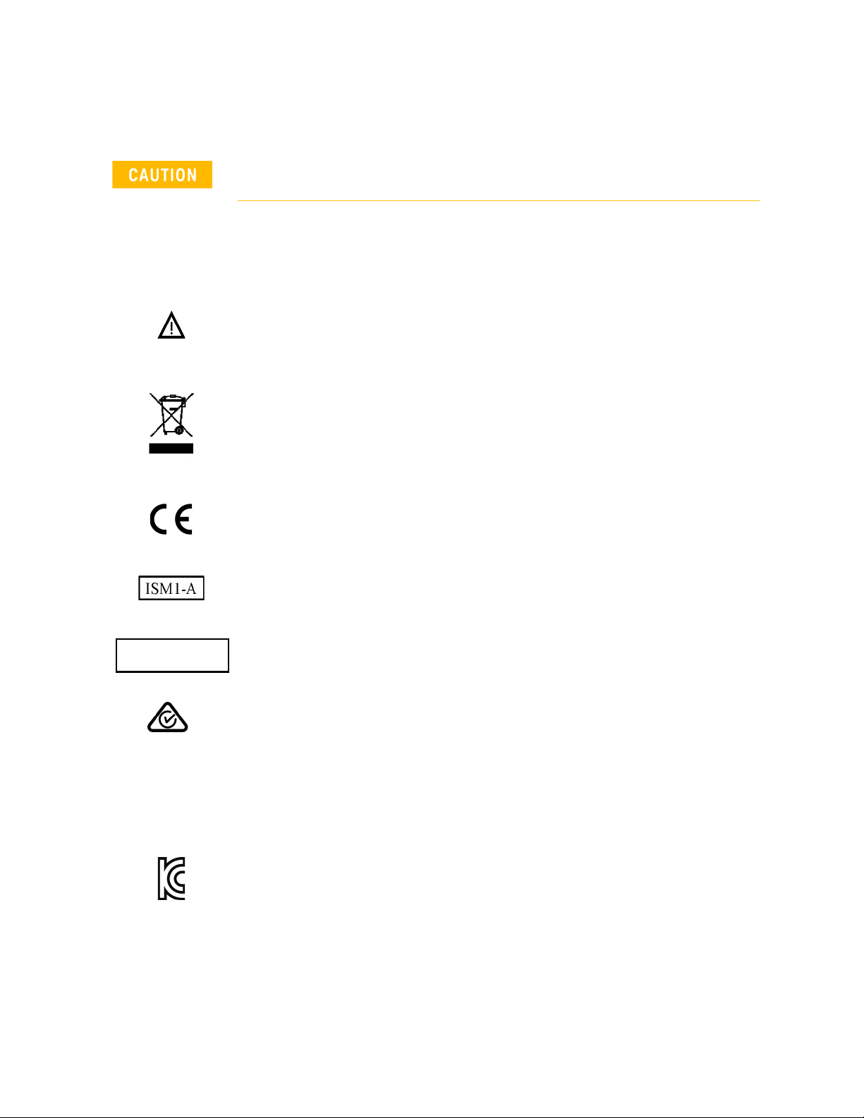
Table 1-13
ICES/NMB-001
General Information
Safety and Regulatory Information
Safety Notices
Use a dry cloth or one slightly dampened with water to clean the external
case parts. Do not attempt to clean internally.
Instrument Markings
The instruction documentation symbol. The product is marked with this symbol when it is
necessary for the user to refer to the instructions in the documentation.
This symbol indicates separate collection for electrical and electronic equipment, mandated
under EU law as of August 13, 2005. All electrical and electronic equipment are required to be
separated from normal waste for disposal (Reference WEEE Directive, 2002/96/EC.
The CE marking is a legal compliance marking of the European Community. This CE marking
shows that the product complies with all the relevant European Legal Directives.
This mark designates the product is an Industrial Scientific and Medical Group 1 Class A
product (reference CISPR 11, Clause 5).
This ISM device complies with Canadian ICES -001.
Cet appareil ISM est conforme a la norme NMB du Canada.
The RCM mark is a registered trademark of the Australian Communications and Media
Authority.
China RoHS regulations include requirements related to packaging, and require compliance to
China standard GB18455-2001.
Korean Certification (KC) mark; includes the marking’s identifier code which follows the format:
KCC-REM-YYY-ZZZZZZZZZZZZZZ or MSIP-REM-YYY-ZZZZZZZZZZZZZZ or R-R-Kst-xxxxxxx.
Electronic Calibration Modules Reference Guide 1-33
Page 42
1-
General Information
Safety and Regulatory Information
Table 1-13
This symbol indicates compliance with China RoHS regulations for paper/fiberboard
packaging.
Compliance Notices
This product has been designated and tested in accordance with accepted
industry standards, and has been supplied in a safe condition. The
documentation contains information and warnings that must be followed by
the user to ensure safe operation and to maintain the product in a safe
condition.
EMC and Safety Information
EMC
Complies with the essential requirements of the European EMC Directive as
well as current editions of the following standards (dates and editions are cited
in the Declaration of Conformity):
— IEC/EN 61326-1
— CISPR Pub 11 Group 1, class A
— AS/NZS CISPR 11
— ICES/NMB-001
This ISM device complies with Canadian ICES-001.
Cet appareil ISM est conforme a la norme NMB-001 du Canada.000
South Korean Class A EMC declaration
This equipment has been conformity assessed for use in business
environments. In a residential environment this equipment may cause radio
interference.
1-34 Electronic Calibration Modules Reference Guide
Page 43

General Information
Safety and Regulatory Information
Safety Information
European Low Voltage Directive is not applicable for these products.
Declaration of Conformity
A declaration of conformity for any of these ECal modules is available at
http://www.keysight.com/go/conformity or by contacting Keysight - see
“Contacting Keysight” on page 1-29.
Electronic Calibration Modules Reference Guide 1-35
Page 44

1-
General Information
Safety and Regulatory Information
1-36 Electronic Calibration Modules Reference Guide
Page 45

Keysight Electronic Calibration Modules
RF/Microwave Two Port
Reference Guide
2 Preparing ECal for Use
Inspecting the ECal Kit
Inspect the Kit Contents
Verify the case and its contents are not damaged and that all parts are
included (see items listed in Table 2-9). If the case or any device appears
damaged, or if the shipment is incomplete, contact Keysight. Keysight will
arrange for repair or replacement of incomplete or damaged shipments
without waiting for settlement from the transportation company. See
“Contacting Keysight” on page 1-29.
Locate the Serial Number
Your ECal kit has a unique serial number. The serial number is printed on a
label on the backside of the ECal module.
ECal Kit Serial Number
The serial number with the MY/US prefix on the backside of the ECal module is
assigned to the ECal kit. Refer to Figure 2-1. The ECal kit contains the ECal
module and, depending on the option configuration, accessories such as
wrenches and adapters.
2- 1
Page 46

2-
Preparing ECal for Use
Inspecting the ECal Kit
Figure 2-1 ECal Model and Serial Numbers on the Backside of the ECal Module
The ECal kit serial number is intended for identification purposes whenever an
ECal kit is returned to Keysight for repair or recertification.
ECal Module Serial Number
The serial number is located on the backside of the ECal module (refer to
Figure 2-1). Each ECal module is unique and is individually serialized. The
serial number is stored in the ECal module memory and may be accessed by a
network analyzer when the ECal is used to perform a calibration. Test reports
for an ECal module will refer to this serial number as the “ECal S/N.”
2-2 Electronic Calibration Modules Reference Guide
Page 47

Preparing ECal for Use
Inspecting the ECal Kit
Record the Serial Number
Record the serial number and the date of initial use as a reminder for annual
recertification. See “Recertification of ECal Modules” on page 1-30.
Table 2-1 Table for Tracking Serial Numbers
ECal Kit
Model Number
ECal Kit Serial Number
(contains MY/US prefix)
Verify Electrical Performance
To verify electrical performance of the module, see “Validating a Calibration”
on page 3-11.
Equipment Required but Not Supplied
Pin Depth Gages
Gages for measuring recession or protrusion are not provided in the kit. See
Chapter 6, “Replaceable Parts.” or contact Keysight to order gages and other
test accessories.
Date of Initial Use
Electronic Calibration Modules Reference Guide 2-3
Page 48

2-
Preparing ECal for Use
Kit Contents
Kit Contents
8509xD Series Kit Contents
The following table lists the items in each N8509xD kit.
Table 2-2 85091D Kit Contents
Qty Description Part No.
85091D
1 85091D, ECal Module --
1 South Korean Class A EMC Declaration 5061-7383
1 Calibration certificate 5962-0476
1 China RoHS Addendum for Test
Accessories-RF and Microwave
1 USB A-plug to micro-B plug Cable, 2 m 8121-2671
1 Critical Care Document 85051-90032
1 Transit case 1540-2367
1 Wrench – Torque 12 in-lb., 3/4 in. open end 8710-1766
1 QuickStart Guide 85092-90001
1 Unbox Guide 85092-90002
9320-6695
2-4 Electronic Calibration Modules Reference Guide
Page 49

Preparing ECal for Use
Kit Contents
Table 2-3 85092D Kit Contents
Qty Description Part No.
85092D
1 85092D, ECal Module --
1 South Korean Class A EMC Declaration 5061-7383
1 Calibration certificate 5962-0476
1 China RoHS Addendum for Test
Accessories-RF and Microwave
1 USB A-plug to micro-B plug Cable, 2 m 8121-2671
1 Critical Care Document 85051-90032
1 Transit case 1540-2367
1 Wrench – Torque 12 in-lb., 3/4 in. open end 8710-1766
1 QuickStart Guide 85092-90001
1 Unbox Guide 85092-90002
9320-6695
Electronic Calibration Modules Reference Guide 2-5
Page 50

2-
Preparing ECal for Use
Kit Contents
Table 2-4 85093D Kit Contents
Qty Description Part No.
85093D
1 85093D, ECal Module --
1 South Korean Class A EMC Declaration 5061-7383
1 Calibration certificate 5962-0476
1 China RoHS Addendum for Test
9320-6695
Accessories-RF and Microwave
1 USB A-plug to micro-B plug Cable, 2 m 8121-2671
1 Critical Care Document 85051-90032
1 Transit case 1540-2367
1 Wrench – Torque 8 in-lb., 20 mm open end 8710-1764
1 Wrench – Torque 8 in-lb., 20 mm open end 8710-1765
1 Wrench spanner 08513-20014
1 QuickStart Guide 85092-90001
1 Unbox Guide 85092-90002
2-6 Electronic Calibration Modules Reference Guide
Page 51

Preparing ECal for Use
Kit Contents
Table 2-5 85094D Kit Contents
Qty Description Part No.
85094D
1 85094D, ECal Module --
1 South Korean Class A EMC Declaration 5061-7383
1 Calibration certificate 5962-0476
1 China RoHS Addendum for Test
Accessories-RF and Microwave
1 USB A-plug to micro-B plug Cable, 2 m 8121-2671
1 Critical Care Document 85051-90032
1 Transit case 1540-2367
1 Wrench – Torque 22 mm 12 in-lb 8710-2811
1 QuickStart Guide 85092-90001
1 Unbox Guide 85092-90002
9320-6695
Electronic Calibration Modules Reference Guide 2-7
Page 52

2-
Preparing ECal for Use
Kit Contents
Table 2-6 85096D Kit Contents
Qty Description Part No.
85096D
1 85096D, ECal Module --
1 South Korean Class A EMC Declaration 5061-7383
1 Calibration certificate 5962-0476
1 China RoHS Addendum for Test
9320-6695
Accessories-RF and Microwave
1 USB A-plug to micro-B plug Cable, 2 m 8121-2671
1 Critical Care Document 85051-90032
1 Transit case 1540-2367
1 Wrench – 1/2 in. to 5/16 in. open end 8710-1770
1 Wrench – Torque 12 in-lb., 3/4 in. open end 8710-1766
1 QuickStart Guide 85092-90001
1 Unbox Guide 85092-90002
2-8 Electronic Calibration Modules Reference Guide
Page 53

Preparing ECal for Use
Kit Contents
Table 2-7 85098D Kit Contents
Qty Description Part No.
85098D
1 85098D, ECal Module --
1 South Korean Class A EMC Declaration 5061-7383
1 Calibration certificate 5962-0476
1 China RoHS Addendum for Test
Accessories-RF and Microwave
1 USB A-plug to micro-B plug Cable, 2 m 8121-2671
1 Critical Care Document 85051-90032
1 Transit case 1540-2367
1 Tool–hand and miscellaneous hard
chrome–finish
1 Torque–Wrench 2.26 N–m 1–1/16 in
hard-chrome finish
1 QuickStart Guide 85092-90001
1 Unbox Guide 85092-90002
9320-6695
8710-2174
8710-2175
Electronic Calibration Modules Reference Guide 2-9
Page 54

2-
Preparing ECal for Use
Kit Contents
Table 2-8 85099D Kit Contents
Qty Description Part No.
85099D
1 85099D, ECal Module --
1 South Korean Class A EMC Declaration 5061-7383
1 Calibration certificate 5962-0476
1 USB A-plug to micro-B plug Cable, 2 m 8121-2671
1 Critical Care Document 85051-90032
1 Transit case 1540-2367
1 Type F Wrench 8710-1841
1 QuickStart Guide 85092-90001
1 Unbox Guide 85092-90002
2-10 Electronic Calibration Modules Reference Guide
Page 55

Preparing ECal for Use
Kit Contents
N755xA Series Kit Contents
The following table lists the items in each N755xA kit.
Table 2-9 N755xA Kit Contents
Qty Description Part No.
N755xA
1 N755xA, ECal Module --
1 South Korean Class A EMC Declaration 5061-7383
1 Calibration certificate 5962-0476
2 Foam cushion set 30.5x23.5x14-cm
0.9-lbs-Density Polyethylene
1 Lanyard 9223-1111
1 China RoHS Addendum for Test
Accessories-RF and Microwave
1 Finding Product Manual Sheet 9320-6794
1 Assy, lanyard N7550-60008
1 USB A-plug to micro-B plug Cable, 2 m 8121-2671
1 QuickStart Guide N7550-90001
9220-8151
9320-6695
Electronic Calibration Modules Reference Guide 2-11
Page 56
2-
Preparing ECal for Use
Kit Contents
N4431D Series Kit Contents
The following tables list the items in each N4431D kit. For the N4431D kit,
Option 010 is configured with 3.5 mm -f- connectors on all ports and Option
020 is configured with type-N 50 ohm -f- connectors on all ports. See
Table 1-4 on page 1-13 for other configurations available.
Table 2-10 N4431D Kit Contents
Qty Description Part No.
N4431D Option 010
1 N4431D, ECal Module --
1 Calibration certificate 5962-0476
1 Wrench spanner 08513–20014
1 Wrench–Torque 8 in-lb, 20 mm open end 8710-1764
1 Wrench–Torque 8 in-lb, 5/16 in open end 8710-1765
1 USB A-plug to micro-B plug Cable, 2 m 8121-2671
1 3.5 mm Inner contact tool
4 3.5 mm Inner contact
5022-9143
5021-6558
1 QuickStart Guide N4431-90004
a. Only available for Option 010 and mixed options with 3.5 mm
-f- connectors. See also, https://literature.cdn.key-
sight.com/litweb/pdf/N4431-90013.pdf.
Table 2-11 N4431D Kit Contents
Qty Description Part No.
N4431D Option 020
1 N4431D, ECal Module --
1 Calibration certificate 5962-0476
1 Wrench–Torque 8 in-lb, 3/4 in open end 8710-1766
a
a
1 USB A-plug to micro-B plug Cable, 2 m 8121-2671
1 QuickStart Guide N4431-90004
2-12 Electronic Calibration Modules Reference Guide
Page 57

Preparing ECal for Use
Kit Contents
Table 2-12 N4431D Kit Contents
Qty Description Part No.
N4431D Mixed Connector Options
a
1 N4431D, ECal Module --
1 Calibration certificate 5962-0476
1 USB A-plug to micro-B plug Cable, 2 m 8121-2671
1 3.5 mm Inner contact tool
4 3.5 mm Inner contact
5022-9143
5021-6558
b
b
1 QuickStart Guide N4431-90004
a. Torque wrench varies with options.
b. Only available for Option 010 and mixed options with 3.5 mm
-f- connectors. See also, https://literature.cdn.key-
sight.com/litweb/pdf/N4431-90013.pdf.
Electronic Calibration Modules Reference Guide 2-13
Page 58

2-
Preparing ECal for Use
Kit Contents
N469xD Seres Kit Contents
Table 2-13 N469xD Kit Contents
Qty Description Part No.
N469xD
1 N469xD, ECal Module --
1 South Korean Class A EMC Declaration 5061-7383
1 Calibration certificate 5962-0476
2 Foam cushion set 46.0x33.0x16.7-cm Density
9220-8171
Polyethylene
1 China RoHS Addendum for Test
9320-6695
Accessories-RF and Microwave
1 Finding Product Manual Sheet 9320-6794
1 USB A-plug to micro-B plug Cable, 2 m 8121-2671
1 Critical Care Document 85051-90032
1 Transit case 1540-2345
1 Wrench – 1/2 in. to 5/16 in. open end 8710-1770
1 Wrench – Torque 8 in-lb., 20 mm open end
1 Wrench – Torque 8 in-lb., 20 mm open end
1 Wrench – Torque 12 in-lb., 3/4 in. open end
8710-1764
8710-1765
8710-1766
a
a
b
1 QuickStart Guide N4690-90002
a. 8710-1764 and 8170-1765 are only available for the N4691/2/3/4D models.
b. 8710-1766 wrench is only available for the N460/6D models.
2-14 Electronic Calibration Modules Reference Guide
Page 59
Preparing ECal for Use
Kit Contents
N4432D and N4433D Series Kit Contents
The following tables list the items in each N4432D and N4433D kit. For the
N4432D kit, Option 020 is configured with type-N 50 ohm -f- connectors on all
ports. For the N4433D kit, Option 010 is configured with 3.5 mm -f- connectors
on all ports. See Table 1-7 on page 1-20 and Table 1-8 on page 1-20 for other
configurations available.
Table 2-14 N4432D Kit Contents
Qty Description Part No.
N4432D Option 020
1 N4432D, ECal Module --
1 Calibration certificate 5962-0476
1 Torque Wrench 3/4 in, 1.3 N–m 8710-1766
1 USB A-plug to micro-B plug Cable, 2 m 8121-2671
1 QuickStart Guide N4431-90004
Table 2-15 N4432D Kit Contents
Qty Description Part No.
N4432D Mixed Connector Options
1 N4432D, ECal Module --
1 Calibration certificate 5962-0476
1 USB A-plug to micro-B plug Cable, 2 m 8121-2671
1 3.5 mm Inner contact tool
4 3.5 mm Inner contact
1 QuickStart Guide N4431-90004
a. Torque wrench varies with options.
b. Only available for Option 010 and mixed options with 3.5 mm
-f- connectors. See also, https://literature.cdn.key-
sight.com/litweb/pdf/N4431-90013.pdf.
a
5022-9143
5021-6558
b
b
Electronic Calibration Modules Reference Guide 2-15
Page 60

2-
Preparing ECal for Use
Kit Contents
Table 2-16 N4433D Kit Contents
Qty Description Part No.
N4433D Option 010
1 N4433D, ECal Module --
1 Calibration certificate 5962-0476
1 Torque Wrench 20 mm, 0.9 N-m 8710-1764
1 Torque Wrench 5/16”, 0.9 N-m 8710-1765
1 Wrench spanner N4431-20014
1 USB A-plug to micro-B plug Cable, 2 m 8121-2671
1 3.5 mm Inner contact tool
4 3.5 mm Inner contact
5022-9143
5021-6558
1 Quick Start Reference Guide N4431-90004
a. Only available for Option 010 and mixed options with 3.5 mm
-f- connectors. See also, https://literature.cdn.key-
sight.com/litweb/pdf/N4431-90013.pdf.
Table 2-17 N4433D Kit Contents
Qty Description Part No.
N4433D Mixed Connector Options
1 N4433D, ECal Module --
1 Calibration certificate 5962-0476
1 Torque Wrench 20 mm, 0.9 N-m 8710-1764
1 Torque Wrench 5/16”, 0.9 N-m 8710-1765
1 Wrench spanner N4431-20014
1 USB A-plug to micro-B plug Cable, 2 m 8121-2671
a
a
1 3.5 mm Inner contact tool
4 3.5 mm Inner contact
5022-9143
5021-6558
a
a
1 Quick Start Reference Guide N4431-90004
a. Only available for Option 010 and mixed options with 3.5 mm
-f- connectors. See also, https://literature.cdn.key-
sight.com/litweb/pdf/N4431-90013.pdf.
2-16 Electronic Calibration Modules Reference Guide
Page 61

Options
Preparing ECal for Use
Options
8509xD Options
Where:
— Option 00F, configures the module with female-to-female connectors.
— Option 00M, configures the module with male-to-male connectors.
— Option M0F, configures the module with male-to-female connectors.
N755xA Options
Where “x” represents the connector type (i.e., “N” for 50Ω Type-N and “3” for
3.5 mm:
— Option xFF, configures the module with female-to-female connectors.
— Option xMM, configures the module with male-to-male connectors.
— Option xMF, configures the module with male-to-female connectors.
N4431D Options
— Option 010 configures the model with 3.5 mm –f– and 020 configures the
module with Type-N 50 ohm -f- connectors on all ports.
— Option UK6 adds a commercial calibration certificate with measured data.
— For more, refer to “N4431D Modules (RF Four-Port)” on page 1-11
N469xD Options
Where:
— Option F0F, configures the module with female-to-female connectors.
— Option M0M, configures the module with male-to-male connectors.
— Option M0F, configures the module with male-to-female connectors.
N4432D Options
— Option 020 configures the module with Type-N 50 ohm -f- connectors on
all ports.
— Option UK6 adds a commercial calibration certificate with measured data.
— For more, refer to “N4432D and N4433D Modules (Microwave Four-Port)”
on page 1-18
Electronic Calibration Modules Reference Guide 2-17
Page 62

2-
Preparing ECal for Use
Operating and Safety Precautions
N4433D Options
— Option 010 configures the module with 3.5 mm -f- connectors on all ports.
— Option UK6 adds a commercial calibration certificate with measured data.
— For more, refer to “N4432D and N4433D Modules (Microwave Four-Port)”
on page 1-18
Operating and Safety Precautions
Observe the following guidelines before connecting or operating your ECal
module.
ESD Damage
Protection against electrostatic discharge (ESD) is important while handling
and operating your ECal module. Static electricity can build up on your body
and can easily damage sensitive components when discharged. Static
discharges too small to be felt can cause permanent damage to the unit. To
prevent damage from ESD:
— Use a grounded anti static mat in front of your test equipment and wear a
grounded wrist strap attached to it when handling or operating the ECal
module.
— Wear a heel strap when working in an area with a conductive floor.
— Ground yourself before you clean, inspect, or make a connection to an ECal
module. You can, for example, grasp the grounded outer shell of the
analyzer test port or cable connector briefly.
— Avoid touching the center conductor of the test ports.
For more information about preventing ESD, see “Electrostatic Discharge” on
page 4-1.
Connector Care
Because connectors can become defective due to wear during normal use, all
connectors should be inspected and maintained to maximize their service life.
For more detailed information, see “Visual Inspection” on page 4-3.
— Inspect the mating surface each time a connection is made. Metal particles
from connector threads often find their way onto the mating surface when a
connection is made or disconnected.
— Clean dirt and contamination from the connector mating surface and
threads. This simple step can extend the service life of the connector and
improve the quality of your calibration and measurements.
2-18 Electronic Calibration Modules Reference Guide
Page 63

Preparing ECal for Use
Operating and Safety Precautions
— Gage connectors periodically. This not only provides assurance of proper
mechanical tolerances, and thus connector performance, but can also
indicate situations where the potential for damage to another connector
may exist.
ECal modules can be damaged if you apply excessive torque to the
connectors. See Table 4-1 on page 4-21 for required torque settings.
Electronic Calibration Modules Reference Guide 2-19
Page 64
2-
Preparing ECal for Use
Operating and Safety Precautions
Input Power Level
Before performing a calibration, make sure the input power and DC levels
do not exceed the values indicated in Table 2-18.
Table 2-18 Input Power Limits <<DELETE THIS TEXT & Duplicate table Below for 8509xD
<SHP>>>
Parameter
Typical Maximum Input Power (linearity)
Typical Maximum DC Level Applied to Test Port
Typical Damage Level
a. If the maximum input power is exceeded when calibrating, compression may occur.
b. When using the PNA-X, the power level can be increased after calibration with minimal impact on
measurement accuracy.
c. Maximum DC level applied to test port, where Option 0DC for N469xD and N443xD is set to 0 volts.
Table 2-19 Input Power Limits
Parameter ECal Module Series
Typical Maximum Input Power (linearity)
Typical Maximum DC Level Applied to Test Port
ECal Module Series
8509xD
a, b
–5.0 dBm –15.0 dBm –5.0 dBm -7.0 dBm
c
±10 Volts
+10.0 dBm +10.0 dBm +10.0 dBm +20.0 dBm
N755xA N469xD N4431/2/3D
0 Volts
±10 Volts
± 3 Volts
N755xA N469xD N4431/2/3D
a, b
–15.0 dBm –5.0 dBm -7.0 dBm
c
0 Volts
±10 Volts
± 3 Volts
Typical Damage Level
a. If the maximum input power is exceeded when calibrating, compression may occur.
b. When using the PNA-X, the power level can be increased after calibration with minimal
impact on measurement accuracy.
c. Maximum DC level applied to test port, where Option 0DC for N469xD and N443xD is set to 0
volts.
+10.0 dBm +10.0 dBm +20.0 dBm
Operating Temperature
The temperature of the ECal module must be within the following temperature
range to meet the operating specifications.
— 8509xD Series: +20 °C to +26 °C and up to 95% relative humidity (RH) at
40 °C, non-condensing.
— N755xA Series: +15 °C to +35 °C and up to 75% relative humidity (RH).
— N469xD Series: +20 °C to +26 °C and up to 95% relative humidity (RH) at
40 °C, non-condensing.
2-20 Electronic Calibration Modules Reference Guide
Page 65

Preparing ECal for Use
Operating and Safety Precautions
— N443xD Series: +20 °C to +26 °C and up to 95% relative humidity (RH) at
40 °C, non-condensing.
For more details, see “Environmental Specifications” on page 5-2.
Electronic Calibration Modules Reference Guide 2-21
Page 66

2-
Preparing ECal for Use
Operating and Safety Precautions
2-22 Electronic Calibration Modules Reference Guide
Page 67
Keysight Electronic Calibration Modules
RF/Microwave Two Port
Reference Guide
3 Operating ECal Module
Setting Up a Calibration
Use the following procedure as a starting point for calibrating the network
analyzer with an ECal module. For more detailed information about adjusting
the settings of your analyzer, refer to the appropriate user guide or online Help.
Understanding the ECal LEDs
The ECal module has three different LEDs that may be displayed during
operation:
Table 3-1 N755xA Status LED Operation
Status LED Color Description
Off
Steady Green
Orange
a. Status LED briefly flashes orange when the ECal is first connected to an instrument while the
driver software loads.
— ECal is not connected to an
instrument or is malfunctioning.
— See also, Figure “ECal
Troubleshooting” on page 3-14.
— ECal is connected, functioning, and
communicating normally
— ECal connected and functioning, but
is not communicating with the driver
software.
— See also, Figure “ECal
Troubleshooting” on page 3-14.
a
3- 1
Page 68
3-
Operating ECal Module
Setting Up a Calibration
Table 3-2 8509xD, N443xD and N469xD Status LED Operation
Status LED Color Description
Off
Orange
Steady Green
Alternating Green/Orange Flashing
— ECal is not connected to an
instrument or is malfunctioning.
— See also, Figure “ECal
Troubleshooting” on page 3-14.
— ECal is warming up.
— ECal connected and functioning, but
is not communicating with the driver
software.
— See also, Figure “ECal
Troubleshooting” on page 3-14.
— ECal is connected, functioning,
warmed up, and communicating
normally.
a
— ECal is too cold and unable to
regulate internal temperature to
setpoint.
— Performance may be degraded
beyond specifications.
— See also, Figure “ECal
Troubleshooting” on page 3-14.
Alternating Green/Red Flashing
—ECal is too hot and unable to
regulate internal temperature to
setpoint.
— Performance may be degraded
beyond specifications.
— See also, Figure “ECal
Troubleshooting” on page 3-14.
a. Status LED briefly flashes orange when the ECal is first connected to an instrument while the
driver software loads.
3-2 Electronic Calibration Modules Reference Guide
Page 69
Operating ECal Module
Setting Up a Calibration
Required Procedure for All Calibrations (PNA and PXIe)
For all calibration types, complete the following steps:
1. Connect an ECal module to the analyzer having the appropriate frequency
range and connector type.
2. Wait until LED turns green.
3. Set up the analyzer in the measurement configuration. Select the
frequency, power, sweep and other stimulus settings.
4. View the response (uncorrected) and optimize the analyzer settings as
needed.
5. Connect the ECal module to the measurement ports.
6. Navigate to Response > Cal Wizard
7. In the Calibration Wizard: Begin Calibration window that opens, select Use
Electronic Calibration (ECal), click Next, and follow the prompts.
8. When the calibration is complete, remove the ECal module, and connect
the DUT.
Excessive torque can damage ECal module connectors. See Table 4-1 on
page 4-21 for the required torque setting for each connector type.
For optimal results, terminate any unused ECal ports with a 50 ohm load.
Required Procedure for All Calibrations (ENA E5061B, E5063A, E5071C, and
E5072A)
For all calibration types, complete the following steps:
1. Connect an ECal module to the analyzer having the appropriate frequency
range and connector type.
2. Wait until LED turns green.
3. Set up the analyzer in the measurement configuration. Select the
frequency, power, sweep and other stimulus settings.
4. View the response (uncorrected) and optimize the analyzer settings as
needed.
5. Connect the ECal module to the measurement ports.
6. Select the channel you want to calibrate: Press Channel Next/Channel
Prev keys
7. Press Cal
8. Click ECal > 1-Port Cal
Electronic Calibration Modules Reference Guide 3-3
Page 70
3-
Operating ECal Module
Setting Up a Calibration
9. Perform a 1-port calibration by clicking the softkey of the selected port.
10.Refer to the ENA User’s Guide or Online Help for more details on
performing various types of 1-port calibrations. Refer to your instrument’s
Online Help/User’s Guide on http://ww.keysight.com.
11.When the calibration is complete, remove the ECal module, and connect
the DUT.
Excessive torque can damage ECal module connectors. See Table 4-1 on
page 4-21 for the required torque setting for each connector type.
For optimal results, terminate any unused ECal ports with a 50 ohm load.
Required Procedure for All Calibrations (FieldFox)
For all calibration types, complete the following steps:
1. Connect an ECal module to the FieldFox having the appropriate frequency
range and connector type.
2. Wait until LED turns green.
3. Set up the analyzer in the measurement configuration. Select the
frequency, power, sweep and other stimulus settings.
Verify the FieldFox is set to a frequency range that is within the ECal
module’s range. If the frequency start and or stop frequency are outside
the range of the ECal module, the FieldFox does not recognize the ECal
module.
4. View the response (uncorrected) and optimize the analyzer settings as
needed.
5. Connect the ECal module to the measurement ports.
6. Set instrument to frequency range that is compatible with your ECal
module.
7. Navigate to Cal 5 > Mechanical Cal / ECal.
For each test port to be calibrated, press the Change DUT Connectors and
follow the prompts.
IMPORTANT: Until the correct connector-type is selected for your ECal
module, the ECal module choice(s) will not be visible in the Select
CalKit table.
3-4 Electronic Calibration Modules Reference Guide
Page 71
Operating ECal Module
Setting Up a Calibration
8. Press Change Cal Type. The connected ECal module and relevant User
Characterizations will appear, with the ECal factory default as the default
Cal Kit. In the Select Calkit table that opens, verify the correct ECal model
is selected. If not, use the arrow keys to select the correct ECal model.
9. Press Finish
10. Press Start Calibration.
11. In the Calibration Wizard window that opens, press Measure.
12. Continue to follow the prompts for the other port and when the
calibration is complete, remove the ECal module, and connect the DUT.
For more information on using an ECal module with the FieldFox, refer to
the User’s Guide for your model on www.keysight.com.
Excessive torque can damage ECal module connectors. See Table 4-1 on
page 4-21 for the required torque setting for each connector type.
For optimal results, terminate any unused ECal ports with a 50 ohm load.
Electronic Calibration Modules Reference Guide 3-5
Page 72

3-
Operating ECal Module
Setting Up a Calibration
Calibration Types Available
The following table contains the calibration types and advanced settings
available for all compatible network analyzers:
Table 3-3 Calibration Types and Advanced Settings Available
Calibration Types Model
PNA PXIe Streamline
ENA
FieldFox
a
VNA
1-Port Reflection Yes Yes Yes Yes Yes
Full 2-Port Yes Yes Yes Yes Yes
Full N-Port where N>2 Yes Yes Yes Yes No
Enhanced Response Yes Yes Yes Yes Yes
QSOLT Yes Yes Yes No Yes
Advanced Settings
Adapter Removal Yes Yes Yes No No
Flush (zero length) THRU Yes Yes Yes No Yes
Unknown THRU Yes Yes Yes Yes Yes
User-Characterization Yes Yes Yes Yes
a. ECal calibrations are not supported on the N9912A.
b. FieldFox user-characterizations must be performed on a PNA or ENA. Learn more about User
Characterization at the PNA Help website: http://na.support.keysight.com/pna/help/latest/S3_-
Cals/ECal_User_Characterization.htm
Yes
b
3-6 Electronic Calibration Modules Reference Guide
Page 73

Operating ECal Module
Setting Up a Calibration
When to Correct for Isolation
Correction for isolation is a consideration when measuring high-loss devices
such as saw filters or diplexers. When maximum dynamic range is required,
correction for isolation can remove the errors due to crosstalk (between test
ports) for transmission measurements.
When you include isolation with a two, three, or four-port calibration, the
analyzer automatically applies averaging to reduce noise in the measurement.
Without averaging, you will have noise in the measurement of the crosstalk,
and could raise the noise floor when the analyzer uses this in its error
correction.
The analyzer system isolation is normally sufficient for most measurements,
and correction for it is usually unnecessary. As long as crosstalk is below the
noise floor, it is best NOT to correct for isolation using ECal. As of PNA firmware
release 4.26, measuring isolation as part of the ECal process is no longer
supported.
Electronic Calibration Modules Reference Guide 3-7
Page 74

3-
Operating ECal Module
Setting Up a Calibration
Calibration Methods for Non-Insertable Devices
A “non-insertable” device means that the measurement ports cannot be
connected together to establish a THRU connection during calibration for
transmission. Because the module typically forms the THRU path, you can use
one of the following methods to perform a calibration for non-insertable
devices:
Configure ECal Module the Same as Device
The simplest way to calibrate for non-insertable devices is to configure an ECal
module with the same connector types as the DUT. RF ECal modules can be
configured with mixed connectors to match the connector types on the DUT.
Refer to “Models and Options” on page 1-4. You can also configure the
module with different connector types by performing a User-Characterization
(see below).
Use Adapter Removal Calibration
Adapter removal provides an accurate way to calibrate for non-insertable
devices, but requires extra calibration steps to characterize the adapter. The
adapter type used for this calibration must be a -m- to -m- or -f- to -f- and
have the same connector type as the module. In addition, the module must
have a male connector on one test port and a female connector on the other
test port (of the same connector type).
Use Unknown Thru Calibration
Unknown Thru calibration is currently available with all PNA network analyzers
except the E8801/2/3A. It is easy to perform and can be used on any two ports
when using a multiport PNA. It causes minimal cable movement if the Thru
standard has the same footprint as the DUT. In fact, the DUT can often be the
Thru standard. A 1-port calibration is performed on both ports. The unknown
Thru is connected between the two ports and measured. Next, the user must
confirm the Estimated Delay. This requires knowing the phase response to
within 1/4 wavelength. If the phase response is unknown, the Delay value can
be measured independently and entered in the dialog box.
Perform a User-Characterization
Normally, when you perform a calibration with an ECal module, the error terms
for a calibration are computed using the factory characterization (data) stored
in the module. User-Characterization allows you change the characterization
of the module in two ways:
— Change the connector configuration: allows you to add an adapter or fixture
to the test port of the module and embed the effects into the
characterization of the module. The result of the new characterization
extends the reference plane from one or more of the module’s test ports to
those on the adapter (or fixture).
3-8 Electronic Calibration Modules Reference Guide
Page 75

Operating ECal Module
Setting Up a Calibration
— Modify the state settings: allows you to specify the number of data points
(1601 max.) or other stimulus settings the module uses to perform a
calibration.
When you perform a User-Characterization, the factory characterization data
remains stored in the module’s memory. At calibration, you can select the
factory characterization or any of the user-defined characterizations stored in
the module. The module can store up to five user-defined characterizations (in
addition to the factory characterization data).
User-Characterization is currently available with PNA and PXIe. FieldFox
user-characterizations must be performed on a PNA or ENA.
To perform a User-Characterization, a calibration kit (having the same
connector type as the new reference plane) is required.
For detailed information on calibration methods using an PNA or PXIe series
network analyzer or FieldFox, refer to the appropriate user guide or online
Help. To use the Internet to view the PNA or PXIe online Help, use the steps
listed in “Finding More Information on Performing a Calibration” on
page 3-10.
Electronic Calibration Modules Reference Guide 3-9
Page 76

3-
Operating ECal Module
Finding More Information on Performing a Calibration
Finding More Information on Performing a Calibration
For detailed information on performing a calibration using an PNA or PXIe
series or the FieldFox, refer to the appropriate user guide or online Help.
— To view the PNA or PXIe Help file that is embedded in the analyzer, press
the Help key on the front panel of the network analyzer.
— To view a user guide or Help file on the Internet, use the following steps:
1. Go to www.keysight.com.
2. Enter your analyzer model number (Ex: N5242A) in the search function and
click Search.
3. Click on the Manuals hyperlink.
4. Open the PDF of the User Guide or Help.
Do not perform a calibration procedure unless you have cleaned and
visually inspected all connectors and have taken the necessary ESD
precautions.
3-10 Electronic Calibration Modules Reference Guide
Page 77
Operating ECal Module
Validating a Calibration
Validating a Calibration
It is recommended that the Confidence Check be performed after every
calibration, to verify the device is still functioning as expected.
ECal Confidence Check and System Verification do not apply to the
FieldFox.
The accuracy of a completed calibration should be validated after each
calibration, because the following sources of error that can invalidate it:
— damaged semiconductor devices caused by static discharge or excess high
input power
—bad cables
— dirty or worn connectors
— operator error
— measurement uncertainties from interpolation
The following paragraphs discuss two methods of validating the accuracy of a
calibration:
1. Performing the ECal module’s ECal Confidence Check.
2. Performing the analyzer’s System Verification Procedure using standards
in a Keysight verification kit.
Which method you choose depends largely on the level of accuracy required
and the availability of a Keysight verification kit.
ECal Confidence Check – Basic Validation of the Calibration
It is recommended that the Confidence Check be performed after every
calibration, to verify the device is still functioning as expected.
The ECal Confidence Check allows you to measure an impedance state in the
ECal module – called the confidence state – and compare your measurement
data with factory measurement data stored in ECal memory (of the same
confidence state). The ECal Confidence Check overlays the two measurement
traces so that the differences between your data and the factory data can be
easily viewed.
— The ECal Confidence Check provides a basic validation that you have
completed the ECal calibration correctly and that the calibration is
activated.
Electronic Calibration Modules Reference Guide 3-11
Page 78
3-
Operating ECal Module
Validating a Calibration
— The ECal Confidence Check is not a method for system verification. The
ECal Confidence Check’s impedance state physically shares some of the
same hardware as the ECal calibration impedance states. System
verification requires a verification kit because it has devices that are
physically different from those in a calibration kit.
— Keysight recommends that upon receipt of a new ECal module, you perform
the ECal Confidence Check and save the measurement results as a baseline
for future reference.
— Periodically, it is recommended that additional ECal confidence checks be
performed and the test results compared to the baseline data.
— The interpretation of how much variation is acceptable between your data
and the factory data is determined by your level of confidence in the
calibration, based on your historical records of baseline data.
Before performing the ECal Confidence Check, the analyzer must be calibrated
and the calibration type should be appropriate for the measurement being
made. For example, you cannot measure the confidence state with an S22
measurement if an S11 1-port calibration is active.
For optimal results, terminate any unused ECal ports with a 50 ohm load.
For detailed information on performing an ECal Confidence Check using a
ENA, PNA, or PXIe series instruments, refer to the appropriate online Help. To
use the Internet to view the ENA, PNA, or PXIe online Help, use the steps listed
in “Finding More Information on Performing a Calibration” on page 3-10.
System Verification Procedure – Traceable Accuracy Validation of the Calibrated Measurement System
ECal Confidence Check and System Verification do not apply to the
FieldFox.
This method of validating the calibration requires a Keysight verification
kit.
Using your analyzer’s built-in System Verification Procedure to measure the
standards in a Keysight verification kit provides a traceable accuracy validation
of your calibrated measurement system. Following the measurement of each
standard, the System Verification Procedure provides a pass/fail result,
determining if your calibration provides measurements that meet the limits of
uncertainty.
— The analyzer’s built-in System Verification Procedure provides a traceable
accuracy validation that you have completed the ECal calibration correctly
and that the limits of uncertainty are met.
3-12 Electronic Calibration Modules Reference Guide
Page 79

Operating ECal Module
Validating a Calibration
— The System Verification Procedure is also a method for verifying the
performance of your analyzer.
— Verification kits use accurately known standards with well defined
magnitude and phase response. These kits include precision airlines,
mismatch airlines, and precision fixed attenuators.
— Each verification kit standard is measured precisely by Keysight’s accredited
test laboratory. The measurement data and uncertainty of each standard
are provided in each kit on a disk or USB storage drive.
— Verification kits may be re-certified by Keysight. Contact Keysight for
information about ordering verification kits - see “Contacting Keysight” on
page 1-29.
For detailed information on using your analyzer’s built-in System Verification
Procedure, refer to the appropriate service guide or online Help. To use the
internet to view the ENA, PNA, or PXIe online Help, use the steps listed in
“Finding More Information on Performing a Calibration” on page 3-10.
Electronic Calibration Modules Reference Guide 3-13
Page 80
3-
Operating ECal Module
ECal Troubleshooting
ECal Troubleshooting
Table 3-4 8509xD, N469xD/N443xD Troubleshooting
LED Color Description Possible Causes Solutions
Orange
Alternating
Green/Orange
Flashing
Alternating
Green/Red
Flashing
Off
ECal is connected
and functioning, but
is not
communicating with
driver software.
ECal is too cold and
unable to regulate
internal temperature
to setpoint.
ECal is too hot and
unable to regulate
internal temperature
to setpoint.
The ECal is not
functioning.
ECal module is connected to an
instrument (or PC) without the
appropriate driver software installed.
Faulty instrument USB port Connect to a different USB port on the
Faulty USB cable Connect via a different USB cable.
Faulty USB hub Connect ECal directly to a USB port on
ECal is too cold and unable to
regulate internal temperature to
setpoint.
ECal is too hot and unable to regulate
internal temperature to setpoint.
ECal is not connected to instrument. Double check the USB connectors are
Faulty instrument USB port Connect to a different USB port on the
Connect the ECal module to a
compatible instrument.
Ensure that the instrument software is
up to date.
instrument.
the instrument.
Move ECal to a warmer location. Refer
to “Environmental Specifications”
on page 5-2.
Move ECal to a cooler location. Refer to
“Environmental Specifications” on
page 5-2.
firmly inserted.
instrument.
Faulty USB cable Connect via a different USB cable.
Faulty USB hub Connect ECal directly to a USB port on
the instrument.
Faulty ECal module Return to Keysight for service. Refer to
Chapter 1, “Service and
Recertification” on page 1-29.
3-14 Electronic Calibration Modules Reference Guide
Page 81

Operating ECal Module
ECal Troubleshooting
Table 3-5 N755xA Troubleshooting
LED Color Description Possible Causes Solutions
Orange
Off
ECal is connected
and functioning, but
is not
communicating with
driver software.
The ECal is not
functioning.
ECal module is connected to an
instrument (or PC) without the
appropriate driver software installed.
Faulty instrument USB port Connect to a different USB port on the
Faulty USB cable Connect via a different USB cable.
Faulty USB hub Connect ECal directly to a USB port on
ECal is not connected to instrument. Double check the USB connectors are
Faulty instrument USB port Connect to a different USB port on the
Faulty USB cable Connect via a different USB cable.
Faulty USB hub Connect ECal directly to a USB port on
Faulty ECal module Return to Keysight for service. Refer to
Connect the ECal module to a
compatible instrument.
Ensure that the instrument software is
up to date.
instrument.
the instrument.
firmly inserted.
instrument.
the instrument.
Chapter 1, “Service and
Recertification” on page 1-29.
Electronic Calibration Modules Reference Guide 3-15
Page 82

3-
Operating ECal Module
ECal Troubleshooting
3-16 Electronic Calibration Modules Reference Guide
Page 83

Keysight Electronic Calibration Modules
RF/Microwave Two Port
Reference Guide
4 Use, Maintenance, and Care of the Devices
Electrostatic Discharge
Protection against electrostatic discharge (ESD) is essential while connecting,
inspecting, or cleaning devices attached to static-sensitive circuits (such as
those found in network analyzers and ECal modules).
Static electricity can build up on your body and can easily damage sensitive
internal circuit elements when discharged. Static discharges too small to be
felt can cause permanent damage. Devices such as calibration components
and devices under test (DUTs), can also carry an electrostatic charge. To
prevent damage to network analyzer components and devices:
— always wear a grounded wrist strap having a 1 MΩ resistor in series with it
when handling components and devices or when making connections to
the test set.
— always use a grounded, conductive table mat while making connections.
— always wear a heel strap when working in an area with a conductive floor. If
you are uncertain about the conductivity of your floor, wear a heel strap.
— always ground yourself before you clean, inspect, or make a connection to
a static-sensitive device or test port. You can, for example, grasp the
grounded outer shell of the test port or cable connector briefly.
— always ground the center conductor of a test cable before making a
connection to the analyzer test port or other static-sensitive device. This
can be done as follows:
1. Connect a short (from your calibration kit) to one end of the cable to
short the center conductor to the outer conductor.
2. While wearing a grounded wrist strap, grasp the outer shell of the
cable connector.
3. Connect the other end of the cable to the test port.
4. Remove the short from the cable.
For parts numbers for ESD protection supplies, refer to “Other ECal
Accessories” on page 6-12.
4- 1
Page 84
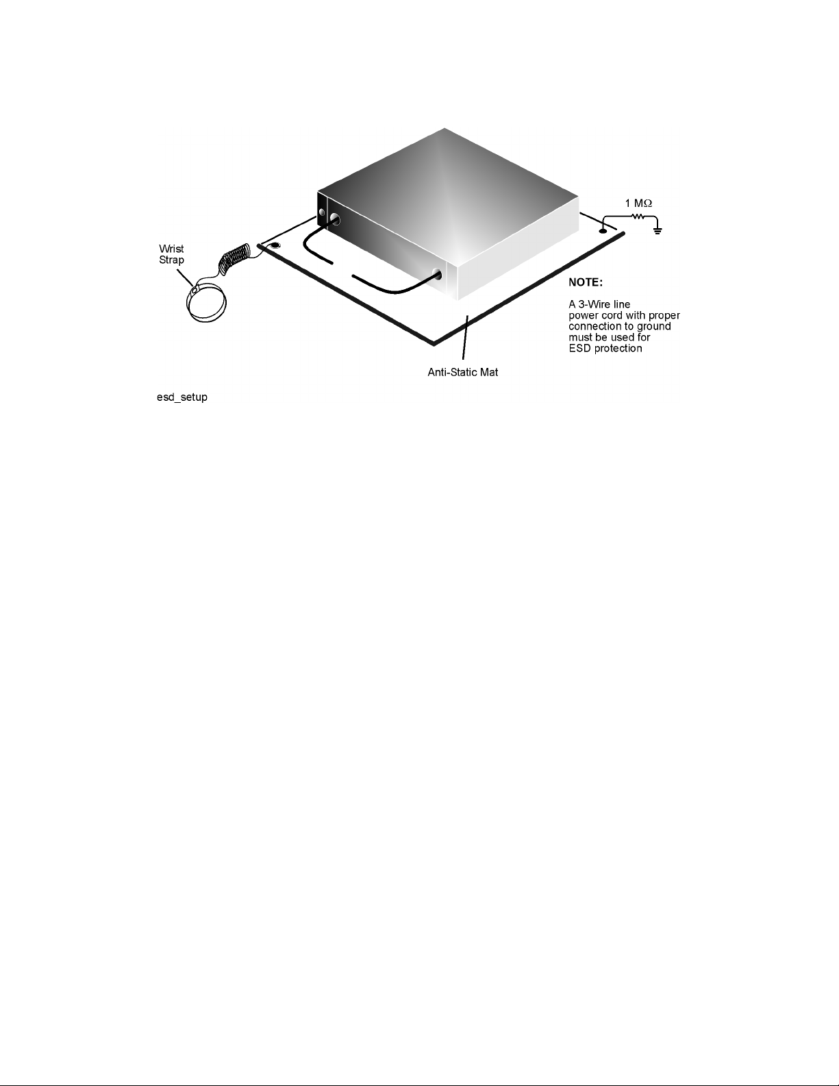
4-
Use, Maintenance, and Care of the Devices
Electrostatic Discharge
Figure 4-1 ESD Protection Using Mat, Wrist Strap, and Grounded Power Cord
4-2 Electronic Calibration Modules Reference Guide
Page 85

Visual Inspection
Use, Maintenance, and Care of the Devices
Visual Inspection
Visual inspection and, if necessary, cleaning should be done every time a
connection is made. Metal particles from the connector threads may fall into
the connector when it is disconnected.
Devices with damaged connectors should immediately be discarded or
clearly marked and set aside for repair. A damaged device will in turn
damage any good connector to which it is attached. Try to determine the
cause of the damage before connecting a new, undamaged connector in
the same configuration.
Magnification is helpful when inspecting connectors, but it is not required
and may actually be misleading. Defects and damage that cannot be seen
without magnification generally have no effect on electrical or mechanical
performance. Magnification is of great use in analyzing the nature and
cause of damage and in cleaning connectors, but it is not required for
inspection.
Look for Obvious Defects and Damage First
Examine the connectors first for obvious defects and damage: badly worn
plating on the connector interface, deformed threads, or bent, broken, or
misaligned center conductors.
What Causes Connector Wear?
Connector wear is caused by connecting and disconnecting the devices. The
more use the device gets, the faster it wears and degrades. The wear is greatly
accelerated when connectors are not kept clean, or are not properly
connected. This is especially true with electrically characterized devices such
as ECal modules. ECal modules should have a long life if their use is on the
order of a few times per week.
The test port connectors on the network analyzer may have many connections
each day, and are therefore more subject to wear. It is recommended that an
adapter be used as a test port saver to minimize the wear on the connectors.
Replace devices with worn connectors.
Inspect the Mating Plane Surfaces
Uniform contact between the connectors at all points on their mating plane
surfaces is required for a good connection. See Figure 4-2 for an example of
locations of mating plane surfaces. Look especially for deep scratches or
dents, and for dirt and metal particles on the connector mating plane surfaces.
Also look for signs of damage due to excessive or uneven wear or
misalignment.
Electronic Calibration Modules Reference Guide 4-3
Page 86
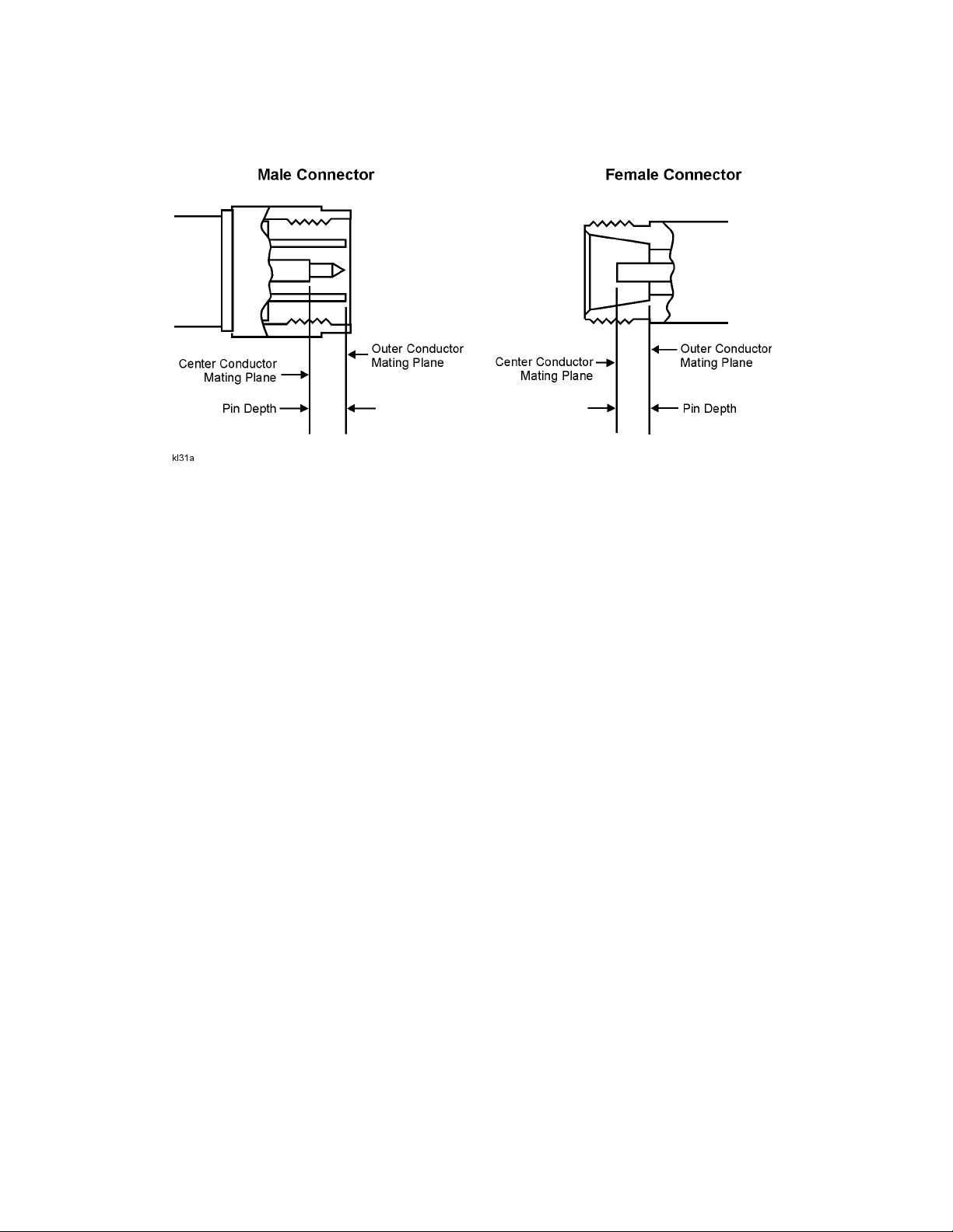
4-
Use, Maintenance, and Care of the Devices
Visual Inspection
Figure 4-2 Type-N Connector Pin Depth and Mating Surfaces
Light burnishing of the mating plane surfaces is normal, and is evident as light
scratches or shallow circular marks distributed more or less uniformly over the
mating plane surface. Other small defects and cosmetic imperfections are also
normal. None of these affect electrical or mechanical performance. If a
connector shows deep scratches or dents, particles clinging to the mating
plane surfaces, or uneven wear, clean and inspect it again.
4-4 Electronic Calibration Modules Reference Guide
Page 87
Use, Maintenance, and Care of the Devices
Inspect Female Connectors
Inspect Female Connectors
When using slotless connectors like the 3.5 mm or some Type-N 50 Ω female
connectors, pay special attention to the contact fingers on the female center
conductor. These can be bent or broken, and damage to them is not always
easy to see. A connector with damaged contact fingers will not make good
electrical contact and must be repaired or replaced.
Due to the tighter mechanical specifications of precision devices,
inspection is particularly important when you are mating nonprecision to
precision devices.
When a 3.5 mm female connector’s contact fingers are bent or broken, you
can perform a self-repair on the inner contacts by using a connector repair
kit.
The 3.5 mm Connector Repair Kit (for ordering information, refer to “Contacting Keysight”
on page 1-29
https://literature.cdn.keysight.com/litweb/pdf/N4431-90013.pdf).
), Installation Note (refer to
Electronic Calibration Modules Reference Guide 4-5
Page 88

4-
Use, Maintenance, and Care of the Devices
Cleaning Connectors
Cleaning Connectors
Clean connector interfaces prolong connector life and produce more accurate
and repeatable measurements.
Always use protective eyewear when using compressed air or
nitrogen.
The following cleaning procedure can be used for most coaxial connectors.
Cleaning Coax Connectors
1. Use compressed Air or Nitrogen
Use compressed air (or nitrogen) to loosen particles on the connector
mating plane surfaces.
You can use any source of clean, dry, low-pressure compressed air or
nitrogen that has an effective oil-vapor filter and liquid condensation trap
placed just before the outlet hose.
Ground the hose nozzle to prevent electrostatic discharge, and set the air
pressure to less than 414 kPa (60 psi) to control the velocity of the air
stream. High-velocity streams of compressed air can cause electrostatic
effects when directed into a connector. These electrostatic effects can
damage the device. For additional information refer to “Electrostatic
Discharge” on page 4-1 earlier in this chapter.
Keep isopropyl alcohol away from heat, sparks, and flame. Store in a
tightly closed container. Isopropyl alcohol is extremely flammable. In
case of fire, use alcohol foam, dry chemical, or carbon dioxide; water
may be ineffective.
Use isopropyl alcohol with adequate ventilation and avoid contact
with eyes, skin, and clothing. It causes skin irritation, may cause eye
damage, and is harmful if swallowed or inhaled. It may be harmful if
absorbed through the skin.
Wash thoroughly after handling. In case of spill, soak up with sand
or earth. Flush spill area with water.
Dispose of isopropyl alcohol in accordance with all applicable
federal, state, and local environmental regulation.
4-6 Electronic Calibration Modules Reference Guide
Page 89

Use, Maintenance, and Care of the Devices
Cleaning Connectors
2. Clean the Connector Threads
Use ONLY isopropyl alcohol to clean connector surfaces. Any other solvent
may damage the insulators, support beads, and seals in the connector.
Never immerse the connector in solvents of any kind. The solvent can
become trapped within the assembly and cause SWR, phase, and insertion
loss problems.
Moisten (don’t soak) a lint-free swab or cleaning cloth with isopropyl
alcohol to remove any dirt or stubborn contaminants that cannot be
removed with compressed air or nitrogen. Refer to “Other ECal
Accessories” on page 6-12 for cleaning swabs and other connector
cleaning supplies.
a. Apply a small amount of isopropyl alcohol to a lint-free swab.
b. Clean the connector threads.
c. Let the alcohol evaporate, then blow the threads dry with a gentle
stream of clean, low-pressure compressed air or nitrogen. Always
completely dry a connector before you reassemble or use it.
3. Clean the Mating Plane Surfaces
a. Apply a small amount of isopropyl alcohol to a new lint-free
cleaning cloth or swab.
b. Clean the center and outer conductor mating plane surfaces. Refer
to Figure 4-2 on page 4-4. When cleaning a female connector; use
short strokes to avoid snagging the swab on the center conductor
contact fingers.
c. Let the alcohol evaporate, then blow the mating plane surface dry
with a gentle stream of clean, low-pressure compressed air or
nitrogen. Always completely dry a connector before you reassemble
or use it.
4. Inspect Each Connector
Inspect the connector to make sure that no particles or residue are
present.
Cleaning 7 mm Connectors
Cleaning the Center Collet While It Is in Place
You do not have to remove the center conductor collet to clean a precision
7 mm connector.
With the center collet in place:
1. Place a lint-free cleaning cloth flat on a table.
Electronic Calibration Modules Reference Guide 4-7
Page 90

4-
Use, Maintenance, and Care of the Devices
Cleaning Connectors
2. Dispense a drop or two of isopropyl alcohol in the center of the cloth.
3. Retract the connector sleeve threads to expose the connector interface.
4. Gently press the contact end of the connector into the moistened cloth
and rotate the connector. The cloth scrubs away dirt on the connector
interface without damaging it.
5. Blow the connector dry with a gentle stream of compressed air or
nitrogen.
6. When not in use, keep the cloth in a plastic bag or box so that it does not
collect dust or dirt.
For fixed connectors (i.e., connectors attached to a device that cannot be freely
moved):
1. Fold a lint-free cleaning cloth several times.
2. Moisten the cloth with isopropyl alcohol.
3. Press the moistened cloth against the connector interface and rotate the
cloth to clean the connector.
4. Blow the connector dry with a gentle stream of compressed air or
nitrogen.
Cleaning a Removed Center Collet
Any time you remove the center conductor collet, clean and inspect the interior
surfaces as described in “Visual Inspection” on page 4-3.
4-8 Electronic Calibration Modules Reference Guide
Page 91

Use, Maintenance, and Care of the Devices
Gaging Connectors
Gaging Connectors
The gages available from Keysight Technologies are intended for preventive
maintenance and troubleshooting purposes only. They are effective in
detecting excessive center conductor protrusion or recession, and conductor
damage on DUTs, test accessories, and ECal module test ports. Do not use the
gages for precise pin depth measurements.
Connector Gage Accuracy
The connector gages are only capable of performing coarse measurements.
They do not provide the degree of accuracy necessary to precisely measure the
pin depth. This is partially due to the repeatability uncertainties that are
associated with pin-depth measurements.
With proper technique, the gages are useful in detecting gross pin depth errors
on device connectors. To achieve maximum accuracy, random errors must be
reduced by taking the average of at least three measurements having different
gage orientations on the connector. Even the resultant average can be in error
by as much as ±0.0001 inch (±0.0025 mm) due to systematic (biasing) errors
usually resulting from worn gages and gage masters. The information in
“Typical Pin Depth Values” on page 5-26 assumes new gages and gage
masters. Therefore, these systematic errors were not included in the
uncertainty analysis. As the gages endure more use, the systematic errors can
become more significant in the accuracy of the measurement.
The measurement uncertainties are primarily a function of the assembly
materials and design, and the unique interaction each device type has with the
gage. Therefore, these uncertainties can vary among the different devices.
The observed pin depth limits add in these uncertainties to the typical factory
pin depth values to provide practical limits that can be referenced when using
the gages.
When measuring pin depth, the measured value (resultant average of
three or more measurements) contains measurement uncertainty and is
not necessarily the true value. Always compare the measured value with
observed pin depth limits (which account for measurement
the
uncertainties) in “Typical Pin Depth Values” on page 5-26 to evaluate the
condition of device connectors.
Electronic Calibration Modules Reference Guide 4-9
Page 92

4-
Use, Maintenance, and Care of the Devices
Gaging Connectors
When to Gage Connectors
Gage a connector at the following times:
— Prior to using an ECal module for the first time: record the pin depth
measurement so that it can be compared with future readings. This serves
as a good troubleshooting tool when you suspect damage may have
occurred to the device.
— If either visual inspection or electrical performance suggests that the
connector interface may be out of typical range (due to wear or damage, for
example).
— If a module is used by someone else, or on another system or piece of
equipment.
— Initially after every 100 connections, and after that as often as experience
suggests.
When using the 7 mm ECal Kit module, you must remove the 7 mm collet
before gaging the pin depth of the connectors. Refer to “Gaging
Connectors” on page 4-9 for gaging instructions. Use the collet extraction
tool provided in your 7 mm kit to remove the collet.
Recognizing Gage Types
A gage is referred to by the sex of the connector it measures. For example, a
male gage measures male connectors and therefore has a corresponding
female connector.
— See Figure 4-3 on page 4-11 for an illustration of a typical gage for
3.5 mm, 2.92mm, 2.4 mm, and 1.85 mm connectors.
— See Figure 4-4 on page 4-12 for an illustration of a typical gage for Type-N
connectors.
— See Figure 4-5 on page 4-13 for an illustration of a typical gage for 7 mm
connectors.
A 3.5 mm gage set can measure 3.5 mm and 2.92 mm connectors. And, a
2.4 mm gage set can measure 2.4 mm and 1.85 mm connectors.
Reading the Connector Gage
The gage dial is divided up into increments of 0.0001 inch (0.0025 mm) and
major divisions of 0.001 inch (0.0025 mm). For Type-N gages, see Figure 4-4
on page 4-12. For each revolution of the large dial, the smaller dial indicates a
change of 0.01 inch (0.025 mm). Use the small dial as the indicator of
multiples of 0.01 inch (0.0025 mm). In most connector measuring applications,
this value will be zero.
4-10 Electronic Calibration Modules Reference Guide
Page 93
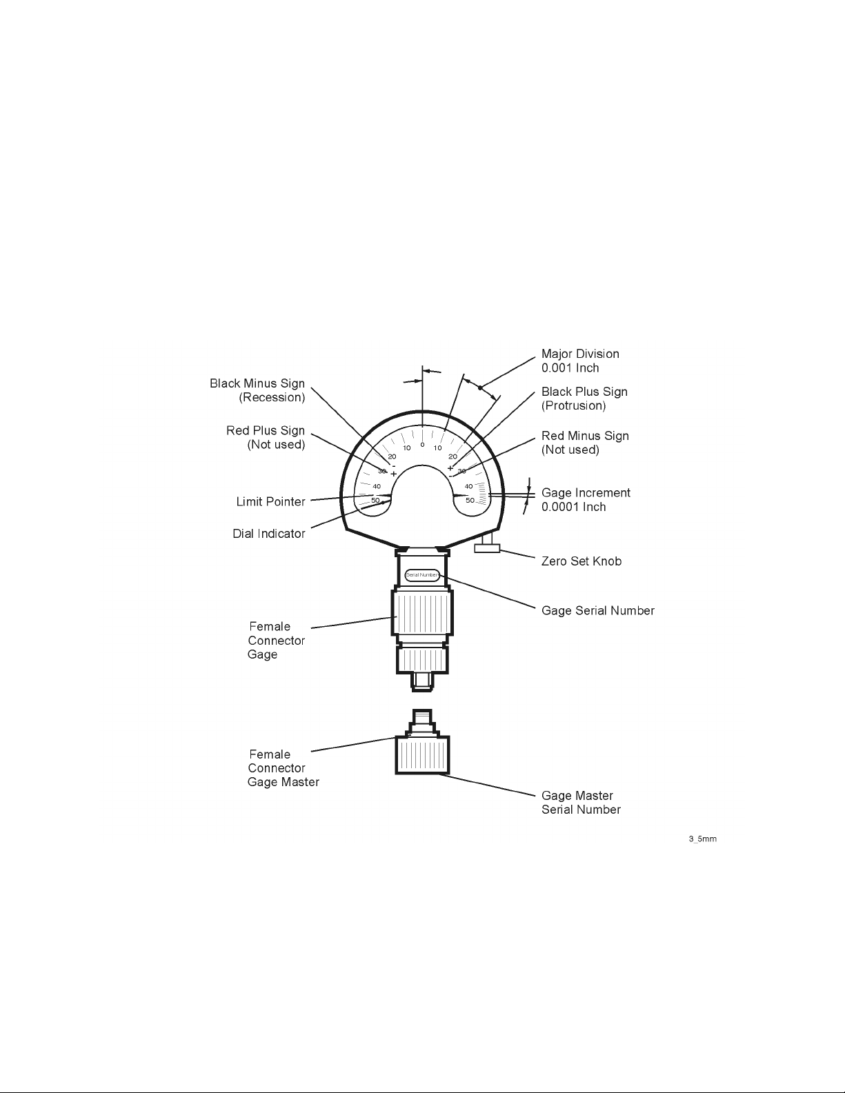
Use, Maintenance, and Care of the Devices
Gaging Connectors
When making a measurement, the gage dial indicator will travel in one of two
directions. If the center conductor is recessed from the zero reference plane,
the indicator will move counterclockwise to determine the amount of
recession, which is read as a negative value. If center conductor protrudes, the
indicator will move clockwise to measure the amount of protrusion, which is
read as a positive value. Refer to “Typical Pin Depth Values” on page 5-26 for
definitions of protrusion and recession.
Figure 4-3 Typical Gage: 1.85 mm, 2.4 mm, 2.92 mm, and 3.5 mm Connectors
Electronic Calibration Modules Reference Guide 4-11
Page 94
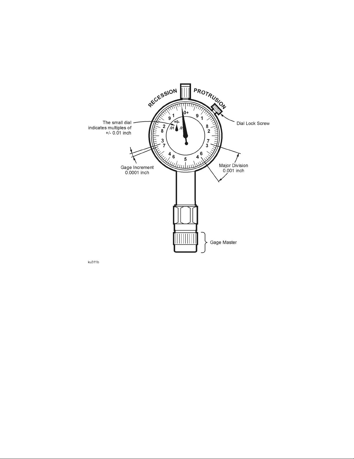
4-
Use, Maintenance, and Care of the Devices
Gaging Connectors
Figu re 4-4 Typical Gage: Type-N Connectors
4-12 Electronic Calibration Modules Reference Guide
Page 95
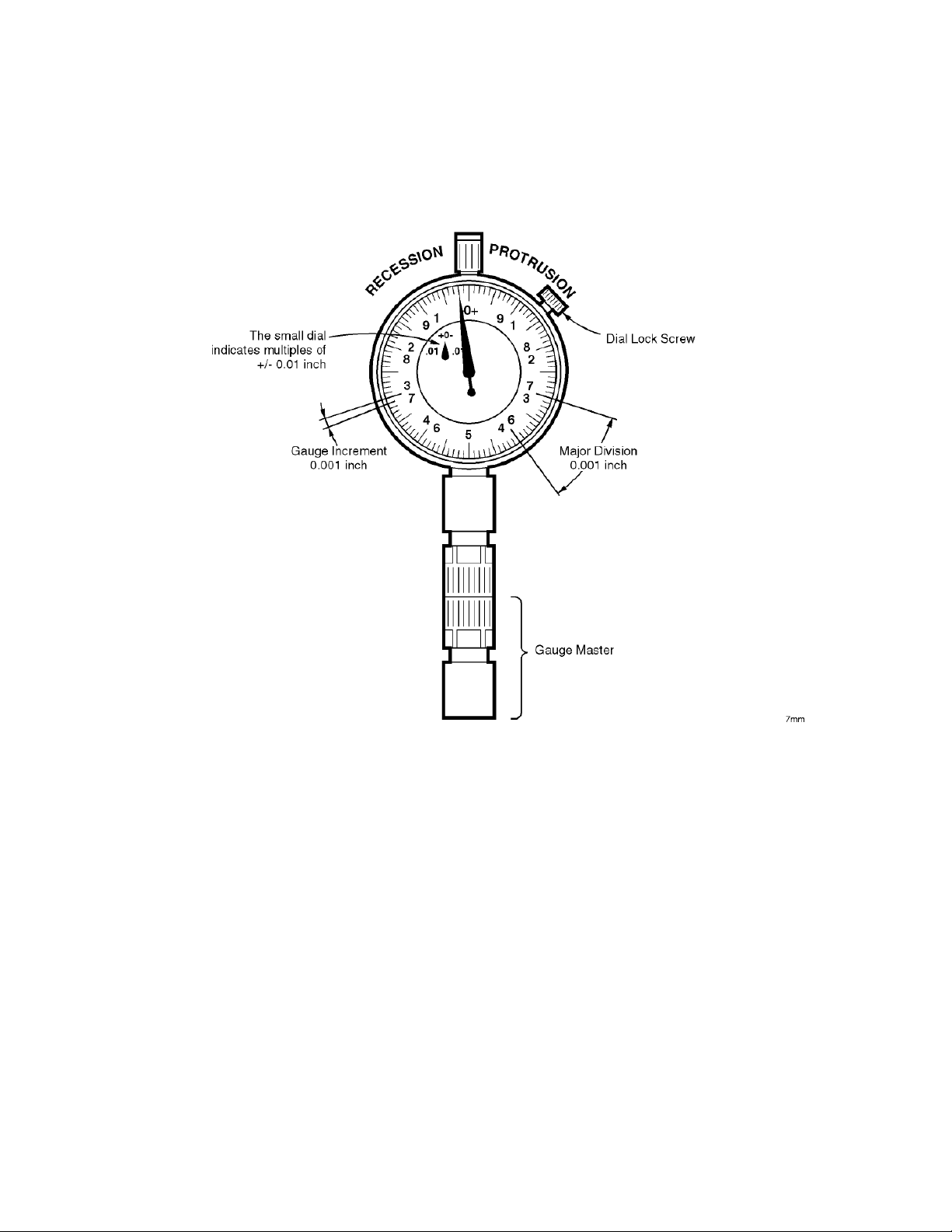
Use, Maintenance, and Care of the Devices
Gaging Connectors
Figure 4-5 Typical Gage: 7 mm Connectors
Electronic Calibration Modules Reference Guide 4-13
Page 96

4-
Use, Maintenance, and Care of the Devices
Gaging Connectors
Gaging Procedures
For 7 mm connectors, you must remove the collet with the collet extractor
tool prior to performing pin depth measurements.
Zeroing Connector Gages
For Type-N gages, the paired gage master is labeled with an offset value to
compensate for its inaccuracy with its gage. This label appears on the bottom
of all Type-N gage masters that have been paired with gages. When setting a
Type-N gage with its master, always set the gage to the master offset value
shown on the label, not to the zero, unless that is the offset value indicated.
The design of the gages used to measure 3.5 mm, 2.92 mm, 2.4 mm, and
1.85 mm connectors are different than the Type-N gage design. The primary
difference is that the Type-N gages require an offset to compensate for
inaccuracies in the gage masters.
1. Select the proper gage for your connector. Always use gages that are
intended for pin depth measurements. Refer to Chapter 6, “Replaceable
Parts.” for gage model numbers listed with the associated connector
types.
2. Inspect and clean the gage, gage master, and device to be gaged. Refer to
“Visual Inspection” on page 4-3 and “Cleaning Connectors” on page 4-6.
Before continuing, make sure you are familiar with the proper connection
and torque techniques for your connector type. Refer to “Making
Connections” on page 4-17.
3. While holding the gage by the barrel, attach the gage to the gage master.
Connect the gage master finger tight. Do not overtighten.
4. Use the torque wrench recommended for use with your connector type to
tighten the connecting nut to the gage master. Refer to Table 4-1 on
page 4-21.
5. Type-N: Loosen the dial lock screw on the gage and rotate the gage dial
so that the pointer corresponds to the correction value noted on the gage
master. Do not adjust the gage dial to zero unless the correction value on
the gage master is zero.
1.85/2.4/2.92/3.5/7 mm: The gage pointer should line up exactly with the
zero mark on the gage. If not, adjust the zero set knob or rotate the gage
dial until the gage pointer lines up exactly with zero.
6. Tighten the dial lock screw and remove the gage master.
7. Attach and torque the gage master once again to verify that the setting is
repeatable. Remove the gage master.
4-14 Electronic Calibration Modules Reference Guide
Page 97

Use, Maintenance, and Care of the Devices
Gaging Connectors
Gaging Technique
1. Connect and torque the device being measured to the gage.
2. Gently tap the barrel of the gage with your finger to settle the gage
reading.
3. Type-N and 7 mm: Read the gage indicator dial. If the needle has moved
clockwise, the center conductor is protruding by an amount indicated by
the black numbers. If the needle has moved counterclockwise, the center
conductor is recessed by an amount indicated by the red numbers. For
more on 7 mm connectors, See also, “Gaging Technique–7 mm Gage” on
page 4-16.
1.85/2.4/2.92/3.5 mm: Read the gage indicator dial. Read only the black
± signs; not the red ± signs.
4. For maximum accuracy, measure the connector a minimum of three times
and take an average of the readings. After each measurement, rotate the
gage a quarter-turn to reduce measurement variations that result from the
gage or the connector face not being exactly perpendicular to the center
axis.
5. Compare the average reading with the observed pin depth limits in the
tables located in “Typical Pin Depth Values” on page 5-26 for each type of
connector.
Electronic Calibration Modules Reference Guide 4-15
Page 98
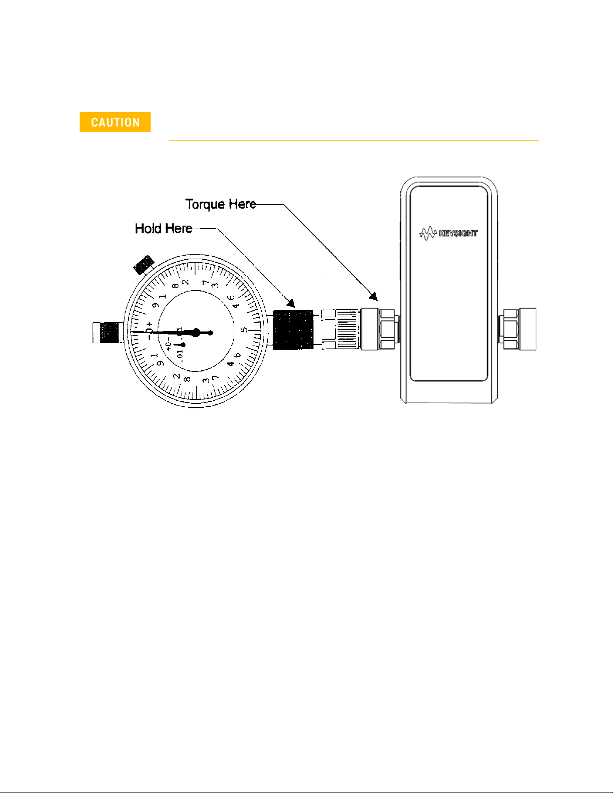
4-
Use, Maintenance, and Care of the Devices
Gaging Connectors
Gaging Technique–7 mm Gage
You must remove the collet with the collet extractor tool prior to
performing pin depth measurements.
Figure 4-6 Using a 7 mm Gage
While performing pin depth measurements, use different orientations of the
gage with the connector. Average a minimum of three readings, each taken
after a quarter-turn rotation of the gage, to reduce measurement variations
that result from the gage or the connector face not being exactly perpendicular
to the center axis.
To zero a gauge, review the instructions in “Zeroing Connector Gages” on
page 4-14.
4-16 Electronic Calibration Modules Reference Guide
Page 99

Use, Maintenance, and Care of the Devices
Making Connections
Making Connections
Good connections are essential for accurate calibrations and measurements
and require a skilled operator. The most common cause of measurement
error is poor connections.
1.85 mm, 3.5 mm, 2.4 mm, 2.92 mm, and Type-N Devices
1. Handle the devices at a static-safe work station, only. See “Electrostatic
Discharge” on page 4-1.
2. Carefully align the connectors. The male connector center pin must slip
concentrically into the contact finger of the female connector.
Do not turn the device body. Only turn the connector nut. Damage to the
center conductor can occur if the device body is twisted.
3. Push the connectors straight together and tighten the connector nut
finger tight. Do not twist or screw the connector together. As the center
conductors mate, there is usually a slight resistance
4. The preliminary connection is tight enough when the mating plane
surfaces make uniform, light contact. Do not overtighten this connection.
A connection in which the outer conductors make gentle contact at all
points on both mating surfaces is sufficient. Very light finger pressure is
enough to accomplish this.
5. Make sure the connectors are properly supported. Relieve any side
pressure on the connection from long or heavy devices or cables.
6. Torque the connection according to the procedures described in “Final
Connection Using a Torque Wrench” on page 4-18.
7 mm Devices
Fully extend the connector sleeve on one of the connectors and fully retract
the sleeve on the other. The extended sleeve creates a cylinder into which the
second connector fits.
If one of the connectors is fixed (as on a test port), fully extend that connector
sleeve (spin its knurled connector nut to make sure the threads are fully
extended). Fully retract the connector sleeve on the other connector.
1. Handle the devices at a static-safe work station, only. See “Electrostatic
Discharge” on page 4-1.
2. Remove the 7 mm collet from the center conductor with the collet
extractor tool.1.Remove the 7 mm collet from the center conductor with
the collet extractor tool.
3. Carefully align the connectors.
Electronic Calibration Modules Reference Guide 4-17
Page 100

4-
Use, Maintenance, and Care of the Devices
Making Connections
4. As you bring one connector up to the other, and as you make the actual
connection, be sure the connectors align perfectly.
5. Push the connectors straight together. Do not twist or screw them
together.
6. Engage the connector nut over the threads on the second connector. Turn
only the connector nut. Let the connector nut pull the two connectors
straight together.
7. Carefully align the connectors. The male connector center pin must slip
concentrically into the contact finger of the female connector.
IMPORTANT! At this point, you want a connection in which the outer
conductors make gentle contact at all points on both mating surfaces. This
requires very light finger pressure.
8. Push the connectors straight together and tighten the connector nut
finger tight. Do not twist or screw the connector together. As the center
conductors mate, there is usually a slight resistance
Final Connection Using a Torque Wrench
Using a torque wrench guarantees the connection is not too tight, preventing
possible connector damage. It also guarantees that all connections are equally
tight.
Use the recommended torque wrench to make a final connection. Table 4-1 on
page 4-21 provides information on the torque wrench recommended for use
with each connector type.
1. Turn the connector nut. This may be possible to do by hand if one of the
connectors is fixed (as on a test port). However, it is recommended that
you use an open-end wrench to keep the body of the device from turning.
2. Position both wrenches within 90 degrees of each other before applying
force. Wrenches opposing each other (greater than 90 degrees apart) will
cause a lifting action that can misalign and stress the connections of the
device involved. This is especially true when several devices are
connected together. Refer to Figure 4-7.
4-18 Electronic Calibration Modules Reference Guide
 Loading...