

Page 1
Keysight N4391B Optical
Modulation Analyzer
Getting Started
Guide
Page 2

Notices
CAUTION
WARNING
© Keysight Technologies 2019
No part of this manual may be reproduced
in any form or by any means (including
electronic storage and retrieval or translation into a foreign language) without prior
agreement and written consent from
Keysight Technologies as governed by
United States and international copyright
laws.
Manual Part Number
N4391-90A02
Edition
Edition 1.0, March 2019
Keysight Technologies Deutschland GmbH
Herrenberger Strasse 130,
71034 Böblingen, Germany
Technology Licenses
The hardware and/or software described in
this document are furnished under a
license and may be used or copied only in
accordance with the terms of such license.
U.S. Government Rights
The Software is “commercial computer
software,” as defined by Federal Acquisition
Regulation (“FAR”) 2.101. Pursuant to FAR
12.212 and 27.405-3 and Department of
Defense FAR Supplement (“DFARS”)
227.7202, the U.S. government acquires
commercial computer software under the
same terms by which the software is
customarily provided to the public.
Accordingly, Keysight provides the Software to U.S. government customers under
its standard commercial license, which is
embodied in its End User License Agreement (EULA), a copy of which can be found
at http://www.keysight.com/find/sweula.
The license set forth in the EULA represents
the exclusive authority by which the U.S.
government may use, modify, distribute, or
disclose the Software. The EULA and the
license set forth therein, does not require
or permit, among other things, that
Keysight: (1) Furnish technical information
related to commercial computer software
or commercial computer software
documentation that is not customarily
provided to the public; or (2) Relinquish to,
or otherwise provide, the government
rights in excess of these rights customarily
provided to the public to use, modify,
reproduce, release, perform, display, or
disclose commercial computer software or
commercial computer software
documentation. No additional government
requirements beyond those set forth in the
EULA shall apply, except to the extent that
those terms, rights, or licenses are
explicitly required from all providers of
commercial computer software pursuant to
the FAR and the DFARS and are set forth
specifically in writing elsewhere in the
EULA. Keysight shall be under no obligation
to update, revise or otherwise modify the
Software. With respect to any technical
data as defined by FAR 2.101, pursuant to
FAR 12.211 and 27.404.2 and DFARS
227.7102, the U.S. government acquires no
greater than Limited Rights as defined in
FAR 27.401 or DFAR 227.7103-5 (c), as
applicable in any technical data.
Warranty
THE MATERIAL CONTAINED IN THIS DOCUMENT IS PROVIDED "AS IS," AND IS
SUBJECT TO BEING CHANGED, WITHOUT
NOTICE, IN FUTURE EDITIONS. FURTHER,
TO THE MAXIMUM EXTENT PERMITTED BY
APPLICABLE LAW, KEYSIGHT DISCLAIMS
ALL WARRANTIES, EITHER EXPRESS OR
IMPLIED WITH REGARD TO THIS MANUAL
AND ANY INFORMATION CONTAINED
HEREIN, INCLUDING BUT NOT LIMITED TO
THE IMPLIED WARRANTIES OF
MERCHANTABILITY AND FITNESS FOR A
PARTICULAR PURPOSE. KEYSIGHT SHALL
NOT BE LIABLE FOR ERRORS OR FOR
INCIDENTAL OR CONSEQUENTIAL
DAMAGES IN CONNECTION WITH THE
FURNISHING, USE, OR PERFORMANCE OF
THIS DOCUMENT OR ANY INFORMATION
CONTAINED HEREIN. SHOULD KEYSIGHT
AND THE USER HAVE A SEPARATE
WRITTEN AGREEMENT WITH WARRANTY
TERMS COVERING THE MATERIAL IN THIS
DOCUMENT THAT CONFLICT WITH THESE
TERMS, THE WARRANTY TERMS IN THE
SEPARATE AGREEMENT WILL CONTROL.
Safety Notices
A CAUTION notice denotes a hazard.
It calls attention to an operating
procedure, practice, or the like that,
if not correctly performed or adhered
to, could result in damage to the
product or loss of important data. Do
not proceed beyond a CAUTION
notice until the indicated conditions
are fully understood and met.
A WARNING notice denotes a hazard.
It calls attention to an operating
procedure, practice, or the like that,
if not correctly performed or adhered
to, could result in personal injury or
death. Do not proceed beyond a
WARNING notice until the indicated
conditions are fully understood and
met.
2 Keysight N4391B Optical Modulation Analyzer Getting Started Guide
Page 3

Safety Summary
General This product is a Safety Class 1 instrument (provided with a protective earth terminal).
The following general safety precautions must be observed during all phases of operation
of this instrument. Failure to comply with these precautions or with specific warnings or
operating instructions in the product manuals violates safety standards of design,
manufacture, and intended use of the instrument. Keysight Technologies assumes no
liability for the customer's failure to comply with these requirements. Product manuals
are provided with your instrument on CD-ROM and/or in printed form. Printed manuals
are an option for many products. Manuals may also be available on the Web. Go to
www.keysight.com and type in your product number in the Search field at the top of the
page.
The protective features of this product may be impaired if it is used in a manner not
specified in the operation instructions.
All Light Emitting Diodes (LEDs) used in this product are Class 1 LEDs as per IEC
60825-1.
Environment Conditions
Before Applying Power
Ground the Instrument
Do Not Operate in an
Explosive Atmosphere
Do Not Remove the
Instrument Cover
This instrument is intended for indoor use in an installation category II, pollution degree 2
environment. It is designed to operate at a maximum relative humidity of 80% and at
altitudes of up to 2000 meters.
Refer to the specifications tables for the ac mains voltage requirements and ambient
operating temperature range.
Verify that all safety precautions are taken. The power cable inlet of the instrument serves
as a device to disconnect from the mains in case of hazard. The instrument must be
positioned so that the operator can easily access the power cable inlet. When the
instrument is rack mounted the rack must be provided with an easily accessible mains
switch.
To minimize shock hazard, the instrument chassis and cover must be connected to an
electrical protective earth ground. The instrument must be connected to the ac power
mains through a grounded power cable, with the ground wire firmly connected to an
electrical ground (safety ground) at the power outlet. Any interruption of the protective
(grounding) conductor or disconnection of the protective earth terminal will cause a
potential shock hazard that could result in personal injury.
Do not operate the instrument in the presence of flammable gases or fumes.
Operating personnel must not remove instrument covers. Component replacement and
internal adjustments must be made only by qualified personnel.
Instruments that appear damaged or defective should be made inoperative and secured
against unintended operation until they can be repaired by qualified service personnel.
Keysight N4391B Optical Modulation Analyzer Getting Started Guide 3
Page 4
Compliance and Environmental Information
Table 1 Compliance and Environmental Information
Safety Symbol Description
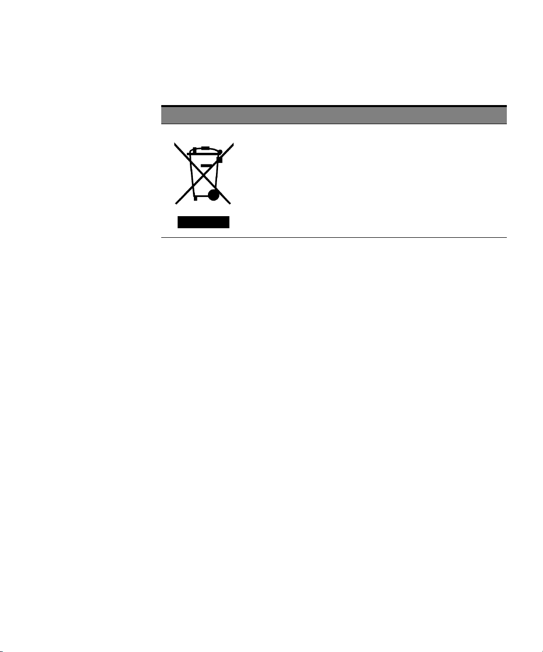
This product complies with WEEE Directive (2002/96/EC) marking requirements.
The affixed label indicates that you must not discard this electrical/electronic
product in domestic household waste.
Product Category: With reference to the equipment types in WEEE Directive Annex I,
this product is classed as a “Monitoring and Control instrumentation” product.
Do not dispose in domestic household waste.
To return unwanted products, contact your local Keysight office, or see
www.keysight.com/environment/product/ for more information.
4 Keysight N4391B Optical Modulation Analyzer Getting Started Guide
Page 5

Contents
1 Introduction
Safety Summary 3
Compliance and Environmental Information 4
Documentation 8
N4391B Documentation 8
Instructions for use 8
General Safety Considerations 9
Intended use 9
Safety symbols 9
Instrument markings 9
Initial Safety Information 12
Line power requirements 14
Environmental Information 15
N4391B Shipping Contents 16
2 Getting Started
N4391B Optical Modulation Analyzer Setup 20
Introduction 20
Integrating the UXRXXX4A High-Performance Oscilloscope 20
Connecting the System 27
Using the correct connectors 27
Enabling and disabling the laser output 28
Keysight N4391B Optical Modulation Analyzer Getting Started Guide 5
Page 6

Contents
Creating Your First Trace on the OMA 29
Installing Software Components 33
Downloading the Photonic Application Suite Package
Manager
Installing the Keysight N439xA Software 36
3 Returning the Instrument for Maintenance
Returning the Instrument 37
4 Rack Mount
Rack Mounting the N4391B 40
5 Regulatory Information
Declaration of Conformity 46
Compliance with German Noise Requirements 46
34
6 Keysight N4391B Optical Modulation Analyzer Getting Started Guide
Compliance with Canadian EMC Requirements 46
Page 7

Keysight N4391B Optical Modulation Analyzer
Getting Started Guide
1 Introduction
Documentation / 8
General Safety Considerations / 9
N4391B Shipping Contents / 16
Page 8

1 Introduction
Documentation
N4391B Documentation
The documentation for the Keysight N4391B Optical Modulation Analyzer
consists of
• The documentation for the Keysight UXR-Series oscilloscope. This
documentation is supplied with the oscilloscope, including extensive
online help. Refer to it for using the UXR-Series oscilloscope for
modulation measurements, or for configuring the oscilloscope.
• The documentation for the optical modulation analyzer and the
software application.
This consists of
• This booklet, which contains the information you need to get your
Optical Modulation Analyzer running, and to perform a first
measurement.
• The online help, which provides the instructions for use.
• The online help for the 89601B vector signal analysis software.
Instructions for use
For further information, please refer to the online help.
You can refer to the online help for the Optical Modulation Analyzer by
selecting “Help/Show OMA Help” in the 89600 VSA software interface.
8 Keysight N4391B Optical Modulation Analyzer Getting Started Guide
Page 9
General Safety Considerations
CAUTION
WARNING
Intended use
Safety symbols
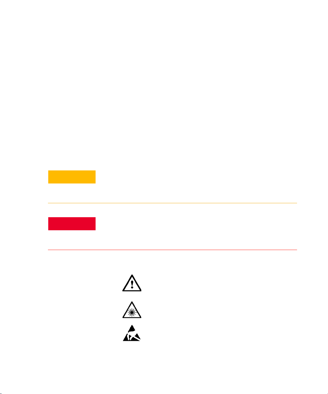
The caution sign denotes a hazard. It calls attention to a procedure which, if not
correctly performed or adhered to, could result in damage to or destruction of
the product. Do not proceed beyond a caution sign until the indicated conditions
are fully understood and met.
Introduction 1
This product has been designed and tested in accordance with the
standards listed on the manufacturer’s Declaration of Conformity (see
Declaration of Conformity on page 46), and has been supplied in a safe
condition. The documentation contains information and warnings that
must be followed by the user to ensure safe operation and to maintain the
product in a safe condition.
This instrument is intended to use in an office or laboratory environment,
under the environmental conditions listed in the specifications.
The warning sign denotes a hazard. It calls attention to a procedure which, if not
correctly performed or adhered to, could result in injury or loss of life. Do not
proceed beyond a warning sign until the indicated conditions are fully
understood and met.
Instrument markings
The instruction manual symbol. The product is marked with
this warning symbol when it is necessary for the user to refer
to the instructions in the manual.
The laser radiation symbol. This warning symbol is marked on
products which have a laser output.
The electrostatic discharge symbol. This warning symbol is
marked on products which have components that can be
damaged by an electrostatic discharge.
Keysight N4391B Optical Modulation Analyzer Getting Started Guide 9
Page 10
1 Introduction
WARNING
WARNING
WARNING
WARNING
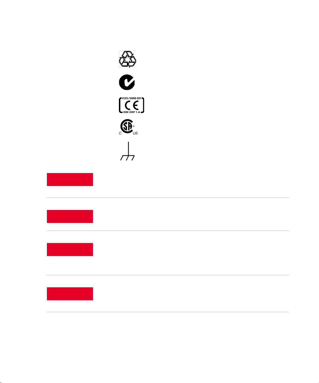
The recycling symbol indicates the general ease with which
the instrument can be recycled.
The C-Tick mark is the certification mark of the Australian
Communications Authority.
The CE mark is the conformity marking of the European
Community.
The CSA mark is the certification mark of the Canadian
Standards Association.
The earthing symbol marks a connection that is connected,
through the instrument, to the earth of the line power.
If this product is not used as specified, the protection provided by the equipment
could be impaired. This product must be used in a normal condition (in which all
means for protection are intact) only.
10 Keysight N4391B Optical Modulation Analyzer Getting Started Guide
No operator serviceable parts inside. Refer servicing to qualified service
personnel. To prevent electrical shock do not remove covers.
This is a Safety Class 1 Product (provided with protective earth). The mains plug
shall only be inserted in a socket outlet provided with a protective earth contact.
Any interruption of the protective conductor inside or outside of the instrument
is likely to make the instrument dangerous. Intentional interruption is prohibited.
To prevent electrical shock, disconnect the instrument from mains before
cleaning. Use a dry cloth or one slightly dampened with water to clean the
external case parts. Do not attempt to clean internally.
Page 11

Introduction 1
WARNING
CAUTION
CAUTION
CAUTION
CAUTION
CAUTION
Using controls or adjustments or performing procedures other than those
specified in the documentation supplied with your equipment can result in
hazardous radiation exposure.
This product complies with over-voltage Category II and Pollution Degree 2.
Ventilation requirements: When installing the product in a cabinet, the
convection into and out of the product must not be restricted. The ambient
temperature (outside the cabinet) must be less than the maximum operating
temperature of the product by 4 °C for every 100 watts dissipated in the cabinet.
If the total power dissipated in the cabinet is greater than 800 watts, then forced
convection must be used.
Install the instrument so that the power cords are readily identifiable and is
easily reached by the operator. This is how the instruments are disconnected.
They disconnect the mains circuit from the mains supply before other parts of
the instrument.
Alternatively, an externally installed switch or circuit breaker (which is readily
identifiable and is easily reached by the operator) may be used as a
disconnecting device.
Keysight N4391B Optical Modulation Analyzer Getting Started Guide 11
Always use the three-prong AC power cords supplied with this instrument.
Failure to ensure adequate earth grounding by not using these cords may cause
instrument damage.
This instrument has autoranging line voltage input. Be sure the supply voltage is
within the specified range.
Page 12
1 Introduction
Initial Safety Information
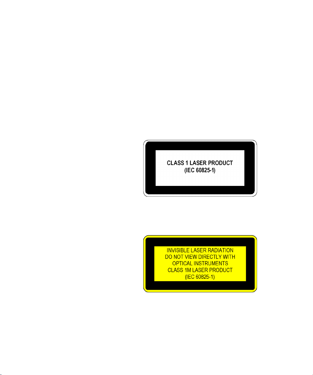
The laser sources classified by this guide are classified as Class 1M
according to IEC 60825-1.
All laser sources comply with 21 CFR 1040.10 except for deviations
pursuant to Laser Notice No. 50, dated 2007-June-24.
Laser Safety
Laser class 1M label (not applied to the product)
Laser class 1M label
A sheet of laser safety labels is included. In order to meet the requirements
of IEC 60825-1 we recommend that you stick the laser safety labels, in
your language, onto a suitable location on the outside of the instrument
where they are clearly visible to anyone using the instrument
12 Keysight N4391B Optical Modulation Analyzer Getting Started Guide
Page 13

Introduction 1
WARNING
N4391B
Laser wavelength range 1528 nm to 1630 nm
Laser Type Booster Optical Amplifier
Laser Class according to IEC 60825-1 1M
Maximum CW output power of the Optical Modulation Analyzer*
Maximum permissible CW output power 163 mW
Numerical aperture 0.1
Beam waist diameter < 10 μm
* CW output power is defined as the highest possible optical output power that the
laser source can produce at the output connector
† For power levels at “LOInput” ≤ 20 dBm
†
< 100 mW
Please pay attention to the following laser safety warnings:
• Under no circumstances look into the end of an optical cable attached to the
optical output when the device is operational. The laser radiation can
seriously damage your eyesight.
• Do not enable the laser when there is no fiber attached to the optical output
connector.
• The laser is enabled by the software. The laser is on when the green LED
above the LO Output connector is lit.
• The use of the instruments, such as microscopes or spectacles, with this
product will increase the hazard to your eyes.
• The laser module has built-in safety circuitry which will disable the optical
output in the case of a fault condition.
• Refer servicing only to qualified and authorized personnel.
Keysight N4391B Optical Modulation Analyzer Getting Started Guide 13
Page 14

1 Introduction
CAUTION
WARNING
Line power requirements
The optical receiver complies with overvoltage category II and pollution degree
2. It can operate from the single-phase AC power source that supplies between
100 V and 240 V (max. voltage fluctuation 10%) at a frequency in the range of 50
to 60 Hz. The maximum power consumption of the optical receiver is 300 VA.
Please refer to the documentation for your UXR-Series oscilloscope for
information on its line power requirements.
Line power connectors
In accordance with international safety standards, the instrument has a
three-wire power cable. When connected to an appropriate AC power
receptacle, this cable earths the instrument cabinet. The type of power
cable shipped with each instrument depends on the country of destination.
To avoid the possibility of injury or death, you must observe the following
precautions before switching on the instrument.
• Insert the power cable plug only into a socket outlet provided with a
protective earth contact. Do not use an extension cord without a protective
conductor. Using an extension cord without a protective conductor means
the instrument is not earthed.
• Do not interrupt the protective earth connection intentionally.
• Do not remove protective covers. Operating personnel must not remove
instrument covers. Component replacement and internal adjustments must
be made only by qualified service personnel.
• Instruments that appear damaged or defective should be made inoperative
and secured against unintended operation until they can be repaired by
qualified service personnel.
• Defective, damaged, or malfunctioning instruments must be returned to an
Keysight Technologies Service Center.
• Do not operate the instrument in the presence of flammable gases or fumes.
Operation of any electrical instrument in such an environment constitutes a
definite safety hazard.
14 Keysight N4391B Optical Modulation Analyzer Getting Started Guide
Page 15

Environmental Information
This product is intended for indoor use only.
This product complies with the WEEE Directive (2002/96/EC) marking
requirements. The affixed label indicates that you must not discard this
electrical/electronic product in domestic household waste.
Product Category: With reference to the equipment types in the WEEE
Directive Annex I, this product is classed as a “Monitoring and Control
instrumentation” product.
Do not dispose in domestic household waste.
To return unwanted products, contact your local Keysight office, or see
www.keysight.com/environment/product/
Introduction 1
for more information.
Keysight N4391B Optical Modulation Analyzer Getting Started Guide 15
Page 16

1 Introduction
N4391B Shipping Contents
Contents for all options
Qty Part number Description
1 0960-2929 OEM Mini Keyboard 319X157X20-mm
1 0960-3246 Optical Mouse USB 2-Buttons 1-Scroll Wheel
1 5061-5311 Connector Assembly - 3.5mm Female to Female
1 54919-92006 Tips for Preventing Damage to Oscilloscopes
1 54964-92007 Pre-Power-On Safety Notes
Unpack your shipment.
• Inspect the shipping containers for damage.
• Inspect the instruments.
• Verify that you received the options and accessories that you ordered.
Keep the shipping containers and cushioning material until you have
inspected the contents of the shipment for completeness and have
checked the equipment mechanically and electrically.
1 5972-3312 ESD Warning Sticker Sheet
2 9300-1308 Heel ground strap
1 9300-1484 ESD MAT Cord
1 9320-6678 China RoHS Addendum for Oscilloscope
1 9320-6797 Keysight safety leaflet
3 08154-61723 Connector Adapter FC
1 5962-0476 Calibration certificate
1 5962-5955 Test Data Sheet
1 5967-7169 Envelope-Entitlement Certificate (241.3 mm X 317.5 mm)
1 8121-1695 Cable-Assembly USB-Plug A TO B 4-COND 500 mm
1 9230-0333 Envelope-calibration certificate (241.3 mm x 317.5 mm)
1 9320-6654 China RoHS Addendum for Photonic Test and Measurement Products
1 N4373-90159 Virus Information Sheet
16 Keysight N4391B Optical Modulation Analyzer Getting Started Guide
Page 17

1 N4391-00232 Cover Front
1 N4391-61032 Assembly Rear Foot Right
1 N4391-00433 Interface Bracket Front
1 N4391-00432 Interface Bracket Right
1 N4391-61031 Assembly Rear Foot Left
1 N4391-00431 Interface Bracket Left
Introduction 1
17 0515-2044 Screw-Machine with Patch-LK 90-DEG-Flat-HD Torx-T20 M4X0.7
10-mm-LG SST-300 Passivated
4 0515-1402 Screw-Machine W/Patch-LK Pan-HD TORX-T15 M3.5X0.6 8 mm-LG
SST-302 Passivated
4 0515-0433 Screw-Machine W/Crest-Cup-Con-Washer Pan-HD Torx-T20 M4X0.7
8 mm-LG SST-300 Passivated
Instrument with 1.85 mm connectors
Qty Part number Description
1 1250-3782 Adapter-Coaxial Straight 2.92 mm Jack 2.40 mm Jack 50-Ohm 40 GHz
2 54932-68712 Adaptor Assembly- 1.85 Female-Female-kit of 2
1 8710-1765 Wrench - Torque 8lb-in, 5/16 Inch
1 N4391-61667 RF Cable Kit 70 G
1 N4391-60123 Assembly Testhead 70 G
1 UXRXXXXX Scope Bandwidth under 80 GHz
Keysight N4391B Optical Modulation Analyzer Getting Started Guide 17
Page 18

1 Introduction
Instrument with 1 mm connectors
Qty Part number Description
1 54964-03801 Wrench - 2 mm thick, dual-ended, fits 6 mm and 7 mm
1 8710-2812 Wrench-Torque 4-in-lb 6 mm-open end Gold-Handle
1 8710-2819 Wrench-Torque Special Double-end 14 mm-open end 4 and 10-in-lb
1 N4391-61668 RF Cable Kit 100 G
1 N4391-60124 Assembly Testhead 110 G
1 UXRXXXXX Scope Bandwidth 80 to 110 GHz or 59 AP
Adapter accessory kit for instrument with 1 mm connectors, option N4391B-801
Qty Part number Description
4 5067-1390 Adapter - 1 mm Ruggedized Female to 1 mm Female
4 5067-1392 Adapter - 1 mm Ruggedized Female to 1.85 mm Female
4 5067-1393 Adapter - 1 mm Ruggedized Female to 2.92 mm Female
Rack mount kit for N4391B Optical Modulation Analyzer, option N4391B-RK1
Qty Part number Description
1 1CM104A 132.6H Rack Mount Kit without Handles, Phantom Gray
1 E3663AC Rail Standard (2 Pieces with Mounting Material)
1 N4391-24104 Trim Plate with Mounting Points for Cable Cover
1 N2156-60001 Rack Mount Kit for UXR Scopes
If anything is missing or defective, contact your nearest Keysight
Technologies sales office. If the shipment was damaged, contact the
carrier, then contact the nearest Keysight Technologies sales office.
18 Keysight N4391B Optical Modulation Analyzer Getting Started Guide
Page 19

Keysight N4391B Optical Modulation Analyzer
Getting Started Guide
2 Getting Started
N4391B Optical Modulation Analyzer Setup / 20
Connecting the System / 27
Creating Your First Trace on the OMA / 29
Installing Software Components / 33
Page 20

2 Getting Started
N4391B Optical Modulation Analyzer Setup
Introduction
The Keysight N4391B Optical Modulation Analyzer consists of a coherent
receiver unit and a high-performance oscilloscope. For the instrument to
operate, the receiver unit and the oscilloscope need to be assembled
according to the procedure described in this section.
Integrating the UXRXXX4A High-Performance Oscilloscope
This section describes the integration procedure with an UXRXXX4A
High-Performance Oscilloscope.
1Preparing the Frame
2 Preparing the Oscilloscope
3 Preparing the Coherent Receiver Unit
4 Combining Oscilloscope and Coherent Receiver Unit
5 Finalizing the System
20 Keysight N4391B Optical Modulation Analyzer Getting Started Guide
Page 21
Preparing the Frame
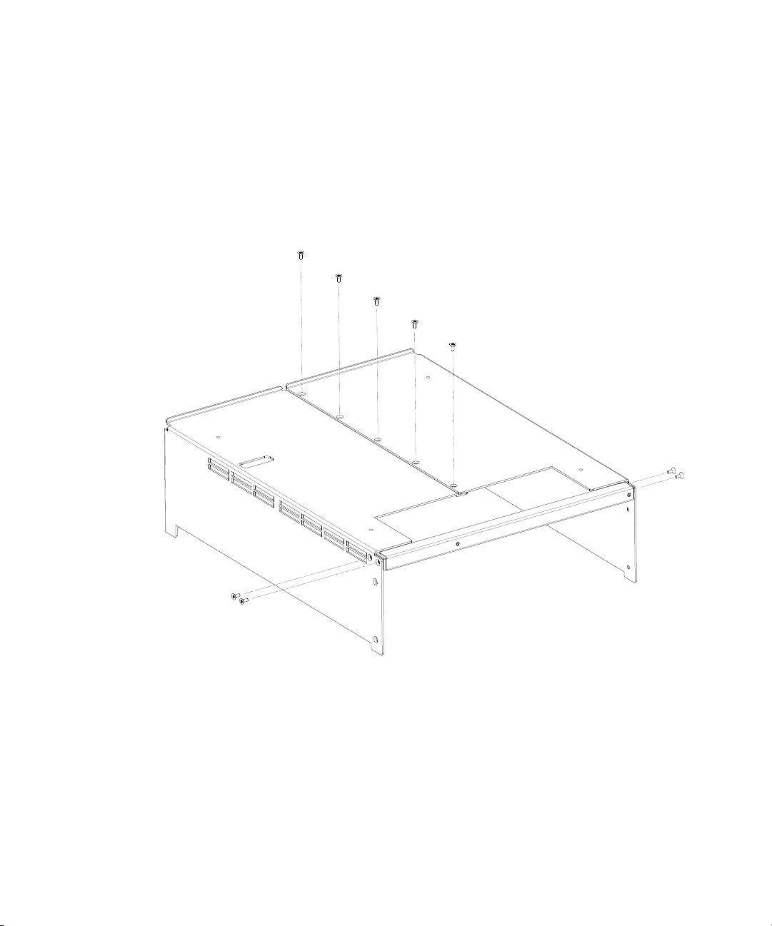
1 According to Figure 1 on page -21, join the left and the right bracket
using a Torx T20 screwdriver and 5 screws: M4x0.7 10mm counter sink,
part number 0515-2044, torque 3 Nm (26-in-lb).
2 Mount the front bracket with 4 additional screws of the same type.
Getting Started 2
Figure 1 Preparing the frame
Keysight N4391B Optical Modulation Analyzer Getting Started Guide 21
Page 22
2 Getting Started
Preparing the Oscilloscope
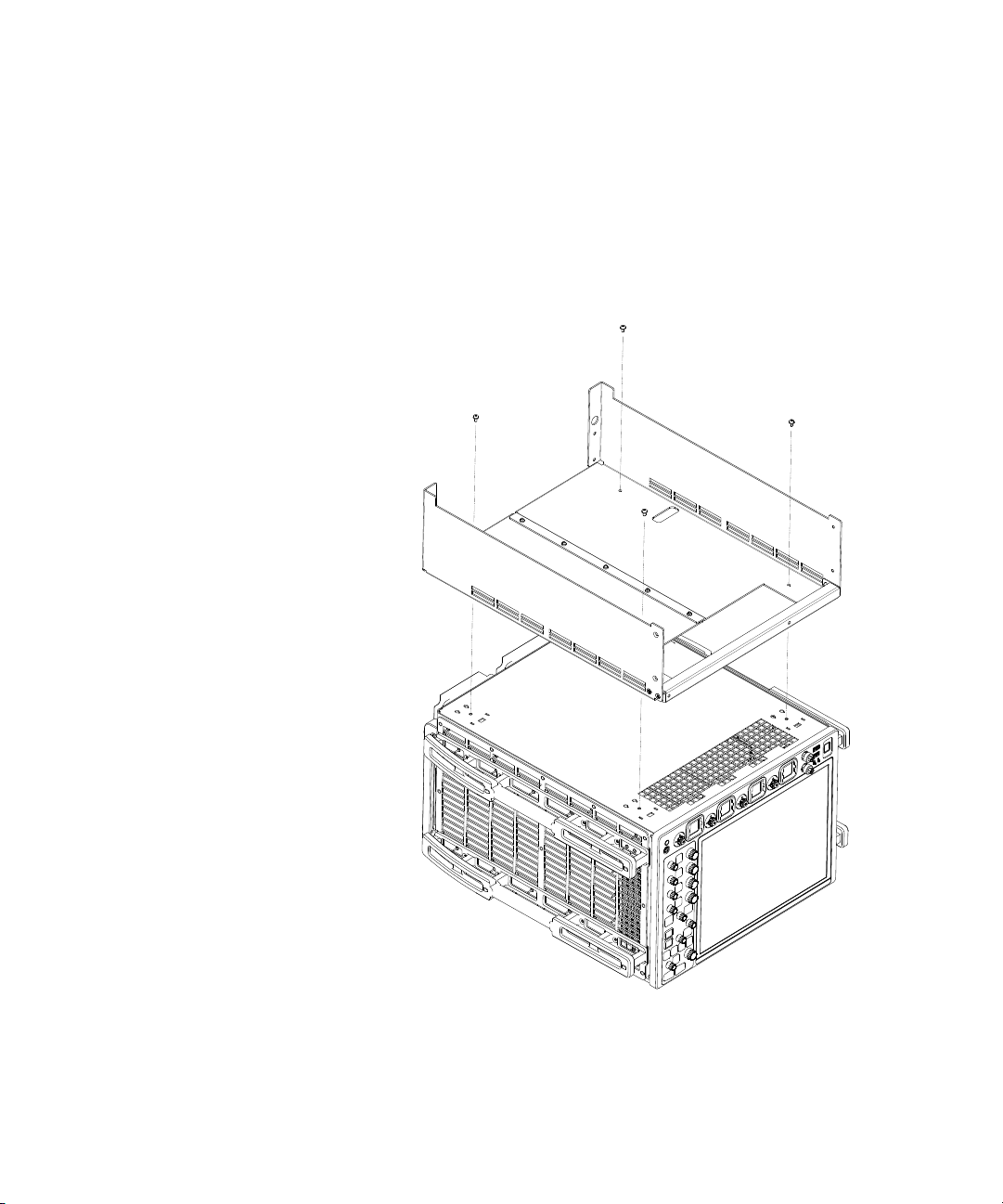
1 Place the oscilloscope upside down on your work surface.
2 Remove the feet from the oscilloscope.
3 Using 4 screws: M4x0.7 8mm, part number 0515-0433, torque 3 Nm
(26-in-lb), attach the frame prepared in step 2.1 to the oscilloscope.
Figure 2 Preparing the oscilloscope
22 Keysight N4391B Optical Modulation Analyzer Getting Started Guide
Page 23
Preparing the Coherent Receiver Unit
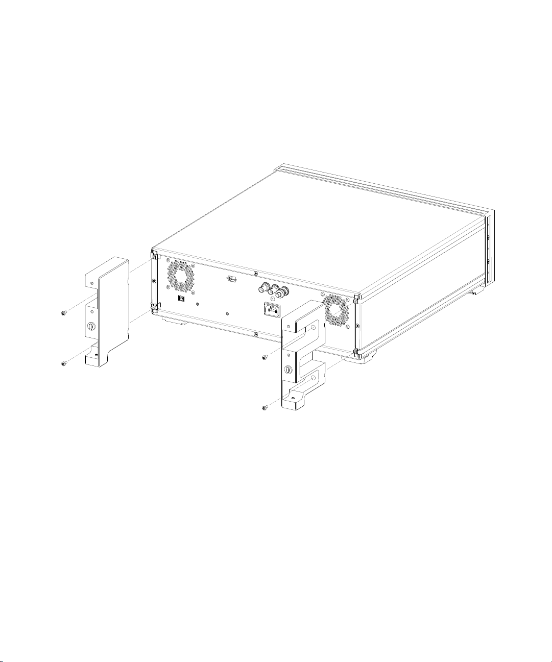
1 a. Mount the left and right foot according to Figure 3 on page -23
using a Torx T15 screw driver and 2 screws: M3.5x0.6 8mm, part
number 0515-1402, torque 2 Nm (17-in-lb), for each foot.
Getting Started 2
Figure 3 Preparing the coherent receiver unit
Keysight N4391B Optical Modulation Analyzer Getting Started Guide 23
Page 24
2 Getting Started
Combining Oscilloscope and Coherent Receiver Unit
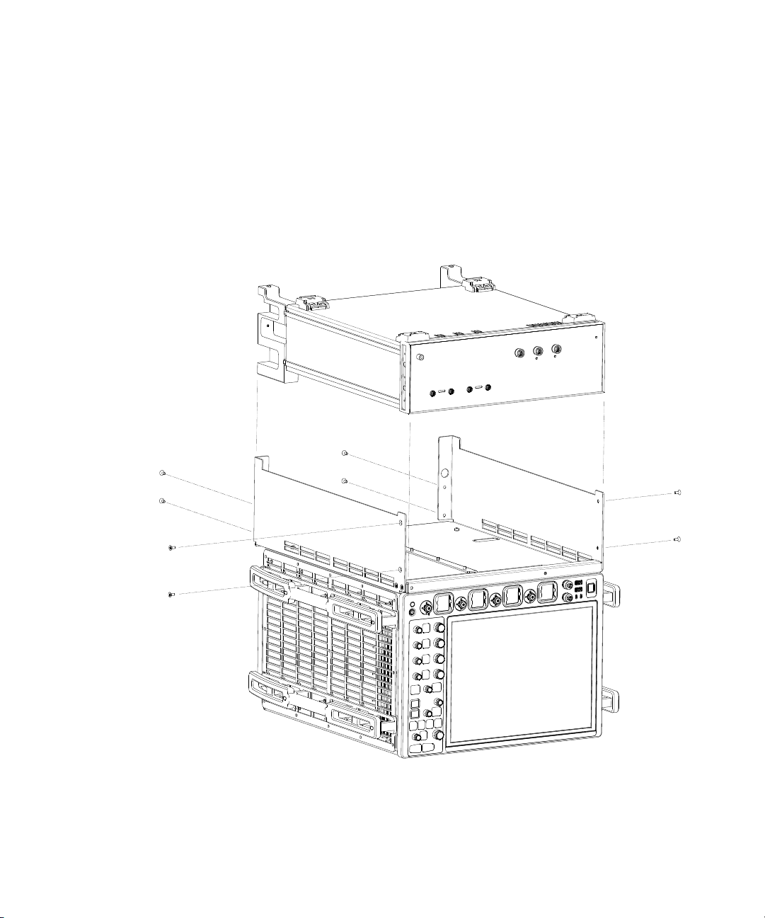
1 Position the coherent receiver unit in between the brackets with the
front flush to the bracket. Insert all 8 screws: M4x0.7 10mm, part
number 0515-2044, torque 3 Nm (26-in-lb), according to Figure 4, but
do not yet tighten them.
2 After all screws are inserted, tighten them completely.
Figure 4 Combining oscilloscope and coherent receiver unit
24 Keysight N4391B Optical Modulation Analyzer Getting Started Guide
Page 25

Finalizing the System
WARNING
CAUTION
Use two persons to lift the system!
The semi-rigid cables are extremely sensitive! Handle them very
carefully!
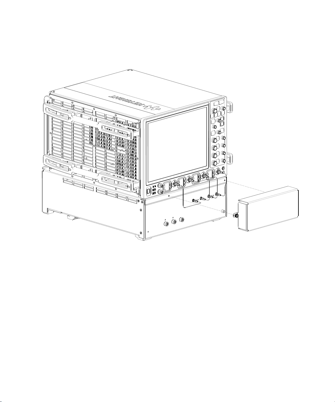
1 Use two persons to turn the system back to upright position.
Do not yet have the semi rigid connector cables installed.
2 Starting from the left, very carefully attach the semi-rigid cables as
shown in Figure 5 on page -26. Tighten with torque wrench, torque
0.4 Nm (4-in-lb).
3 To protect the semi-rigid cables from unintended impact, mount the
protective cover as shown in Figure 5 on page -26.
Getting Started 2
Keysight N4391B Optical Modulation Analyzer Getting Started Guide 25
Page 26
2 Getting Started
Figure 5 Finalizing the system
26 Keysight N4391B Optical Modulation Analyzer Getting Started Guide
Page 27

Connecting the System
CAUTION
CAUTION
Getting Started 2
1 At the rear of the instrument,
a Connect the mouse and keyboard to the oscilloscope.
b Using the USB cable supplied, connect the optical modulation
analyzer to the oscilloscope.
c Using the two power cables supplied, connect the power cables to
the oscilloscope (the power socket with the notch), and the optical
coherent analyzer.
d If necessary, connect your LAN cable to the oscilloscope.
2 Put on the ESD wrist strap and connect it to the ground connector on
the front of the instrument.
3 Remove the protective covers from the connector interfaces on the
front of the instrument and from the patchcord connectors.
4 Connect the optical patchcord.
5 Turn on the instrument, by pressing the power button at the lower left
corner of the front panel.
The maximum input voltage of the UXR-Series oscilloscope is
range-dependent. So to avoid damaging the instrument, make sure to
select a suitable input power range before applying optical power to the
optical modulation analyzer.
Keysight N4391B Optical Modulation Analyzer Getting Started Guide 27
Using the correct connectors
Using the patchcords also keeps service costs down, as the adaptor
patchcord can be exchanged easily.
Angled contact connectors have up to 30dB higher return loss than
straight connectors, and we recommend them for best performance
results. With angled fiber endfaces, reflected light tends to reflect into the
cladding, reducing the amount of light that reflects back to the source.
Always use patchcords to connect to your DUT. This protects the connectors of
the optical modulation analyzer, by minimizing the number of connector
changes.
Page 28

2 Getting Started
CAUTION
CAUTION
The contact connector on the optical modulation analyzer is angled. If you are
using a patchcord with straight and angled connectors, make sure you connect
the angled connector to the optical modulation analyzer.
Connecting to the optical modulation analyzer with a straight connector will
damage it.
Before you connect any fiber-optic cable to the Optical Modulation Analyzer,
please ensure it has been properly cleaned.
Fiber-optic connectors are easily damaged when connected to dirty or damaged
cables and accessories. When you use improper cleaning and handling
techniques, you risk expensive instrument repairs, damaged cables, and
compromised measurements.
Enabling and disabling the laser output
After the Optical Modulation Analyzer application running on the
UXR-Series oscilloscope has initialized it, the green LED above the laser
output indicates whether the laser is emitting radiation.
The laser is enabled and disabled by the software.
28 Keysight N4391B Optical Modulation Analyzer Getting Started Guide
If the Laser output is on, the green LED on the front panel of the module is
lit. If the Laser output is off, the green LED on the front panel of the
module is not lit.
Page 29
Creating Your First Trace on the OMA
The following procedure will familiarize you with the OMA by loading a
recorded demo then using the Smart Setup dialog to ensure that the
parameters are set properly.
The recorded demo is a PRBS 15 dual polarization signal with a
performance that is typically achieved on optical coherent long-haul
transmitters. This signal has incorporated bit errors inserted into the
transmitter PRBS generation.
1 Power on the equipment.
2 Start the Keysight 89600 VSA Software interface by double-clicking on
the Keysight OMA icon ( ).
3 In the Keysight 89600 VSA Software interface, select
File > Recall > Recall Demo.
4In the Recall Demo dialog, open the \Optical Signals\Generic\
DP-QPSK_10.12 GHz_with_errors.htm file.
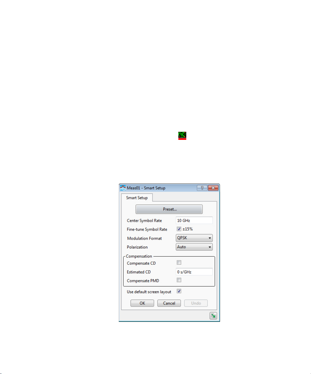
5 Select the Smart Setup menu.
Getting Started 2
Keysight N4391B Optical Modulation Analyzer Getting Started Guide 29
Page 30
2 Getting Started
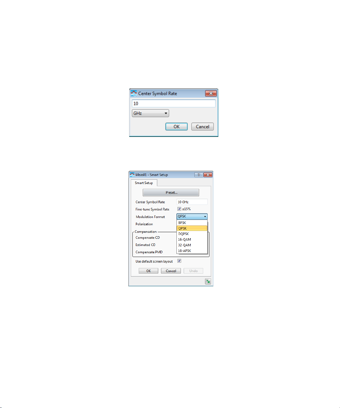
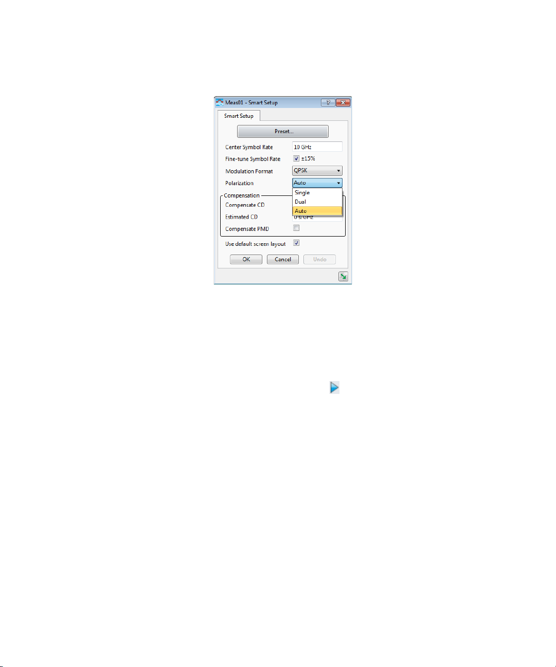
6 Ensure that the Center Symbol Rate is set to 10 GHz. If not,
double-click in the Center Symbol Rate field then enter the value. The
Fine-tune symbol Rate selection ensures that the symbol rate is
adjusted to within the displayed range.
7 Ensure that the Modulation Format is set to QPSK. If not, select it from
the Modulation Format list.
8 Ensure that Polarization is set to Auto. If not, select it from the
Polarization list. Smart Setup will determine the polarization
automatically (single or dual) when set to Auto.
30 Keysight N4391B Optical Modulation Analyzer Getting Started Guide
Page 31
Getting Started 2
9 Ensure that Compensate CD (chromatic dispersion) and Compensate
PMD (polarization mode dispersion) are deselected.
10 Ensure that Use default screen layout is selected to use the default
layout which provides a wide variety of results. If not selected, the
current layout will be used.
11 Click on the OK button.
12 Select the Restart button ( ) in the tool bar to start the
measurement.
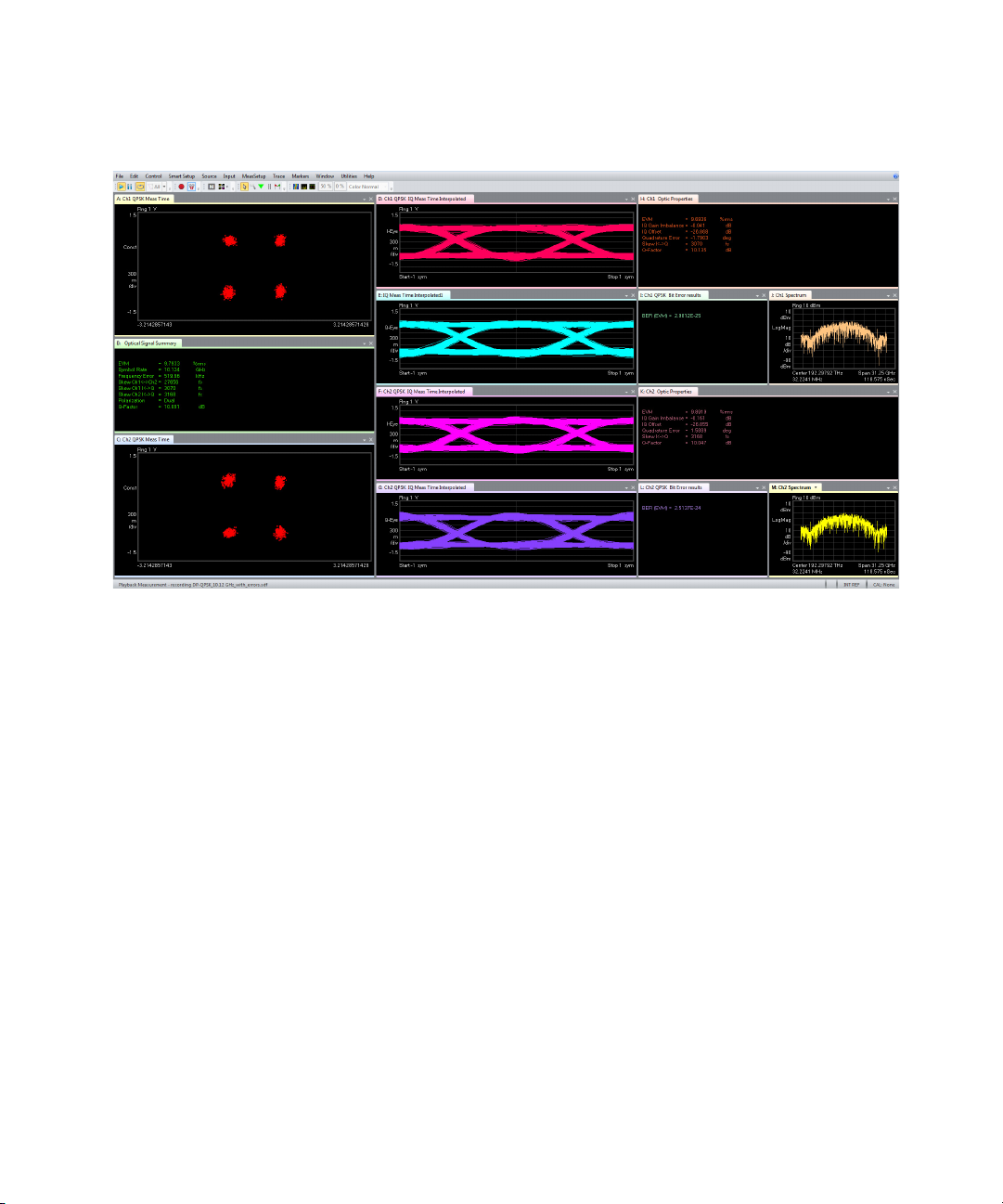
13 You should see results similar to the following.
Keysight N4391B Optical Modulation Analyzer Getting Started Guide 31
Page 32
2 Getting Started
32 Keysight N4391B Optical Modulation Analyzer Getting Started Guide
Page 33
Installing Software Components
All software components are pre-installed at the factory. However, this
section provides installation instructions if it becomes necessary to
reinstall some or all of the software components.
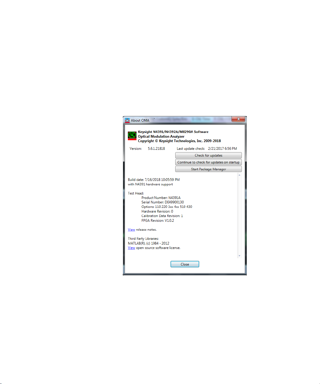
You can search for updates through the VSA interface by selecting Help >
About OMA then clicking on the Check for updates button. Refer to the
following screen.
Getting Started 2
Keysight N4391B Optical Modulation Analyzer Getting Started Guide 33
Page 34
2 Getting Started
Downloading the Photonic Application Suite Package Manager
The Photonic Application Suite (PAS) Package Manager is used to select
and download software packages for proper operation of the OMA.
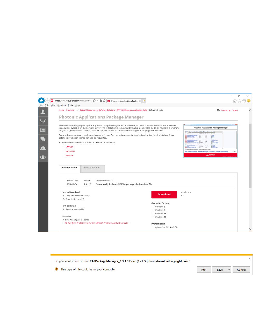
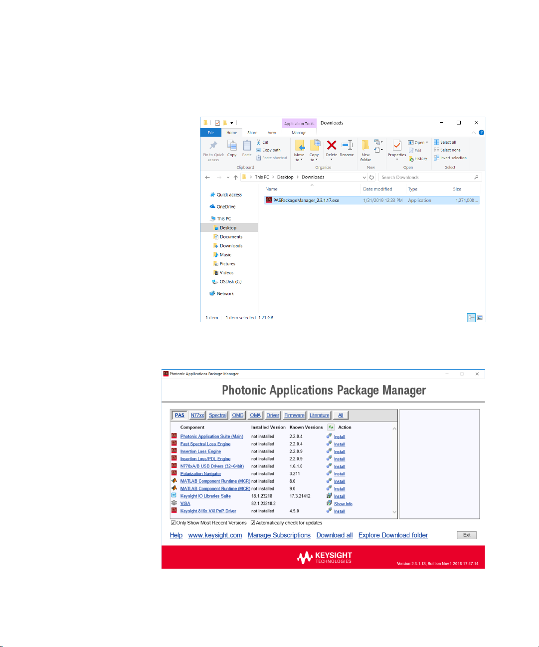
1 Visit the PAS Package Manager web page at
www.keysight.com/find/N7700A, click on the Technical Support link,
select the Drivers, Firmware & Software tab, then click on the
Download button to start the download process.
2Click on the Open button to open the zip file.
34 Keysight N4391B Optical Modulation Analyzer Getting Started Guide
Page 35
Getting Started 2
3 Double-click on the executable file to run the PAS Package Manager.
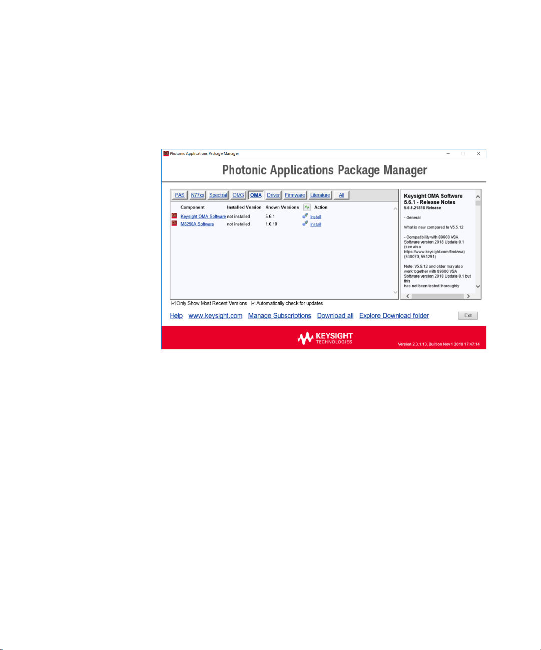
4 Start the PAS Package Manager as administrator and select the OMA
tab to see all possible OMA packages.
Keysight N4391B Optical Modulation Analyzer Getting Started Guide 35
Page 36
2 Getting Started
Installing the Keysight N439xA Software
1 Select the “Keysight N439x Processing Extensions” package which
matches your licensed version.
2Click on the Download link.
3 Continue following the installation instructions and always select the
default settings. The PAS Package Manager will install drivers and
software which are required to install the OMA software. During the
OMA installation itself select your installation type. You can postpone
system restarts until the complete installation is finished.
4 After all installations have been finished, verify that the PAS Package
Manager lists them with an “Installed Version”. If the installations are
not listed, launch the installation of the missing package again. Likely
it was interrupted by a system restart.
36 Keysight N4391B Optical Modulation Analyzer Getting Started Guide
Page 37

3 Returning the
NOTE
Returning the Instrument
Keysight N4391B Optical Modulation Analyzer
Getting Started Guide
Instrument for
Maintenance
Returning the Instrument / 37
If the performance verification fails and you cannot correct the problem,
return the N4391B to Keysight for repair following the steps shown below:
1 Record all symptoms.
2 Contact Keysight at http://www.keysight.com/find/assist.
3 Use the original packing material or comparable packing material to
ship the instrument to Keysight.
The optical receiver and the UXR-Series oscilloscope are two parts of one
instrument.
If you are returning the N4391B to Keysight support, you must return the full
instrument, consisting of both parts.
Page 38

Page 39

Keysight N4391B Optical Modulation Analyzer
Getting Started Guide
4 Rack Mount
Rack Mounting the N4391B / 40
Page 40
4 Rack Mount
Rack Mounting the N4391B
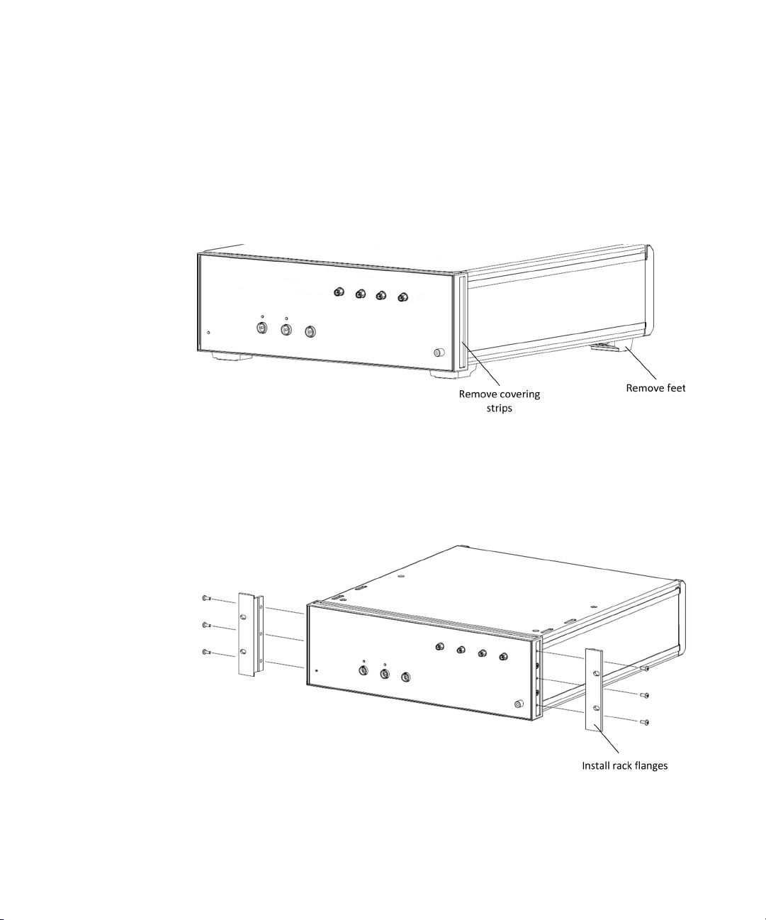
1 Prepare the optical modulation analyzer for rack mounting.
a Remove the four feet from the bottom of the optical modulation
analyzer.
b At the front of the optical modulation analyzer, remove the covering
strips at the left and right edges of the front panel.
c Using parts from the rack mount kit (part number 1CM104A), mount
a rack flange at the left and right of the optical test head.
40 Keysight N4391B Optical Modulation Analyzer Getting Started Guide
Page 41
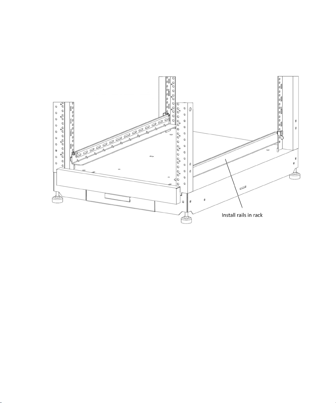
2 Using a Torx T25 screwdriver, mount the rails in the rack.
Rack Mount 4
Keysight N4391B Optical Modulation Analyzer Getting Started Guide 41
Page 42
4 Rack Mount
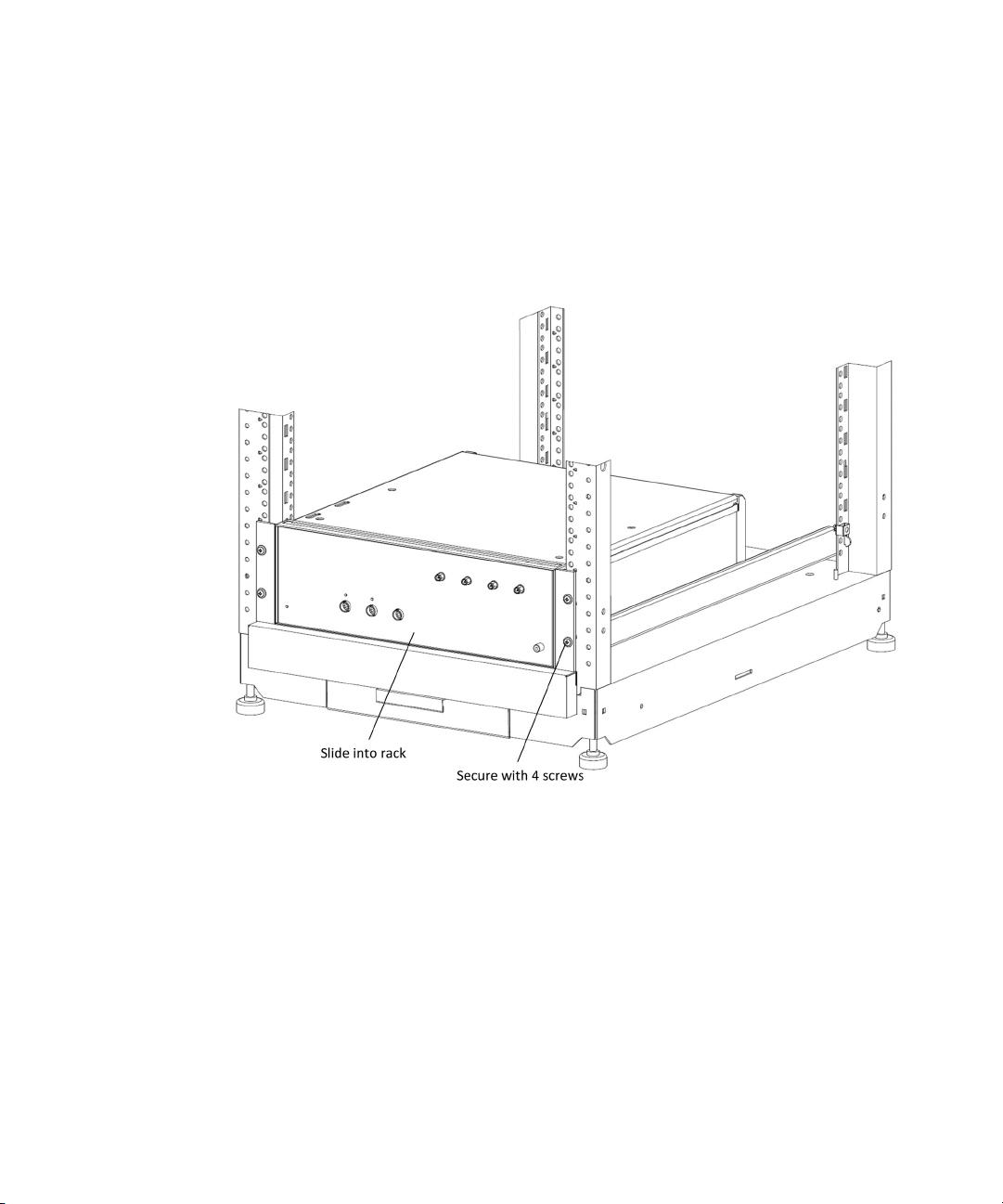
3 Mount the optical modulation analyzer in the rack.
a Slide the optical modulation analyzer onto the rails in the rack.
b Using a cross-recess Phillips screwdriver, and the screws from the
rack mount kit (screw part number 0570-1577), screw the flanges at
the left and right of the optical modulation analyzer to the rack.
4 Swap the bottom trim plate of the UXR-Series Oscilloscope Rack
Mount Kit (N2156-24104) for the one supplied with the N4371B Rack
Mount Kit (N4391-24104).
5 Mount the oscilloscope in the rack according to the procedure in the
UXR-Series Oscilloscope Rack Mount Kit Installation Guide
(N2156-97000). Mount the oscilloscope directly above the optical
modulation analyzer.
42 Keysight N4391B Optical Modulation Analyzer Getting Started Guide
Page 43
Rack Mount 4
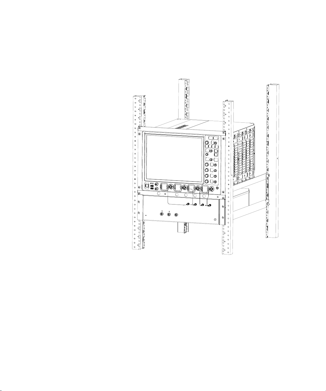
6 Starting from the left, attach the semi-rigid cables very carefully.
Tighten with torque wrench, torque Nm (4-in-lb).
Keysight N4391B Optical Modulation Analyzer Getting Started Guide 43
Page 44
4 Rack Mount
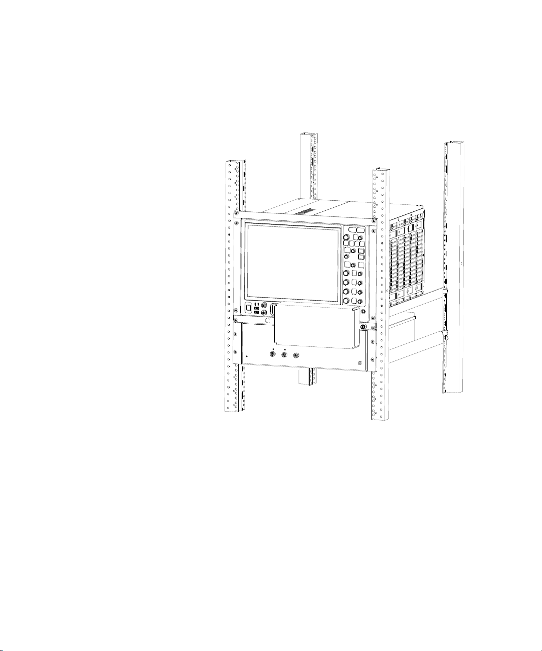
7 To protect the semi-rigid cables from unintended impact, mount the
protective cover.
44 Keysight N4391B Optical Modulation Analyzer Getting Started Guide
Page 45

Keysight N4391B Optical Modulation Analyzer
Getting Started Guide
5 Regulatory
Information
Declaration of Conformity / 46
Compliance with German Noise Requirements / 46
Compliance with Canadian EMC Requirements / 46
Page 46

5 Regulatory Information
Declaration of Conformity
For latest DoC (Declaration of Conformity), please visit the web link:
http://www.keysight.com/go/conformity
Compliance with German Noise Requirements
This is to declare that this instrument is in conformance with the German
Regulation on Noise Declaration for Machines (Lärmangabe nach der
Maschinenlärmverordnung–3.GSGV Deutschland).
Acoustic Noise Emission Geräuschemission
LpA < 70 dB LpA < 70 dB
Operator position am Arbeitsplatz
Normal operation normaler Betrieb
Per ISO 7779/ISO 3744 nach ISO 7779/ISO 3744
Compliance with Canadian EMC Requirements
This ISM device complies with Canadian ICES- 001.
Cet appareil ISM est conforme a la norme NMB-001 du Canada.
46 Keysight N4391B Optical Modulation Analyzer Getting Started Guide
Page 47

Page 48

This information is subject to
change without notice.
© Keysight Technologies 2019
Edition 1.0, March 2019
www.keysight.com
 Loading...