

Page 1

Keysight
N2830/1/2A and N7000/1/2/3A
InfiniiMax III+ Probes
User’s Guide
Page 2

Notices
CAUTION
WARNING
© Keysight Technologies, Inc. 2016, 2017,
2019, 2020
No part of this manual may be reproduced in
any form or by any means (including electronic storage and retrieval or translation
into a foreign language) without prior agreement and written consent from Keysight
Technologies, Inc. as governed by United
States and international copyright laws.
Manual Part Number
N2830-97012
Edition
Thirteenth Edition, November 2020
Published by:
Keysight Technologies, Inc.
1900 Garden of the Gods Road
Colorado Springs, CO 80907 USA
Warranty
The material contained in this document is provided “as is,” and is subject
to being changed, without notice, in
future editions. Further, to the maximum extent permitted by applicable
law, Keysight disclaims all warranties,
either express or implied, with regard
to this manual and any information
contained herein, including but not
limited to the implied warranties of
merchantability and fitness for a particular purpose. Keysight shall not be
liable for errors or for incidental or
consequential damages in connection
with the furnishing, use, or performance of this document or of any information contained herein. Should
Keysight and the user have a separate
written agreement with warranty terms
covering the material in this document
that conflict with these terms, the warranty terms in the separate agreement
shall control.
Technology Licenses
The hardware and/or software
described in this document are furnished under a license and may be
used or copied only in accordance with
the terms of such license.
U.S. Government Rights
The Software is "commercial computer software,"
as defined by Federal Acquisition Regulation
("FAR") 2.101. Pursuant to FAR 12.212 and
27.405-3 and Department of Defense FAR Supplement ("DFARS") 227.7202, the U.S. government acquires commercial computer software
under the same terms by which the software is
customarily provided to the public. Accordingly,
Keysight provides the Software to U.S. government customers under its standard commercial
license, which is embodied in its End User License
Agreement (EULA), a copy of which can be found
at
http://www.keysight.com/find/sweula. The
license set forth in the EULA represents the exclusive authority by which the U.S. government may
use, modify, distribute, or disclose the Software.
The EULA and the license set forth therein, does
not require or permit, among other things, that
Keysight: (1) Furnish technical information related
to commercial computer software or commercial
computer software documentation that is not customarily provided to the public; or (2) Relinquish
to, or otherwise provide, the government rights in
excess of these rights customarily provided to the
public to use, modify, reproduce, release, perform, display, or disclose commercial computer
software or commercial computer software documentation. No additional government requirements beyond those set forth in the EULA shall
apply, except to the extent that those terms,
rights, or licenses are explicitly required from all
providers of commercial computer software pursuant to the FAR and the DFARS and are set forth
specifically in writing elsewhere in the EULA. Keysight shall be under no obligation to update,
revise or otherwise modify the Software. With
respect to any technical data as defined by FAR
2.101, pursuant to FAR 12.211 and 27.404.2 and
DFARS 227.7102, the U.S. government acquires
no greater than Limited Rights as defined in FAR
27.401 or DFAR 227.7103-5 (c), as applicable in
any technical data. 52.227-14 (June 1987) or
DFAR 252.227-7015 (b)(2) (November 1995), as
applicable in any technical data.
Safety Notices
A CAUTION notice denotes a hazard.
It calls attention to an operating
procedure, practice, or the like that,
if not correctly performed or
adhered to, could result in damage
to the product or loss of important
data. Do not proceed beyond a CAU-
TION notice until the indicated conditions are fully understood and
met.
A WARNING notice denotes a hazard. It calls attention to an operating procedure, practice, or the like
that, if not correctly performed or
adhered to, could result in personal
injury or death. Do not proceed
beyond a WARNING notice until the
indicated conditions are fully
understood and met.
Page 3

Contents
1 Using InfiniiMax III+ Series Probes 5
2 Using InfiniiMax III+ Probe Heads 41
Inspecting the Probe and Its Accessories 6
Introduction 9
Compatible Oscilloscopes 15
To Avoid Damaging the Probe 17
To Ensure Maximum Measurement Accuracy 22
To Use InfiniiMode 23
To Probe Ungrounded Devices 26
To Probe Single-Ended Signals with a Differential Head 27
To Measure Small Signals on a Large DC Level 28
Slew Rate Requirements for Different Technologies 31
Available Accessories 33
Safety Information 36
Service 39
Recommended Configurations at a Glance 42
N5444A InfiniiMax III 2.92 mm/3.5 mm/SMA Probe Head 44
N5439A InfiniiMax III ZIF Probe Head 47
N5445A InfiniiMax III Differential Browser Probe Head 53
MX0109A and N2836A InfiniiMode Solder-In Heads 59
N5441A InfiniiMax III Solder-In Head (discontinued) 65
N2848A QuickTip InfiniiMode Probe Head 68
N2835A InfiniiMax III+ Differential Connectivity Kit and Accessories 72
Strain Relieving the Probe Heads 74
Soldering Tips 76
3 Maintaining Probe Heads 77
Replacing Axial Resistor Tips 78
Replacing N5441A Probe Head Wires 82
4 Calibration / Deskew Procedure 87
Procedure 88
3
Page 4

5 Specifications and Characteristics 95
InfiniiMax III+ Warranted Specifications 96
N2830A/1A/2A and N7000/1/2/3A Probe Amplifiers Characteristics 97
N7000A/1A/2A InfiniiMax III+ Probe Heads Characteristics 99
N2830/1/2A InfiniiMax III+ Probe Heads Characteristics 100
Environmental 102
Safety and Regulatory Information 103
Probe Dimensions 104
Probe Heads Dimensions 105
6Performance Plots 109
InfiniiMax III+ Probe System Responses 110
N2848A QuickTip Head with N2849A QuickTip 113
N2836A and MX0109A Solder-In Probe Heads (Flat Orientation) 114
7 Performance Verification for N2830A-Series Probes 117
Bandwidth Performance Verification 118
DC Input Resistance Performance Verification 135
Performance Test Record 137
8 Performance Verification for N7000-Series Probes 139
Bandwidth Performance Verification 140
DC Input Resistance Performance Verification 149
Performance Test Record 151
9SPICE Models 153
N2848A QuickTip Head with N2849A QuickTip Tip 154
N5439A ZIF Probe Head with N5440A ZIF Tip 155
N5439A ZIF Probe Head with N2838A ZIF Tip 156
MX0109A and N2836A 26 GHz Solder-In Probe Heads 157
N5441A 16 GHz Solder-In Probe Head 158
N5445A Browser Probe Head 159
N5444A SMA Probe Head 161
4 InfiniiMax III+ Series Probes User’s Guide
Page 5

Keysight InfiniiMax III+ Series Probes
User’s Guide
1 Using InfiniiMax III+ Series
Probes
Inspecting the Probe and Its Accessories 6
Introduction 9
Compatible Oscilloscopes 15
To Avoid Damaging the Probe 17
To Ensure Maximum Measurement Accuracy 22
To Use InfiniiMode 23
To Probe Ungrounded Devices 26
To Probe Single-Ended Signals with a Differential Head 27
To Measure Small Signals on a Large DC Level 28
Slew Rate Requirements for Different Technologies 31
Available Accessories 33
Safety Information 36
Service 39
This user’s guide covers the N2830/1/2A and N7000/1/2/3A InfiniiMax III+ series
differential probes that are shown in Figure 1.
Figure 1 InfiniiMax III+ Series Probes
5
Page 6

1 Using InfiniiMax III+ Series Probes
Inspecting the Probe and Its Accessories
The N2830/1/2A and N7000/1/2/3A InfiniiMax III+ probes are shipped with a case,
calibration information, probe handling guide, and probe information card that are
shown in Figure 2 on page 7 or Figure 3 on page 8. Most, but not all, of the
shipped items are shown in these figures. After opening the case, lift out the foam
cutout and flip the cutout over to reveal an calibration envelope and a handling
guide.
When you receive your probe, check the following items:
• Inspect the shipping container for damage.
Keep the damaged shipping container or cushioning material until the contents of the
shipment have been checked for completeness and the probe has been checked
mechanically and electrically.
• Check the accessories.
• If the contents are incomplete or damaged, notify your Keysight Technologies
Sales Office.
• Inspect the probe. If there is mechanical damage or defect, or if the probe does
not operate properly or pass calibration tests, notify your Keysight Technologies
Sales Office.
If the shipping container is damaged, or the cushioning materials show signs of
stress, notify the carrier as well as your Keysight Technologies Sales Office. Keep
the shipping materials for the carrier’s inspection. The Keysight Technologies
office will arrange for repair or replacement at Keysight Technologies’ option
without waiting for claim settlement.
6 InfiniiMax III+ Series Probes User’s Guide
Page 7

Using InfiniiMax III+ Series Probes 1
Figure 2 N2830A-Series Probe and Accessories in Supplied Case
InfiniiMax III+ Series Probes User’s Guide 7
Page 8

1 Using InfiniiMax III+ Series Probes
Figure 3 N7000A-Series Probe and Accessories in Supplied Case
8 InfiniiMax III+ Series Probes User’s Guide
Page 9

Introduction
WARNING
CAUTION
Using InfiniiMax III+ Series Probes 1
The InfiniiMax III and III+ Probing System Family Diagram, Figure 4 on page 10,
shows compatible oscilloscopes, probes, and probe heads. The
connect to the oscilloscope using a precision-BNC connection (AutoProbe 1).
N7000/1/2/3A probes connect to the oscilloscope using a 3.5 mm connection (AutoProbe
2).
Figure 5 on page 11 and Figure 6 on page 12 identify most of the probe parts.
N2830/1/2A probes
The
Table 1 Probe Bandwidths
AutoProbe 1 (Precision BNC)
Scope Connection
Probe Bandwidth Probe Bandwidth
N2832A 13 GHz N7003A 20 GHz
N2831A 8 GHz N7002A 16 GHz
N2830A 4 GHz N7001A 13 GHz
N7000A 8 GHz
Both the
InfiniiMax III+ N2830/1/2A and N7000/1/2/3A probes support InfiniiMode
AutoProbe 2 (3.5 mm)
Scope Connection
when using the N2848A QuickTip probe head, MX0109A Extreme Temperature
Solder-in head, N2836A Solder-in head or N5444A 2.92 mm/SMA head.
InfiniiMode allows you to switch between differential, single-ended, and common
mode measurements without needing to change or reconnect the probe or probe
leads. Switching measurements is accomplished using the oscilloscope’s probe
configuration dialog box. For more information, refer to “To Use InfiniiMode" on
page 23.
Before using the probe, refer to “Safety Information" on page 36.
Probe heads
Before you can use the probe, you must connect one of the available probe heads
that are shown in Figure 4 on page 10 and documented in Chapter 2, “Using
InfiniiMax III+ Probe Heads". These probe heads are also compatible with the
InfiniiMax III N2800A-series probes.
Before using the probes, refer to “To Avoid Damaging the Probe" on page 17.
Differential probe heads offer easy measurement of differential signals and greatly
improve the measurement of single-ended signals. Single-ended probe heads
offer extremely small size for probing single-ended signals in confined spaces.
InfiniiMax III+ Series Probes User’s Guide 9
Page 10

1 Using InfiniiMax III+ Series Probes
Figure 4 InfiniiMax III and III+ Family Diagram with Compatible Scopes and Probe Heads
(not to scale)
10 InfiniiMax III+ Series Probes User’s Guide
Page 11

Using InfiniiMax III+ Series Probes 1
Figure 5 N2830/1/2A Probes
InfiniiMax III+ Series Probes User’s Guide 11
Page 12

1 Using InfiniiMax III+ Series Probes
Figure 6 N7000/1/2/3A Probes
12 InfiniiMax III+ Series Probes User’s Guide
Page 13

AutoProbe Interface Connectors
Figure 7 and Figure 8 show the AutoProbe interface connectors that connect the
probes to the oscilloscope. The N2830/1/2A probes use the AutoProbe I interface
which connects to precision BNC oscilloscope channel inputs. It is compatible with
Infiniium oscilloscopes such as the S-series. Of course, the probe model must be
also supported by the oscilloscope software.
The N7000/1/2/3A probes use the AutoProbe II 3.5 mm interface, which is
compatible with 90000 Q/V/X/Z-series oscilloscopes without the use of an
adapter
Using InfiniiMax III+ Series Probes 1
Figure 7 N2830/1/2A’s AutoProbe I Interface Connector
Figure 8 N7000/1/2/3A’s AutoProbe II Interface Connector
InfiniiMax III+ Series Probes User’s Guide 13
Page 14

1 Using InfiniiMax III+ Series Probes
WARNING
Voltage Limits
The N2830/1/2A and N7000/1/2/3A probes are designed for Measurement
Category I (CAT I). Measurement Category I is for measurements performed on
circuits not directly connected to a mains supply. Observe the following voltage
limits:
Maximum AC at probe tips: . . . . . . . . . . . . . . . . . . . . . . . . . . . . . . . . . . . . . . . . . . . . . . 5V
Maximum DC at probe tips: . . . . . . . . . . . . . . . . . . . . . . . . . . . . . . . . . . . . . . . . . . . . . . .±18V
Always observe the ESD, temperature, maximum voltage, and maximum terminal
voltages listed on the probe labels.
N7000/1/2/3A probe buttons
Press the Menu button to bring up the oscilloscope’s Probe dialog box.
When using the N5445A browser head, press the Light button to turn on and off
the browser’s LED headlight. Pressing and holding this button will ramp the
intensity of the LED headlights so that you can adjust the brightness to
accommodate different lighting or glare conditions.
rms
Figure 9 Buttons on 7000/1/2/3A Probe
Cleaning the probe
If the probe requires cleaning, disconnect it from the oscilloscope and clean it with
a soft cloth dampened with a mild soap and water solution. Make sure the probe is
completely dry before reconnecting it to the oscilloscope.
Channel identification rings
When multiple probes are connected to the oscilloscope, use the channel
identification rings to associate the channel inputs with each probe. Place one
colored ring near the probe’s channel connector and place an identical color ring
near the probe head.
14 InfiniiMax III+ Series Probes User’s Guide
Page 15

Compatible Oscilloscopes
The N2830/1/2A probe’s precision BNC AutoProbe I interface connects directly to
the S-series oscilloscope.
• Use an N5442A adapter to connect to series 90000 Q, V, X, and Z-series
Infiniium oscilloscopes.
• Use an N1022B adapter to connect to the 86100D oscilloscope.
Using InfiniiMax III+ Series Probes 1
• Use an N5442A (50
Ω) / N5449A (1M Ω) AutoProbe I to II adapter connected to
the N2852A AutoProbe II to AutoProbe III Interface adapter to connect to the
UXR-series (40 - 110 GHz) Infiniium oscilloscope.
Table 2 N2830A-Series Probes and Compatible Infiniium Oscilloscopes
Oscilloscope Adapter(s) Required Minimum Required Firmware
Version
90000 Q, V, X, and Z-Series N5442A 5.00
S-Series none 5.00
86100C/D Series N1022A/B —
UXR-Series (13-33GHz) N5442A (50 Ω) adapter 10.0
UXR-Series (40GHz or higher) N5442A (50 Ω) adapter
cascaded with the N2852A
adapter
10.10
The N7000/1/2/3A probe’s AutoProbe II interface connects directly to 90000 Q, V,
X, Z-series, and UXR-series (13 - 33 GHz) Infiniium oscilloscopes.
• Use an N5477A adapter to connect to the 86100D oscilloscope.
• Use an N2852A AutoProbe II to AutoProbe III Interface adapter to connect to
the UXR-series (40 - 110 GHz) Infiniium oscilloscope.
Table 3 N7000A-Series Probes and Compatible Infiniium Oscilloscopes
Oscilloscope Adapter Required Minimum Required Firmware
Version
90000 Q, V, X, Z-Series none 5.50
86100C/D Series N5477A —
UXR-Series (13-33GHz) none 10.0
UXR-Series (40GHz or higher) N2852A 10.10
InfiniiMax III+ Series Probes User’s Guide 15
Page 16

1 Using InfiniiMax III+ Series Probes
The N2830/1/2A and N7000/1/2/3A probes are not compatible with Infiniium
9000 Series, InfiniiVision and any old generation Keysight, Agilent, or HP
oscilloscopes.
Is your oscilloscope software up-to-date?
Keysight periodically releases software updates to support your probe, fix known
defects, and incorporate product enhancements. To download the latest firmware,
go to www.Keysight.com and search for your oscilloscope’s model number. Click
on the “Drivers, Firmware & Software” tab under the Technical Support link.
86100C/D sampling oscilloscope
The probes can be used with the 86100C/D sampling scope with degraded
performance, depending on the probe head used. Use only in differential 1x mode
(10:1 attenuation). For N2830/1/2A probes, use the N1022B adapter. For
N7000/1/2/3A probes, use the N5477A adapter.
16 InfiniiMax III+ Series Probes User’s Guide
Page 17

To Avoid Damaging the Probe
CAUTION
CAUTION
CAUTION
CAUTION
CAUTION
CAUTION
In this section, you’ll learn to properly handle your probes to prevent damage and
maintain high performance. For more safe-handling information, go to
http://www.keysight.com/find/esd-best-practices-demo,.
Electrostatic discharge (ESD) can quickly and imperceptibly damage or destroy
high-performance probes, resulting in costly repairs. Always wear a wrist strap when
handling probe components.
Probes are sensitive devices and should be treated with care. Do not bend or kink the
probe amplifier cable. Do not drop heavy objects on the probe, drop the probe from
large heights, spill liquids on the probe, etc. Any of these examples can significantly
degrade the performance of the probe.
When storing the probe, it is best to coil the cable in a large radius and avoid a net
twist in the cable during the process. This can be done in a similar manner to how
garden hoses or extension cords are typically coiled.
Using InfiniiMax III+ Series Probes 1
InfiniiMax I and II probe heads cannot be used with Infiniimax III+ probe amplifiers and
InfiniiMax III+ probe heads cannot be used with InfiniiMax I and II amplifiers.
Never allow the probe head to be connected to the probe amplifer, if the probe
amplifier is not connected to the oscilloscope channel.
Always disconnect an N2836A or N5441A solder-in probe head from the probe
amplifier before unsoldering, moving to a new position, and resoldering the head.
Using a static-safe work station
InfiniiMax probes and accessories are ESD sensitive devices and should be treated
with care. Before using or handling the probe or accessories, always wear a
grounded ESD wrist strap and ensure that cables and probe heads are discharged
before being connected.
All work, including connecting probe amplifiers to the oscilloscope, should be
performed at a static-safe work station as shown in Figure 10.
InfiniiMax III+ Series Probes User’s Guide 17
Page 18

1 Using InfiniiMax III+ Series Probes
Figure 10 Static-Safe Work Station
Many scopes including Keysight's 90000X or V series have a front-panel ground
socket. You can plug the wrist strap into the ground socket as seen in the following
picture.
Figure 11 Wrist Strap Connected to Oscilloscope Ground Socket
The static-safe work station shown in Figure 10 uses two types of ESD protection:
• Conductive table-mat and wrist-strap combination.
• Conductive floor-mat and heel-strap combination.
18 InfiniiMax III+ Series Probes User’s Guide
Page 19

Both types, when used together, provide a significant level of ESD protection. Of
WARNING
CAUTION
CAUTION
CAUTION
the two, only the table-mat and wrist-strap combination provides adequate ESD
protection when used alone. To ensure user safety, the static-safe accessories
must provide at least 1 MW of isolation from ground. Purchase acceptable ESD
accessories from your local supplier.
These techniques for a static-safe work station should not be used when working on
circuitry with a voltage potential greater than 500 volts.
Safely connecting the probe to an oscilloscope
To protect against ESD damage, always use the four steps shown in Figure 12 on
page 20 when connecting your probe to the oscilloscope.
When connecting a probe head to a probe amplifier, push straight in. When
disconnecting a probe head from an amplifier, pull the probe head connectors straight
out of the sockets. Never bend the probe head in order to pry it loose from the
amplifier. Also, do not wiggle the probe head up and down or twist it to remove the
connectors from the sockets. This can damage the pins in the amplifier or the probe
head itself.
Using InfiniiMax III+ Series Probes 1
Probing the DUT
When making your measurements, you’ll often need to probe different locations on
the DUT. You can safely move any of the following probe heads without having to
first break the amplifier-to-head connection:
• N5445A differential browser head
• N5439A ZIF head
• N5444A 2.92 mm/3.5 mm/SMA head
• N2848A QuickTip InfiniiMode head
The only exception is when the DUT is not grounded to the oscilloscope via the AC
mains ground. In this case, connect the DUT ground to the oscilloscope ground
before moving the probe. An example of a device having a floating ground would
be a battery-powered DUT.
When probing with an MX0109A, N2836A or N5441A, always disconnect the probe
head from the amplifier before unsoldering, moving to a new position, and resoldering
the head. This is because some soldering-iron tips can hold a charge which can
damage the probe amplifier.
When probing with an N2848A, always disconnect the probe head from probe tip
before unsoldering, moving to a new position, and resoldering the tip. This is because
some soldering-iron tips can hold a charge which can damage the probe amplifier.
InfiniiMax III+ Series Probes User’s Guide 19
Page 20

1 Using InfiniiMax III+ Series Probes
Figure 12 Connecting the Probe to the Oscilloscope
Safely disconnecting the probe from an oscilloscope
Always disconnect the probe head from the probe amplifier before:
• disconnecting the probe amplifier from the oscilloscope.
• switching the probe amplifier from one oscilloscope channel to another.
20 InfiniiMax III+ Series Probes User’s Guide
Page 21

Using InfiniiMax III+ Series Probes 1
CAUTION
Never allow the probe head to be connected to the probe amplifier, if the probe
amplifier is not connected to the oscilloscope channel.
Figure 13 Probe Improperly Disconnected from Oscilloscope while Probe Head is Connected
to the Probe Amplifier
InfiniiMax III+ Series Probes User’s Guide 21
Page 22

1 Using InfiniiMax III+ Series Probes
To Ensure Maximum Measurement Accuracy
To increase measurement accuracy, use the oscilloscope’s Select Probe Head dialog
box to indicate the type of probe head that is attached to the probe amplifier.
Making this selection allows the oscilloscope to apply the proper type of correction
filter (S parameter) for your measurement case. The correction filter increases
accuracy by flattening the magnitude and phase response of the probe. The
following two sources of S parameters are automatically used for the filter:
• S parameters of the InfiniiMax III+ probe amplifier. These S parameters are
unique to and stored on the probe amplifier.
• S parameters of the specific probe-head model. For example, the N2836A: DF
Solder-In (Vertical) selection applies S parameters for the N2836A head held in a
vertical position (perpendicular to the surface of the DUT).
To disp l ay t he dia log b ox, cl i ck Probes > Channel Setup Menu.
Figure 14 Select Probe Head Dialog Box
22 InfiniiMax III+ Series Probes User’s Guide
Page 23

To Use InfiniiMode
NOTE
NOTE
InfiniiMode allows you to switch between differential, single-ended, and common
mode measurements without needing to change or reconnect the probe or probe
leads. Switching measurements is accomplished using the oscilloscope’s probe
configuration dialog box.
InfiniiMode is available when using InfiniiMax III+ N2830/1/2A and N7000/1/2/3A probes.
InfiniiMode is not available when using InfiniiMax I, II, or III probe amplifiers.
The N2848A QuickTip, MX0109A Extreme Temperature Solder-In head, N2836A
Solder-In head, and N5444A SMA head are InfiniiMode compatible.
The following table shows, depending on the probe tip and InfiniiMode setting,
which signal types can be measured.
Table 4 Supported InfiniiMode Measurements by Probe Tip
Using InfiniiMax III+ Series Probes 1
InfiniiMode
Setting
Differential Browser (full BW)
Single-Ended Browser (not supported) Browser (not supported)
Common-Mode Browser (not supported) Browser (not supported)
* Full bandwidth obtained by touching one tip to ground.
Signal Being Measured
Single-Ended Differential
*
Solder-In (lower BW) Solder-In (lower BW)
QuickTip (lower BW) QuickTip (lower BW)
Solder-In Solder-In
QuickTip QuickTip
Solder-In Solder-In
QuickTip QuickTip
Browser (full BW)
Because the N5445A browser tip has two leads instead of three, it is not InfiniiMode
compatible. However, you can still use the browser tip to measure single-ended signals by
selecting differential mode and touching one tip to ground.
Making InfiniiMode connections
When probing a differential or common mode signal, connect the probe tips as
shown in Figure 15. The positive (+) and negative (–) leads can be reversed by
swapping the connections at the probe amplifier.
InfiniiMax III+ Series Probes User’s Guide 23
Page 24

1 Using InfiniiMax III+ Series Probes
NOTE
V
+lead
V
lead–
– 4V 1V– 3V==
V
+lead
V
lead–
+
2
----------------------------
4V 1V+
2
---------------2.5V==
V
+lead
gnd– 4V 0V– 4V==
V
lead–
gnd– 1V 0V– 1V==
Figure 15 Example InfiniiMode Probe Circuit Connections
Soldering the ground wires is not required when making differential or single-ended (+ or –
leads) measurements.
The following measurements can be made without reconnecting the probe tips.
These equations use the voltages shown in Figure 15.
Differential Measurement
Common Mode Measurement
Single-Ended Measurement with +Lead
Single-Ended Measurement with –Lead
24 InfiniiMax III+ Series Probes User’s Guide
Page 25

Selecting the InfiniiMode mode
With the probe connected to an S-series, 90000 series, 90000 X, Q, Z, or V-series
Infiniium oscilloscope, perform the following steps:
1 Click Setup > Probe Configuration to open the Probe Configuration Setup dialog box
shown in Figure 16.
2 In the dialog box, click the Probe Amp block to open the Probe Amplifier dialog
box.
3 Select the InfiniiMode measurement mode: Differential, Single-Ended A,
Single-Ended B, or Common Mode. The default setting is Differential.
Using InfiniiMax III+ Series Probes 1
Figure 16 Probe Configuration Dialog Box and Probe Amplifier Dialog Box
InfiniiMax III+ Series Probes User’s Guide 25
Page 26

1 Using InfiniiMax III+ Series Probes
NOTE
To Probe Ungrounded Devices
If the DUT is not grounded to the oscilloscope via the AC mains ground, connect
the DUT ground to the oscilloscope ground. An example of a floating ground is a
battery-powered device.
Without the ground connection, the common mode voltage is not guaranteed to
be within the common mode range of the probe amplifiers.
Failure to connect the ground may result in the display of inaccurate waveforms.
Figure 17 Grounding the DUT to an S-Series Oscilloscope
26 InfiniiMax III+ Series Probes User’s Guide
Page 27

Using InfiniiMax III+ Series Probes 1
To Probe Single-Ended Signals with a Differential Head
Using a differential probe head rather than a single-ended probe head to probe
single-ended signals results in the advantages of higher bandwidth and increased
accuracy. Also no offset range is sacrificed when using a differential probe head,
as any supplied offset is applied only to the probe head’s plus side. To learn more
about applying a DC offset when probing, refer to “To Measure Small Signals on a
Large DC Level" on page 28.
If possible, orient the probe head vertically as shown in Figure 18. Laying the
probe head flat over a single-ended signal will cause coupling to the tip that can
degrade the performance. Notice that the head’s “–” lead is connected to ground.
Figure 18 Connecting a Differential Head to a Single-Ended Signal
InfiniiMax III+ Series Probes User’s Guide 27
Page 28

1 Using InfiniiMax III+ Series Probes
To Measure Small Signals on a Large DC Level
Measuring small AC signals riding on top of a large DC can be challenging. By
subtracting out most or all of the DC component, the signal can be positioned to
better utilize the input’s available dynamic range. This is accomplished by applying
an offset by either the probe or oscilloscope channel. Scope channel offset is
applied when viewing differential signals. Probe offset is applied when viewing
single-ended signals.
Normal Offset Behavior
Figure 19 shows Normal selected in the Probe Offset dialog box. When probing
differential signals Normal allows you to apply probe offset using the oscilloscope’s
front-panel vertical offset controls.
Figure 19 Probe Offset Dialog Box (Normal Setting)
Probe Offset Behavior
When Probe is selected as shown in Figure 20 on page 29, the InfiniiMax III/III+
probe provides a very large offset range (up to ±16V) for probing single-ended
signals and a large common-mode range for probing differential signals. Use this
offset range to subtract most or all of the DC component of the input signal so
that the signal can better utilize the dynamic range of the input. This is possible
due to the designs having summing nodes at the amplifier input. For information
28 InfiniiMax III+ Series Probes User’s Guide
Page 29

Using InfiniiMax III+ Series Probes 1
on properly using probe offset to ensure that you can get the maximum
performance and dynamic range from the InfiniiMax probe, refer to Keysight
application note 5988-9264EN.
Figure 20 Probe Offset Dialog Box (Probe Setting)
Understanding how to properly use offset for your application can ensure that you
get the maximum performance and dynamic range from your probes. The unique
method of applying probe offset in InfiniiMax differential probes allows the full
benefits of differential probing for single-ended signals without sacrificing offset
range. Table 5 on page 30 lists the interactions between the signal type and the
different offsets.
InfiniiMax III+ Series Probes User’s Guide 29
Page 30

1 Using InfiniiMax III+ Series Probes
Table 5 Signal Type and Available Offset Range
Signal Being Probed
Single Ended Differential
Probe Head Type Differential or
Single Ended Head
Offset Applied To Probe
(channel offset is set to 0V)
Offset Range ±16V
(with 450 ohm probe head)
Description The offset voltage is subtracted from the input signal
before the probe’s differential amplifier. Since this
subtraction is done before any active circuits, the
offset range is large.
Differential Probe Head. A differential probe can
make higher bandwidth and more accurate
measurements on single-ended signals than a
single-ended probe and this method of applying
offset to only the plus side of a differential probe
means that there is no sacrificing of offset range. All
of the InfiniiMax III+ heads are differential.
Single-Ended Probe Head. Single-ended probe tips
do not have a minus lead so nothing is plugged into
the probe amplifier’s “–” input. This is normal and
does not cause any problems.
Differential Head
Oscilloscope Channel
(probe offset is set to 0V)
±2.5V
Since the plus and minus sides of differential
signals have the same dc component, the dc
component is subtracted out and the probe’s
output by definition is centered around ground.
The channel offset allows the waveform seen
on screen to be moved as desired. The
allowable dc component in the plus and minus
signals is determined by the common mode
range of the probe.
Any voltage applied to the probe’s offset input
jack is not used and has no effect on the signal.
30 InfiniiMax III+ Series Probes User’s Guide
Page 31

Using InfiniiMax III+ Series Probes 1
Slew Rate Requirements for Different Technologies
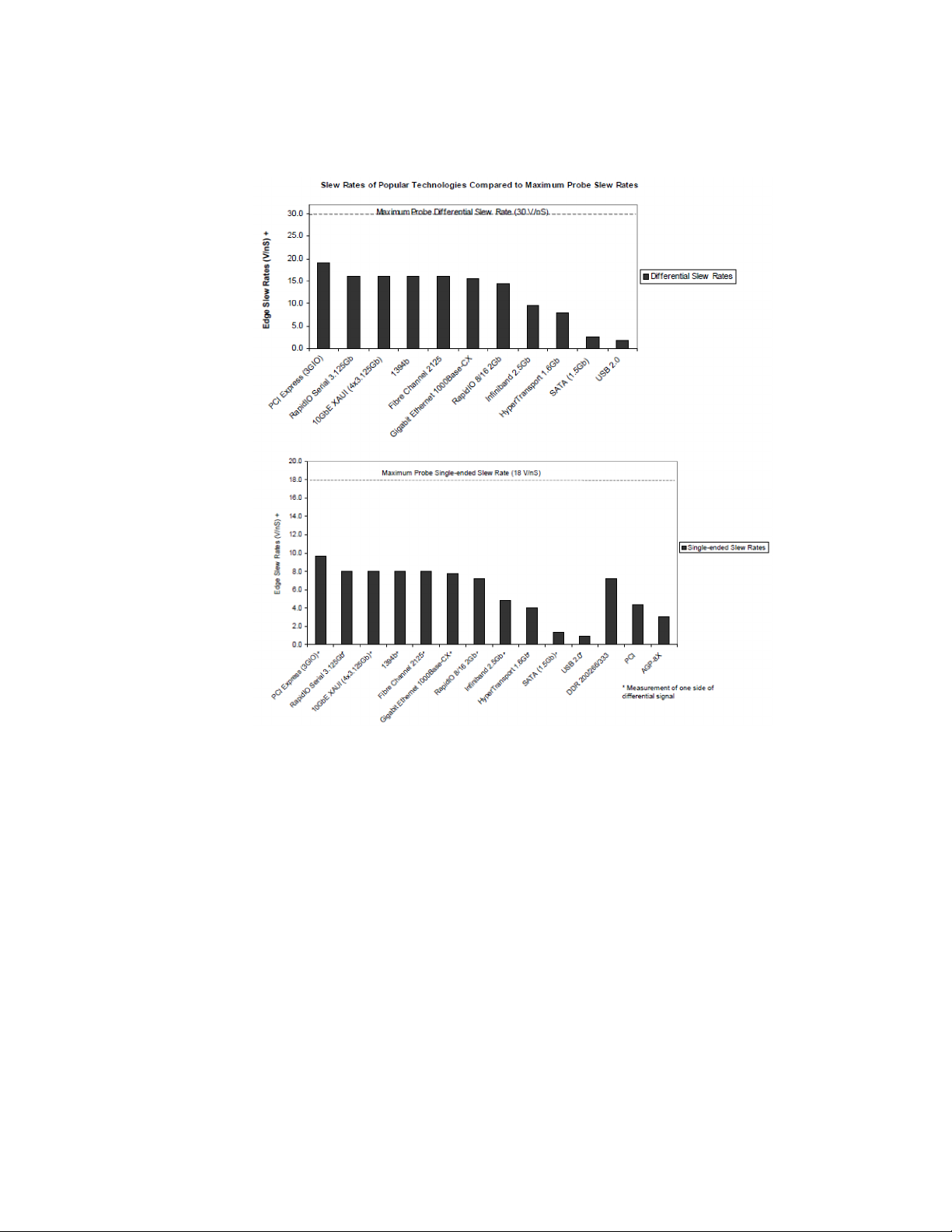
The following table shows the slew rates for several different technologies. The
maximum allowed input slew rate is 18 V/ns for single-ended signals and 30 V/ns
for differential signals. Table 6 shows that the maximum required slew rate for the
different technologies is much less that of the probe.
Table 6 Slew Rate Requirements
Name of Technology Differential
Signal
PCI Express (3GIO) YES 9.6 19.2 50 1.6
RapidIO Serial 3.125Gb YES 8.0 16.0 60 1.6
10GbE XAUI (4x3.125Gb) YES 8.0 16.0 60 1.6
1394b YES 8.0 16.0 60 1.6
Fibre Channel 2125 YES 8.0 16.0 75 1
Gigabit Ethernet 1000Base-CX YES 7.8 15.5 85 2.2
RapidIO 8/16 2Gb YES 7.2 14.4 50 1.2
Infiniband 2.5Gb YES 4.8 9.6 100 1.6
HyperTransport 1.6Gb YES 4.0 8.0 113 1.5
SATA (1.5Gb) YES 1.3 2.7 134 0.6
USB 2.0 YES 0.9 1.8 375 1.1
DDR 200/266/333 NO 7.2 n/a 300 3.6
PCI NO 4.3 n/a 500 3.6
Max
Single-Ended
Slew Rate
(V/ns)
*
Max
Differential
Slew Rate
(V/ns)
Driver Min Edge
Rate (20%-80%
†
ps)
Max Transmitter
Level (Diff V)
AGP-8X NO 3.1 n/a 137 0.7
* The probe specification is 18 V/ns
† The probe specification is 30 V/ns
InfiniiMax III+ Series Probes User’s Guide 31
Page 32
1 Using InfiniiMax III+ Series Probes
Figure 21 Slew Rates of Popular Technologies Compared to Maximum Probe Slew Rates
32 InfiniiMax III+ Series Probes User’s Guide
Page 33
Available Accessories
CAUTION
CAUTION
The following is a partial list of available probe and oscilloscope accessories.
Performance verification fixture
An E2655C or N5443A Performance Verification (PV) fixture is an
accessory that is used to properly position the probe during
performance verification testing as described in Chapter 7 and
Chapter 8.
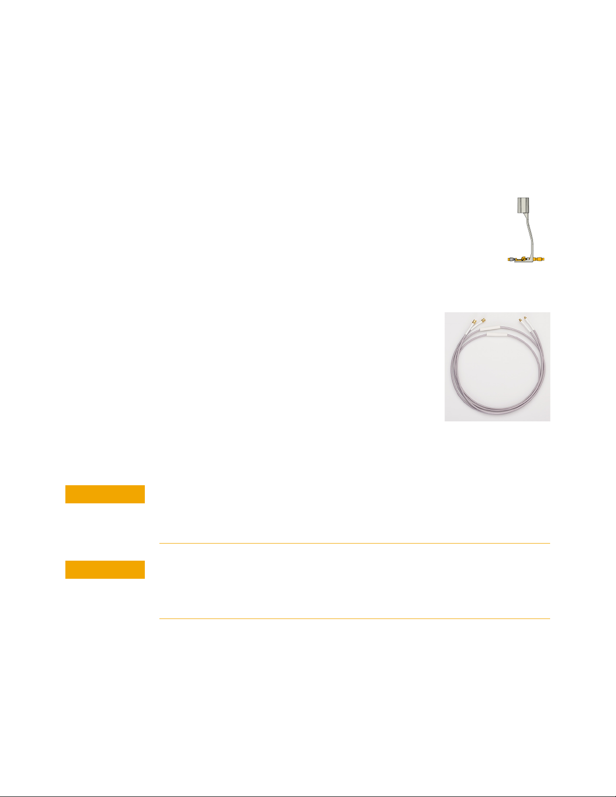
N5450B Extreme temperature cable extension kit
For extreme temperature testing, such as monitoring a
device in a temperature chamber, order the N5450B
InfiniiMax extreme temperature extension cable for use
with the MX0109A / N5441A solder-in heads.
Using InfiniiMax III+ Series Probes 1
Keysight’s Infiniimax probe amplifiers have a specified
operating temperature range from 5
MX0109A and N5441A probe heads can withstand
temperatures from –55°C to +150°C for up to 750 and 250
test cycles respectively. Use the extension cables to
physically separate the amplifier from the probe head which allows you to operate
the probe head inside a temperature chamber while the probe amplifier remains
outside the chamber.
o
C to 40o C, but the
None of the N2830/1/2A or N7000/1/2/3A probe amplifiers can withstand the
extreme temperatures (–55°C to +150°C) that the N5450B can withstand. When using
the N5450B extension cable, do not subject the InfiniiMax III+ probe amplifier to
extreme temperatures.
Besides the MX0109A and N5441A probe heads, none of the other probe heads are
designed for extreme temperature testing. For more information about the extreme
temperature probing solution for Keysight oscilloscopes, check out the Keysight data
sheet with the literature number, 5990-3504EN.
To ensure a high-quality measurement, the N5450B cable set have been
phase-matched at the factory. A coupling tag is included with the cables to ensure
the cables stay as a matched pair. To install the coupling tag, slip the small end of
each cable through the holes in the tag. The tag can be positioned anywhere along
the length of the cable and can withstand the temperature ranges specified.
InfiniiMax III+ Series Probes User’s Guide 33
Page 34

1 Using InfiniiMax III+ Series Probes
CAUTION
CAUTION
CAUTION
CAUTION
CAUTION
NOTE
NOTE
Avoid rapid changes in temperature that can lead to moisture accumulating in the
form of condensation on the probe components, as well as the DUT. If this occurs, wait
until the moisture has evaporated before making any measurements.
Additional care must be taken when handling probe heads used during extreme
temperature cycling because this process makes the probe heads less robust.
Secure the ends of the extension cable near the probe head in the temperature
chamber such that the probe head legs are not tugged or moved around significantly.
Prevent abrasion and tears in the cable’s jacket, do not rest the extension cables on
any metal objects or objects with sharp edges.
Do not kink the cables. The cables are designed to be flexible, but are not designed to
be bent sharply.
Keep your extreme temperature testing probes separate from the probes that you use under
milder conditions. This is because cycling probe heads through extreme temperature ranges
has a marked affect on their lifetimes. Only the lifetime of the probe head is affected by
temperature cycling. The extension cables and probe amplifier should not need to be replaced
with extended temperature cycling.
Discoloration or texture changes are possible with the extension cables. These changes do
not, however, affect the performance or the quality of a measurement.
N5449A high impedance adapter
The N5449A high impedance adapter includes one N2873A 10:1 passive probe.
The adapter is specifically tuned for the N2873A probe. Similar probes (1
input) can be used. Other probes may not meet the bandwidth specification.
86100D sampling scope adapters
Two adapters are available for connecting probes to the Infiniium 86100D DCA-X
sampling oscilloscope or other RF instruments. The N1022B sampling scope
adapter allows you to connect N2830/1/2A probes. The N5477A sampling scope
adapter allows you to connect N7000/1/2A probes.
ΜW
34 InfiniiMax III+ Series Probes User’s Guide
Page 35

Using InfiniiMax III+ Series Probes 1
CAUTION
N2852A AutoProbe II to AutoProbe III Interface Adapter
This adapter allows you to connect a probe with AutoProbe II interface such as the
N7000A / N7001A / N7002A / N7003A InfiniiMax III+ probe to a Keysight
UXR-Series (40GHz or higher) Infiniium oscilloscope that has the AutoProbe III
interface.
The adapter also allows you to connect a probe with AutoProbe I interface such as
the N2830A-series InfiniiMax III+ probe to a Keysight UXR-Series (40GHz or
higher) Infiniium oscilloscope. To do this, you need to connect the N5442A (50
/ N5449A (1M
To know more about the N2852A adapter, visit
http://www.keysight.com/find/N2852A and then download the adapter’s user
guide available in the Document Library tab.
Ω) AutoProbe I to II adapter to the N2852A adapter.
Care should be taken while handling the N2852A adapter's RF cable.
Avoid bending this cable backwards or kinking the cable in order to
ensure measurements accuracy.
Ω)
InfiniiMax III+ Series Probes User’s Guide 35
Page 36
1 Using InfiniiMax III+ Series Probes
WARNING
WARNING
WARNING
WARNING
WARNING
WARNING
Safety Information
This manual provides information and warnings essential for operating this probe
in a safe manner and for maintaining it in safe operating condition. Before using
this equipment and to ensure safe operation and to obtain maximum performance
from the probe, carefully read and observe the following warnings, cautions, and
notes.
This product has been designed and tested in accordance with accepted industry
standards, and has been supplied in a safe condition. The documentation contains
information and warnings that must be followed by the user to ensure safe
operation and to maintain the product in a safe condition.
Note the external markings on the probe that are described in this document.
To avoid personal injury and to prevent fire or damage to this product or products
connected to it, review and comply with the following safety precautions. Be aware
that if you use this probe assembly in a manner not specified, the protection this
product provides may be impaired.
Use Only Grounded Instruments.
Do not connect the probe’s ground lead to a potential other than earth ground.
Always make sure the probe and the oscilloscope are grounded properly.
Connect and Disconnect Properly.
Connect the probe to the oscilloscope and connect the ground lead to earth ground
before connecting the probe to the circuit under test. Disconnect the probe input and
the probe ground lead from the circuit under test before disconnecting the probe
from the oscilloscope.
Observe Probe Ratings.
Do not apply any electrical potential to the probe input which exceeds the maximum
rating of the probe. Make sure to comply with the voltage versus frequency derating
curve found in this manual.
Indoor Use Only.
Do not operate in wet/damp environments. Keep product surfaces dry and clean.
Do Not Operate With Suspected Failures. Refer to qualified service personnel.
Never leave the probe connected to a conductor while it is not connected to an
oscilloscope or voltage measuring instrument.
36 InfiniiMax III+ Series Probes User’s Guide
Page 37

Using InfiniiMax III+ Series Probes 1
WARNING
WARNING
WARNING
WARNING
WARNING
CAUTION
WARNING
WARNING
WARNING
Do not use a probe which is cracked, damaged or has defective leads.
Do not install substitute parts or perform any unauthorized modification to the
probe.
Do not operate the probe or oscilloscope in the presence of flammable gasses or
fumes. Operation of any electrical instrument in such an environment constitutes a
definite safety hazard.
Do not use the probe or oscilloscope in a manner not specified by the manufacturer.
Service instructions are for trained service personnel. To avoid dangerous electric
shock, do not perform any service unless qualified to do so. Do not attempt internal
service or adjustment unless another person, capable of rendering first aid and
resuscitation, is present.
The probe cable is a sensitive part of the probe and, therefore, you should be careful
not to damage it through excessive bending or pulling. Avoid any mechanical shocks
to this product in order to guarantee accurate performance and protection.
Concerning the Oscilloscope or Voltage Measuring Instrument to Which
the Probe is Connected
Whenever it is likely that the ground protection is impaired, you must make the
instrument inoperative and secure it against any unintended operation.
If you energize the instrument by an auto transformer (for voltage reduction or
mains isolation), the ground pin of the input connector terminal must be connected
to the earth terminal of the power source.
Before turning on the instrument, you must connect the protective earth terminal of
the instrument to the protective conductor of the (mains) power cord. The mains
plug shall only be inserted in a socket outlet provided with a protective earth
contact. You must not negate the protective action by using an extension cord
(power cable) without a protective conductor (grounding). Grounding one conductor
of a two-conductor outlet is not sufficient protection.
InfiniiMax III+ Series Probes User’s Guide 37
Page 38

1 Using InfiniiMax III+ Series Probes
WARNING
WARNING
Only fuses with the required rated current, voltage, and specified type (normal blow,
time delay, etc.) should be used. Do not use repaired fuses or short-circuited fuse
holders. To do so could cause a shock or fire hazard.
Capacitors inside the instrument may retain a charge even if the instrument is
disconnected from its source of supply.
38 InfiniiMax III+ Series Probes User’s Guide
Page 39

Service
Probe calibration fails
Using InfiniiMax III+ Series Probes 1
The following symptoms may indicate a problem with the probe or the way it is
used. The probe is a high frequency device with many critical relationships
between parts. For example, the frequency response of the amplifier on the hybrid
is trimmed to match the output coaxial cable. As a result, to return the probe to
optimum performance requires factory repair. If the probe is under warranty,
normal warranty services apply.
Probe calibration failure with an oscilloscope is usually caused by improper setup.
If the calibration will not pass, check the following:
• Check that the probe passes a waveform with the correct amplitude.
• If the probe is powered by the oscilloscope, check that the offset is
approximately correct. The probe calibration cannot correct major failures.
• Be sure the oscilloscope passes calibration without the probe.
Incorrect pulse response (flatness)
If the probe's pulse response shows a top that is not flat, check for the following:
• Output of probe must be terminated into a proper 50W termination. If you are
using the probe with an Infiniium oscilloscope, this should not be a problem. If
you are using the probe with other test gear, insure the probe is terminated into
a low reflectivity 50W load (~ ±2%).
• If the coax or coaxes of the probe head in use has excessive damage, then
reflections may be seen within ~ 1 ns of the input edge. If you suspect a probe
head, swap it with another probe head and see if the non-flatness problem is
fixed.
• If the one of the components in the tip have been damaged there may be a
frequency gain non-flatness at around 40 MHz. If you suspect a probe head,
swap it with another probe head and see if the non-flatness problem is fixed.
Incorrect input resistance
The input resistance is determined by the probe head in use. If the probe head is
defective, damaged, or has been exposed to excessive voltage, the input resistor
may be damaged. If this is the case, the probe head is no longer useful. A new
probe head will need to be obtained either through purchase or warranty return.
InfiniiMax III+ Series Probes User’s Guide 39
Page 40

1 Using InfiniiMax III+ Series Probes
NOTE
NOTE
Incorrect offset
Assuming the probe head in use is properly functioning, incorrect offset may be
caused by defect or damage to the probe amplifier or by lack of probe calibration
with the oscilloscope.
Returning the probe for service
If the probe is found to be defective we recommend sending it to an authorized
service center for all repair and calibration needs. Perform the following steps
before shipping the probe back to Keysight Technologies for service.
1 Contact your nearest Keysight sales office for information on obtaining an RMA
number and return address.
2 Write the following information on a tag and attach it to the malfunctioning
equipment.
• Name and address of owner
• Product model number (for example, N2830A)
• Product Serial Number (for example, MYXXXXXXXX)
• Description of failure or service required
Include probing and browsing heads if you feel the probe is not meeting performance
specifications or a yearly calibration is requested.
3 Protect the probe by wrapping in plastic or heavy paper.
4 Pack the probe in the original carrying case or if not available use bubble wrap
or packing peanuts.
5 Place securely in sealed shipping container and mark container as "FRAGILE".
If any correspondence is required, refer to the product by serial number and model number.
Contacting Keysight Technologies
For technical assistance, contact your local Keysight Call Center.
• In the Americas, call 1 (800) 829-4444
• In other regions, visit http://www.keysight.com/find/assist
Before returning an instrument for service, you must first call the Call Center at 1
(800) 829-4444.
40 InfiniiMax III+ Series Probes User’s Guide
Page 41

Keysight InfiniiMax III+ Series Probes
NOTE
User’s Guide
2 Using InfiniiMax III+ Probe
Heads
Recommended Configurations at a Glance 42
N5444A InfiniiMax III 2.92 mm/3.5 mm/SMA Probe Head 44
N5439A InfiniiMax III ZIF Probe Head 47
N5445A InfiniiMax III Differential Browser Probe Head 53
N5441A InfiniiMax III Solder-In Head (discontinued) 65
MX0109A and N2836A InfiniiMode Solder-In Heads 59
N2848A QuickTip InfiniiMode Probe Head 68
N2835A InfiniiMax III+ Differential Connectivity Kit and Accessories 72
Strain Relieving the Probe Heads 74
Soldering Tips 76
This chapter describes various probe heads. The probe configurations are listed in
the order of the best performance to the least performance in terms of bandwidth
and input loading characteristics. The recommended configurations are designed
to give the best probe performance for different probing situations. This allows you
to quickly make the measurements you need with confidence in the performance
and signal fidelity. Using the recommended connection configurations is your key
to making accurate oscilloscope measurements with known performance levels.
Graphs showing the performance of the heads for each probe amplifier are shown in
Chapter 6,
41
Page 42
2 Using InfiniiMax III+ Probe Heads
Recommended Configurations at a Glance
Table 7 Configurations at a Glance (Sheet 1 of 2)
Recommended
Order of Use
N5444A InfiniiMax III 2.92 mm Head (Refer to page 44.)
N5439A InfiniiMax III ZIF Head (Refer to page 47.)
N5445A InfiniiMax III Browser (Refer to page 53.)
BW
(GHz)
N2830A: 4
N2831A: 8
N2832A: 13
N7000A: 8
N7001A: 13
N7002A: 16
N7003A: 20
N2830A: 4
N2831A: 8
N2832A: 13
N7000A: 8
N7001A: 13
N7002A: 16
N7003A: 20
N2830A: 4
N2831A: 8
N2832A: 13
N7000A: 8
N7001A: 13
N7002A: 16
N7003A: 20
Cdiff *
(pF)
— — Differential and Single-ended signals
32 fF 44 fF Single-ended signals only
35 fF 50 fF Differential and Single-ended signals
Cse
(pF)
†
Usage
InfiniiMode compatible
For cabled measurements. Can terminate to a non-ground
voltage.
Solder-in hands free connection when physical size is critical
Extremely low loading measurement with N5440A/47A ZIF tips
Hard to reach targets
Very small fine pitch targets
General purpose troubleshooting of signals
Handheld browsing
Variable pitch spacing from 20 mil to 125 mil
MX0109A InfiniiMax III Extreme Temperature Solder-In Head (Refer to page 59.)
N2830A: 4
N2831A: 8
N2832A: 13
N7000A: 8
N7001A: 13
N7002A: 16
N7003A: 20
42 InfiniiMax III+ Series Probes User’s Guide
108 fF 140 fF Differential and Single-ended signals
InfiniiMode Compatible
Solder-in hands free connection
Also suitable for Extreme Temperature testing
Page 43
Table 7 Configurations at a Glance (Sheet 2 of 2)
Using InfiniiMax III+ Probe Heads 2
Recommended
Order of Use
BW
(GHz)
Cdiff *
(pF)
Cse
(pF)
†
N2836A InfiniiMode Solder-In Head (Refer to page 59.)
N2830A: 4
108 fF 140 fF Differential and Single-ended signals
N2831A: 8
N2832A: 13
N7000A: 8
N7001A: 13
N7002A: 16
N7003A: 20
N2848A QuickTip Head (Refer to page 68.)
N2830A: 4
340 fF 200 fF Differential and Single-ended signals
N2831A: 8
N2832A: >12
N7000A: 8
N7001A: 13
N7002A: 16
N7003A: >16
* Capacitance seen by differential signals
† Capacitance seen by single-ended signals
Usage
InfiniiMode Compatible
Solder-in hands free connection
InfiniiMode Compatible
Easy head-to-tip connection in tight space
Solder-in hands free connection
InfiniiMax III+ Series Probes User’s Guide 43
Page 44
2 Using InfiniiMax III+ Probe Heads
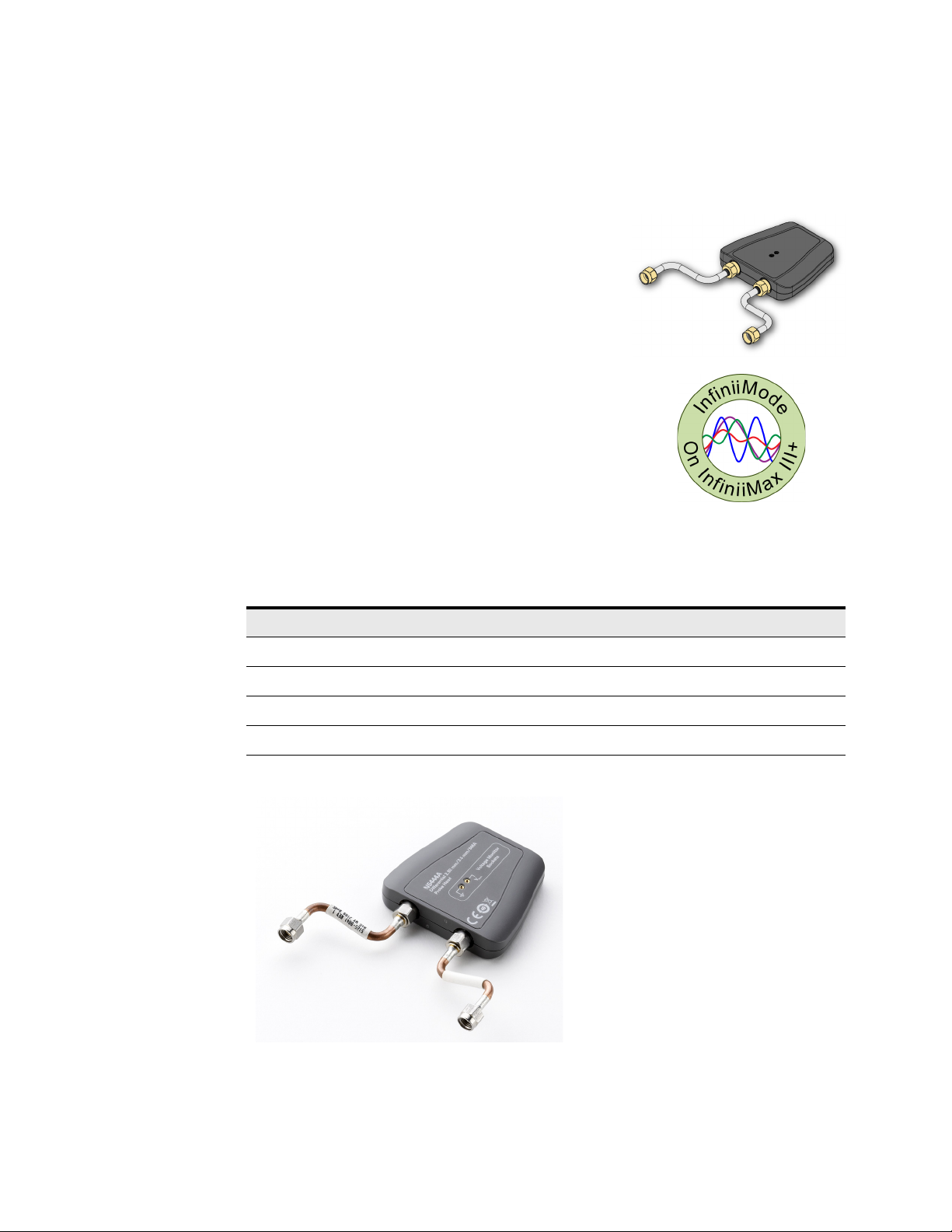
N5444A InfiniiMax III 2.92 mm/3.5 mm/SMA Probe Head
The N5444A InfiniiMax III 2.92mm/3.5mm/SMA
probe head provides 30 GHz bandwidth and allows
you to connect two 2.92mm, 3.5mm, or SMA
cables to make a differential measurement on a
single oscilloscope channel.
The N5444A provides for a termination to a
common DC voltage rather than to ground, which
is required for many signal standards. It is
implemented such that from DC to approximately
1 kHz, the termination is 55 Ohms to the
termination voltage, and above approximately
10 kHz, the termination is 50 Ohms to 0.9 times the
termination voltage. The termination voltage range
is ±4V with a minimum step of 5 mV and a
maximum current of 80 mA. The termination
voltage can be controlled internally by the
oscilloscope or applied externally using the supplied DC jack.
Table 8 Bandwidth
Probe Amplifier BW Probe Amplifier BW
N2830A 4 GHz N7000A 8 GHz
N2831A 8 GHz N7001A 13 GHz
N2832A 13 GHz N7002A 16 GHz
N7003A 20 GHz
Figure 22 N5444A InfiniiMax III 2.92mm/3.5mm/SMA Probe Head
44 InfiniiMax III+ Series Probes User’s Guide
Page 45
NOTE
For performance plots, refer to Chapter 6, “Performance Plots.
CAUTION
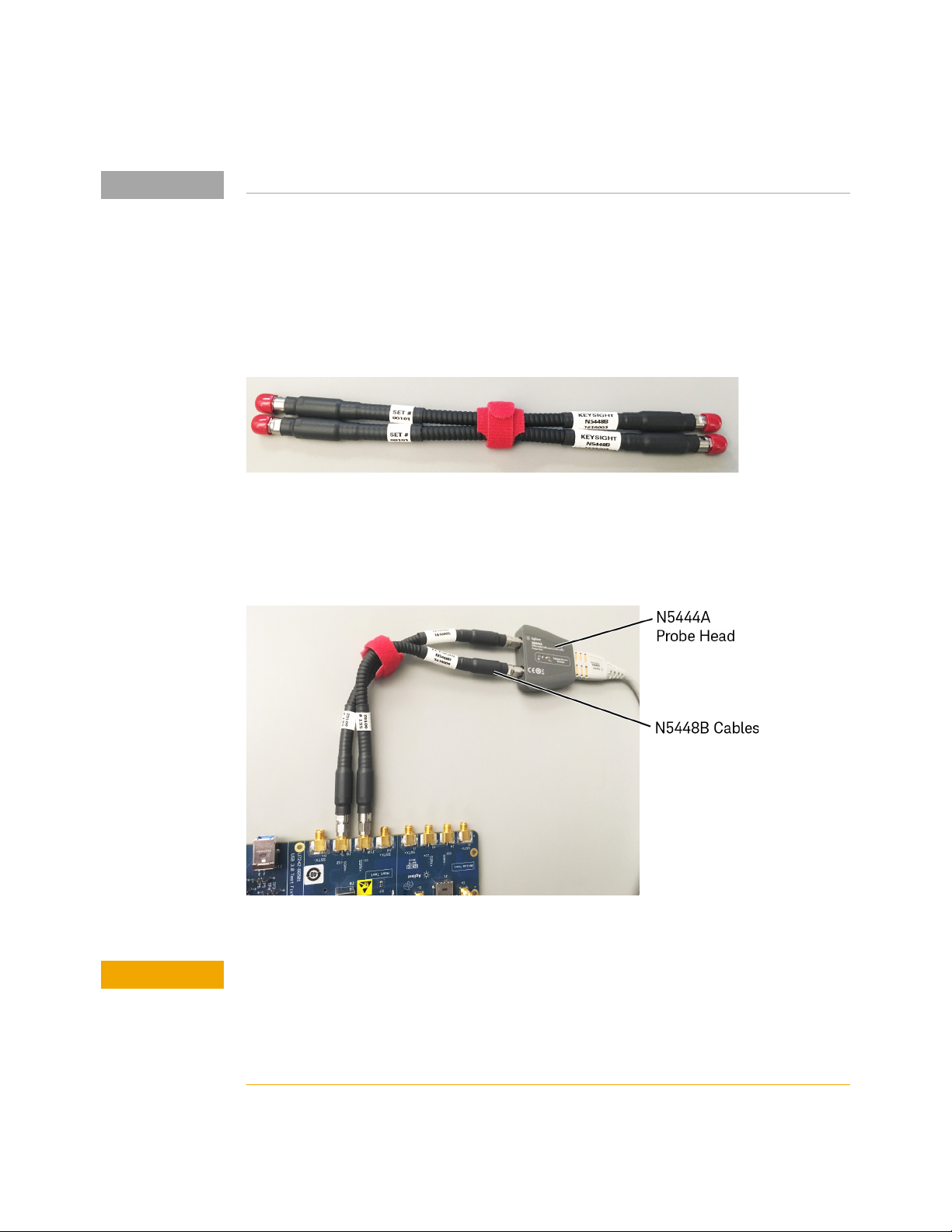
N5448B Coaxial Phase Matched Cable Pair
For extending the cable length of the N5444A InfiniiMax III probe head and add flexibility
and convenience to the probing setup, you can order N5448B 10 inches (25 cm) long
coaxial phase matched cable pair. This cable pair supports 2.92 mm male-to-2.92 mm
male connection.
Figure 23 N5448B Coaxial Phased Matched Cable Pair
Using InfiniiMax III+ Probe Heads 2
Before connecting these cables to the N5444A probe head, you must first remove the
supplied rigid cables of the N5444A probe head. Figure 24 on page 45 shows the N5448B
cables attached to the N5444A probe head.
Figure 24 N5444A Probe Head With N5448B Cables Attached
The maximum bend radius for the N5448B coaxial cable pair is 30 mm. Bending these
cables at too tight a radius or twisting the cables can cause damage, reduce
performance, and impact the precision of these cables.
Also, ensure that the plastic caps that are provided with these cables are installed
when the cables are not in use.
InfiniiMax III+ Series Probes User’s Guide 45
Page 46

2 Using InfiniiMax III+ Probe Heads
For details on the N5448B cable, refer to its guide available in the Document
Library tab of this product’s page on www.keysight.com.
Probe Offset Calibration with the N5444A
To achieve more accurate probe offset calibration with the N5444A, an
SMA shorting adapter
adapter is provided with the N5444A (with unit serial number
US50072545 or higher) and should be connected to the N5444A's "—"
input connector during the calibration. The latest Infiniium firmware includes
instructions on the Probe Calibration dialog box to remind you to install the
adapter. If the Infiniium oscilloscope's firmware is older than version 5.50.33, you
can still attach the adapter and the resulting calibration will be valid.
(Keysight part number: 1250-3999) is required. This
46 InfiniiMax III+ Series Probes User’s Guide
Page 47
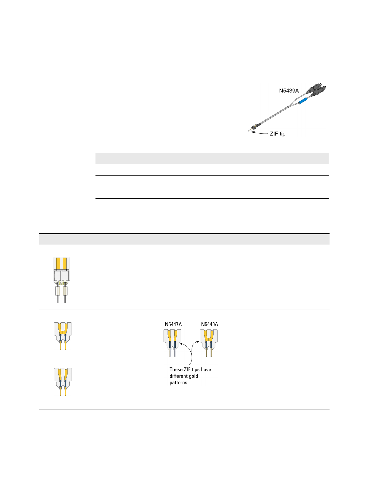
N5439A InfiniiMax III ZIF Probe Head
The N5439A Zero Insertion Force (ZIF) probe head
supports the three types of economical replaceable
tips that are shown in Table 10. Solder as many
tips onto your DUT as needed. Because of the ZIF
tip’s extremely low loading, the tips can remain on
the DUT as you easily move the probe head from
one probing site to the next.
Table 9 Bandwidth
Probe Amplifier BW Probe Amplifier BW
N2830A 4 GHz N7000A 8 GHz
N2831A 8 GHz N7001A 13 GHz
N2832A 13 GHz N7002A 16 GHz
Using InfiniiMax III+ Probe Heads 2
N7003A 20 GHz
Table 10 Available ZIF Tips
ZIF Tip Description Variable Tip Spacing Qty
N2838A 25 GHz 450W PC board tip provides robust design with
high bandwidth.
N5440A 28 GHz 450W ceramic
(normal sensitivity) for
extremely low probe
loading.
N5447A The N5447A ZIF tip is not
compatible with the
N2830/1/2A or
N7000/1/2/3A probes.
Compatible only with
InfiniiMax III N2800/1/2/3A
probes.
5 mil to 250 mil
(0.127 mm to 6.35 mm)
5 mil to 80 mil
(0.127 mm to 2 mm)
5 mil to 80 mil
(0.127 mm to 2 mm)
5
5
5
InfiniiMax III+ Series Probes User’s Guide 47
Page 48
2 Using InfiniiMax III+ Probe Heads
NOTE
NOTE
NOTE
NOTE
CAUTION
The N5439A does not include any ZIF tips. You must order either the N2838A or N5440A in
addition to N5439A.
The N5447A ZIF tip is not compatible with N2830/1/2A or N7000/1/2/3A probes.
For performance plots, refer to Chapter 6, “Performance Plots.
Ensuring maximum N2838A tip performance
The specifications and performance plots of the N2838A ZIF tip were measured
with a nominal spacing of 40 mil (1 mm). In order to achieve the proper response
as shown in the performance plots, keep the mini-axial lead resistors roughly
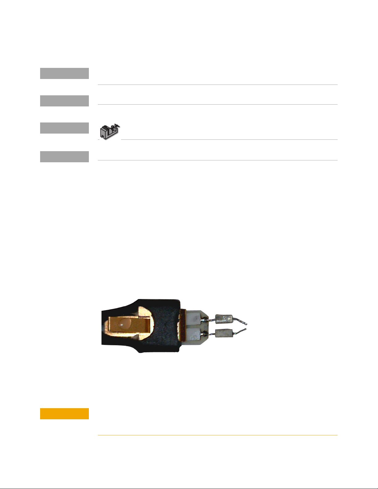
parallel as shown in Figure 43, and use the tip wires on the mini-axial leads to get
the desired span.
To install or repair N2838A resistor leads, refer to “Replacing Axial Resistor
Tips" on page 78.
If you need to position the resistors different than shown in this figure (that is,
resistor bodies close together or spread apart), use N2807A and N2808A
PrecisionProbe products to perform an AC calibration of the probe, which properly
captures the response. Increasing the spacing to 250 mil degrades the
performance some, but PrecisionProbe can be used to compensate or qualify the
effect.
Figure 25 Proper Position of Resistors
Soldering a ZIF tip to the DUT
Before using the following procedure, refer to “Soldering Tips" on page 76.
The ceramic ZIF tips are very fragile. They must be manufactured in this way in order to
meet the high-performance, high bandwidth applications they are intended for. Be
extremely careful when handling.
48 InfiniiMax III+ Series Probes User’s Guide
Page 49
Using InfiniiMax III+ Probe Heads 2
NOTE
CAUTION
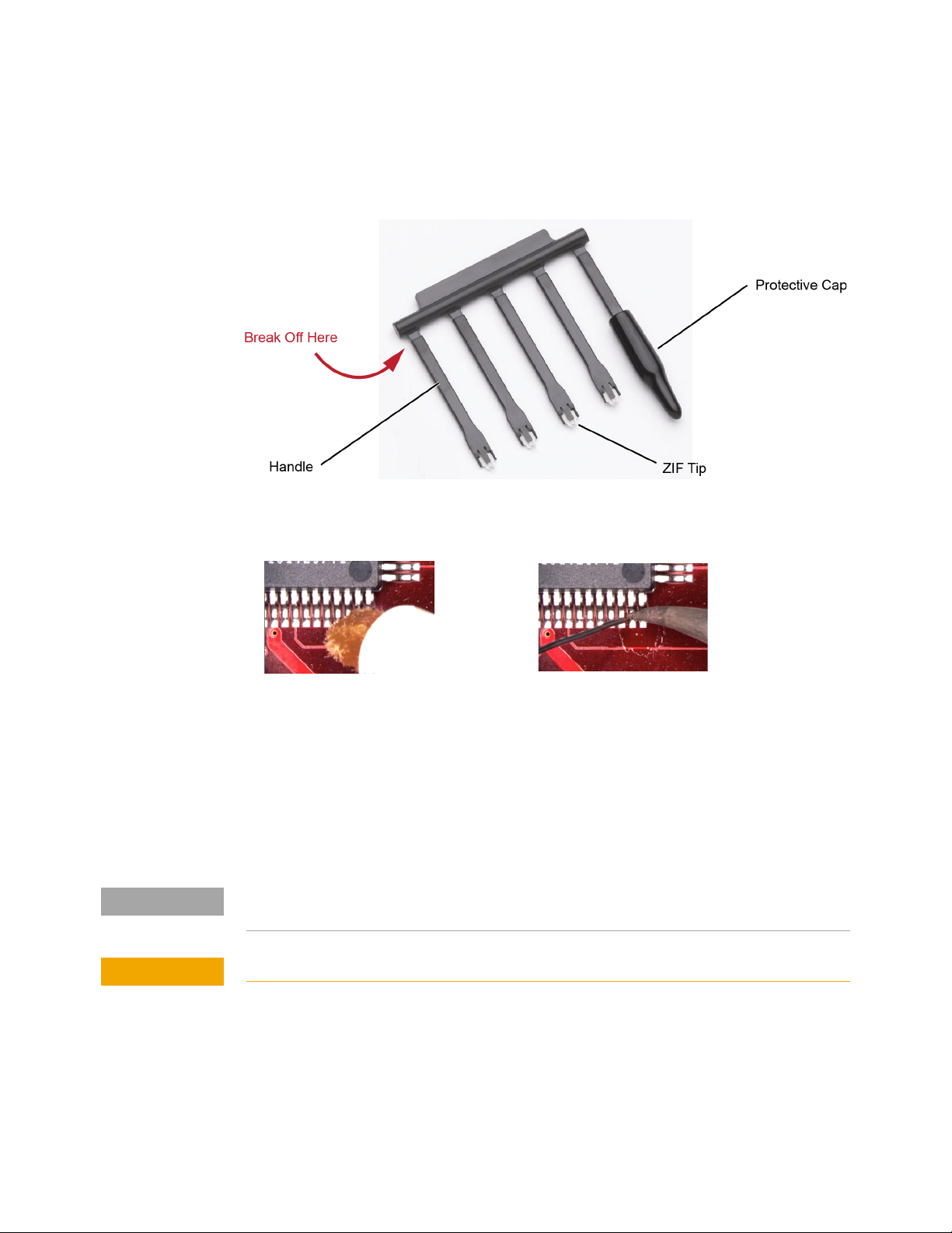
Break off a ZIF tip/handle combination from the packaging holder at the point
1
shown in the figure.
Figure 26 Five ZIF Tips on Packaging
2 Flux and tin the leads on the target DUT.
Figure 27 Preparing the DUT Leads
3 While holding the plastic form, form the ZIF tip wires to match the DUT’s pitch
and angle.
4 Flux the ZIF tip wires and DUT leads.
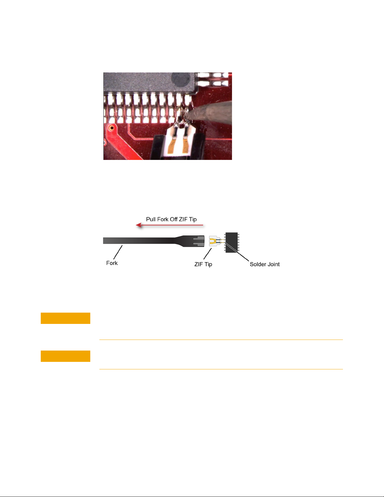
5 Position the ZIF tip with the gold traces facing up as shown in Figure 28 on
page 50 and carefully re-flow the solder. This orients the tip so that it will
properly mate with the probe head.
When soldering the tip to your DUT, use the tip handle to hold the tip. This allows you to
position these small tips without damaging them.
Do not dwell on this solder joint.
InfiniiMax III+ Series Probes User’s Guide 49
Page 50
2 Using InfiniiMax III+ Probe Heads
CAUTION
CAUTION
Figure 28 Soldering the ZIF Tip
6 Pull the ZIF handle from the ZIF tip in the direction shown in Figure 29. ZIF tips
can be carefully handled with your fingertips and reinserted into a plastic
handle if necessary.
Figure 29 Removing the Handle from the ZIF Tip
7 You can connect ZIF tips to any of the locations on a DUT that you need to
probe. The probe head can be quickly moved between the tips.
Always mechanically strain-relieve the ZIF head before using to protect both your
probe accessories and DUT from damage. Refer to “Strain Relieving the Probe
Heads" on page 74.
Be careful not to damage the tip wires when handling the ZIF tips. Wires can be
carefully reshaped with tweezers or fingers if necessary.
Connecting the probe head to the ZIF tip
1 Add strain relieve for the ZIF probe head as described in “Strain Relieving the
Probe Heads" on page 74.
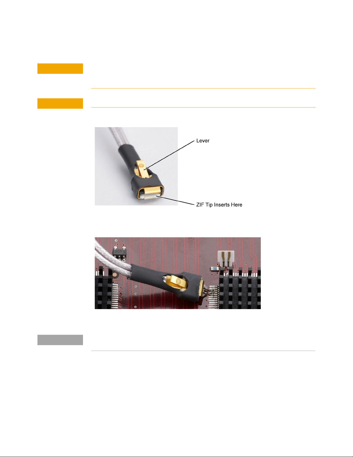
2 Form the coaxial cables to bring the probe head near the tip. Press the lever
down on the ZIF probe head (see Figure 30) and slide the probe head onto the
tip. Pressing on this lever removes the clamping force of the connector and
enables you to insert or remove ZIF tips.
50 InfiniiMax III+ Series Probes User’s Guide
Page 51
Using InfiniiMax III+ Probe Heads 2
CAUTION
CAUTION
NOTE
Stop if you encounter any resistance at all when sliding the probe head over the ZIF
tip. Check your alignment, make sure the lever is pressed, and try again. Inserting the
ZIF tip should require “zero” insertion force.
Always use the lever when inserting or removing ZIF tips.
Figure 30 Probe Head with Location of the Lever
Figure 31 Probe Head Connected to a Soldered ZIF Tip
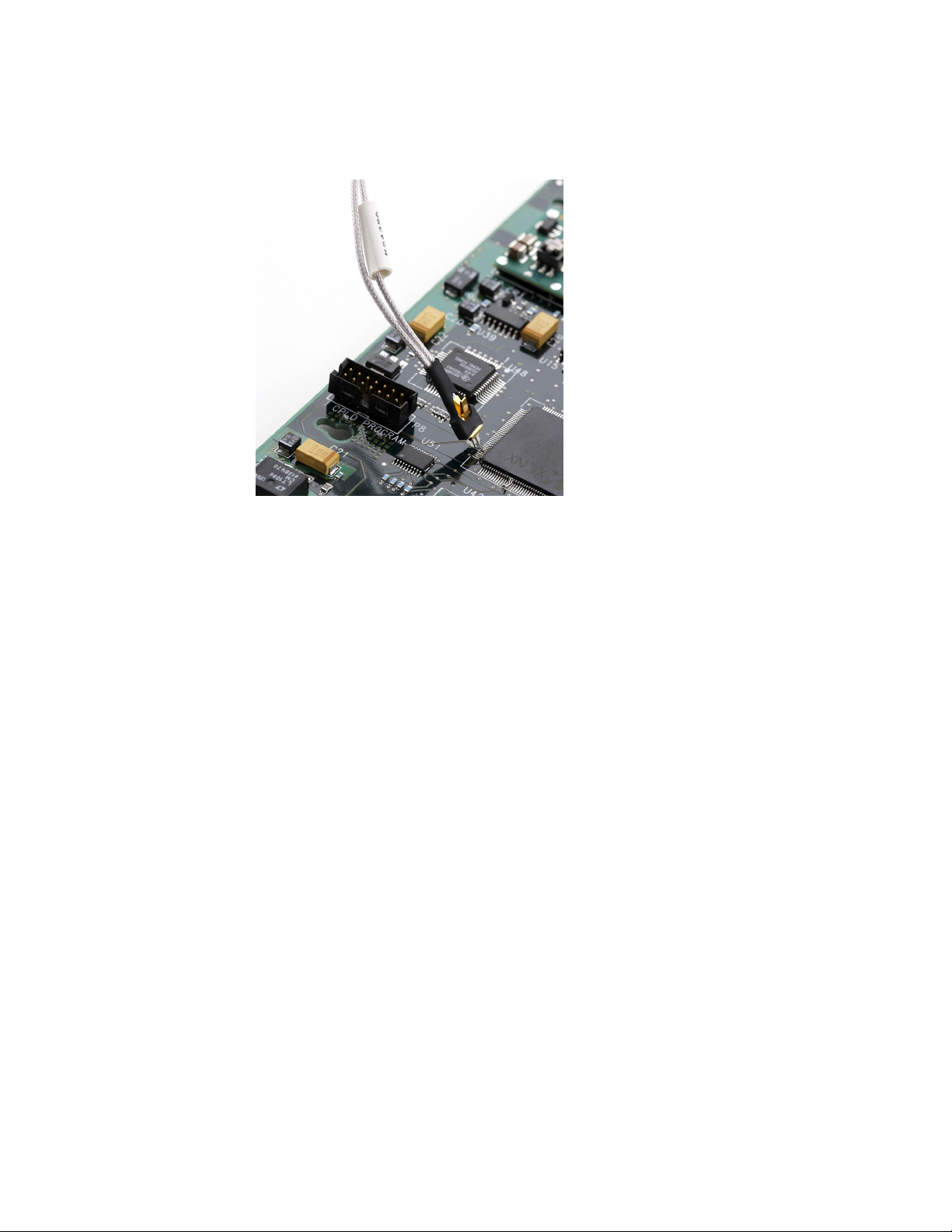
For more repeatable results, orient the probe connection perpendicular to the device as
shown in Figure 32 on page 52.
3 To move the probe head to a different tip, press the lever and remove the probe
head from the ZIF tip. The ZIF tip remains soldered to the DUT. Then, simply
connect the ZIF head to another ZIF tip at a different location on the DUT.
InfiniiMax III+ Series Probes User’s Guide 51
Page 52
2 Using InfiniiMax III+ Probe Heads
Figure 32 Probe Oriented Perpendicular to Device
52 InfiniiMax III+ Series Probes User’s Guide
Page 53
Using InfiniiMax III+ Probe Heads 2
NOTE
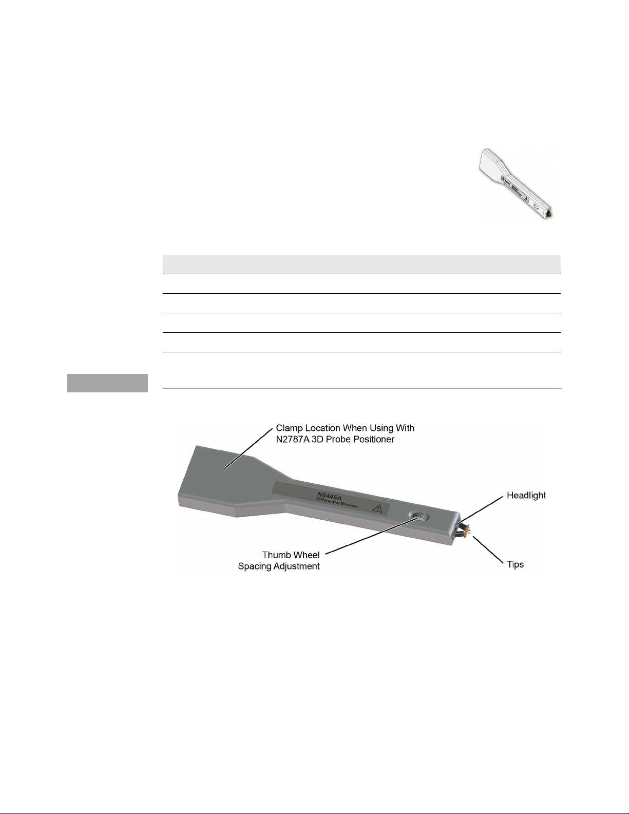
N5445A InfiniiMax III Differential Browser Probe Head
The N5445A browser head (30 GHz) is the best choice for the
general-purpose trouble shooting of differential signals with
spring-loaded tips and variable spacing from 20 mil to 125 mil
(or 0.5 mm to 3.1 mm).
The span between the signal tips is easily adjusted with a
thumb wheel on the browser (see Figure 33).
Table 11 Bandwidth
Probe Amplifier BW Probe Amplifier BW
N2830A 4 GHz N7000A 8 GHz
N2831A 8 GHz N7001A 13 GHz
N2832A 13 GHz N7002A 16 GHz
N7003A 20 GHz
For performance plots, refer to Chapter 6, “Performance Plots.
Figure 33 N5445A InfiniiMax III Differential Browser Head
Using the LED headlights
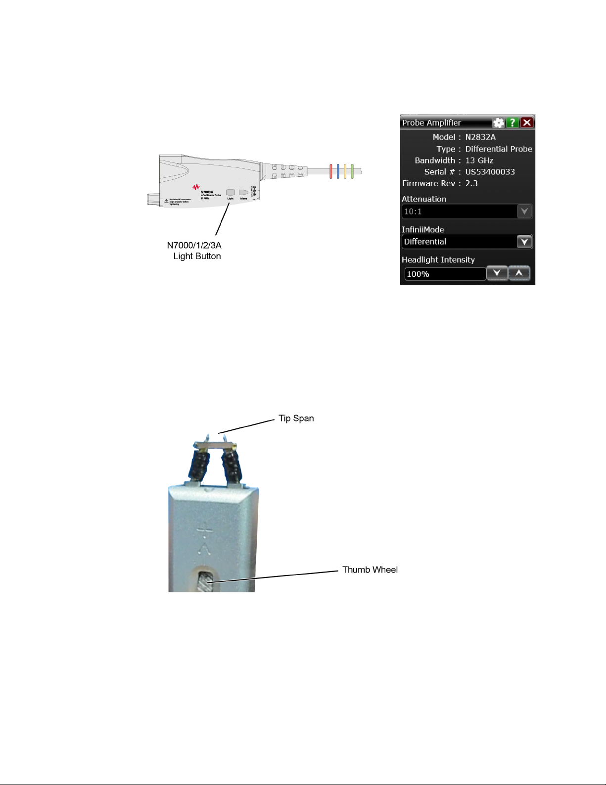
The browser’s tip includes an LED headlight that illuminates the probing area for
better visibility. The headlight intensity can be controlled from the oscilloscope’s
Probe Amplifier dialog box when using an N2830/1/2A or N7000/1/2/3A probes.
On N7000/1/2/3A probes, you can also use the Light button. Pressing and holding
this button will ramp the intensity of the headlight.
InfiniiMax III+ Series Probes User’s Guide 53
Page 54
2 Using InfiniiMax III+ Probe Heads
Figure 34 Headlight Intensity from N7000/1/2/3A Light Button or Dialog Box
Adjusting the tip span
Turn the browser’s thumb wheel (see Figure 35) to adjust the tip spacing from 20
to 125 mil (0.5 mm to 3.1 mm). Do not force the adjustment near the end of its
range.
Figure 35 Adjusting the Tip Span
54 InfiniiMax III+ Series Probes User’s Guide
Page 55
Tip-span entry for probe calibration
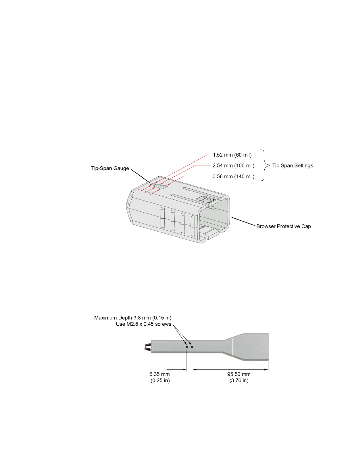
When calibrating the probe, you will be prompted to enter the span setting on the
oscilloscope’s Probe Calibration dialog box. To determine the tip span, do the
following steps:
1 Adjust the browser’s tip span for your measurement.
2 Locate the tip-span gauge on the browser’s protective cap as shown in
Figure 36.
3 Determine which of the three possible tip-span settings most closely matches
the browser’s tip span.
Using InfiniiMax III+ Probe Heads 2
Figure 36 Tip Span Gauge on Browser Protective Cap
Mounting the Browser
There are two holes on the back side of the browser. Use these holes to mount the
browser to a customer designed holder. Figure 37 below shows the dimensions of
these mounting holes.
Figure 37 Dimensions of Mounting Holes
InfiniiMax III+ Series Probes User’s Guide 55
Page 56
2 Using InfiniiMax III+ Probe Heads
CAUTION
CAUTION
CAUTION
CAUTION
Probe along the browser’s axis
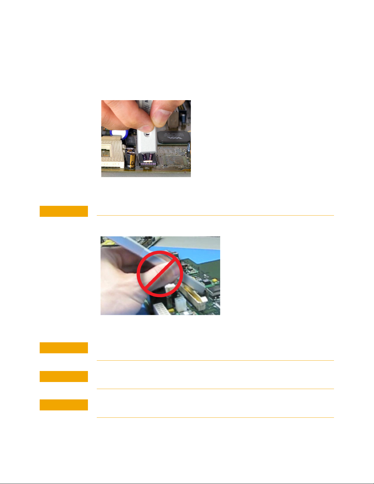
To prevent tip damage, probe along the browser’s axis as shown in Figure 38. Hold
the probe vertical and perpendicular to the circuit board.
Figure 38 Proper Probe Handling
To avoid damaging the browser’s tips, do not apply a side load to the browser.
Figure 39 Improper Probe Handling
Do not apply too much force when browsing. The weight of the probe in your hand
should be sufficient. The axial travel of the probe is about 15 mils (0.4 mm).
The browser’s protective cap should be kept on the browser at all times except when
probing.
Always remove the browser from the device under test (DUT) before disconnecting the
probe amp from the oscilloscope.
56 InfiniiMax III+ Series Probes User’s Guide
Page 57
Replaceable parts
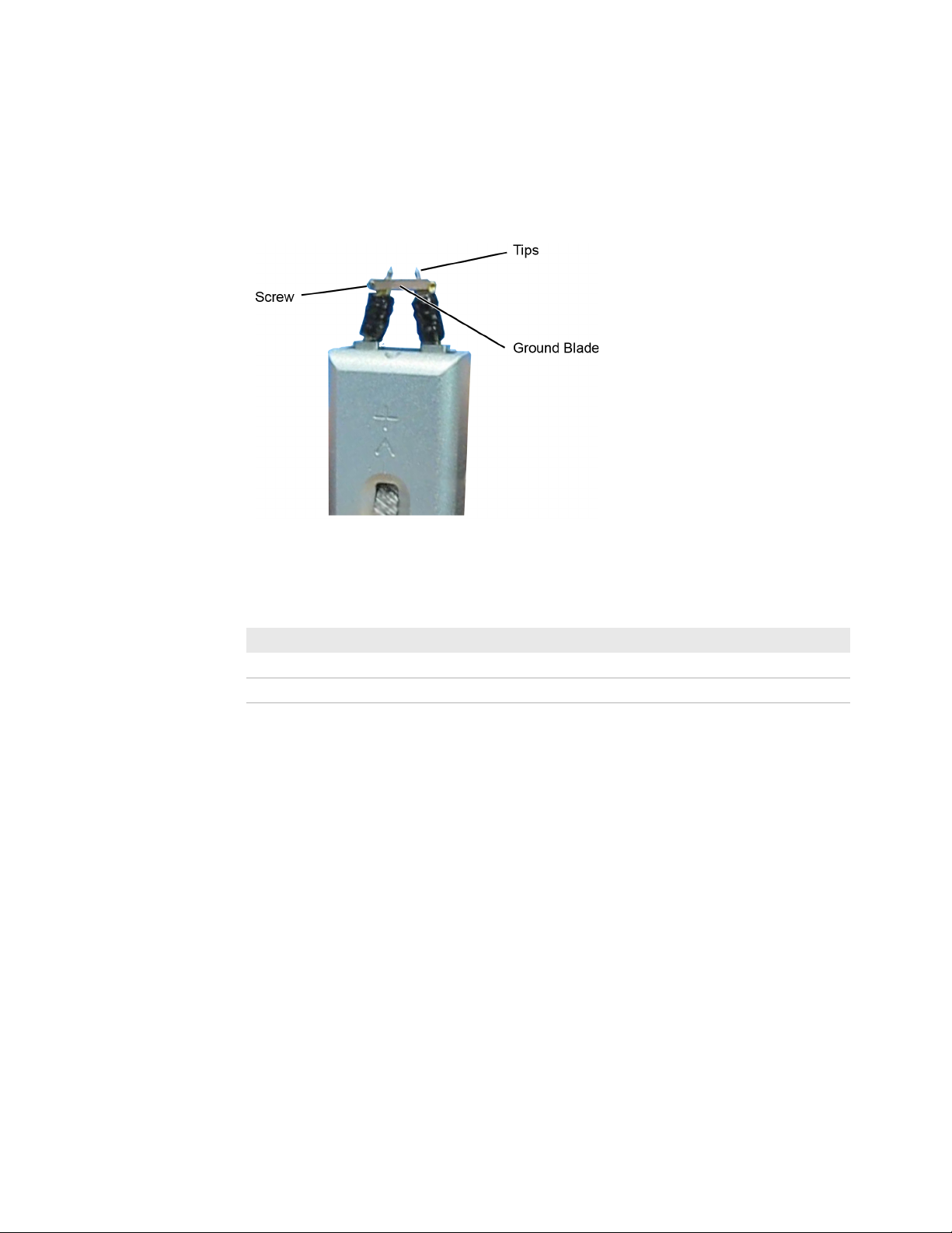
Figure 40 shows the replaceable parts for th N5445A.
Using InfiniiMax III+ Probe Heads 2
Figure 40 Browser Tips and Ground Blade
Table 12 N5445A Replaceable Parts
Description Qty Part Number
Browser tips 4 N5476A
Ground Blade 1 N4855A
Ground Blade Screws 1 N4856A
N2787A 3D Probe Positioner
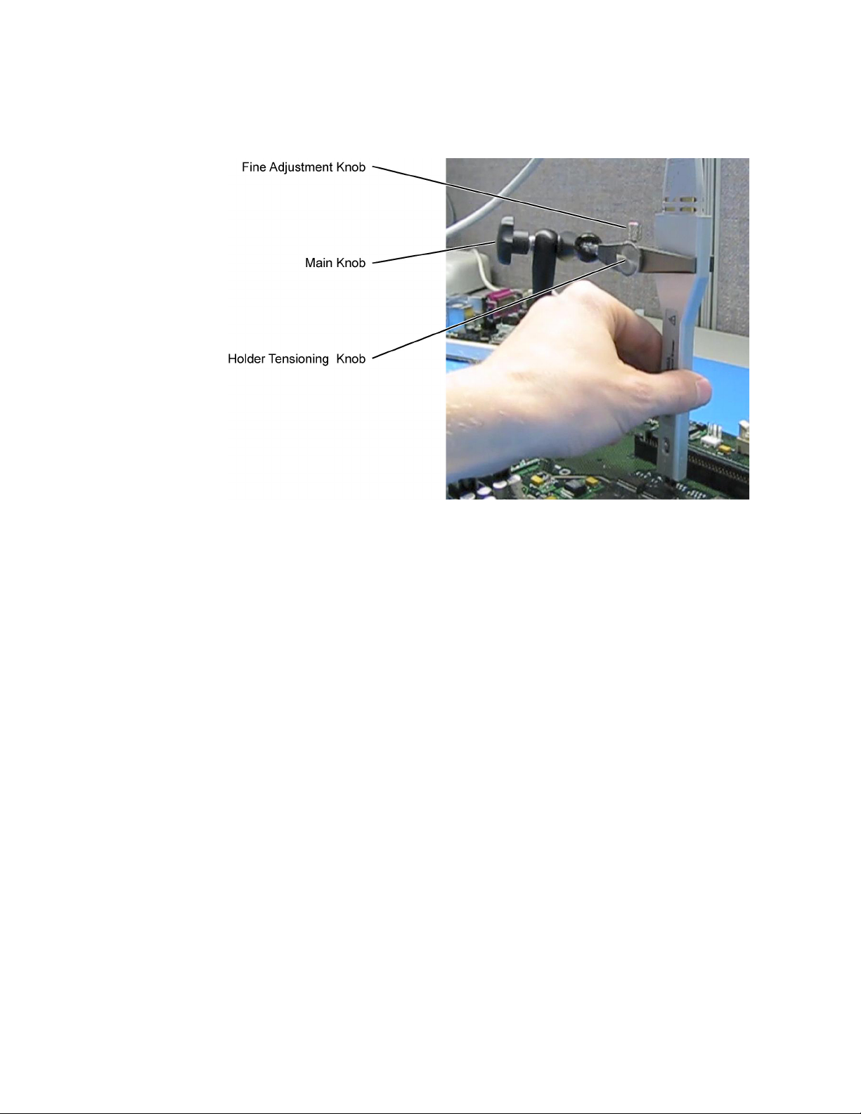
Using the N2787A 3D probe positioner with the N5445A browser probe head
reduces the chance of breaking the browser tips and ensures that the tips maintain
solid contact. Use the following steps to position the probe using the N2787A:
1 Lock the vertical compliance of the probe positioner.
2 Clamp the browser into the positioner, aligning the browser’s slot with the
positioner’s gripping pad.
3 While holding the browser, loosen the main knob and position the probe.
4 Use the browser’s own weight to depress the tips, and tighten the main knob to
lock the probe’s position.
InfiniiMax III+ Series Probes User’s Guide 57
Page 58
2 Using InfiniiMax III+ Probe Heads
Figure 41 Using the Browser with the N2787A 3D Probe Positioner
58 InfiniiMax III+ Series Probes User’s Guide
Page 59
Using InfiniiMax III+ Probe Heads 2
MX0109A
N2836A
MX0109A and N2836A InfiniiMode Solder-In Heads
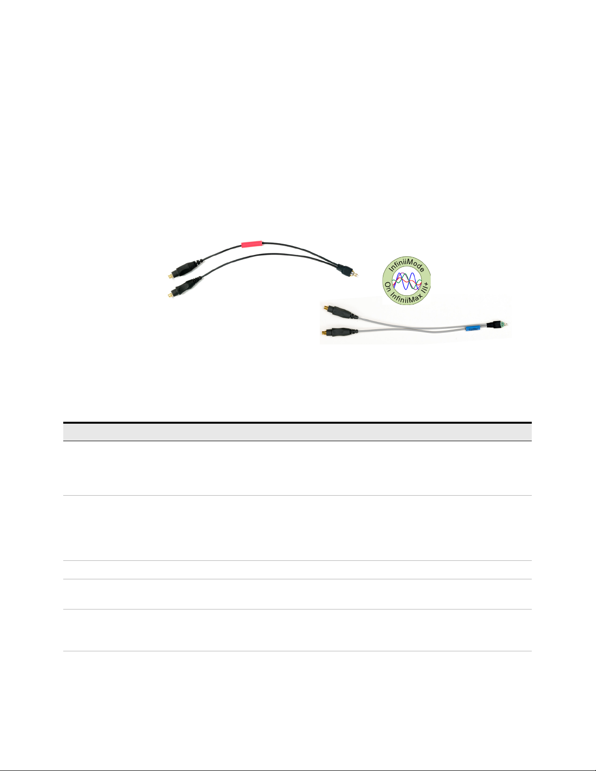
The following two solder-in probe heads are available for InfiniiMax III+ amplifiers.
• MX0109A Extreme Temperature Solder-in probe head
• N2836A InfiniiMax III+ Solder-in probe head
These probe heads are economical semi-permanent connections that provide up
to 26 GHz of system bandwidth.
Figure 42 MX0109A and N2836A InfiniiMax III solder-in probe heads
The following table highlights the key features of these probe heads.
MX0109A N2836A
Supports testing in extreme temperature ranges.
Can withstand –55°C to +150°C temperature range for up to 750
test cycles. Refer to the topic “Extreme Temperature Testing
with MX0109A Probe Head" on page 64 to know more.
InfiniiMode capable.(InfiniiMode allows you to make differential, common mode, and single ended measurements without
having to re-solder the tip leads. Because these are InfiniiMode compatible heads, the tip has two signal leads and two
ground leads. To learn about InfiniiMode, refer to “To Use InfiniiMode" on page 23. The ground leads have minimal effect
on differential measurements. However, if you are making only differential measurements, you can optionally cut off the
ground leads or fold them out of the way.
The span of leads can be adjusted from 5 mil - 250 mil (0.127 mm - 6.35 mm).
User replaceable resistor leads. To know how to install / repair resistor leads, refer to “Replacing Axial Resistor Tips" on
page 56.
MX0109A and N2836A have different S parameters stored in the oscilloscope’s firmware. On selecting the probe head in the
oscilloscope’s Select Probe Head dialog box, the appropriate S parameter file for the probe head is loaded. This file is used in
conjunction with the probe amplifier’s S parameters to compute the overall probe correction for your measurement case.
Can withstand –40°C to +85°C temperature range.
InfiniiMax III+ Series Probes User’s Guide 59
Page 60
2 Using InfiniiMax III+ Probe Heads
NOTE
NOTE
CAUTION
Ensuring Maximum Performance for MX0109A / N2836A Probe Heads
Tip Spacing
The specifications and performance plots of the MX0109A / N2836A probe heads
were measured with a nominal spacing of 40 mil (1 mm). In order to achieve the
proper response as shown in the performance plots, keep the mini-axial lead
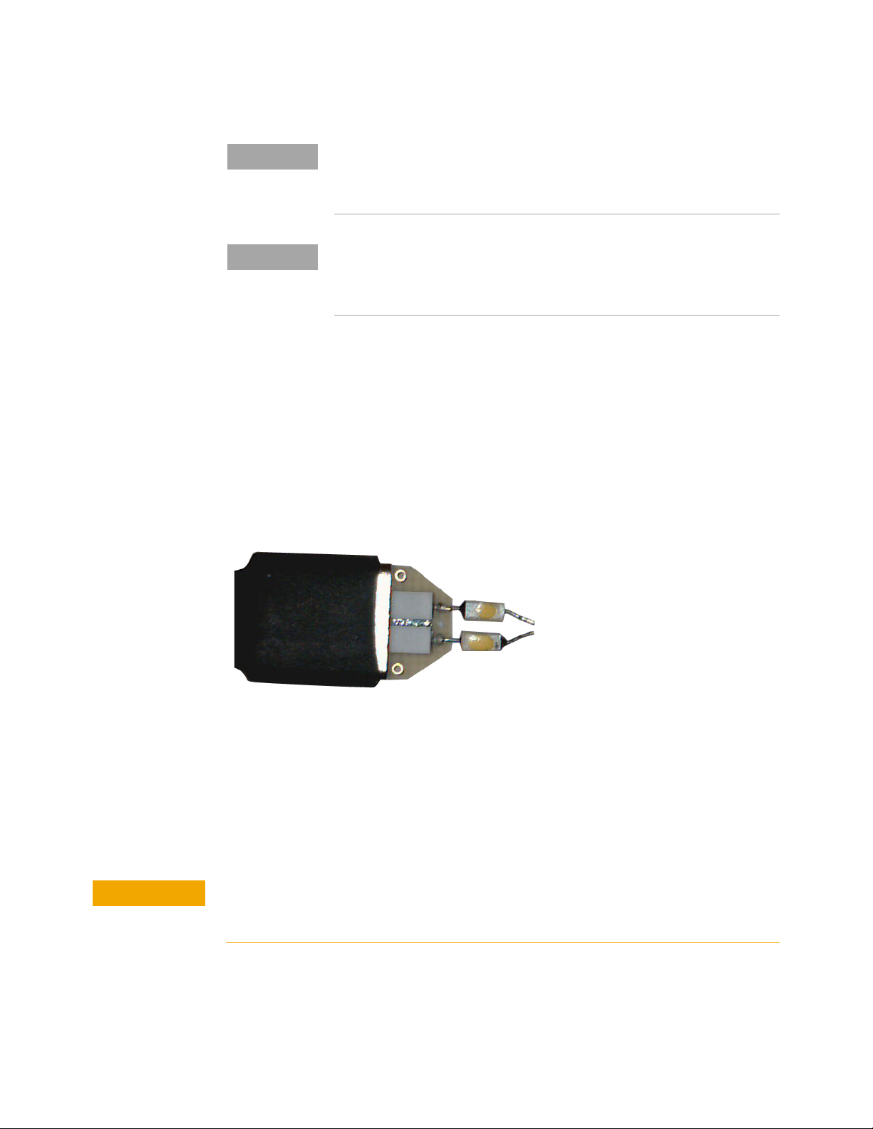
resistors roughly parallel as shown in Figure 43, and use the tip wires on the
mini-axial leads to get the desired span.
The minimum required Infiniium software version for the MX0109A probe head is as
follows:
- 10.10 or higher (for Infiniium UXR-Series oscilloscopes)
- 6.40 or higher (for all other compatible oscilloscopes)
Refer to Tabl e 20 on page 99 and Tab le 21 on page 100 to know about the
characteristics of these probe heads.
For performance plots, refer to “N2836A and MX0109A Solder-In Probe
Heads (Flat Orientation)" on page 114.
Figure 43 Proper Position of Resistors
If you need to position the mini-axial lead resistors different than shown in this
figure (that is, resistor bodies close together or spread way apart), use N2807A
and N2808A Precision Probe products to perform an AC calibration of the probe.
The AC calibration will properly capture the response. Increasing the spacing to
250 mil will degrade the performance some, but Precision Probe can be used to
compensate or qualify the effect.
The axial resistors on the MX0109A / N2836A solder-in probe heads are fragile. They
must be manufactured in this way in order to meet the high-performance, high
bandwidth applications they are intended for. Be careful when handling.
60 InfiniiMax III+ Series Probes User’s Guide
Page 61
Using InfiniiMax III+ Probe Heads 2
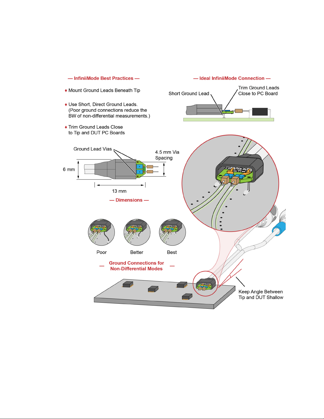
Best Practices for MX0109A and N2836A Connection to DUT
Figure 44 Probe Head Connection to DUT (InfiniiMode)
InfiniiMax III+ Series Probes User’s Guide 61
Page 62
2 Using InfiniiMax III+ Probe Heads
CAUTION
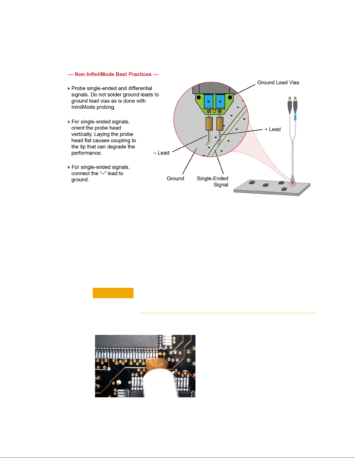
Figure 45 Probe Head Connection to DUT (Non-InfiniiMode)
Soldering the MX0109A / N2836A Probe Head to the DUT
Before using the following procedure, refer to “Soldering Tips" on page 76.
To solder the probe head to your DUT, complete the following steps. This
procedure does not show soldering the ground leads. but the same techniques as
described in this procedure are used.
Always mechanically strain-relieve the probe head to protect both
your probing equipment and DUT from damage. Refer to “Strain
Relieving the Probe Heads" on page 74.
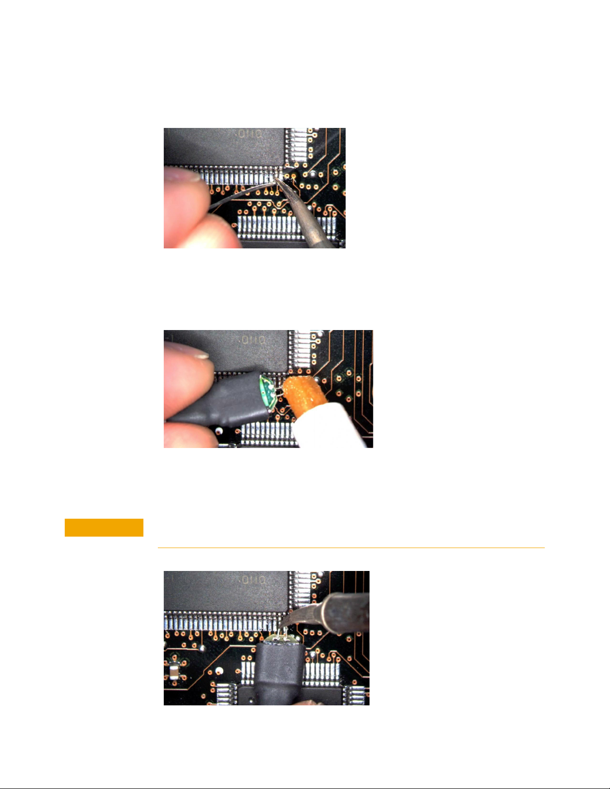
1 Apply flux to your target leads as shown in Figure 46.
Figure 46 Applying Flux
62 InfiniiMax III+ Series Probes User’s Guide
Page 63
Using InfiniiMax III+ Probe Heads 2
CAUTION
Tin the leads with a small amount of solder.
2
Figure 47 Tin the Leads
3 Use tweezers to form the probe head wires to fit your DUT’s geometry.
4 Flux the DUT leads and your probe head wires.
Figure 48 Applying Flux to Leads and Wires
5 Position the probe head wires on the DUT leads and quickly re-flow the solder
as shown in Figure 49.
Do not leave the iron in contact with the probe head for more than a few seconds at a
time.
Figure 49 Positioning Wires
InfiniiMax III+ Series Probes User’s Guide 63
Page 64
2 Using InfiniiMax III+ Probe Heads
CAUTION
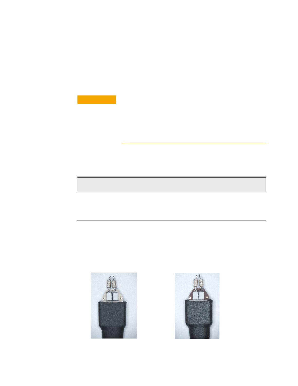
MX0109A - After usage under high
temperatures
MX0109A - Before usage under high
temperatures
Extreme Temperature Testing with MX0109A Probe Head
The MX0109A probe head can withstand temperatures from –55°C to +150°C
thereby making it suitable for extreme temperature environments such as
temperature chambers. For extreme temperature testing, use the MX0100A probe
head with the N5450B InfiniiMax extreme temperature extension cable.
To know more about the N5450B extension cable and cautions associated with
using an InfiniiMax probe head in extreme temperature testing, refer to ““N5450B
Extreme temperature cable extension kit" on page 33.
InfiniiMax probe amplifiers cannot withstand extreme
temperatures (–55°C to +150°C) that the MX0109A probe head
can withstand. Be cautious not to subject these probe amplifiers
to extreme temperatures. Using the N5450B extension cable with
the MX0109A probe head physically separates the amplifier from
the probe head and therefore eliminates the chances of the
amplifier’s exposure to extreme temperatures.
Probe Head
Configuration
MX0109A (attached to
the N5450B extension
cable)
Operating Temperature Range (oC) Expected Lifetime of
the Probe Head (cycles)
-55° C dwell, 1000 hours minimum
+150° C dwell, 1000 hours minimum
-55° C to 150° C cycles, 750 cycles minimum
(as per JEDEC JESD22-A104 revision E)
>750
The MX0109A probe head components may undergo discoloration when used
under high temperatures. Such changes do not, however, affect the probe head’s
performance or measurement quality. The probe head maintains its specified
frequency response and bandwidth over the operating temperature range (–55°C
to +150°C), without any need for compensation or correction.
64 InfiniiMax III+ Series Probes User’s Guide
Page 65
Using InfiniiMax III+ Probe Heads 2
CAUTION
NOTE
CAUTION
N5441A InfiniiMax III Solder-In Head (discontinued)
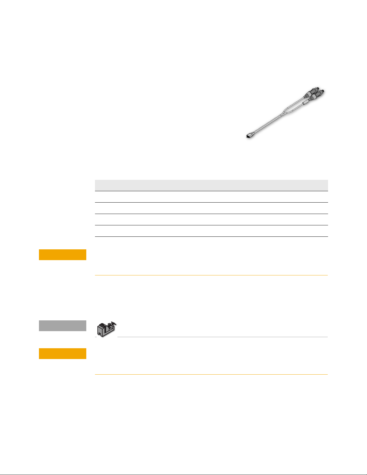
The N5441A InfiniiMax III solder-in
probe head is an economical semi-permanent
connection that provides up to 16 GHz of system
bandwidth. Variable span of the leads ranges from
5 mil to 80 mil (0.127 mm to 2 mm).
The N5441A probe head can be used with the
N5450B InfiniiMax extreme temperature extension
cable. This is the only InfiniiMax III probe head that
can withstand the –55°C to +150°C extreme
temperature range (for up to 250 test cycles).
Table 13 Bandwidth
Probe Amplifier BW Probe Amplifier BW
N2830A 4 GHz N7000A 8 GHz
N2831A 8 GHz N7001A 13 GHz
N2832A 13 GHz N7002A 16 GHz
N7003A 20 GHz
When using the N5450B extension cable, do not subject the InfiniiMax III probe
amplifier or probe head (other than the N5441A solder-in probe head) to extreme
temperatures.
Replaceable parts
Extra wire (for solder-in probe head only). 01169-81301 (7 mil), 01169-21306
(5 mil)
To install or repair N2838A resistor leads, refer to “Replacing N5441A Probe Head
Wires" on page 82.
The wires on the N5441A are fragile. They must be manufactured in this way in order
to meet the high-performance, high bandwidth applications they are intended for. Be
careful when handling.
InfiniiMax III+ Series Probes User’s Guide 65
Page 66
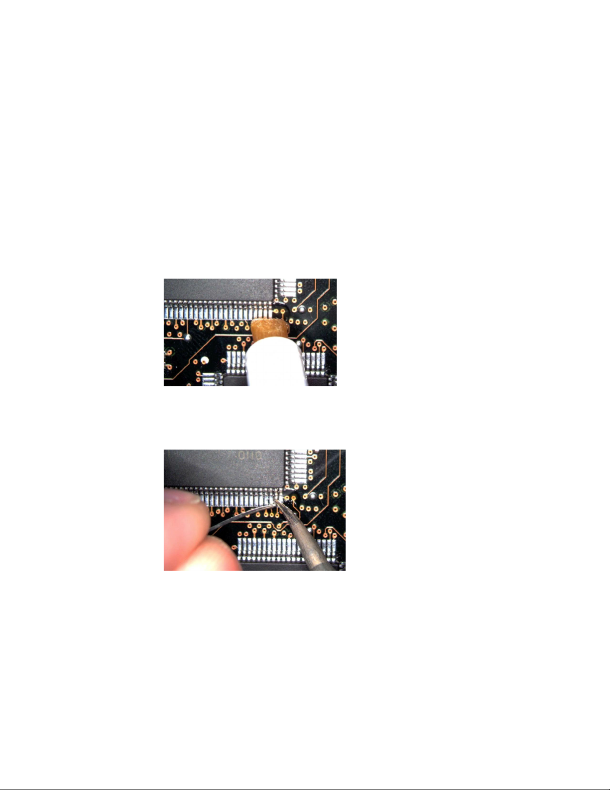
2 Using InfiniiMax III+ Probe Heads
Soldering the probe head to the DUT
Before using the following procedure, refer to “Soldering Tips" on page 76.
To solder the probe head to your DUT, complete the following steps. The
procedure is very similar to that for the ZIF probe tips used with the N5439A probe
head.
1 Position the probe head near the location on the DUT where you want to solder
the probe.
2 Add strain relieve for the probe head as described in “Strain Relieving the
Probe Heads" on page 74.
3 Apply flux to your target leads as shown in Figure 50.
Figure 50 Applying Flux
4 Tin the leads with a small amount of solder.
Figure 51 Tin the Leads
5 Use tweezers to form the probe head wires to fit your DUT’s geometry.
6 Flux the DUT leads and your probe head wires.
66 InfiniiMax III+ Series Probes User’s Guide
Page 67
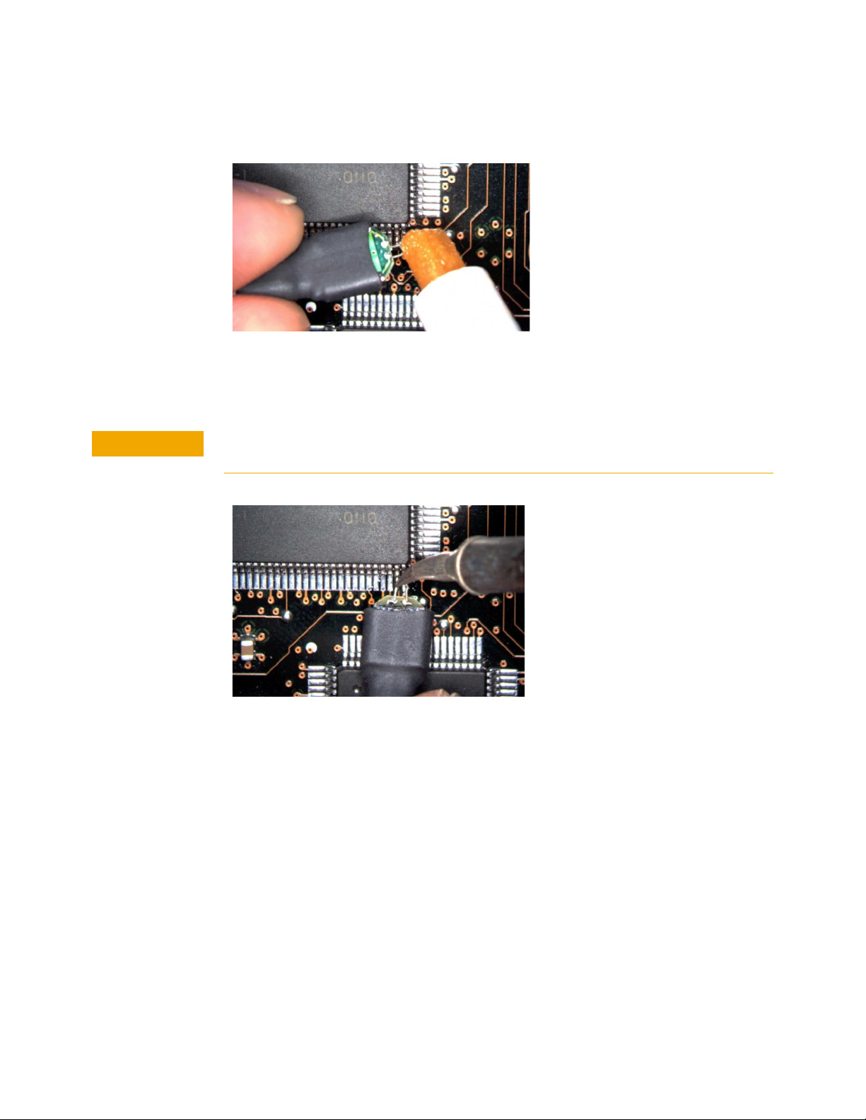
Using InfiniiMax III+ Probe Heads 2
CAUTION
Figure 52 Applying Flux to Leads and Wires
7 Position the probe head wires on the DUT leads and quickly re-flow the solder
as shown in Figure 53.
Do not leave the iron in contact with the probe head for more than a few seconds at a
time.
Figure 53 Positioning Wires
InfiniiMax III+ Series Probes User’s Guide 67
Page 68
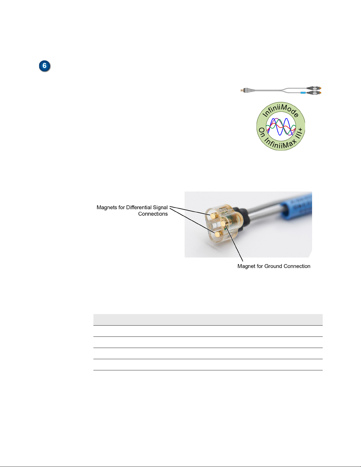
2 Using InfiniiMax III+ Probe Heads
N2848A QuickTip InfiniiMode Probe Head
The N2848A QuickTip probe head is used with an
N2849A QuickTip and together they provide the
following advantages:
• InfiniiMode on InfiniiMax III+ (N2830/1/2A and
N7000/1/2/3A probe amplifiers). InfiniiMode
allows you to make differential, common mode,
and single ended measurements without having
to re-solder the tip leads.
• Easy-to-make secure magnetic mechanical
connection between the probe head and
QuickTip. Three magnets in the head connect the two sides of a differential
signal and a ground. No latch lever is used!
Figure 54 Magnet Connections in Probe Head
• Extreme temperature environments such as temperature chambers.
Table 14 Bandwidth
Probe Amplifier BW Probe Amplifier BW
N2830A 4 GHz N7000A 8 GHz
N2831A 8 GHz N7001A 13 GHz
N2832A >12 GHz N7002A 16 GHz
N7003A >16 GHz
Permanently solder any number of QuickTips to your DUT as shown in Figure 55
on page 69. Because the probe head is magnetically connected (instead of
mechanically connected) to the QuickTip, you can effortlessly connect and
disconnect to each QuickTip. For best performance, position the QuickTip
vertically on the DUT. Because this is an InfiniiMode compatible head, the tip has
two signal leads and two ground leads. To learn about InfiniiMode, refer to “To Use
68 InfiniiMax III+ Series Probes User’s Guide
Page 69
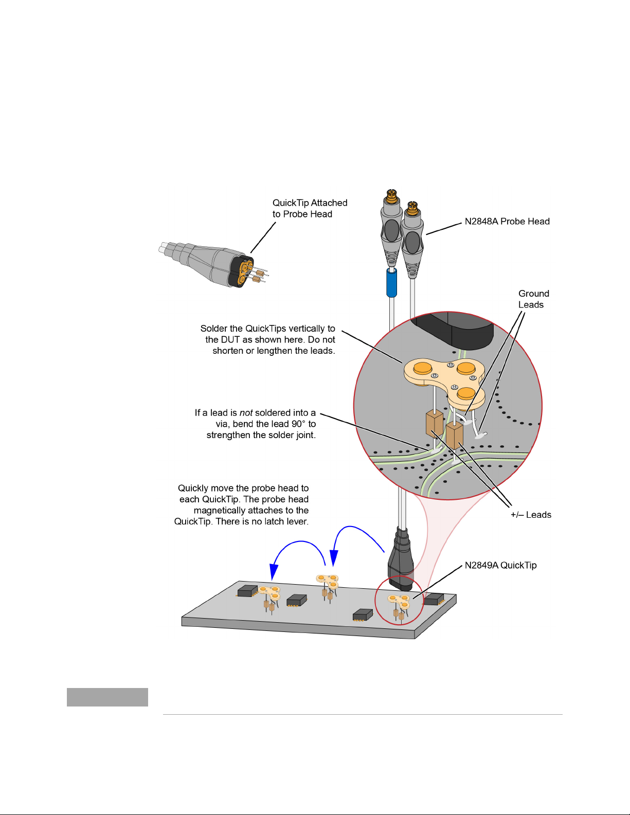
Using InfiniiMax III+ Probe Heads 2
NOTE
InfiniiMode" on page 23. The ground leads have minimal effect on your differential
measurements. However, if you are making only differential measurements you
can optionally cut off the ground leads or fold them out of the way. Be aware that
without the ground leads, the mechanical stability of the QuickTip will be reduced
and you will need to stabilize the probe head.
Figure 55 Probing with the N2848A Probe Head and QuickTip
N2849A QuickTips are also compatible with N2851A QuickTip Probe Heads, which are designed for
1130/1/2/4A InfiniiMax I and 1168/9A InfiniiMax II probes.
InfiniiMax III+ Series Probes User’s Guide 69
Page 70

2 Using InfiniiMax III+ Probe Heads
CAUTION
NOTE
NOTE
NOTE
CAUTION
NOTE
NOTE
CAUTION
CAUTION
Do not replace or repair the N2849A QuickTip’s resistor or ground leads. Attempting to
do so will damage the ability of the tip to mate with the N2848A probe head.
The N2848A does not include any N2849A QuickTips. The N2849A must be ordered
separately.
Before connecting the QuickTip head to the tip, use the tack-putty (N5439-65201) included
with the N2848A QuickTip probe head or the N2787A 3D probe positioner for securing the
probe amplifier to a rigid body near the DUT.
For performance plots, refer to Chapter 6, “Performance Plots.
Connecting a QuickTip to the DUT
Use the following tips when soldering the QuickTips to your DUT:
• Orient the QuickTip vertically as shown in Figure 55 on page 69.
• Solder the four leads to vias or surfaces.
Always mechanically strain-relieve the QuickTip head before using to protect both
your probe accessories and DUT from damage. Refer to “Strain Relieving the
Probe Heads" on page 74.
Resistor and wire leads on the QuickTip are factory trimmed to the proper length for use.
Adding wire length to the tip of the mini-axial lead resistors or to the ground leads will
degrade the performance of the probe.
Soldering the ground wires is not required when making differential or single-ended (+ or –
leads) measurements.
• When soldering to a via, always trim the lead close to the via’s underside.
• If a lead is to be soldered to a surface and not a via, make a stronger solder joint
by bending the end of the lead 90°. For signal leads, bend the wire
approximately half way between the resistor and the end of the wire. Bend the
ground leads at about the same distance.
Be careful not to damage the tip wires when handling the QuickTips. Wires can be
carefully reshaped with tweezers or fingers if necessary.
The QuickTips are very fragile. They must be manufactured in this way in order to meet
the high-performance, high bandwidth applications they are intended for. Be
extremely careful when handling.
70 InfiniiMax III+ Series Probes User’s Guide
Page 71
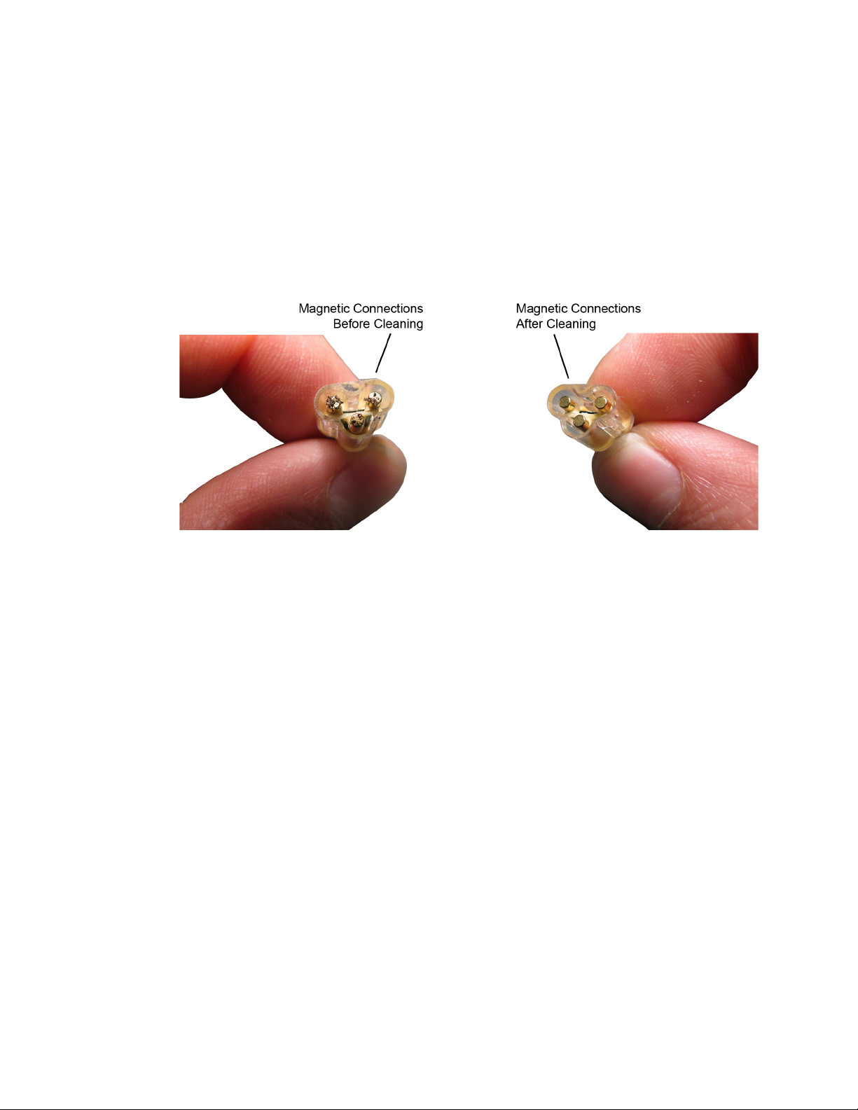
Cleaning the Magnetic Connections
If the three magnetic connections in the head become dirty, clean the connections
using the following steps:
1 Use compressed air or a cloth to remove any loose dirt.
2 Gently rub a small piece of tack putty (supplied with the probe) against the
magnetic connections to clean off any remaining surface grime.
Using InfiniiMax III+ Probe Heads 2
Figure 56 N2848A Head Before and After Cleaning
InfiniiMax III+ Series Probes User’s Guide 71
Page 72
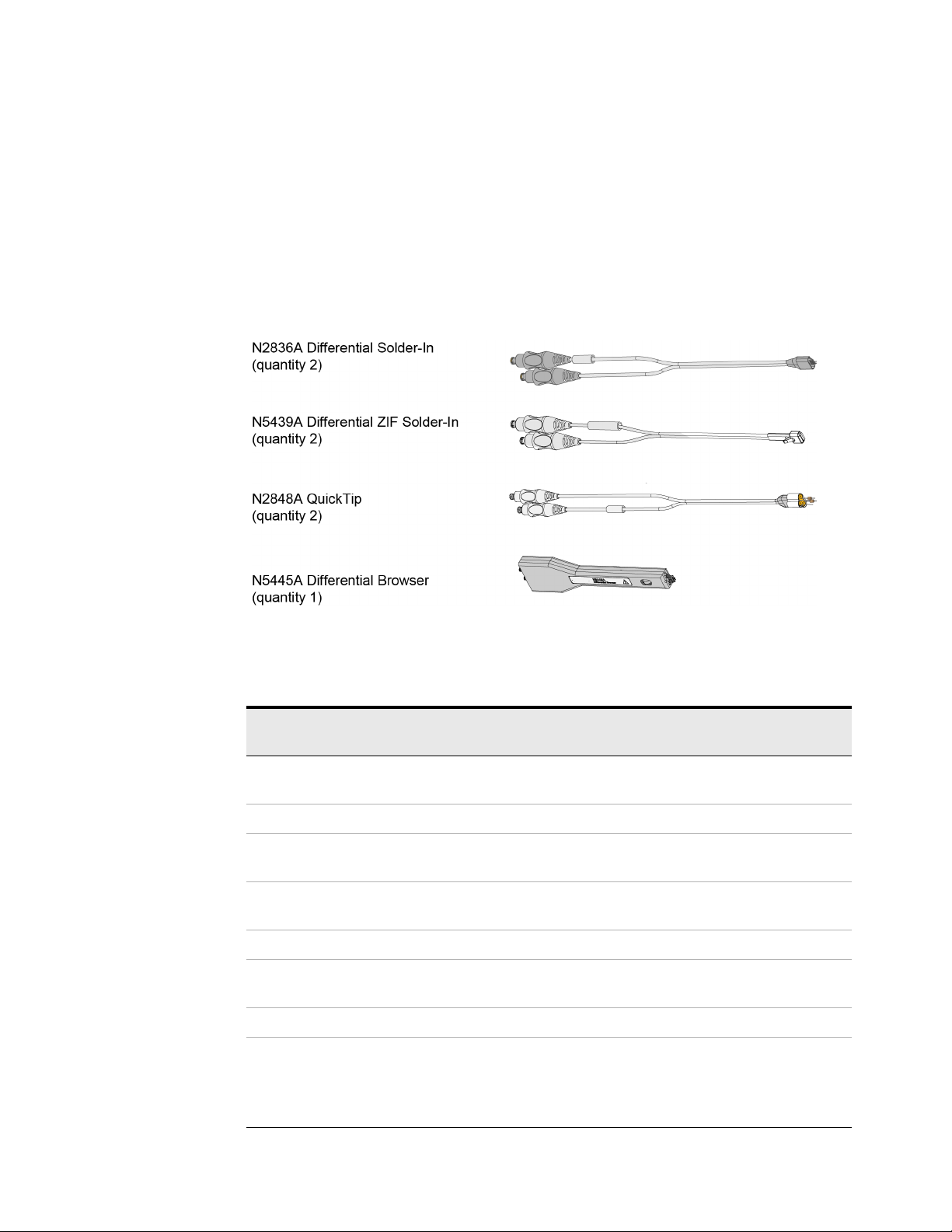
2 Using InfiniiMax III+ Probe Heads
N2835A InfiniiMax III+ Differential Connectivity Kit and Accessories
In addition to the individual probe heads described in the previous topics, the
N2835A differential connectivity kit is also available for the InfiniiMax III+ probes.
This kit provides multiple quantities of the four InfiniiMax III+ probe heads as
shown in Figure 57. You can order this kit either at the same time as InfiniiMax III+
probe amplifiers or separately later.
Figure 57 Probe Heads Included in the N2835A Differential Connectivity Kit (not to scale)
Table 15 Supplied Accessories (Sheet 1 of 2)
Qty
Description
N2836A InfiniiMax III 26 GHz Differential Solder-In Probe
Head
Replacement Axial Resistors Kit 10 N2836-68701
N5439A InfiniiMax III 28 GHz Differential ZIF Solder-in Probe
Head
N2838A InfiniiMax III 25 GHz ZIF Tip Kit 2 kits (5 tips in
N2848A InfiniiMax III QuickTip Probe Head 2 N2848A
N2849A InfiniiMax QuickTip Tips Kit 2 kits (4 tips in
N5445A InfiniiMax III Browser Probe Head 1 N5445A
Replacement Tips
Tweezer for replacing tips
Screw Driver
Protective End Cap
Supplied
2 N2836A
2 N5439A
each kit)
each kit)
4
1
1
1
Part
Number
N2838A
N2849A
N5476A
N5445-23801
N5445-23802
N5445-44101
72 InfiniiMax III+ Series Probes User’s Guide
Page 73

Table 15 Supplied Accessories (Sheet 2 of 2)
Using InfiniiMax III+ Probe Heads 2
Description
Qty
Supplied
Ground Blades 4 N5445-68700
Part
Number
InfiniiMax III+ Series Probes User’s Guide 73
Page 74
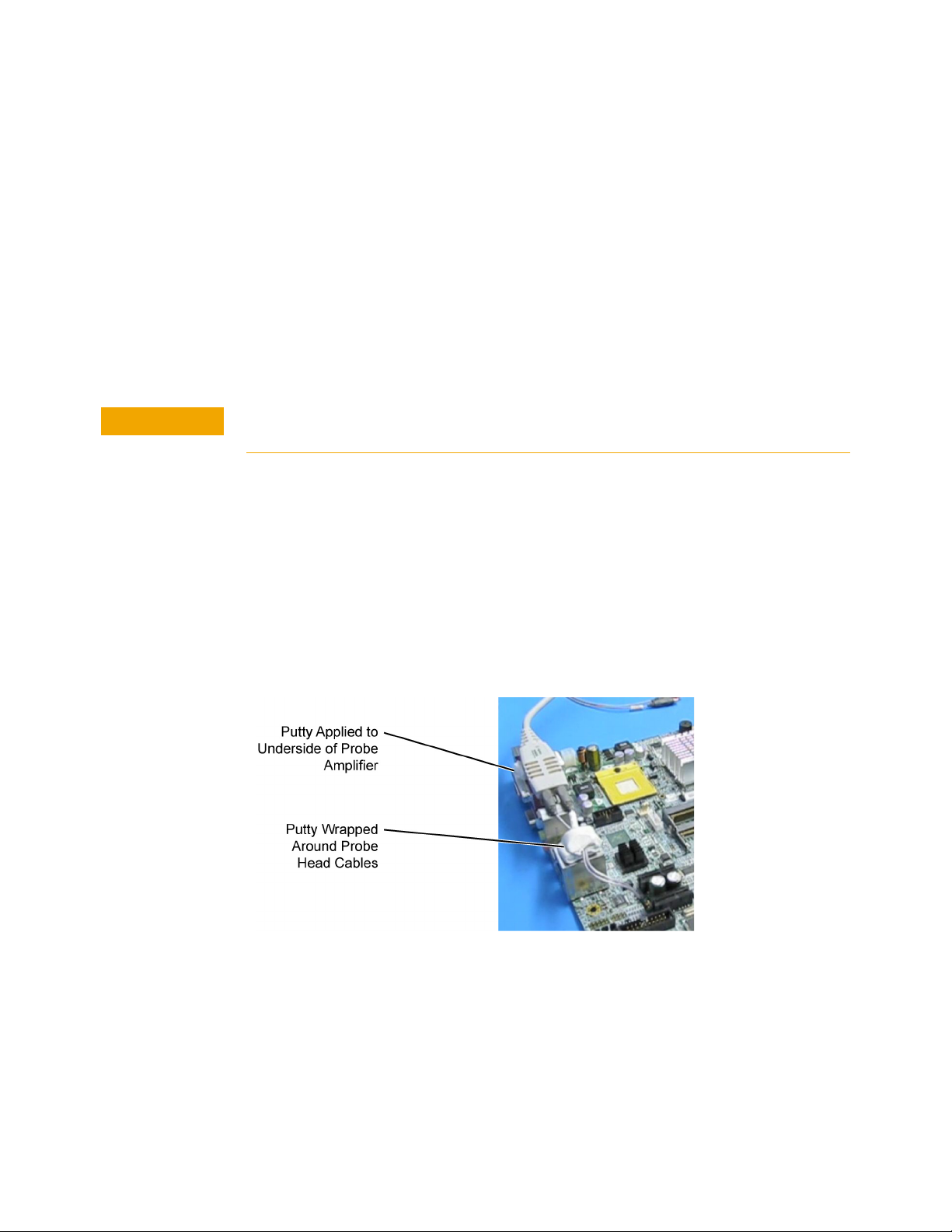
2 Using InfiniiMax III+ Probe Heads
CAUTION
Strain Relieving the Probe Heads
High-performance probes have small physical geometries to ensure the lowest
possible loading and best electrical response. Because of their small size, probing
accessories are often delicate. It is important to mechanically secure your probes
to protect both your equipment and designs from damage. Although tack putty
and low-temperature hot glue are recommended, you can also use other methods
such as tape or hook-and-loop strain relief. Keep in mind that different accessories
have different cable stiffness. You should choose a strain relief method appropriate
for the cable stiffness. For instance, it is best to secure the stiffer N5439A near the
SMP connectors and form the cable to the optimal location.
Do not kink cables. Do not crush cables. Do not use aggressive adhesives or high
temperatures.
Tack-putt y
Keysight recommends the use of tack putty for securing both probe heads and
amplifiers. Tack putty can be ordered using part number N5439-65201. Wrap a
small amount of tack-putty around your probe head cables, taking care to not
pinch them. The mass can then be secured to a rigid body neat your DUT.
Similar techniques can be used to secure probe amplifiers where you apply some
tack-putty to the underside of the probe amplifier body and attach it to a rigid
body near your DUT.
Figure 58 Probe Secured Using Tack Putty
You can also use putty with a positioner, such as the N2787A as shown in
Figure 59.
74 InfiniiMax III+ Series Probes User’s Guide
Page 75
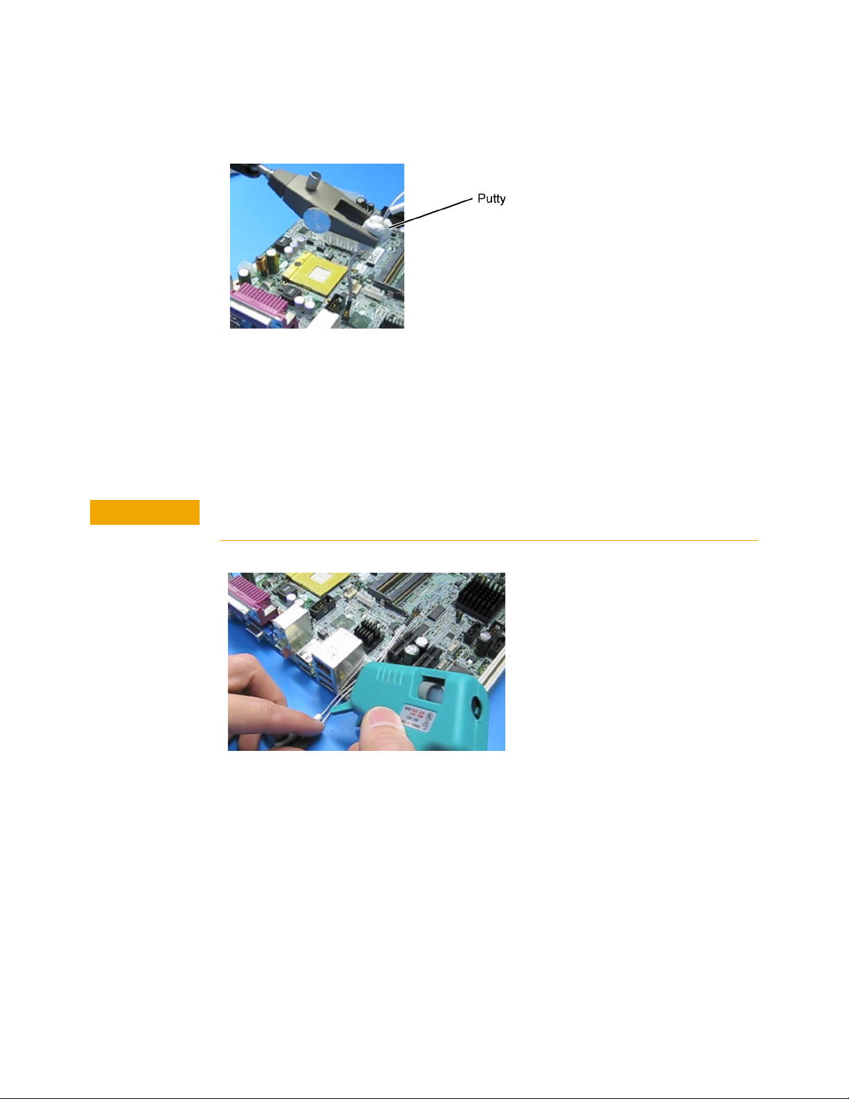
Figure 59 Using Putty With the N2787A 3D Probe Positioner
CAUTION
The same positioner can also be used to support your probe amplifier as shown in
Figure 41 on page 58.
Low-temperature hot glue
You can also use low-temperature hot glue to secure cables.
Using InfiniiMax III+ Probe Heads 2
Only use low-temperature hot glue. To remove the hot glue, warm it with a heat gun
set on low. Only heat the hot glue enough to remove it.
Figure 60 Probe Secured Using Low-Temperature Hot Glue
InfiniiMax III+ Series Probes User’s Guide 75
Page 76
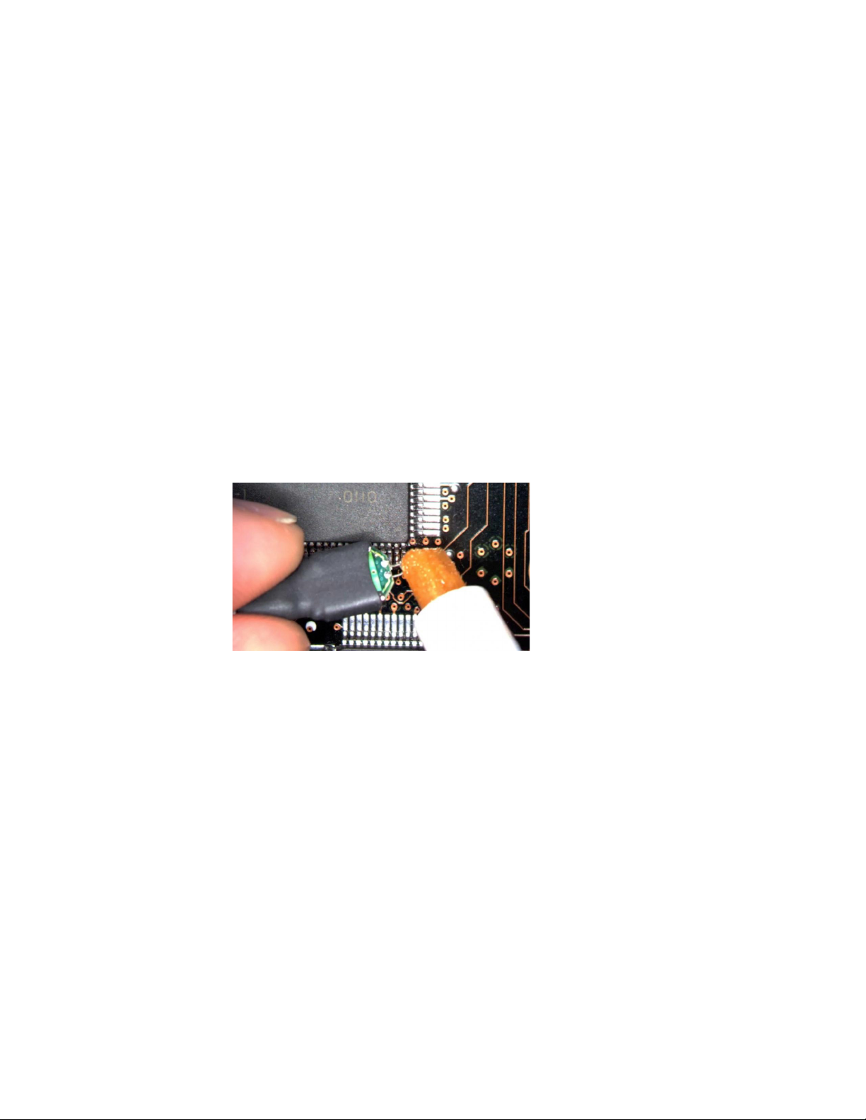
2 Using InfiniiMax III+ Probe Heads
Soldering Tips
When using the N5441A and N2836A solder-in heads and N5439A ZIF probe
heads, be sure to observe the following guidelines. For more information, refer to
the user’s guide.
• Use a temperature-controlled soldering iron station, if possible.
• Set the temperature of the soldering iron’s tip to between 370° C and 420° C
(for non RoHS standards).
• Use the smallest tip possible.
• Use an optical aid of some sort (microscope preferred).
• Employ minimal dwell times on the solder joint (< 2 seconds).
• Solder only the tip of the wire onto your DUT. The solder should not get close to
the existing solder ball on the tip.
• Use enough flux when soldering the tips into a DUT.
Figure 61 Applying Flux to Leads and Wires
76 InfiniiMax III+ Series Probes User’s Guide
Page 77

Keysight InfiniiMax III+ Series Probes
CAUTION
User’s Guide
3 Maintaining Probe Heads
Replacing Axial Resistor Tips 78
Replacing N5441A Probe Head Wires 82
Many probe heads come equipped with replaceable resistor or wire tips which can be
replaced or repaired. Using the procedures in this chapter, you can extend the life of the
following items:
• MX0109A probe heads
• N2836A probe heads
• N5441A probe heads
• N2838A ZIF tips
Do not replace or repair the N2849A QuickTip’s resistor or ground leads. Attempting to
do so will damage the ability of the tip to mate with the N2848A probe head.
77
Page 78

3 Maintaining Probe Heads
NOTE
CAUTION
CAUTION
Replacing Axial Resistor Tips
The procedure in this sections shows you how to replace the 130 ohm axial
resistors that are located at the tip of the:
• MX0109A extreme temperature solder-in probe head
• N2836A solder-in probe head and
• N2838A ZIF tip
These resistors can become worn or damaged with use. Order the replacement
axial resistor kit (N2836-68701) which provides 10 resistors.
The pictures in the following procedure show the N2836A solder-in probe head, but the same
procedure applies to the MX0109A and N2838A ZIF tip.
Recommended equipment
• Vise or clamp for holding tip.
Procedure
• Metcal STTC-022 (600 °C) or STTC-122(700 °C) tip soldering iron or equivalent.
The 600 °C tip will help limit burning of the FR4 tip PC board.
• 0.381 mm (0.015 in) diameter RMA flux standard tin/lead solder wire.
• Fine stainless steel tweezers.
• Rosin flux pencil, RMA type (Kester #186 or equivalent).
•Diagonal cutters.
• Magnifier or low power microscope.
•Ruler.
As the probe heads and tips are easily damaged, only experienced soldering
technicians should attempt this repair.
1 As shown in Figure 62, clamp the probe head or ZIF tip in a vise. Tweezers can
be used to hold the probe head or ZIF tip away from the vise. When using
tweezers, grip the tip either on the sides or top and bottom.
When tightening the vise, use light force to avoid damaging the solder-in probe head.
78 InfiniiMax III+ Series Probes User’s Guide
Page 79
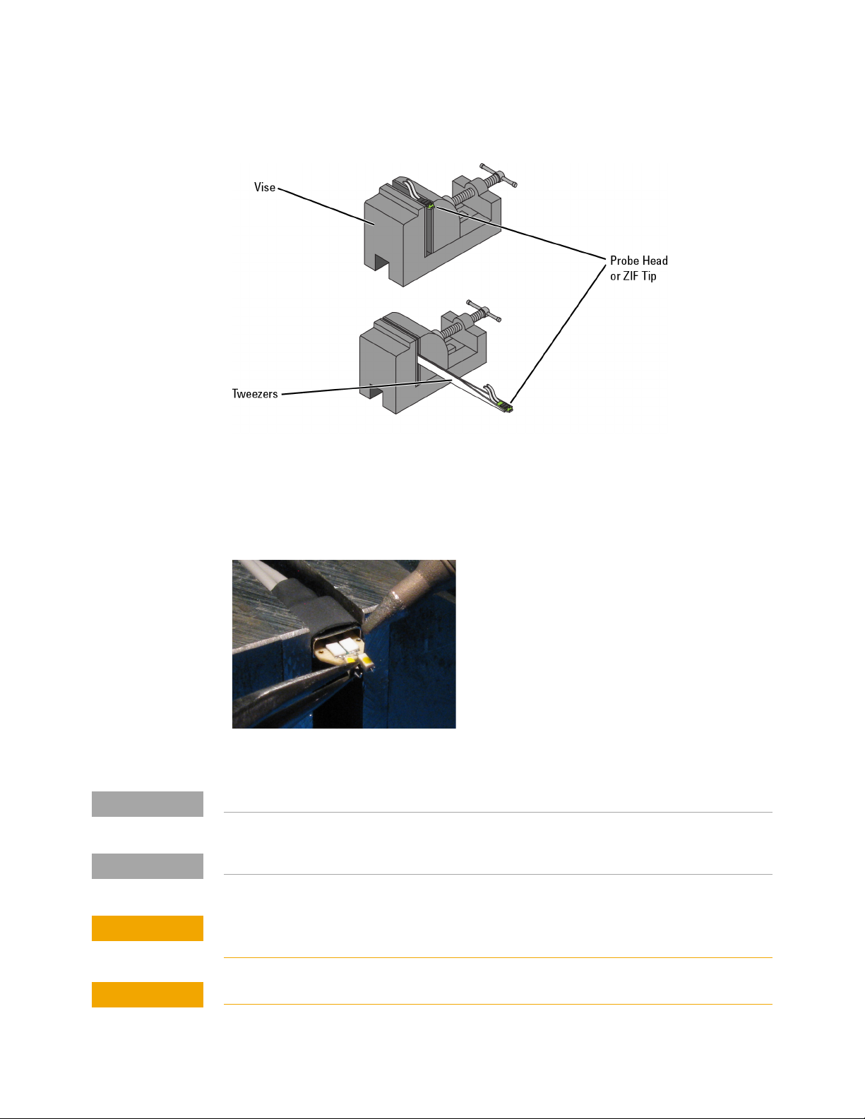
Figure 62 Clamping the Part
NOTE
NOTE
CAUTION
CAUTION
Maintaining Probe Heads 3
2 Grab each resistor lead or wire with tweezers and pull very gently up. Touch the
soldering iron to solder joint just long enough for the resistor to come free of
the probe head tip.
Figure 63 Removing the Resistor
Clean the soldering iron tip of any excess solder before using.
The solder joint has very low thermal mass so the joint will quickly melt and release.
To limit burning and damage to the PC board, do not keep the soldering iron in contact
with the tip any longer than is necessary.
Excessive dwell time with the iron will permanently damage the flip-chip resistor.
InfiniiMax III+ Series Probes User’s Guide 79
Page 80
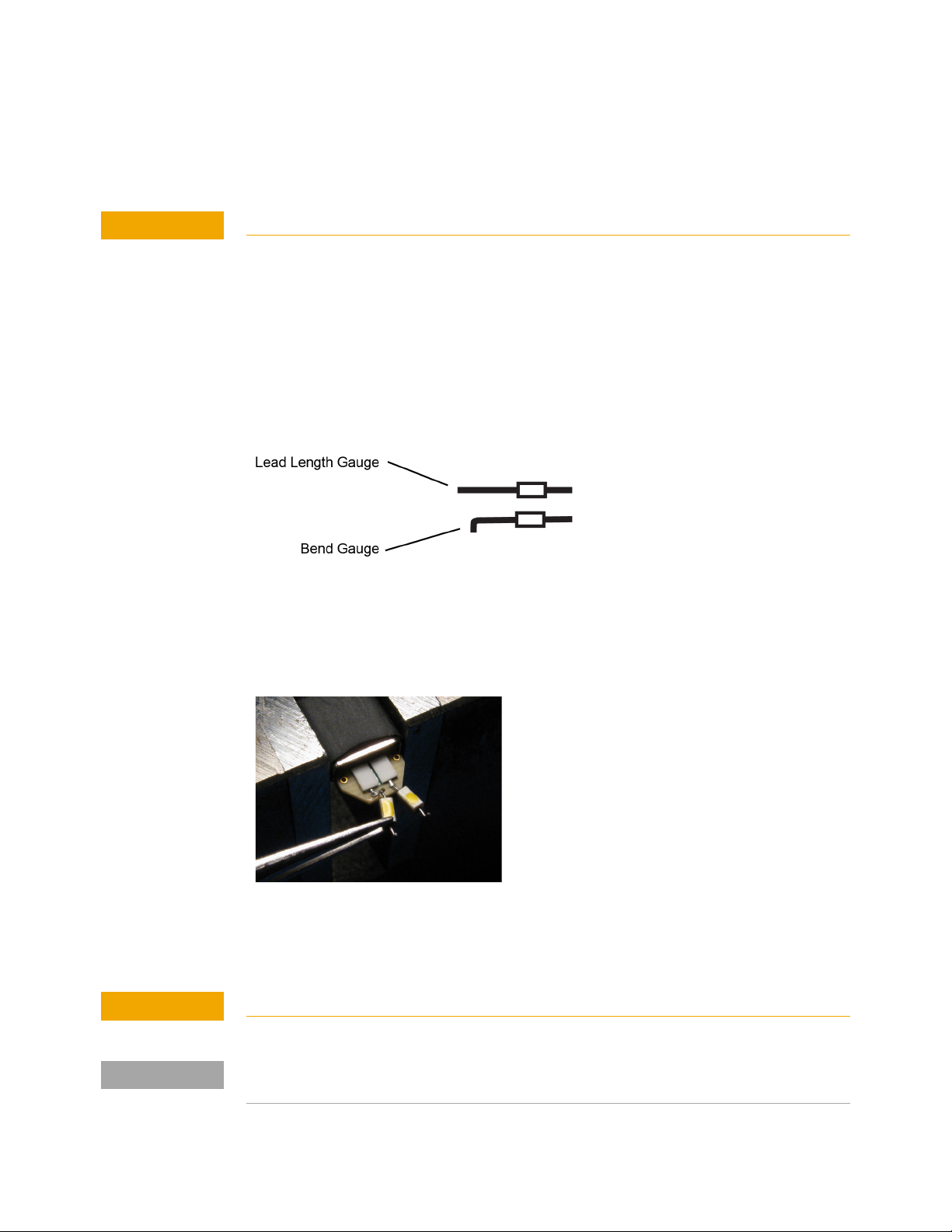
3 Maintaining Probe Heads
CAUTION
CAUTION
NOTE
3
Do not leave the iron in contact with the tip any longer than necessary.
4 Use the flux pencil to coat the solder joint area with flux.
5 Locate the trim gauge which is supplied with the N2836-68701 replacement
Use the soldering iron and solder to fill the holes in preparation for mounting
the new resistors (or wires).
axial resistor kit.
a Place a resistor over the lead length gauge shown in Figure 64. Trim the
leads to match the drawing. The orientation of the lead is not important.
b Place a resistor over the bend gauge and bend the leads to match the
drawing. This bend fits in the hole in the tip’s PC board.
Figure 64 Trim Guage
6 Holding the resistor lead or wire in one hand and soldering iron in the other,
position the end of the resistor lead (after the 90 degree bend) over the solder
filled hole.
Figure 65 Soldering in a new axial resistor
7 Touch the soldering iron to the side of the hole. When the solder in the hole
melts, the resistor lead will fall into the hole.
Remove the soldering iron as soon as the lead falls into the hole.
Because the thermal mass of the joint is very small, extra dwell time with the soldering iron is
not needed to ensure a good joint.
80 InfiniiMax III+ Series Probes User’s Guide
Page 81

Maintaining Probe Heads 3
Using a digital volt meter, measure the resistance from the coax center
8
conductor to the resistor tip. The DC resistance should measure 450 ohms.
InfiniiMax III+ Series Probes User’s Guide 81
Page 82

3 Maintaining Probe Heads
CAUTION
Replacing N5441A Probe Head Wires
Use the following procedure to install or replace the wire leads on the N5441A
solder-in probe head. Depending on your probing application, you can order either
5 mil or 7 mil wire as listed in the following table. For example, use the 5 mil wire
for attaching to small vias.
Table 16 Required Wire Type
Wire Diameter Part Number
0.007 inch (tin-plated nickel wires) 01169-81301
0.005 inch (tin-plated nickel wires) 01169-21306
Table 17 Recommended Equipment
Equipment
Vise or clamp for holding tip
Metcal STTC-022 (600 °C) or STTC-122 (700 °C) tip soldering iron or equivalent. The 600 °C tip will help limit burning of the
FR4 tip PC board.
0.381 mm (0.015 in) diameter RMA flux standard tin/lead solder wire
Fine stainless steel tweezers
Rosin flux pencil, RMA type (Kester #186 or equivalent)
Flush cutting wire cutters
Magnifier or low power microscope
Keysight supplied trim gauge (01169-23801)
Procedure
1 Use the vise or clamp to position the tip an inch or so off the work surface for
easy access.
If using a vise, grip the tip on the sides with light force. When tightening the vise, use
light force to avoid damaging the solder-in probe head If using a tweezers clamp, grip
the tip either on the sides or at the top and bottom.
82 InfiniiMax III+ Series Probes User’s Guide
Page 83
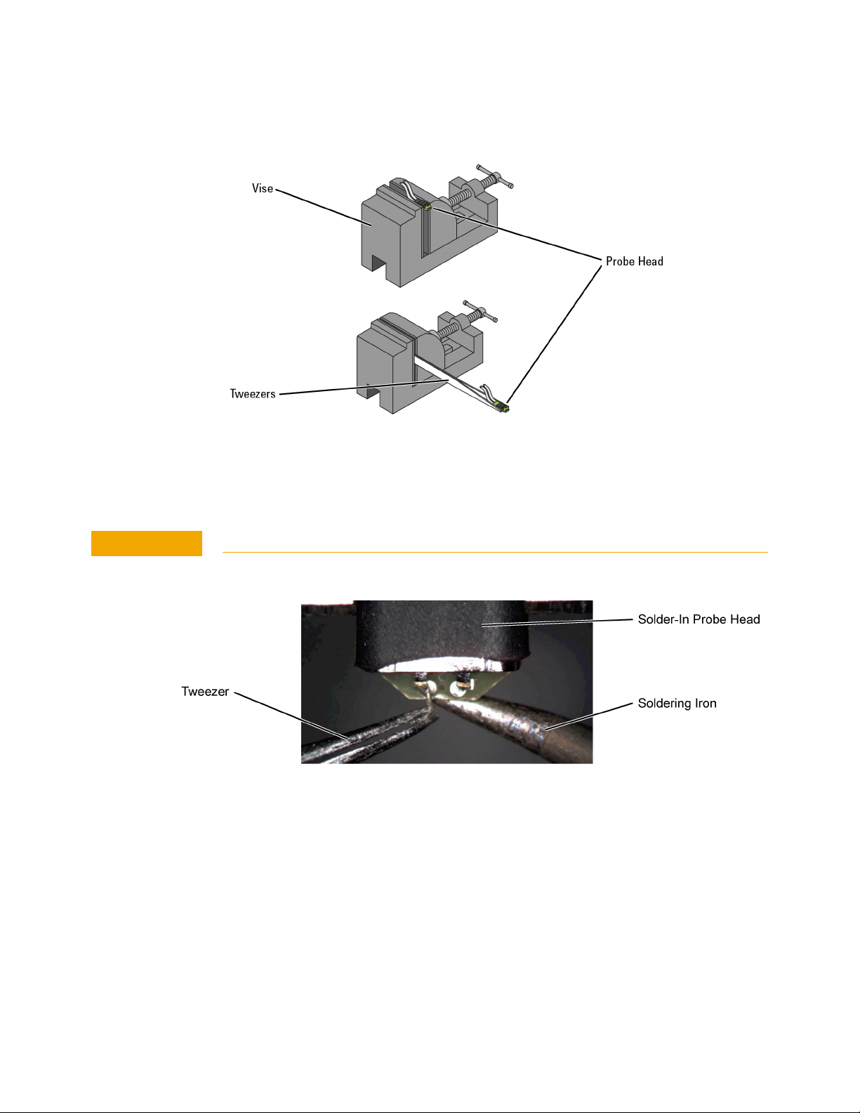
Figure 66 Clamping the Probe Head
CAUTION
Maintaining Probe Heads 3
2 As shown in Figure 67, remove the old wires with tweezers while re-flowing the
solder from the underside of the probe.
Apply heat quickly to avoid damaging your probe.
Figure 67 Removing the Old Wire
3 If necessary, add a small amount of solder to the holes and apply flux.
InfiniiMax III+ Series Probes User’s Guide 83
Page 84
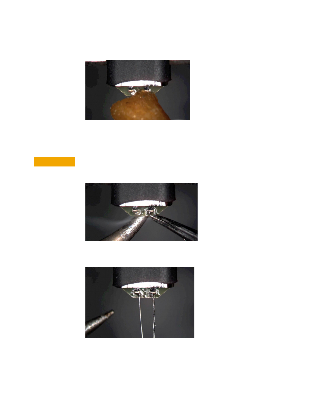
3 Maintaining Probe Heads
CAUTION
Figure 68 Adding Solder and Flux
4 Re-flow the solder from the underside and insert a new piece of wire. It is best
Do not dwell with the iron in contact with the probe head.
to shape the wire into an “L” before attempting to insert.
Figure 69 Adding a New Wire
Figure 70 New Wires Properly Attached
5 Trim any wire stubs on the probe head underside.
84 InfiniiMax III+ Series Probes User’s Guide
Page 85
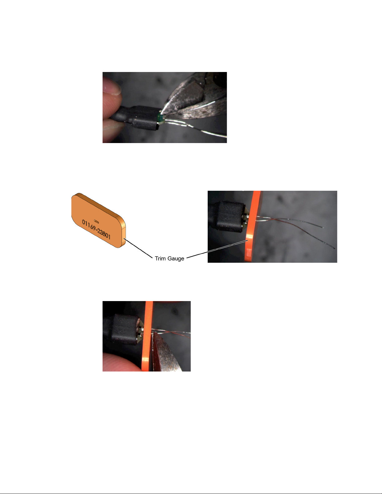
Maintaining Probe Heads 3
Figure 71 Trim Wire Stubs
6 Use the included trim gauge to cut the wire lengths. Doing so ensures the best
performance from your probe head.
Figure 72 Trim Gauge Placed on Wires
Figure 73 Removing Excess Wire
7 Check the DC resistance of each probe leg when you have replaced the wires.
The correct resistance should be 450 ohms.
InfiniiMax III+ Series Probes User’s Guide 85
Page 86

3 Maintaining Probe Heads
86 InfiniiMax III+ Series Probes User’s Guide
Page 87
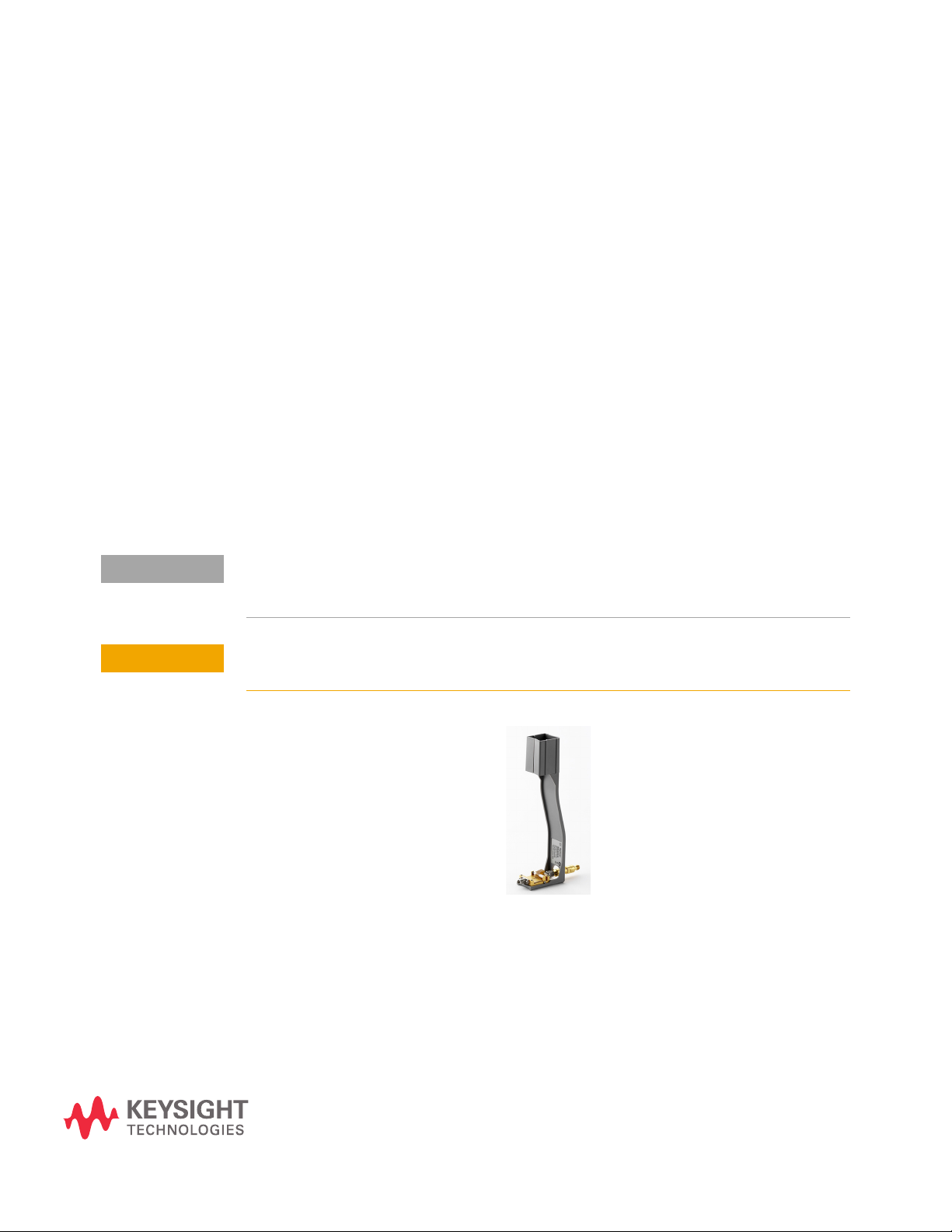
Keysight InfiniiMax III+ Series Probes
NOTE
CAUTION
User’s Guide
4 Calibration / Deskew
Procedure
The Calibration/Deskew procedure described in this chapter is applicable to both
N2830/1/2A and N7000/1/2/3A InfiniiMax III+ probes.
The probe calibration and deskew is a guided procedure that you start from the
oscilloscope’s Probe Calibration dialog box. Depending on the oscilloscope model,
you will be instructed to connect the probe head to either of the following
oscilloscope outputs:
•Front-panel Probe Comp terminals
• Aux Out BNC connector or Cal Out connector using the N5443A
Calibration/Deskew Fixture with 50W termination.
The N5443A fixture promotes the properly position the probe head during the procedure. If
you prefer, you can remove the plastic holder from the fixture by removing the four screws on
the bottom side of the holder.
Always wear an ESD wrist strap when working with active probes. Not doing so can
result in the probe becoming permanently damaged.
87
Page 88
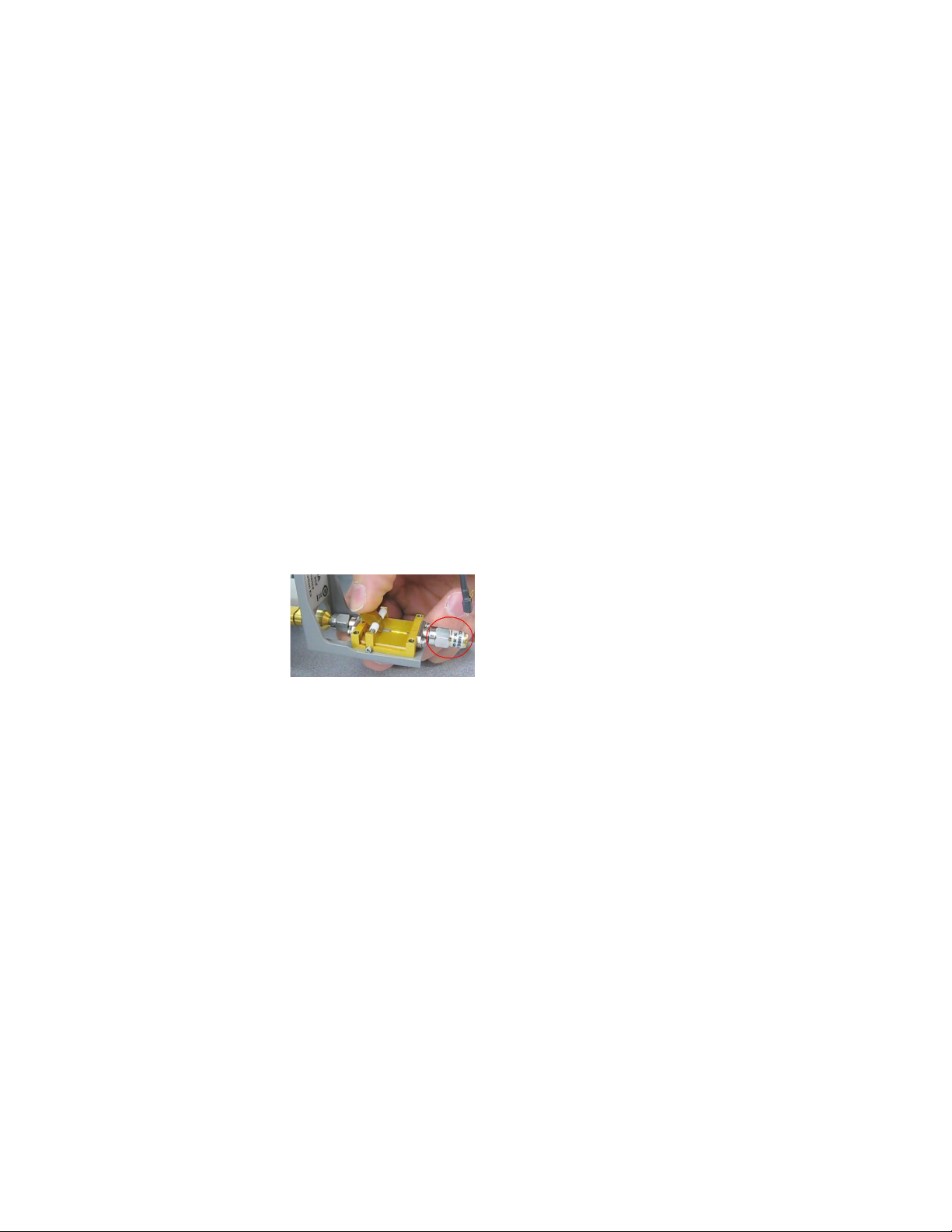
4 Calibration / Deskew Procedure
Procedure
The procedure is applicable to both N2830/1/2A and N7000/1/2/3A InfiniiMax III+
probes.
1 Connect the InfiniiMax III+ probe to an oscilloscope channel.
2 On the oscilloscope menu, click Setup > Probe Calibration. If you have an
N7000/1/2/3A probe, you can press the probe’s Menu button instead to access
the guided calibration procedure.
3 In the dialog box, select the tab that represents the channel for the probe being
tested. In the dialog box, click Start Atten/Offset Cal….
4 The dialog box indicates that you can use the oscilloscope’s Probe Comp
terminals or the oscilloscope’s Cal Out or Aux Out connector for the calibration. If
you are using the Probe Comp, touch the probe head’s leads to the Probe Comp
terminals. If you are using the Cal Out (or Aux Out) connector, use the N5443A
fixture as shown in the following steps:
a Connect a 50 ohm termination to the fixture as shown in Figure 74. The
termination is provided with the N5443A.
Figure 74 50W Terminator on N5443A
b As described in the dialog box, connect the fixture to the Cal Out or Aux Out
connector. Turn the nut on the Cal Out counter-clockwise to tighten as
shown in Figure 75.
c While holding the fixture upright with one hand, use an 8 in. lbs. torque
wrench to fully tighten the connector as shown in Figure 76.
d Detach the probe head from the probe and Insert the probe into the top of
the fixture holder as shown in Figure 77. The probe can slide up and down in
the holder to adjust the probe head position.
88 InfiniiMax III+ Series Probes User’s Guide
Page 89
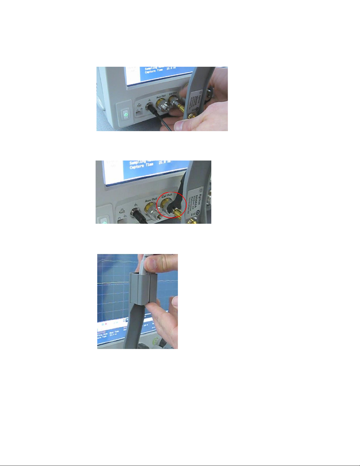
Figure 75 Attaching the N5443A Fixture
Calibration / Deskew Procedure 4
Figure 76 Tighten to 8 in. lbs.
Figure 77 Inserting the Probe Head
e Form the N5439A probe head ZIF tip wires as shown Figure 78. If you are
using the browser probe head, you do not need to adjust the shape of the
tips.
InfiniiMax III+ Series Probes User’s Guide 89
Page 90
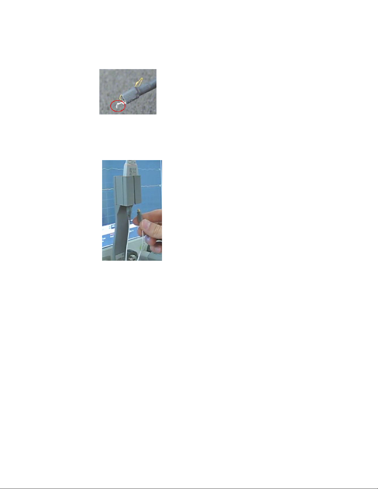
4 Calibration / Deskew Procedure
Figure 78 Forming the Probe Head’s Tip
f Connect the probe head’s two lead cables to the probe amplifier as shown in
Figure 79.
Figure 79 Connect the Head to the Probe
g Position the probe head wires (if you are using the ZIF or Solder-in probe
heads) so they curl towards the scope as shown in Figure 80.
90 InfiniiMax III+ Series Probes User’s Guide
Page 91
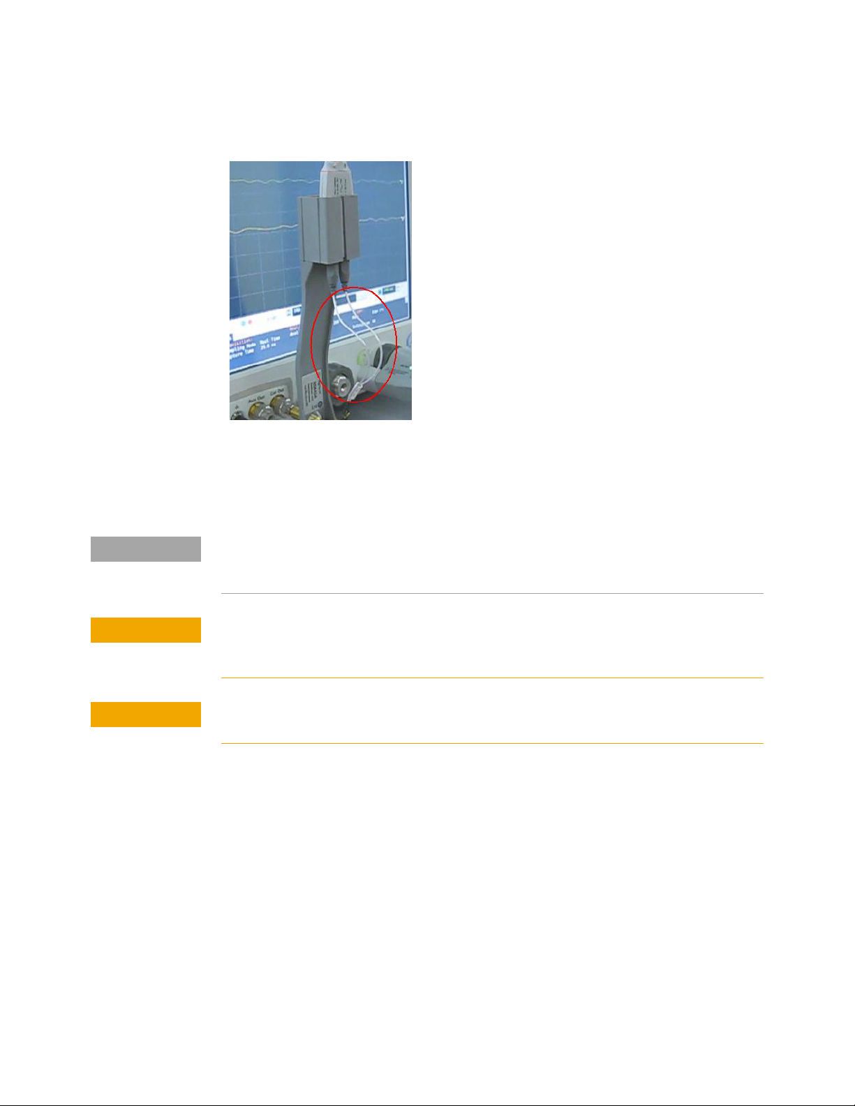
Calibration / Deskew Procedure 4
NOTE
CAUTION
CAUTION
Figure 80 Positioning the Probe Head Wires
h While pressing down on the N5443A fixture’s spring-loaded clamps, insert
the probe wires beneath the clamps. The N5443A’s clamps, ground, and
signal path are identified in Figure 81.
To check that the wires are connected correctly, press the oscilloscope’s autoscale button and
confirm that a stable step on screen. You will need to re-open the Probe Calibration dialog
box).
When connecting the probe head to the fixture, do not press down with much force or
you could snap off the fixture from the Cal Out or Aux Out connection. Light contact is
all that is needed for the calibration.
Never solder a probe tip to the thickfilm gold. The gold will immediately dissolve into
the solder and disappear.
InfiniiMax III+ Series Probes User’s Guide 91
Page 92
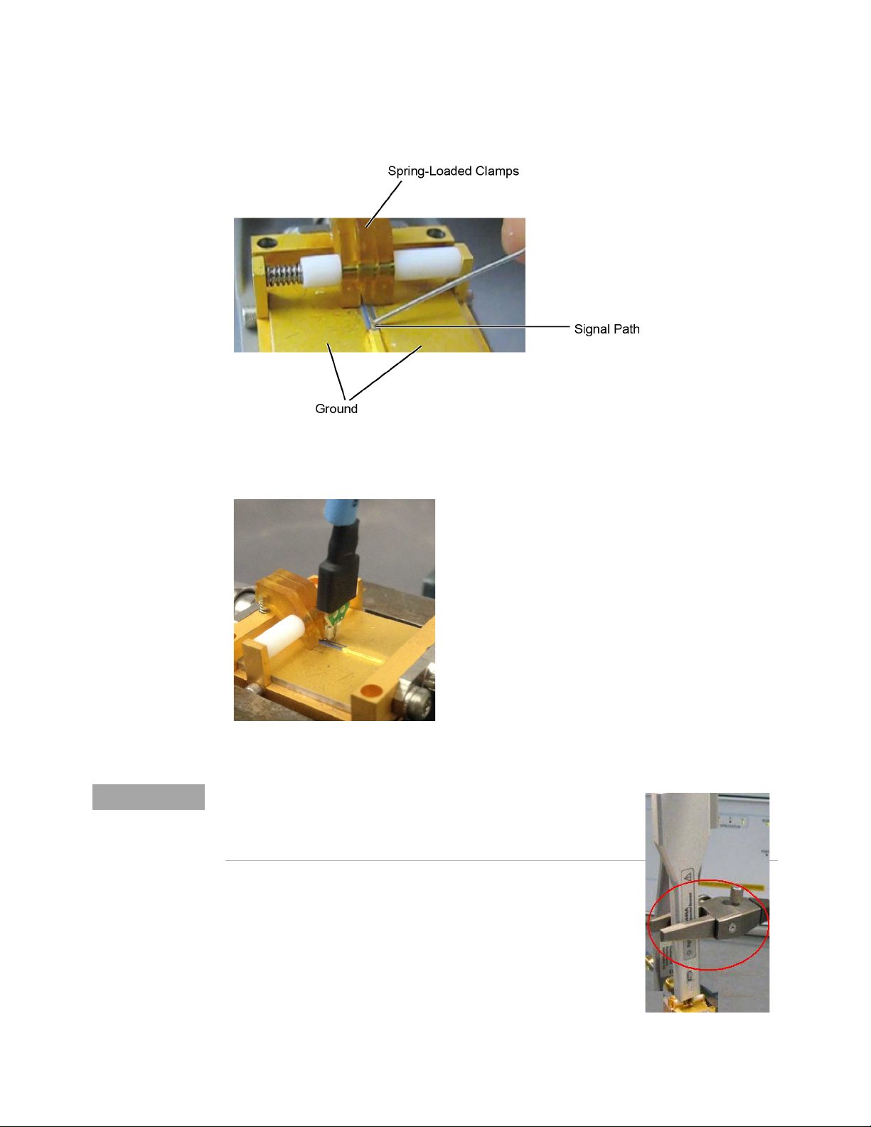
4 Calibration / Deskew Procedure
NOTE
Figure 81 Closeup of Fixture’s Signal Path, Ground, and Clamps
Figure 82 Clamping the Probe Head’s Leads
If you are using the browser probe head, it is recommended that you
use the N2787A 3D Probe Positioner to hold the browser in place as
shown here. The browser uses spring-loaded tips so you do not need
much force to get a solid contact.
92 InfiniiMax III+ Series Probes User’s Guide
Page 93

Calibration / Deskew Procedure 4
In the Probe Calibration dialog box, start the calibration.
5
6 When the calibration has completed, perform the skew calibration.
InfiniiMax III+ Series Probes User’s Guide 93
Page 94

4 Calibration / Deskew Procedure
94 InfiniiMax III+ Series Probes User’s Guide
Page 95

Keysight InfiniiMax III+ Series Probes
NOTE
User’s Guide
5 Specifications and
Characteristics
InfiniiMax III+ Warranted Specifications 96
N2830A/1A/2A and N7000/1/2/3A Probe Amplifiers Characteristics 97
N7000A/1A/2A InfiniiMax III+ Probe Heads Characteristics 99
N2830/1/2A InfiniiMax III+ Probe Heads Characteristics 100
Environmental 102
Safety and Regulatory Information 103
Probe Dimensions 104
Probe Heads Dimensions 105
All entries included in this chapter are characteristics unless otherwise
noted. These are the typical performance values of the InfiniiMax probes
using the InfiniiMax III+ probe amplifiers and each different probe head
except otherwise specified.
Bandwidth and DC input resistance (R
specifications.
and R
se
) are the only
diff
95
Page 96

5 Specifications and Characteristics
InfiniiMax III+ Warranted Specifications
Table 18 Warranted Specifications
Probe Head Probe Amplifier Bandwidth DC Input Resistance
N2836A / MX0109A 450 W solder-in
probe head vertical orientation with
no ground wires
Differential mode N7003A 20
GHz probe amp
20 GHz R
=100 kW ± 2%,
diff
R
=50 kW ± 2%
se
96 InfiniiMax III+ Series Probes User’s Guide
Page 97

Specifications and Characteristics 5
P
max
rms
VinV
term
–()
()
2
55
------------------------------=
N2830A/1A/2A and N7000/1/2/3A Probe Amplifiers Characteristics
The characteristics listed in Table 19 are mainly determined by the probe amplifier.
Table 19 N2830A/1A/2A and N7000/1/2/3A InfiniiMax III+ Probe Amplifier Characteristics
(Sheet 1 of 2)
N2830A/1A/2A and N7000/1/2/3AInfiniiMax III+ Probe Amplifiers
Feature
With 450 W Probe Heads
(N5439A, N5445A, N5441A,
With N5444A 2.92 mm / 3.5
mm / SMA Probe Head
N2838A, N2836A, MX0109A,
N2848A)
DC Input Resistance R
= 50 kW ± 2% each input to
se
55W to V
term
ground
R
= 100 kW ± 2%
diff
R
= 25 kW ± 2%
cm
Input Resistance ( >10 KHz) R
= 500W ± 2% each input to
se
50W to 0.901 * V
term
ground
R
= 1 kW
diff
R
= 250W
cm
Input Voltage Range
(Differential or Single
Ended)
2.5 Vpp or ±1.25 V at 5:1
attenuation
5.0 Vpp or ± 2.50 V at 10:1
attenuation
2.5 Vpp or ± 1.25 V at 5:1
attenuation
5.0 Vpp or ± 2.50 V at 10:1
attenuation without violating
max input power
Maximum Input Power N/A 125 mW calculated with the
following equation for each
input:
Input Common Mode Range ± 7 V
± 1.25 V > 100 Hz at 5:1
attenuation
± 2.5 V > 100 Hz at 10:1
attenuation
to 100 Hz
DC
± 6 V
to 100 Hz
DC
± 1.25 V > 100 Hz at 5:1
attenuation
± 2.5 V > 100 Hz at 10:1
attenuation without violating
max input power
DC Attenuation Ratio 5:1 or 10:1 Automatically selected
based on volts/division (all modes)
5:1 or 10:1 Automatically
selected based on
volts/division (all modes)
Offset Range (for probing a
single-ended signal)
InfiniiMax III+ Series Probes User’s Guide 97
±16V ±6V without violating
maximum input power
Page 98

5 Specifications and Characteristics
Table 19 N2830A/1A/2A and N7000/1/2/3A InfiniiMax III+ Probe Amplifier Characteristics
(Sheet 2 of 2)
N2830A/1A/2A and N7000/1/2/3AInfiniiMax III+ Probe Amplifiers
Feature
Input Referred Noise
Spectral Density
Input Referred Noise
Example
4.5 mV
with >= 18 GHz probe head and 13
GHz probe amp
Maximum Input Voltage 18 V
With 450 W Probe Heads
(N5439A, N5445A, N5441A,
N2838A, N2836A, MX0109A,
N2848A)
Diff 5:1 atten 33.5 nV/rt (Hz)
Diff 10:1 atten 53.9 nV/rt (Hz)
SE A or B 5:1 atten 27.8 nV/rt (Hz)
SE A or B 10:1 atten 47.7 nV/rt (Hz)
CM 5:1 atten 21.8 nV/rt (Hz)
CM 10:1 atten 38.4 nV/rt (Hz)
in diff mode 5:1 atten
rms
CAT 1 8 V
peak
With N5444A 2.92 mm / 3.5
mm / SMA Probe Head
4.5 mV
in diff mode 5:1
rms
atten with 30 GHz N5444A
probe head and 13 GHz probe
amp
without violating
peak
maximum input power
98 InfiniiMax III+ Series Probes User’s Guide
Page 99

Specifications and Characteristics 5
N7000A/1A/2A InfiniiMax III+ Probe Heads Characteristics
The characteristics listed in Table 20 are for the N7003A 20 GHz probe amplifier
using different probe heads. These characteristics are mainly determined by the
probe heads.
Performance listed in this table is with the highest bandwidth probe amp (N7003A
20 GHz) model in N700XA InfiniiMax III+ probe family. Performance with lower
bandwidth amps (N7000A/1A/2A) is the lower of the following:
•Amplifier BW
• 0.434/Amplifier BW
• .308/Amplifier BW
• bandwidth measured with the highest bandwidth amplifier (N7003A) in the
family.
Table 20 Characteristics for Probe Heads Using N7003A Probe Amplifier
Probe Head Input Capacitance Mode Bandwidth
C
diff
N5439A ZIF N5440A
450W ZIF tip
N2838A
450W ZIF tip
N5445A 450W Browser 35 fF 50 fF 20 GHz 21.7 ps 15.4 ps
N5441A 450W Solder-In 77 fF 105 fF 20 GHz 21.7 ps 15.4 ps
MX0109A 450W Solder-In Head
(Vertically orientation with no ground
wires) Or
(Flat orientation with minimum
length ground wires)
N2836A 450W Solder-In Head
(Vertically orientation with no ground
wires) Or
(Flat orientation with minimum
length ground wires)
N2848A
QuickTip
(with ground
wires connected)
N2849A 450W
QuickTip
32 fF 44 fF Differential 20 GHz 21.7 ps 15.4 ps
95 fF 130 fF 20 GHz 21.7 ps 15.4 ps
108 fF 140 fF 20 GHz 21.7 ps 15.4 ps
108 fF 140 fF 20 GHz 21.7 ps 15.4 ps
200 fF 340 fF 20 GHz 21.7 ps 15.4 ps
C
se
(–3 dB)
10 – 90%
Tra nsit ion
Time
20 – 80%
Transi tio n
Time
N5444A 2.92 /3.5 mm /SMA N/A N/A 20 GHz 21.7 ps 15.4 ps
InfiniiMax III+ Series Probes User’s Guide 99
Page 100

5 Specifications and Characteristics
N2830/1/2A InfiniiMax III+ Probe Heads Characteristics
The characteristics listed in the Table 21 are for the N2832A InfiniiMax III+ probe
amplifier using different probe heads. These characteristics are mainly determined
by the probe head.
Performance listed in this table is with the highest bandwidth probe amp
(N2832A) model in N283XA InfiniiMax III+ probe family. Performance with lower
bandwidth amps (N2830A/1A) is the lower of the following:
•Amplifier BW
• 0.434/Amplifier BW
• .308/Amplifier BW
• bandwidth measured with the highest bandwidth amplifier (N2832A) in the
family.
Table 21 Characteristics for Probe Heads Using N2832A Amplifier (Sheet 1 of 2)
Probe Head Tip Input Capacitance Mode Bandwidth
C
diff
N5439A ZIF N5440A
450W ZIF
N2838A
450W ZIF
N5447A
200W ZIF
N5445A 450W Browser 35 fF 50 fF Differential:
N5441A 450W Solder-In 77 fF 105 fF Differential:
MX0109A 450W Solder-In Head
(Vertically orientation with no ground
wires) Or
(Flat orientation with minimum
length ground wires)
32 fF 44 fF Differential:
95 fF 130 fF Differential:
Not compatible with N2830/1/2A probes.
108 fF 140 fF Differential:
C
se
Single Ended:
Common:
Single Ended:
Common:
Single Ended:
Common:
Single Ended:
Common:
Single Ended:
Common:
(–3 dB)
13 GHz
—
—
13 GHz
—
—
13 GHz
—
—
13 GHz
—
—
13 GHz
—
—
10 – 90%
Tra nsit ion
Time
33.4 ps
—
—
33.4 ps
—
—
33.4 ps
—
—
33.4 ps
—
—
33.4 ps
—
—
20 – 80%
Tra nsit ion
Time
23.7 ps
—
—
23.7 ps
—
—
23.7 ps
—
—
23.7 ps
—
—
23.7 ps
—
—
100 InfiniiMax III+ Series Probes User’s Guide
 Loading...