

Keysight N5445A InfiniiMax III, N2848A InfiniiMax III+, N5439A InfiniiMax III, N2836A InfiniiMax III, N5441A InfiniiMax III User Manual
...Page 1
Keysight N2800A Series
Differential InfiniiMax III Probes
User’s Guide
Page 2

Notices
CAUTION
WARNING
© Keysight Technologies, 2016, 2017
No part of this manual may be reproduced in
any form or by any means (including electronic storage and retrieval or translation
into a foreign language) without prior agreement and written consent from Keysight
Technologies, Inc. as governed by United
States and international copyright laws.
Manual Part Number
N2800-97020
Edition
May 2017
Published in USA
Published by:
Keysight Technologies, Inc.
1400 Fountaingrove Parkway
Santa Rosa, CA 95403 USA
Warranty
The material contained in this document is provided “as is,” and is subject
to being changed, without notice, in
future editions. Further, to the maximum extent permitted by applicable
law, Keysight disclaims all warranties,
either express or implied, with regard
to this manual and any information
contained herein, including but not
limited to the implied warranties of
merchantability and fitness for a particular purpose. Keysight shall not be
liable for errors or for incidental or
consequential damages in connection
with the furnishing, use, or performance of this document or of any information contained herein. Should
Keysight and the user have a separate
written agreement with warranty terms
covering the material in this document
that conflict with these terms, the warranty terms in the separate agreement
shall control.
U.S. Government Rights
The Software is "commercial computer software,"
as defined by Federal Acquisition Regulation
("FAR") 2.101. Pursuant to FAR 12.212 and
27.405-3 and Department of Defense FAR Supplement ("DFARS") 227.7202, the U.S. government acquires commercial computer software
under the same terms by which the software is
customarily provided to the public. Accordingly,
Keysight provides the Software to U.S. government customers under its standard commercial
license, which is embodied in its End User License
Agreement (EULA), a copy of which can be found
at
http://www.keysight.com/find/sweula. The
license set forth in the EULA represents the exclusive authority by which the U.S. government may
use, modify, distribute, or disclose the Software.
The EULA and the license set forth therein, does
not require or permit, among other things, that
Keysight: (1) Furnish technical information related
to commercial computer software or commercial
computer software documentation that is not customarily provided to the public; or (2) Relinquish
to, or otherwise provide, the government rights in
excess of these rights customarily provided to the
public to use, modify, reproduce, release, perform, display, or disclose commercial computer
software or commercial computer software documentation. No additional government requirements beyond those set forth in the EULA shall
apply, except to the extent that those terms,
rights, or licenses are explicitly required from all
providers of commercial computer software pursuant to the FAR and the DFARS and are set forth
specifically in writing elsewhere in the EULA. Keysight shall be under no obligation to update,
revise or otherwise modify the Software. With
respect to any technical data as defined by FAR
2.101, pursuant to FAR 12.211 and 27.404.2 and
DFARS 227.7102, the U.S. government acquires
no greater than Limited Rights as defined in FAR
27.401 or DFAR 227.7103-5 (c), as applicable in
any technical data. 52.227-14 (June 1987) or
DFAR 252.227-7015 (b)(2) (November 1995), as
applicable in any technical data.
Safety Notices
A CAUTION notice denotes a hazard.
It calls attention to an operating
procedure, practice, or the like that,
if not correctly performed or
adhered to, could result in damage
to the product or loss of important
data. Do not proceed beyond a CAU-
TION notice until the indicated conditions are fully understood and
met.
A WARNING notice denotes a hazard. It calls attention to an operating procedure, practice, or the like
that, if not correctly performed or
adhered to, could result in personal
injury or death. Do not proceed
beyond a WARNING notice until the
indicated conditions are fully
understood and met.
Technology Licenses
The hardware and/or software described in
this document are furnished under a license
and may be used or copied only in accordance with the terms of such license.
Page 3

Contents
1 Using InfiniiMax III Series Probes
2 InfiniiMax III Probe Heads
3 Maintaining Probe Heads
InfiniiMax III Probe Amplifiers 6
InfiniiMax III and III+ Probing System Family Diagram 9
Proper Handling Techniques 11
N5477A Sampling Scope Adapter 16
Cautions 17
N5445A InfiniiMax III Differential Browser Probe Head 20
N2848A InfiniiMax III+ QuickTip InfiniiMode Probe Head 25
N5439A InfiniiMax III ZIF Probe Head 29
N2836A InfiniiMax III Solder-in Probe Head 35
N5441A InfiniiMax III Solder-in Probe Head 39
N5444A InfiniiMax III 2.92 mm / 3.5 mm / SMA Probe Head 42
N2835A InfiniiMax III Differential Connectivity Kit and Accessories 44
Strain Relieving the Probe Heads 46
Replacing Axial Resistor Tips 50
Replacing N5441A Probe Head Wires 53
4 Performance Specifications / Characteristics
Specifications and Characteristics 58
InfiniiMax III Probe Heads Dimensions 65
5 Calibration / Deskew Procedure
Procedure 70
6 Performance Verification
Bandwidth Performance Verification 78
DC Input Resistance Performance Verification 96
Performance Test Record 99
7Performance Plots
N2836A 26 GHz Solder-In Head (with N2803A) 103
N2838A/N5439A 25 GHz PCB ZIF Tip/Head (with N2803A) 106
N5440A/N5439A 28 GHz Ceramic ZIF Tip/Head (with N2803A) 109
N5447A/N5439A 28 GHz Ceramic High-Sensitivity ZIF Tip/Head (with N2803A) 112
N5441A 16 GHz Solder-In Head (with N2803A) 115
3
Page 4

N5444A 30 GHz SMA 2.92 mm Head (with N2803A) 118
N5445A 30 GHz Browser Head, 1 mm span (with N2803A) 121
N5445A 30 GHz Browser Head, 2 mm span (with N2803A) 124
N5445A 30 GHz Browser Head, 3 mm span (with N2803A) 127
8SPICE Models
SPICE Models for N5440/1/4/5/7A Probe Heads 130
SPICE Models for N2838A and N2836A Probe Head 136
Simplified InfiniiMax III Schematic 139
4 InfiniiMax III Series Probes
Page 5

Keysight InfiniiMax III Series Probes
CAUTION
User’s Guide
1 Using InfiniiMax III Series
Probes
InfiniiMax III Probe Amplifiers 6
InfiniiMax III and III+ Probing System Family Diagram 9
Proper Handling Techniques 11
N5477A Sampling Scope Adapter 16
Cautions 17
This chapter contains documentation on using the InfiniiMax III probing system.
The InfiniiMax III probing system offers you the highest performance available for
measuring differential and single-ended signals, with flexible connectivity solutions for
today’s high-density ICs and circuit boards. Four different InfiniiMax III probe amplifiers
ranging from 16 GHz to 30 GHz are available for matching your probing solution to your
performance and budget requirements. A proprietary 200 GHz fT InP (indium phosphide)
IC process with backside ground vias and novel thick film technology is utilized to
accommodate your highest performance needs.
The family diagram for the InfiniiMax III probing system is shown in “InfiniiMax III and III+
Probing System Family Diagram" on page 9. This system is designed to give you the
maximum flexibility in matching your probe to your setup. The following pages will discuss
each of the adapters, probe amplifiers, and probe heads in detail.
Refer to “Proper Handling Techniques" on page 11 before connecting any probe to the
oscilloscope.
5
Page 6
1 Using InfiniiMax III Series Probes
InfiniiMax III Probe Amplifiers
There are four InfiniiMax III amplifier models:
• N2800A 16 GHz Probe Amplifier
• N2801A 20 GHz Probe Amplifier
• N2802A 25 GHz Probe Amplifier
• N2803A 30 GHz Probe Amplifier
Each probe amplifier is pre-loaded with its specific measured S-parameters. When used
with the Infiniium 90000 X-series, the oscilloscope downloads these parameters and
automatically corrects the response of the unique probe system.
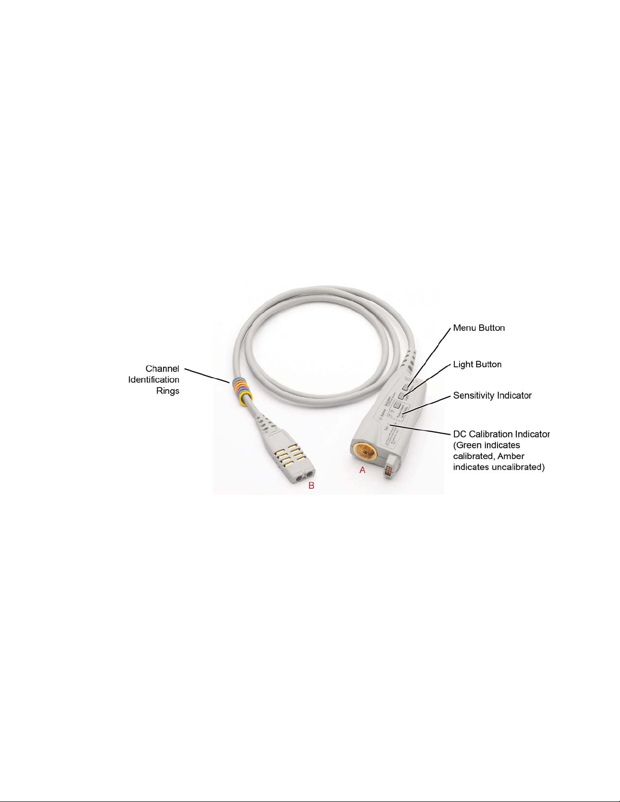
Figure 1 InfiniiMax III Probe Amplifier
Menu Button
Press this button to bring up the Probe dialog box in the oscilloscope GUI.
Light Button
Press this button to turn the LED headlights on the browser probe head on/off. Pressing
and holding this button will ramp the intensity of the LED headlights. You may want to
adjust the brightness to accommodate different lighting or glare conditions.
6 InfiniiMax III Series Probes User’s Guide
Page 7

Sensitivity Indicator
CAUTION
CAUTION
CAUTION
If you are using the ZIF probe head, the sensitivity indicator tells you which ZIF tip is
connected to the probe head. If the N5447A ceramic high sensitivity ZIF tip is connected
then the “Hi” sensitivity LED will be illuminated. If the N5440A ceramic ZIF tip is connected
then the “Normal” sensitivity LED will be illuminated. This will assist you in ensuring that
the correct ZIF tip is selected in the oscilloscope GUI’s probe dialog box.
If you select the wrong pairing of ZIF probe head and ZIF probe tip in the oscilloscope GUI’s
probe menu, your waveforms will look incorrect.
DC Calibration Indicator
Indicates if the particular combination of probe amplifier, probe head, and oscilloscope
channel input is calibrated. Any time you use a new probe head type, a new probe
amplifier, or a different channel on the oscilloscope, the DC Cal indicator turns amber,
indicating that a DC calibration is required. After performing a calibration as described in
Chapter 5, “Calibration / Deskew Procedure”, the DC Cal indicator turns green.
Using InfiniiMax III Series Probes 1
Channel Identification Rings
Use the channel-identification rings to match each probe to the color of the oscilloscope’s
input channel to which it is connected. This enables you to quickly know which probe is
connected to each channel without having to trace cables back to the oscilloscope inputs.
Channel Connection
Refer to “Proper Handling Techniques" on page 11 before connecting any probe to the
oscilloscope.
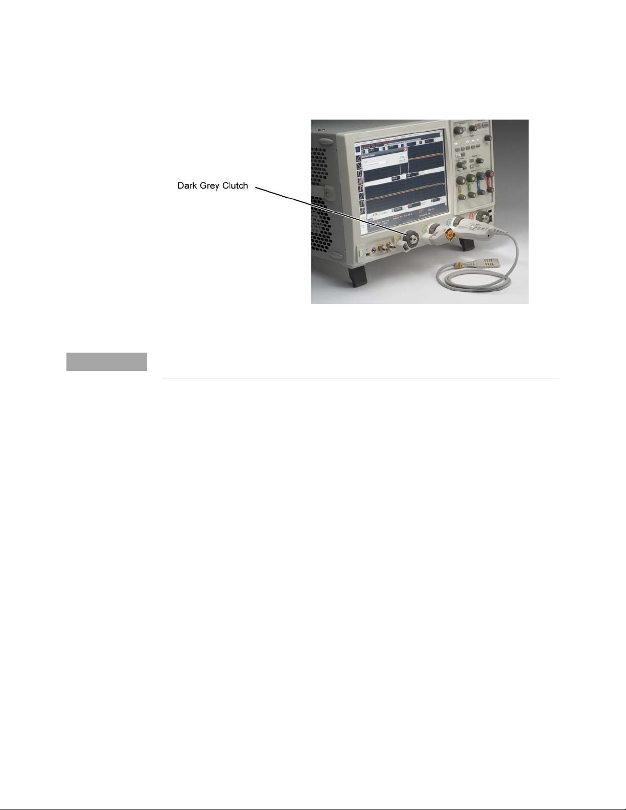
The connector labeled A in Figure 1 on page 6 plugs into one of the oscilloscope channel
inputs. If connecting it directly to an Infiniium 90000 X-series oscilloscope, plug it into the
channel and then turn the gray clutch/dial around the input (Figure 2 on page 8) until it
clicks. To disconnect the probe amplifier, loosen the clutch on the oscilloscope input and
disconnect the probe amplifier. If you are using an InfiniiMax III probe amplifier with
Keysight’s 86100D sampling oscilloscope, you will need to use the N5477A sampling
scope adapter.
The connector labeled B in Figure 1 on page 6 connects to one of the InfiniiMax III probe
heads.
InfiniiMax I and II probe heads are not compatible with the InfiniiMax III probe amplifiers and
vice versa.
InfiniiMax III Series Probes User’s Guide 7
Page 8
1 Using InfiniiMax III Series Probes
NOTE
Figure 2 Clutches on an Infiniium 90000 X-series oscilloscope
The clutches on the Infiniium 90000 X-series do not require a mechanical calibration. They will maintain
the same tolerance as the Keysight torque wrench (8 in lbs ±1 in lbs).
Probe Amplifier Bandwidth Upgrades
The InfiniiMax III probe amplifiers are upgradeable. When you order a probe bandwidth
upgrade, you receive a new probe with a new model number and new serial number. The
bandwidth upgrades are:
• N5446A-001 16 GHz to 20 GHz bandwidth upgrade
• N5446A-002 20 GHz to 25 GHz bandwidth upgrade
• N5446A-003 25 GHz to 30 GHz bandwidth upgrade
• N5446A-004 16 GHz to 25 GHz bandwidth upgrade
• N5446A-005 16 GHz to 30 GHz bandwidth upgrade
• N5446A-006 20 GHz to 30 GHz bandwidth upgrade
8 InfiniiMax III Series Probes User’s Guide
Page 9
Using InfiniiMax III Series Probes 1
InfiniiMax III and III+ Probing System Family Diagram
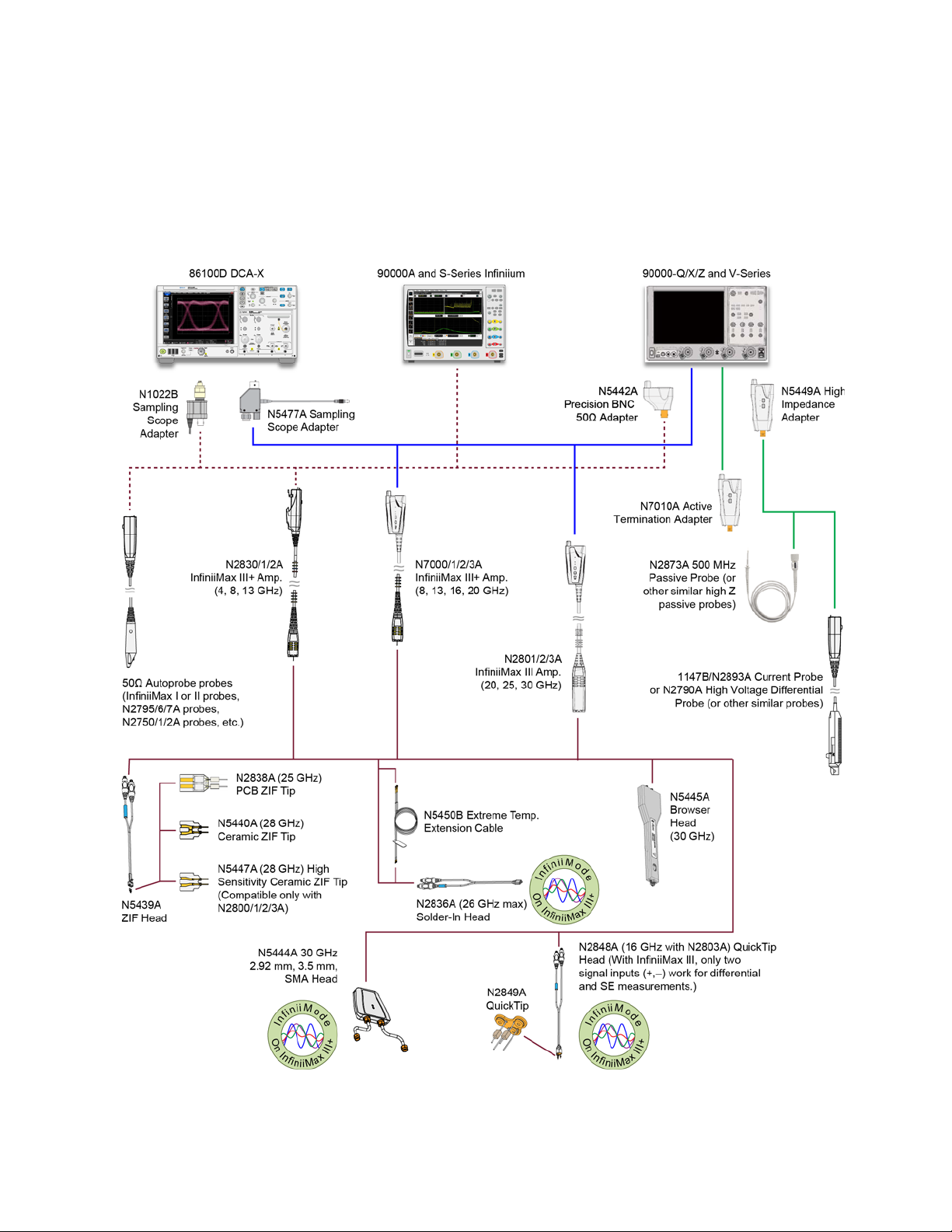
The following diagram shows the InfiniiMax III and InfiniiMax III+ probes and probe heads.
The diagram is not drawn to scale.
Figure 3 InfiniiMax III / III+ Probing System
InfiniiMax III Series Probes User’s Guide 9
Page 10
1 Using InfiniiMax III Series Probes
CAUTION
CAUTION
CAUTION
NOTE
For extreme temperature testing, use the N5450B InfiniiMax extreme temperature
extension cable with the N5441A solder-in head. The N5441A can withstand temperatures
from –55°C to +150°C for up to 250 test cycles.
None of the N2800/1/2/3A probe amplifiers can withstand the extreme temperatures (–55°C
to +150°C) that the N5450B can withstand. When using the N5450B extension cable, do not
subject the InfiniiMax III probe amplifier to extreme temperatures.
None of the other probe heads are designed for extreme temperature testing.
The N5449A includes one N2873A probe. The adapter is specifically tuned for the N2873A
probe. Similar probes (1 ΜΩ input) can be used. Other probes may not meet the
bandwidth specification.
When using the N5450B extension cable, do not subject the InfiniiMax III probe amplifier or
probe head (other than the N5441A solder-in probe head) to extreme temperatures.
N2849A QuickTips are also compatible with N2851A QuickTip Probe Heads, which are designed for
1130/1/2/4A InfiniiMax I and 1168/9A InfiniiMax II probes.
Use the N5443A Performance Verification (PV) accessory fixture to properly
position the probe for PV testing.
10 InfiniiMax III Series Probes User’s Guide
Page 11

Proper Handling Techniques
CAUTION
CAUTION
CAUTION
CAUTION
CAUTION
CAUTION
This guide will assist you in properly handling your InfiniiMax III N2800A-series probes to
prevent damage and maintain high performance. For more safe-handling information, go
to www.keysight.com/find/scope-demo, click on See Keysight's probes in action, and then
InfiniiMax III ESD Best Practices demo video listed under the Document Library tab.
Electrostatic discharge (ESD) can quickly and imperceptibly damage or destroy
high-performance probes, resulting in costly repairs. Always wear a wrist strap when handling
probe components.
Probes are sensitive devices and should be treated with care. Do not bend or kink the probe
amplifier cable. Do not drop heavy objects on the probe, drop the probe from large heights,
spill liquids on the probe, etc. Any of these examples can significantly degrade the
performance of the probe.
When storing the probe, it is best to coil the cable in a large radius and avoid a net twist in the
cable during the process. This can be done in a similar manner to how garden hoses or
extension cords are typically coiled.
Using InfiniiMax III Series Probes 1
InfiniiMax I and II probe heads cannot be used with InfiniiMax III probe amplifiers and
InfiniiMax III probe heads cannot be used with InfiniiMax I and II amplifiers.
Never allow the probe head to be connected to the probe amplifier, if the probe amplifier is not
connected to the oscilloscope channel.
Always disconnect an N5441A solder-in probe head from the probe amplifier before
unsoldering, moving to a new position, and re-soldering the head.
Before Connecting a Probe
InfiniiMax probes and accessories are ESD sensitive devices and should be treated with
care. Before using or handling the probe or accessories, always wear a grounded ESD wrist
strap and ensure that cables and probe heads are discharged before being connected.
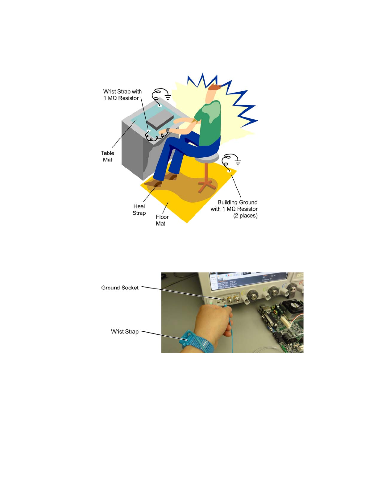
All work, including connecting probe amplifiers to the oscilloscope, should be performed
at a static-safe work station as shown in Figure 4 on page 12.
InfiniiMax III Series Probes User’s Guide 11
Page 12
1 Using InfiniiMax III Series Probes
Figure 4 Static-Safe Work Station
Many scopes including Keysight's 90000X series have a front-panel ground socket. You
can plug the wrist strap into the ground socket as seen in the following picture.
Figure 5 Wrist Strap Connected to Oscilloscope Ground Socket
The static-safe work station shown in Figure 4 uses two types of ESD protection:
• Conductive table-mat and wrist-strap combination.
• Conductive floor-mat and heel-strap combination.
Both types, when used together, provide a significant level of ESD protection. Of the two,
only the table-mat and wrist-strap combination provides adequate ESD protection when
used alone. To ensure user safety, the static-safe accessories must provide at least 1 MΩ
of isolation from ground. Purchase acceptable ESD accessories from your local supplier.
12 InfiniiMax III Series Probes User’s Guide
Page 13
WARNING
These techniques for a static-safe work station should not be used when working on
CAUTION
circuitry with a voltage potential greater than 500 volts.
Connecting a Probe to an Oscilloscope Channel
To protect against ESD damage, always use the following steps when connecting your
probe to the oscilloscope.
1 If the Device Under Test (DUT) is not grounded to the oscilloscope via the AC mains
ground, connect the DUT ground to the oscilloscope ground. An example of a device
having a floating ground would be a battery-powered DUT.
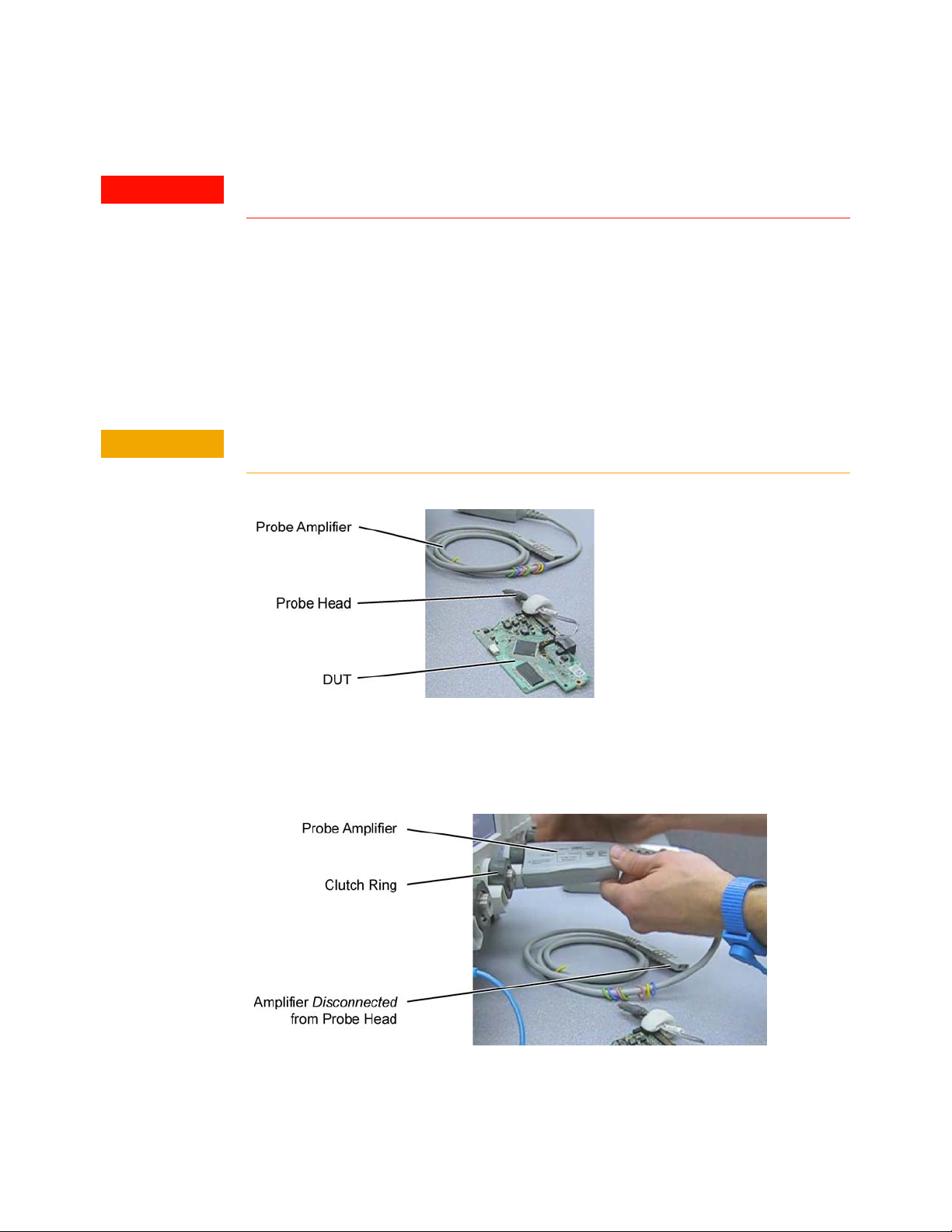
2 Attach the probe head to the DUT.
At this point, the N2800A-series probe amplifier must not be connected to the oscilloscope or
the probe head.
Using InfiniiMax III Series Probes 1
Figure 6 Probe Head Attached to DUT
3 Connect the probe amplifier to the oscilloscope while hand tightening the dark gray clutch
ring. The clutch ring limits the applied torque to 8 in-lb (±1 in-lb).
Figure 7 Probe Amplifier Connected to Oscilloscope
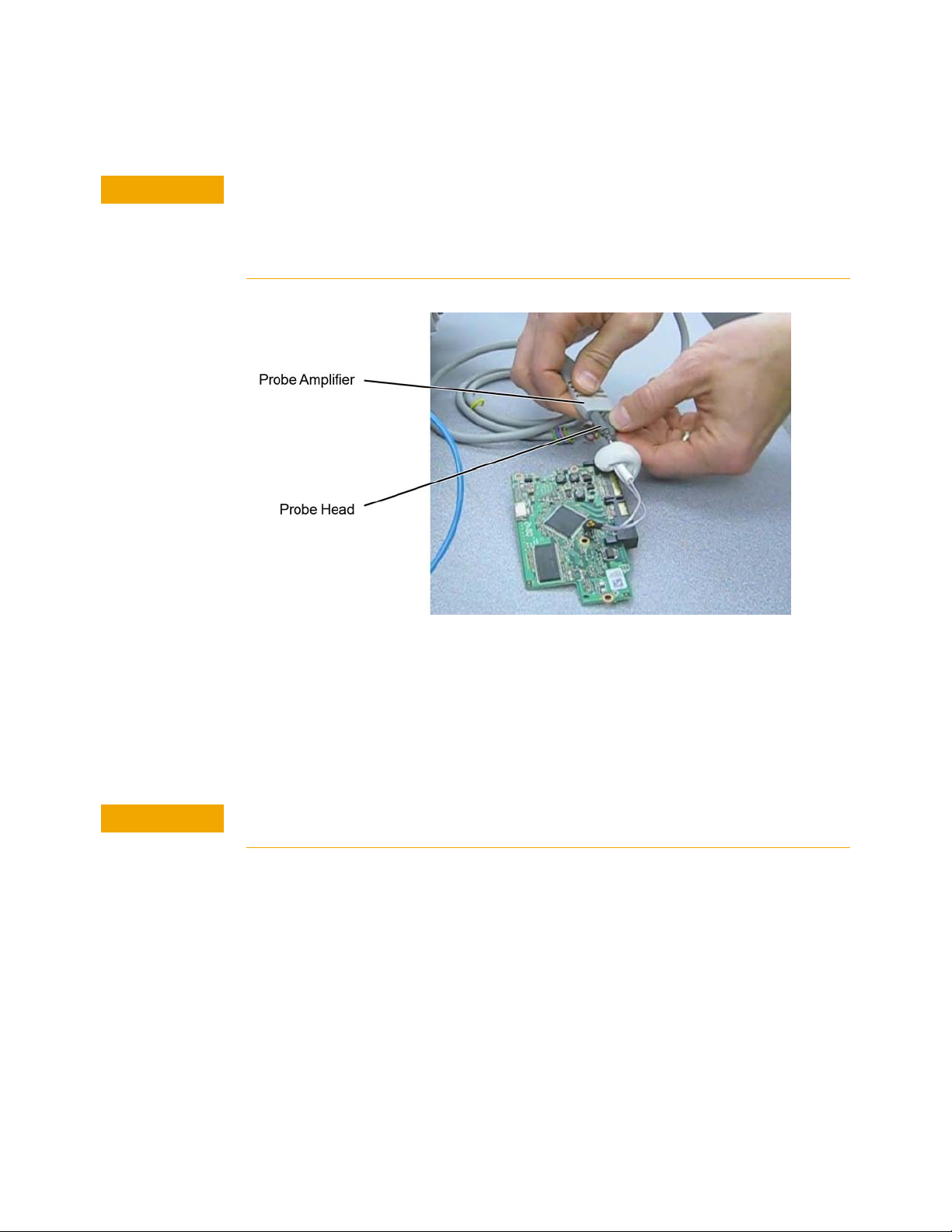
4 Connect the probe head to the probe amplifier.
InfiniiMax III Series Probes User’s Guide 13
Page 14
1 Using InfiniiMax III Series Probes
CAUTION
CAUTION
When connecting a probe head to a probe amplifier, push straight in. When disconnecting a
probe head from an amplifier, pull the probe head connectors straight out of the sockets.
Never bend the probe head in order to pry it loose from the amplifier. Also, do not wiggle the
probe head up and down or twist it to remove the connectors from the sockets. This can
damage the pins in the amplifier or the probe head itself.
Figure 8 Probe Head Connected to Probe Amplifier
Disconnecting a Probe from an Oscilloscope Channel
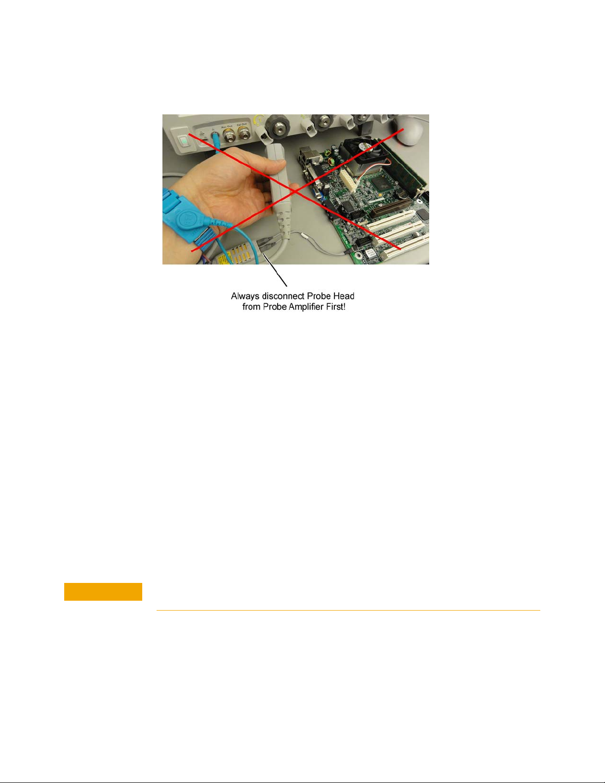
Always disconnect the probe head from the probe amplifier before:
• disconnecting the probe amplifier from the oscilloscope.
• switching the probe amplifier from one oscilloscope channel to another.
Never allow the probe head to be connected to the probe amplifier, if the probe amplifier is not
connected to the oscilloscope channel.
14 InfiniiMax III Series Probes User’s Guide
Page 15
Using InfiniiMax III Series Probes 1
CAUTION
Figure 9 Probe Improperly Disconnected from Oscilloscope while Probe Head is Connected
to the Probe Amplifier
Probing the DUT
When making your measurements, you’ll often need to probe different locations on the
DUT. You can safely move any of the following three probe heads without having to first
break the amplifier-to-head connection:
• N5445A differential browser head
• N5439A ZIF head
• N5444A 2.92 mm/3.5 mm/SMA head
The only exception is when the DUT is not grounded to the oscilloscope via the AC mains
ground. In this case, connect the DUT ground to the oscilloscope ground before moving
the probe. An example of a device having a floating ground would be a battery-powered
DUT.
When probing with an N5441A solder-in probe head, always disconnect the probe head
from the amplifier before moving the head to a new probing point. This is because some
soldering-iron tips can hold a charge which can damage the probe amplifier.
Always disconnect an N5441A solder-in probe head from the probe amplifier before
un-soldering, moving to a new position, and re-soldering the head.
InfiniiMax III Series Probes User’s Guide 15
Page 16
1 Using InfiniiMax III Series Probes
N5477A Sampling Scope Adapter
The N5477A Sampling Scope Adapter allows you to connect the InfiniiMax III probing
system to the Infiniium 86100D DCA-X sampling oscilloscope or other RF instruments.
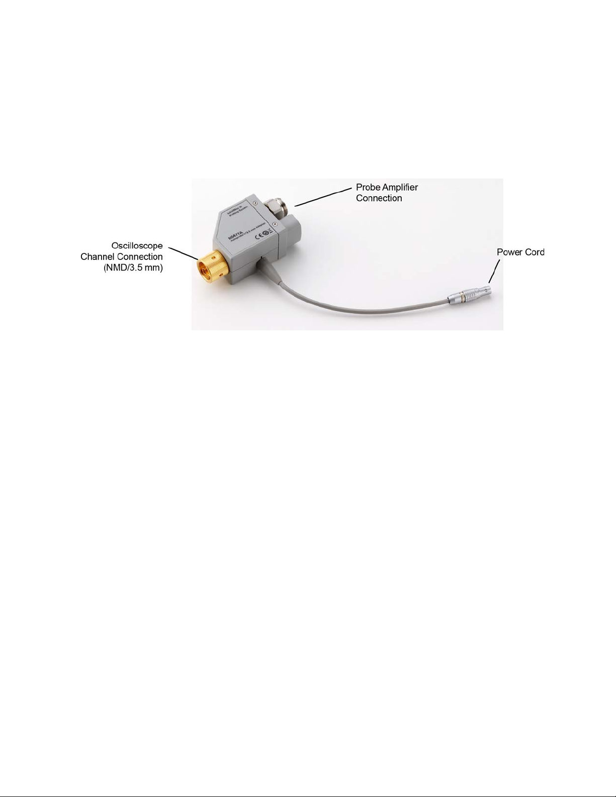
Figure 10 N5477A InfiniiMax III Sampling Scope Adapter
Connect the NMD/3.5 mm side of the adapter to one of the channel inputs on the
sampling oscilloscope. Then connect the power cord to either the probe power output on
the DCA-X 86100D wideband oscilloscope (if the module being used has this receptacle)
or to the 1143A power module. Finally, connect the other side of the adapter to the
InfiniiMax III probe amplifier.
Previously, the DCA-X wideband oscilloscope was limited to 13 GHz of probing, but with
the N5477A sampling oscilloscope adapter, the DCA-X can now probe up to 30 GHz.
The N5477A sampling oscilloscope adapter can also be used to connect the InfiniiMax III
probing system to generic 50 Ohm test equipment as long as the 1143A power supply and
5062-1247 NMD male-to-3.5mm female adapter are used. Both of these parts can be
ordered through Keysight Technologies.
16 InfiniiMax III Series Probes User’s Guide
Page 17

Cautions
CAUTION
CAUTION
CAUTION
CAUTION
CAUTION
CAUTION
Using InfiniiMax III Series Probes 1
In addition to the CAUTION notices below, also refer to the CAUTION notices listed in each
section of this book.
Electrostatic discharge (ESD) can quickly and imperceptibly damage or destroy
high-performance probes, resulting in costly repairs. Always wear a wrist strap when handling
probe components.
Probes are sensitive devices and should be treated with care. Do not bend or kink the probe
amplifier cable. Do not drop heavy objects on the probe, drop the probe from large heights,
spill liquids on the probe, etc. Any of these examples can significantly degrade the
performance of the probe.
Whenever you disconnect a probe head from an InfiniiMax amplifier, pull the probe head
connectors straight out of the sockets. When connecting a probe head to an amplifier, push
straight in also. Never bend the probe head in order to “pop” it loose from the amplifier. Also,
do not wiggle the probe head up and down or twist it to remove the connectors from the
sockets. This can damage the pins in the amplifier or the probe head itself.
When storing the probe, it is best to coil the cable in a large radius and avoid a net twist in the
cable during the process. This can be done in a similar manner to how garden hoses or
extension cords are typically coiled.
InfiniiMax I and II probe heads cannot be used with InfiniiMax III probe amplifiers and
InfiniiMax III probe heads cannot be used with InfiniiMax I and II amplifiers.
Always remove the probe head from the device under test (DUT) before disconnecting the
probe amp from the oscilloscope.
InfiniiMax III Series Probes User’s Guide 17
Page 18

1 Using InfiniiMax III Series Probes
18 InfiniiMax III Series Probes User’s Guide
Page 19

Keysight InfiniiMax III Series Probes
CAUTION
User’s Guide
2 InfiniiMax III Probe Heads
N5445A InfiniiMax III Differential Browser Probe Head 20
N2848A InfiniiMax III+ QuickTip InfiniiMode Probe Head 25
N5439A InfiniiMax III ZIF Probe Head 29
N2836A InfiniiMax III Solder-in Probe Head 35
N5441A InfiniiMax III Solder-in Probe Head 39
N5444A InfiniiMax III 2.92 mm / 3.5 mm / SMA Probe Head 42
N2835A InfiniiMax III Differential Connectivity Kit and Accessories 44
Strain Relieving the Probe Heads 46
This chapter documents the InfiniiMax III probe heads.
Refer to “Proper Handling Techniques" on page 11 before connecting any probe head to a
probe amplifier.
19
Page 20
2 InfiniiMax III Probe Heads
NOTE
N5445A InfiniiMax III Differential Browser Probe Head
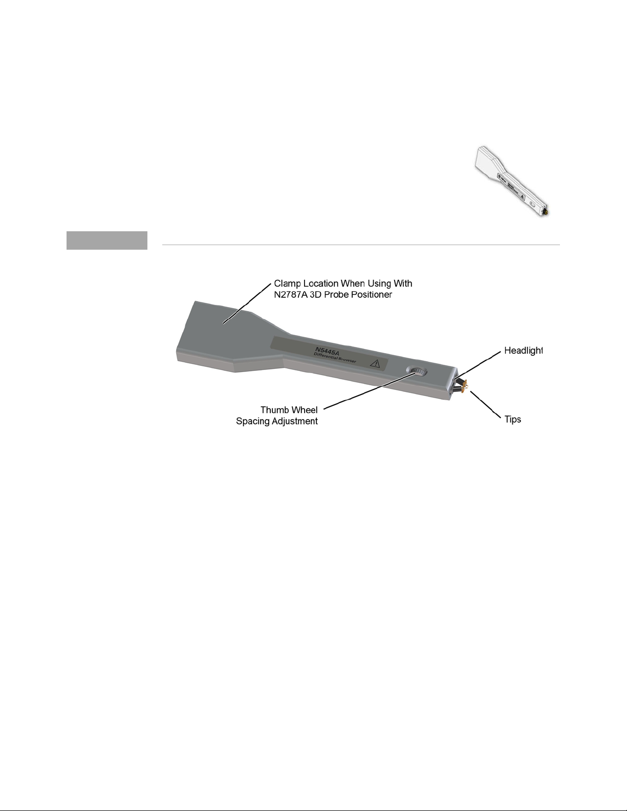
The N5445A browser head (30 GHz) is the best choice for the
general-purpose trouble shooting of differential signals with
spring-loaded tips and variable spacing from 20 mil to 125 mil (or
0.5 mm to 3.1 mm).
The span between the signal tips is easily adjusted with a thumb
wheel on the browser (see Figure 11).
For performance plots, refer to Chapter 7, “Performance Plots.
Figure 11 N5445A InfiniiMax III Differential Browser Head
Using the LED Headlights
A pair of LED headlights are integrated into the tip of the browser to illuminate the probing
area for better visibility. The headlights are controlled via the Light button on the InfiniiMax
III probe amplifier (see Figure 1 on page 6). Pressing this button turns the headlights on /
off while pressing the button and holding it down ramps the intensity of the headlights.
Adjusting the Tip Span
Turn the browser’s thumb wheel (see Figure 12) to adjust the tip spacing from 20 to
125 mil (0.5 mm to 3.1 mm). Do not force the adjustment near the end of its range.
20 InfiniiMax III Series Probes User’s Guide
Page 21
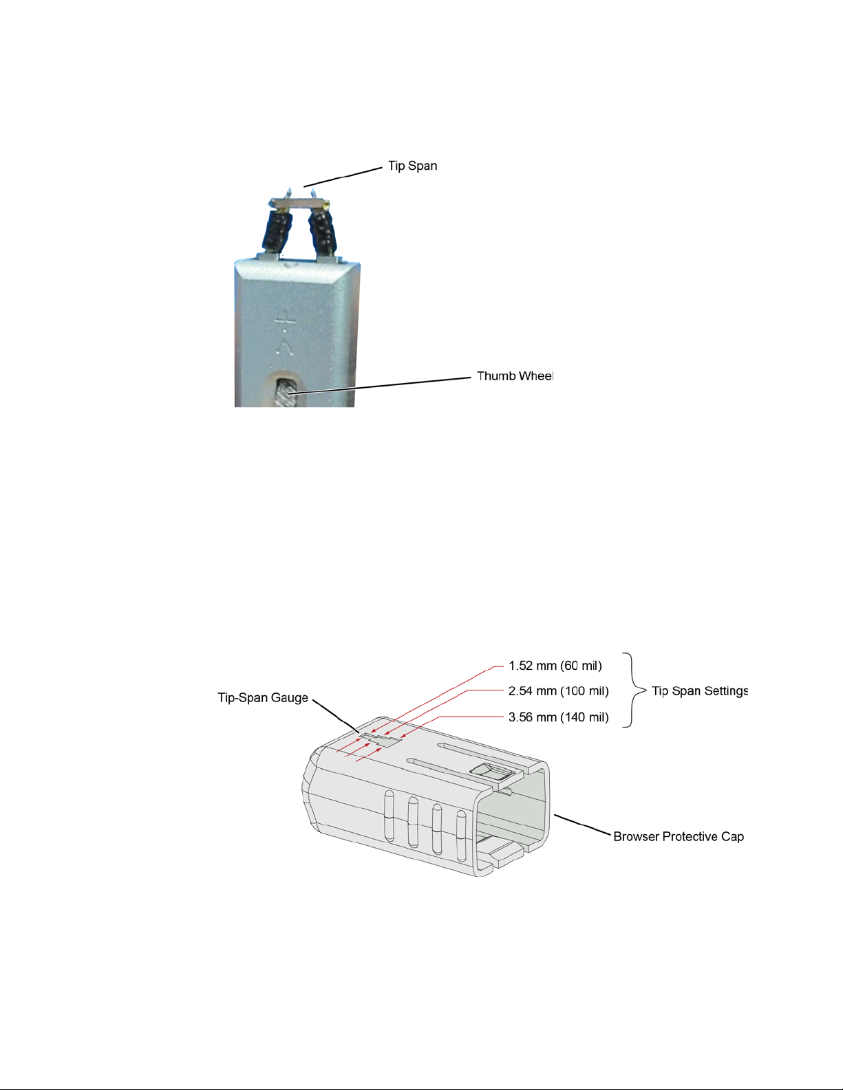
Figure 12 Adjusting the Tip Span
Tip-Span Entry for Probe Calibration
InfiniiMax III Probe Heads 2
When calibrating the probe, you will be prompted to enter the span setting on the
oscilloscope’s Probe Calibration dialog box. To determine the tip span, do the following
steps:
1 Adjust the browser’s tip span for your measurement.
2 Locate the tip-span gauge on the browser’s protective cap as shown in Figure 13.
3 Determine which of the three possible tip-span settings most closely matches the
browser’s tip span.
Figure 13 Tip Span Gauge on Browser Protective Cap
InfiniiMax III Series Probes User’s Guide 21
Page 22
2 InfiniiMax III Probe Heads
CAUTION
Mounting the Browser
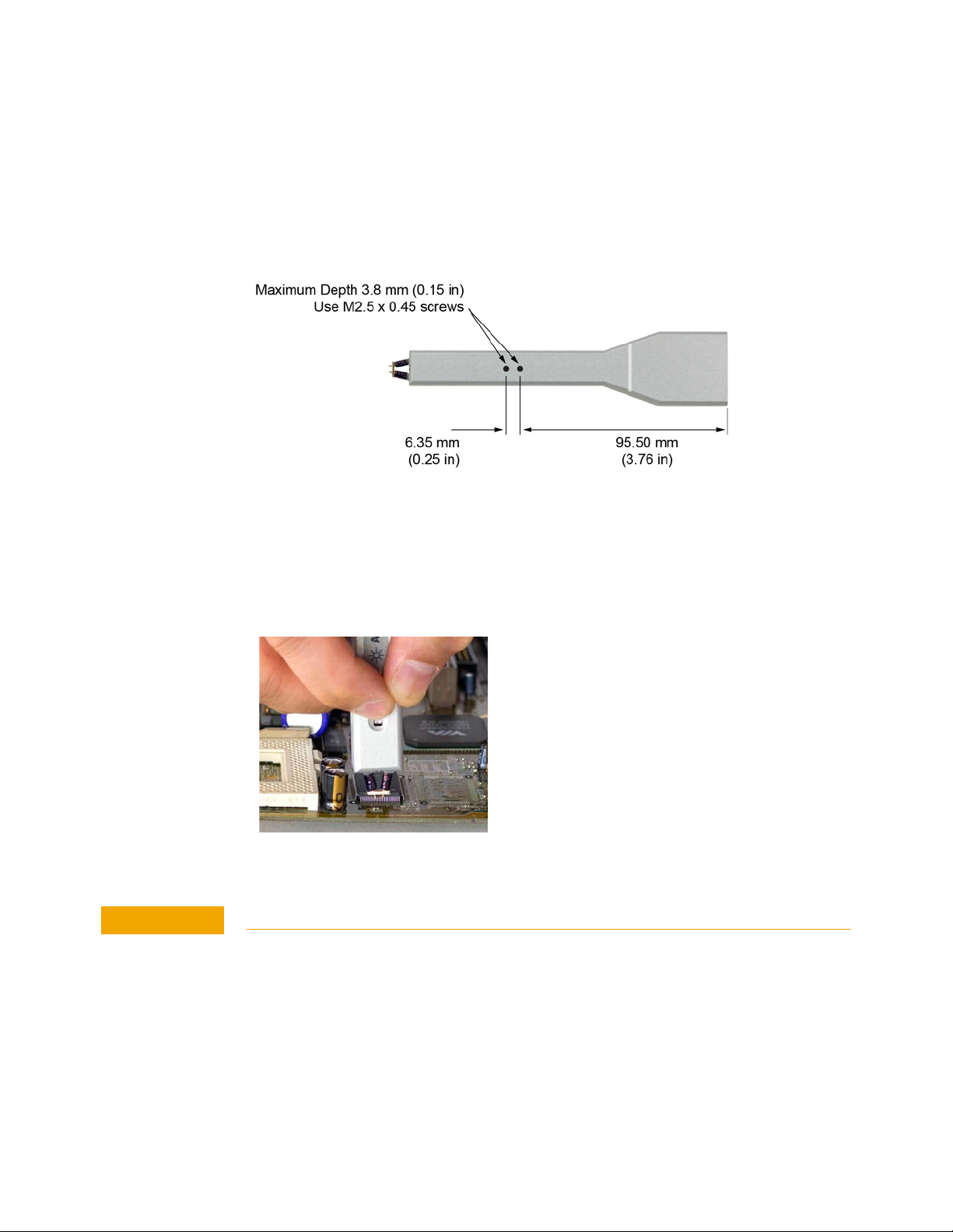
There are two holes on the back side of the browser. Use these holes to mount the browser
to a customer designed holder. Figure 14 below shows the dimensions of these mounting
holes.
Figure 14 Dimensions of Mounting Holes
Probe Along the Browser’s Axis
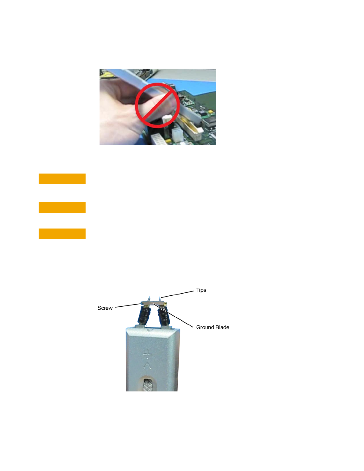
To prevent tip damage, probe along the browser’s axis as shown in Figure 15. Hold the
probe vertical and perpendicular to the circuit board.
Figure 15 Proper Probe Handling
To avoid damaging the browser’s tips, do not apply a side load to the browser.
22 InfiniiMax III Series Probes User’s Guide
Page 23
InfiniiMax III Probe Heads 2
CAUTION
CAUTION
CAUTION
Figure 16 Improper Probe Handling
Do not apply too much force when browsing. The weight of the probe in your hand should be
sufficient. The axial travel of the probe is about 15 mils (0.4 mm).
The browser’s protective cap should be kept on the browser at all times except when probing.
Always remove the browser from the device under test (DUT) before disconnecting the probe
amp from the oscilloscope.
Replaceable Parts
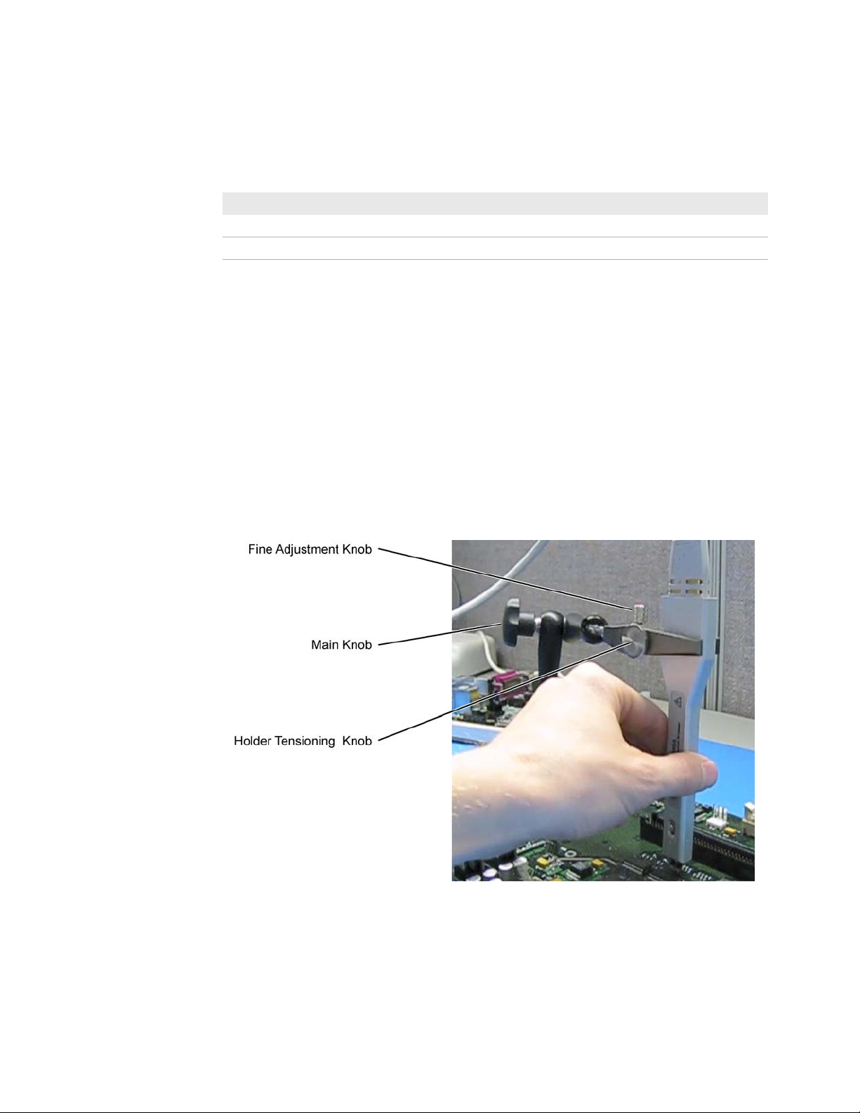
Figure 17 shows the replaceable parts for th N5445A.
Figure 17 Browser Tips and Ground Blade
InfiniiMax III Series Probes User’s Guide 23
Page 24
2 InfiniiMax III Probe Heads
Table 1 N5445A Replaceable Parts
Description Qty Part Number
Browser tips 4 N5476A
Ground Blade 1 N4855A
Ground Blade Screws 1 N4856A
N2787A 3D Probe Positioner
Using the N2787A 3D probe positioner with the N5445A browser probe head reduces the
chance of breaking the browser tips and ensures that the tips maintain solid contact. Use
the following steps to position the probe using the N2787A:
1 Lock the vertical compliance of the probe positioner.
2 Clamp the browser into the positioner, aligning the browser’s slot with the positioner’s
gripping pad.
3 While holding the browser, loosen the main knob and position the probe.
4 Use the browser’s own weight to depress the tips, and tighten the main knob to lock the
probe’s position.
Figure 18 Using the Browser with the N2787A 3D Probe Positioner
24 InfiniiMax III Series Probes User’s Guide
Page 25
InfiniiMax III Probe Heads 2
NOTE
N2848A InfiniiMax III+ QuickTip InfiniiMode Probe Head
The N2848A QuickTip probe head is used with an
N2849A QuickTip and together they provide the
following advantages:
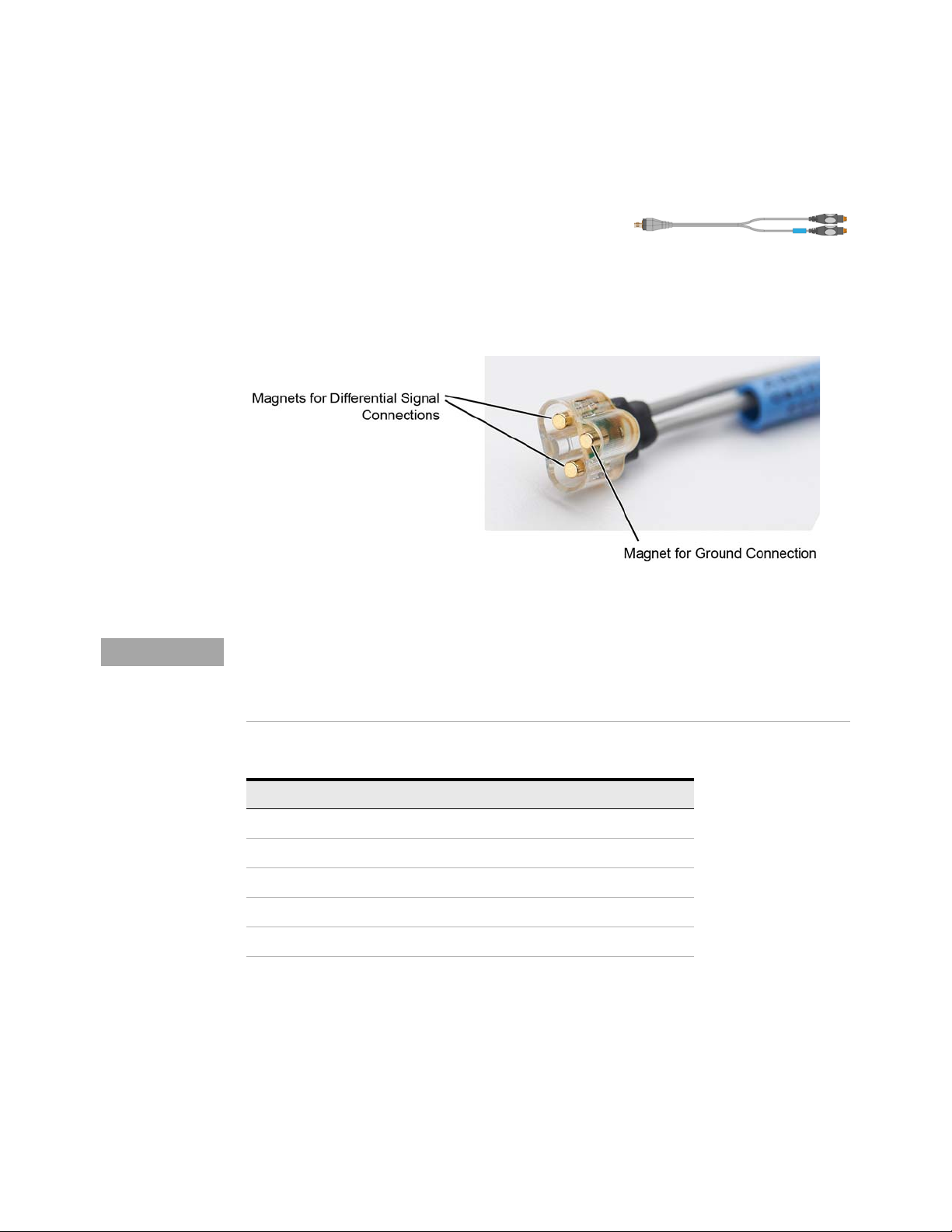
• Easy-to-make secure magnetic mechanical connection between probe head and
QuickTip as shown in Figure 19. No latch lever is used!
• Extreme temperature environments such as temperature chambers.
Figure 19 Magnet Connections in Probe Head
When used with N2830A-series probe amplifiers, the N2848A is InfiniiMode compatible.
InfiniiMode allows you to make differential, common mode, and single ended measurements
without having to re-solder the tip leads. InfiniiMode is not available when using with
N2800A-series probe amplifiers.
Table 2 N2848A with N2804A Probe Amplifier
Item Characteristic
Bandwidth 16 GHz
Input C (Differential) 340 fF
Input C (Single Ended 200 fF
Rise Time 27.1 ps (10 - 90%)
Fall Time 19.3 ps (20 - 80%)
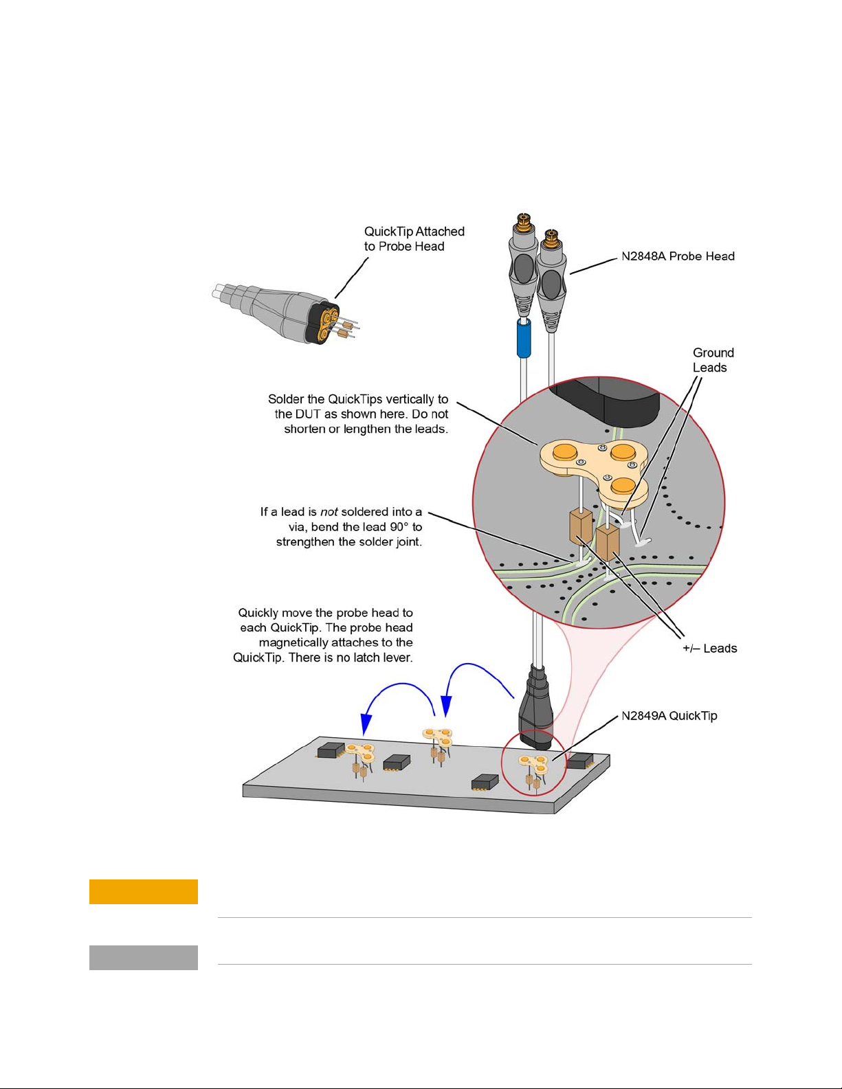
Permanently solder any number of N2849A QuickTips to your DUT as shown in Figure 20
on page 26. Because the probe head is magnetically connected (instead of mechanically
connected) to the QuickTip, you can effortlessly connect and disconnect to each QuickTip.
For best performance, position the QuickTip vertically on the DUT. The N2849A QuickTip
has two signal leads and two ground leads. The ground leads have minimal effect on your
differential measurements. However, if you are making only differential measurements you
InfiniiMax III Series Probes User’s Guide 25
Page 26
2 InfiniiMax III Probe Heads
CAUTION
NOTE
can optionally cut off the ground leads or fold them out of the way. Be aware that without
the ground leads, the mechanical stability of the QuickTip will be reduced and you will
need to stabilize the probe head.
Figure 20 Probing with the N2848A Probe Head and N2849A QuickTip
Do not replace or repair the N2849A QuickTip’s resistor or ground leads. Attempting to do so
will damage the ability of the tip to mate with the N2848A probe head.
The N2848A does not include any N2849A QuickTips. The N2849A must be ordered separately.
26 InfiniiMax III Series Probes User’s Guide
Page 27

N2849A QuickTips are also compatible with N2851A QuickTip InfiniiMode Probe Heads,
CAUTION
CAUTION
CAUTION
NOTE
NOTE
which are designed for 1130/1/2/4A InfiniiMax I and 1168/9A InfiniiMax II probes.
Connecting a QuickTip to the DUT
Use the following tips when soldering the QuickTips to your DUT:
• Orient the QuickTip vertically as shown in Figure 20 on page 26.
• Solder the four leads to vias or surfaces.
• When soldering to a via, always trim the lead close to the via’s underside.
• If a lead is to be soldered to a surface and not a via, make a stronger solder joint by
bending the end of the lead 90°. For signal leads, bend the wire approximately half way
between the resistor and the end of the wire. Bend the ground leads at about the same
distance.
Always mechanically strain-relieve the QuickTip head before using to protect both your probe
accessories and DUT from damage.
Be careful not to damage the tip wires when handling the QuickTips. Wires can be carefully
reshaped with tweezers or fingers if necessary.
InfiniiMax III Probe Heads 2
The QuickTips are very fragile. They must be manufactured in this way in order to meet the
high-performance, high bandwidth applications they are intended for. Be extremely careful
when handling.
Resistor and wire leads on the QuickTip are factory trimmed to the proper length for use. Adding wire
length to the tip of the mini-axial lead resistors or to the ground leads will degrade the performance of
the probe.
Soldering the ground wires is not required when making differential or single-ended (+ or – leads)
measurements.
InfiniiMax III Series Probes User’s Guide 27
Page 28

2 InfiniiMax III Probe Heads
Cleaning the Magnetic Connections
If the three magnetic connections in the head become dirty, clean the connections using
the following steps:
1 Use compressed air or a cloth to remove any loose dirt.
2 Gently rub a small piece of tack putty (supplied with the probe) against the magnetic
connections to clean off any remaining surface grime.
Figure 21 N2848A Head Before and After Cleaning
28 InfiniiMax III Series Probes User’s Guide
Page 29
InfiniiMax III Probe Heads 2
NOTE
NOTE
NOTE
N5439A InfiniiMax III ZIF Probe Head
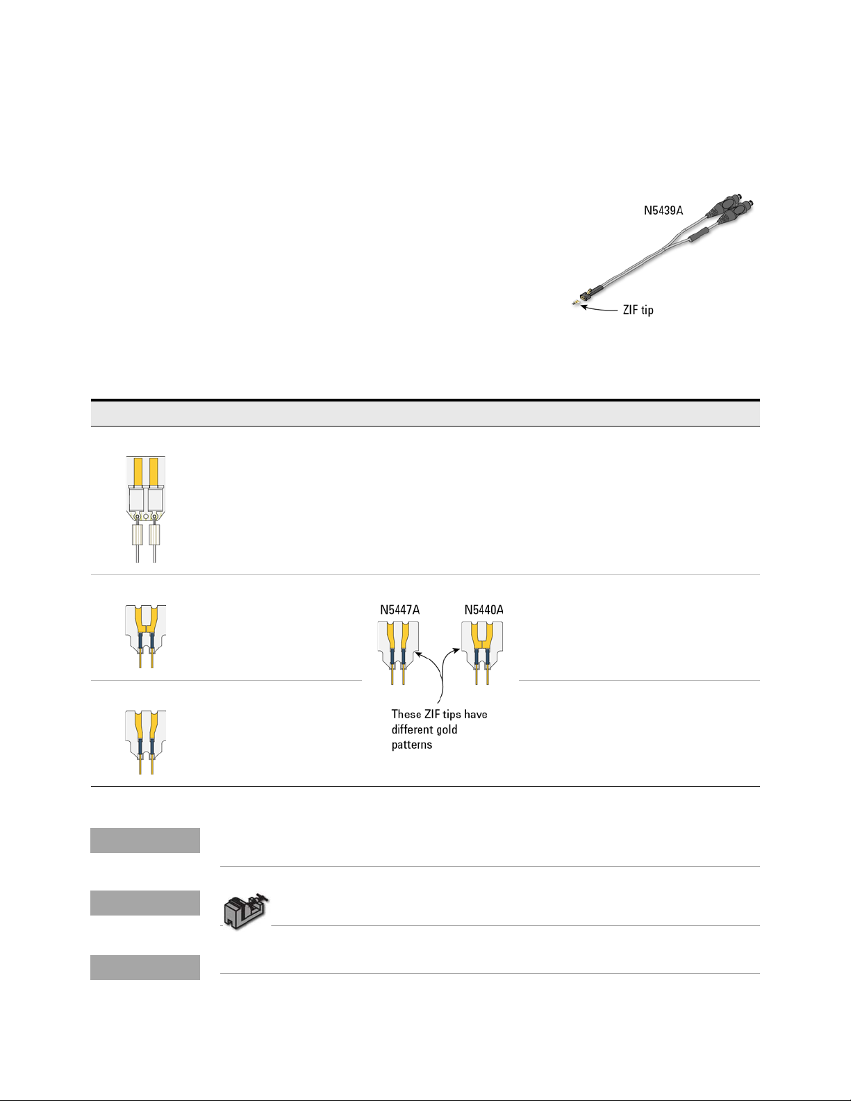
The N5439A Zero Insertion Force (ZIF) probe head
provides 28 GHz bandwidth. The head supports three
types of economical replaceable tips which are shown in
Table 3. Solder as many tips onto your DUT as needed.
Because of the ZIF tip’s extremely low loading, the tips
can remain on the DUT as you easily move the probe
head from one probing site to the next.
For information on mechanically securing the probes to
protect your equipment and designs from damage, refer to “Strain Relieving the Probe
Heads" on page 46.
Table 3 Available ZIF Tips
ZIF Tip Description Variable Tip Spacing Qty
N2838A 25 GHz 450W PC board tip provides robust design with
high bandwidth.
N5440A 28 GHz 450W ceramic
(normal sensitivity) for
extremely low probe
loading.
N5447A 28 GHz 450W ceramic
high-sensitivity for
extremely low probe
loading.
The N5439A does not include any ZIF tips. You must order either the N2838A, N5440A, or
N5447A in addition to N5439A.
5 mil to 250 mil
(0.127 mm to 6.35 mm).
5 mil to 80 mil
(0.127 mm to 2 mm).
5 mil to 80 mil
(0.127 mm to 2 mm).
5
5
5
To install or repair the N2838A resistor leads, refer to “Replacing Axial Resistor
Tips" on page 50.
For performance plots, refer to Chapter 7, “Performance Plots.
InfiniiMax III Series Probes User’s Guide 29
Page 30
2 InfiniiMax III Probe Heads
CAUTION
Ensuring Maximum N2838A Tip Performance
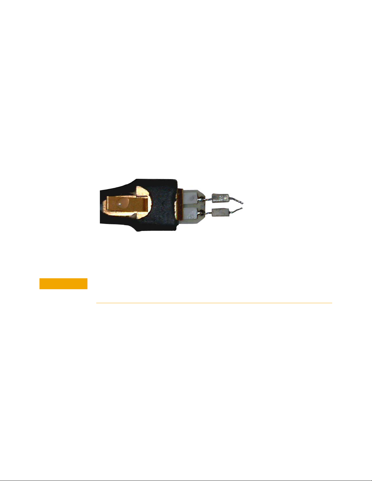
The specifications and performance plots of the N2838A ZIF tip were measured
with a nominal spacing of 40 mil (1 mm). In order to achieve the proper response
as shown in the performance plots, keep the mini-axial lead resistors roughly
parallel as shown in Figure 22, and use the tip wires on the mini-axial leads to get
the desired span.
If you need to position the resistors different than shown in this figure (that is,
resistor bodies close together or spread apart), use Keysight’s N2807A and
N2808A PrecisionProbe products to perform an AC calibration of the probe, which
properly captures the response. Increasing the spacing to 250 mil degrades the
performance some, but PrecisionProbe can be used to compensate or qualify the
effect.
Figure 22 Proper Position of Resistors
Soldering a ZIF Tip to the DUT
The ZIF tips are very fragile. They must be manufactured in this way in order to meet the
high-performance, high bandwidth applications they are intended for. Be extremely careful
when handling.
30 InfiniiMax III Series Probes User’s Guide
Page 31
InfiniiMax III Probe Heads 2
NOTE
CAUTION
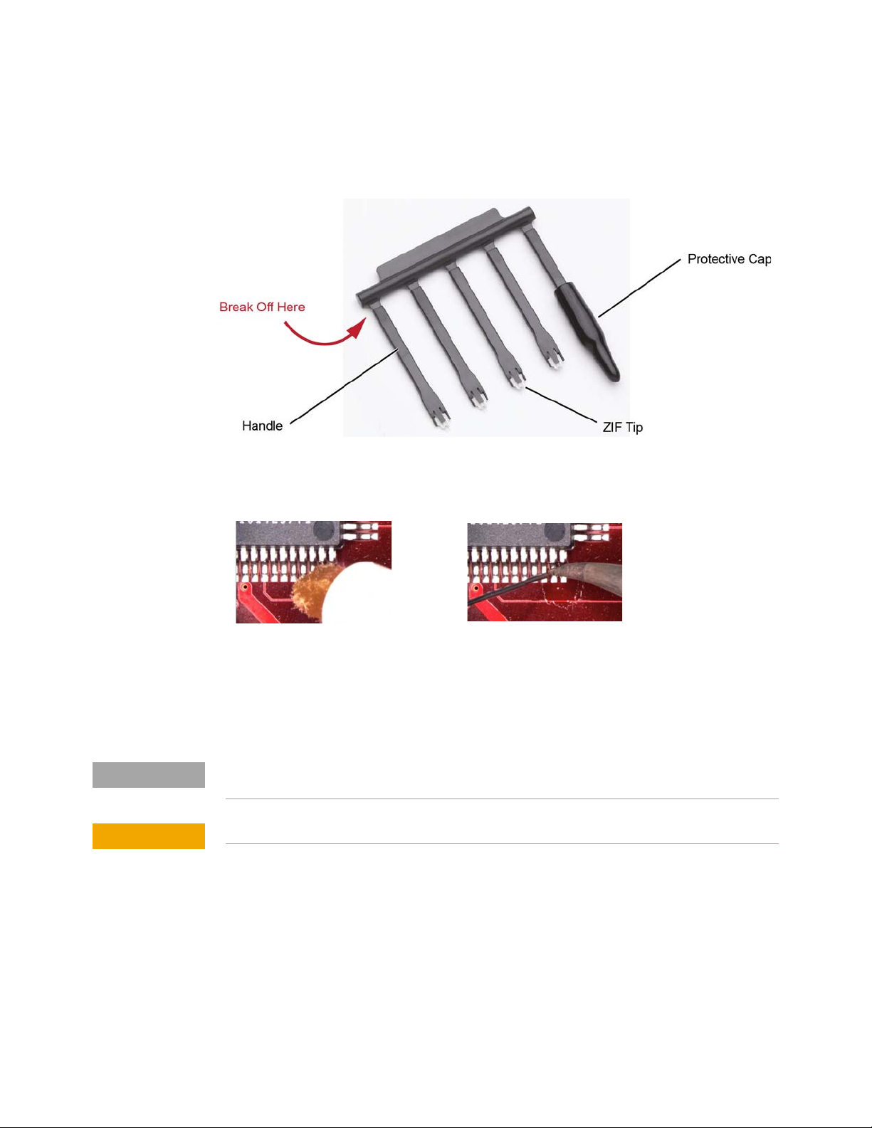
1 Break off a ZIF tip/handle combination from the packaging holder at the point shown in the
figure.
Figure 23 Five ZIF Tips on Packaging
2 Flux and tin the leads on the target DUT.
Figure 24 Preparing the DUT Leads
3 While holding the plastic form, form the ZIF tip wires to match the DUT’s pitch and angle.
4 Flux the ZIF tip wires and DUT leads.
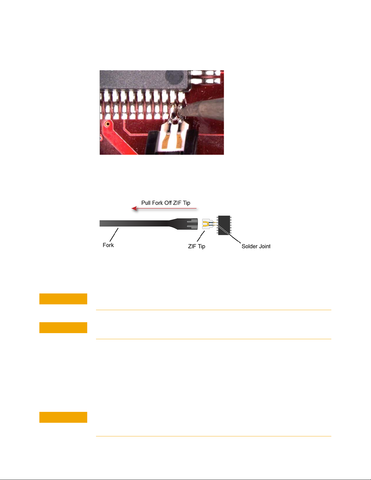
5 Position the ZIF tip with the gold traces facing up as shown in Figure 25 and carefully
re-flow the solder. This orients the tip so that it will properly mate with the probe head.
When soldering the tip to your DUT, use the tip handle to hold the tip. This allows you to position these
small tips without damaging them.
Do not dwell on this solder joint.
InfiniiMax III Series Probes User’s Guide 31
Page 32
2 InfiniiMax III Probe Heads
CAUTION
CAUTION
CAUTION
Figure 25 Soldering the ZIF Tip
6 Pull the ZIF handle from the ZIF tip in the direction shown in Figure 26. ZIF tips can be
carefully handled with your fingertips and reinserted into a plastic handle if necessary.
Figure 26 Removing the Handle from the ZIF Tip
7 You can connect ZIF tips to any of the locations on a DUT that you need to probe. The
probe head can be quickly moved between the tips.
Always mechanically strain-relieve the ZIF head before using to protect both your probe
accessories and DUT from damage. Refer to “Strain Relieving the Probe Heads" on page 46.
Be careful not to damage the tip wires when handling the ZIF tips. Wires can be carefully
reshaped with tweezers or fingers if necessary.
Connecting the Probe Head to the ZIF Tip
1 Add strain relieve for the ZIF probe head as described in “Strain Relieving the Probe
Heads" on page 46.
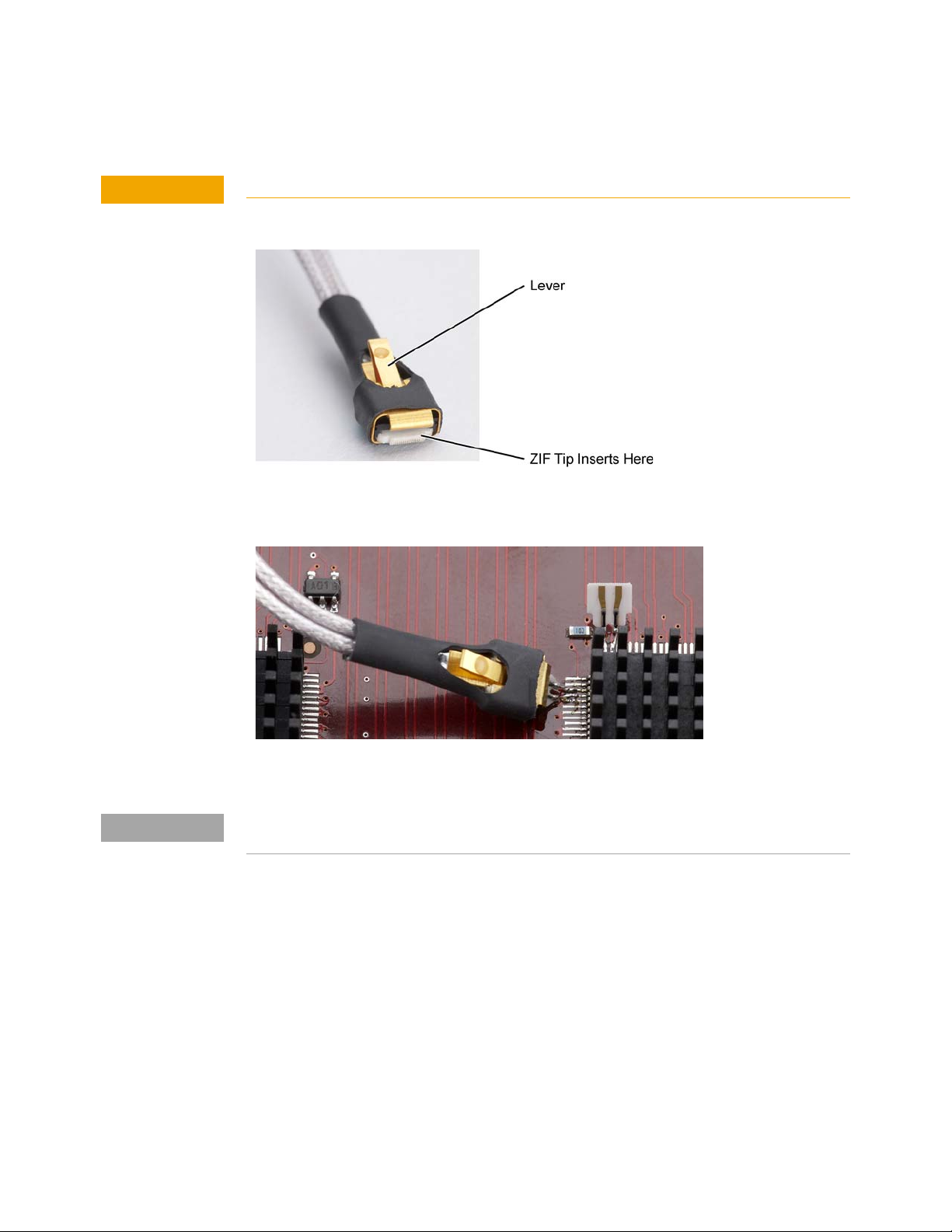
2 Form the coaxial cables to bring the probe head near the tip. Press the lever down on the
ZIF probe head (see Figure 27) and slide the probe head onto the tip. Pressing on this lever
removes the clamping force of the connector and enables you to insert or remove ZIF tips.
Stop if you encounter any resistance at all when sliding the probe head over the ZIF tip. Check
your alignment, make sure the lever is pressed, and try again. Inserting the ZIF tip should
require “zero” insertion force.
32 InfiniiMax III Series Probes User’s Guide
Page 33
CAUTION
Always use the lever when inserting or removing ZIF tips.
NOTE
Figure 27 Probe Head with Location of the Lever
InfiniiMax III Probe Heads 2
Figure 28 Probe Head Connected to a Soldered ZIF Tip
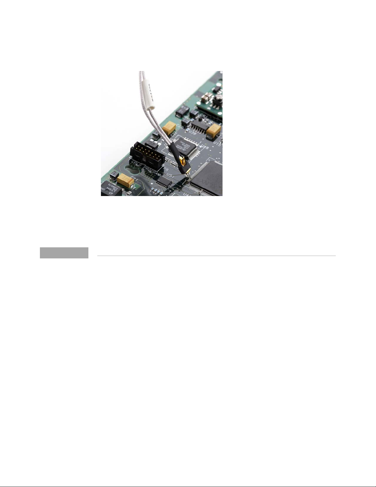
For more repeatable results, orient the probe connection perpendicular to the device as shown in
Figure 29.
InfiniiMax III Series Probes User’s Guide 33
Page 34
2 InfiniiMax III Probe Heads
NOTE
Figure 29 Probe Oriented Perpendicular to Device
3 To move the probe head to a different tip, press the lever and remove the probe head from
the ZIF tip. The ZIF tip remains soldered to the DUT. Then, simply connect the ZIF head to
another ZIF tip at a different location on the DUT.
You can use tweezers to actuate the lever in tight places.
34 InfiniiMax III Series Probes User’s Guide
Page 35
N2836A InfiniiMax III Solder-in Probe Head
NOTE
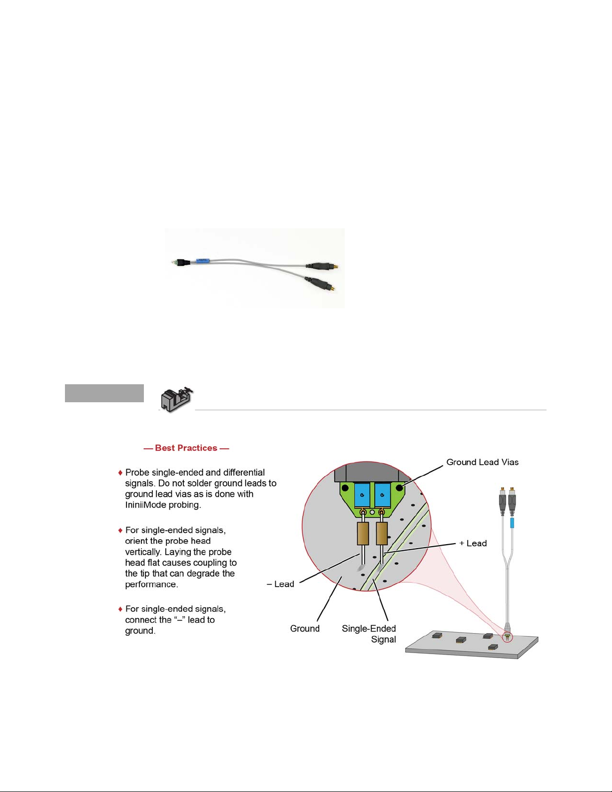
The N2836A InfiniiMax III solder-in probe head is an economical semi-permanent
connection that provides up to 26 GHz of system bandwidth. The span of the leads can be
adjusted from 5 mil - 250 mil (0.127 mm - 6.35 mm).
To use the head’s InfiniiMode capability, use this head with N2830A-series probe
amplifiers. InfiniiMode allows you to make differential, common mode, and single ended
measurements without having to re-solder the tip leads.
Figure 30 N2836A InfiniiMax III solder-in probe head
InfiniiMax III Probe Heads 2
For information on mechanically securing the probes to protect your equipment and
designs from damage, refer to “Strain Relieving the Probe Heads" on page 46.
To install or repair the N2836A resistor leads, refer to “Replacing Axial Resistor
Tips" on page 50.
Figure 31 Probe Head Connection to DUT
InfiniiMax III Series Probes User’s Guide 35
Page 36
2 InfiniiMax III Probe Heads
CAUTION
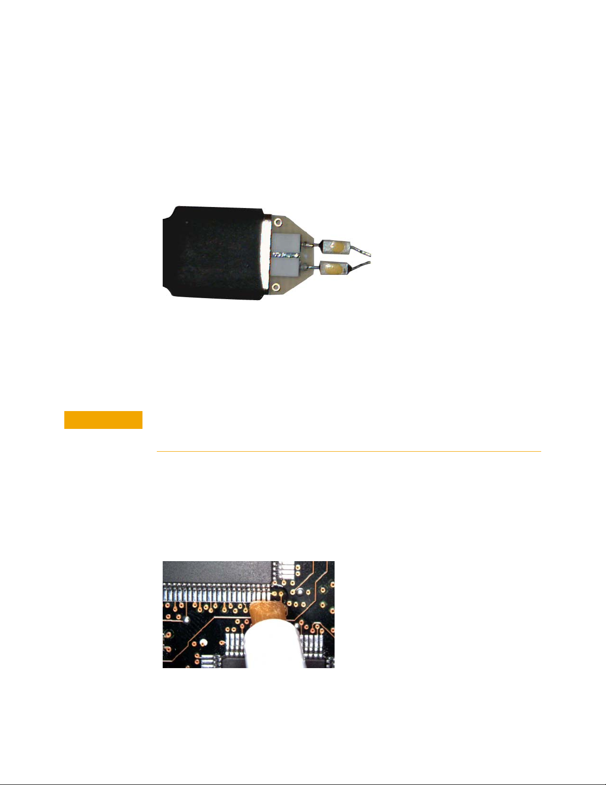
Ensuring Maximum Performance
The specifications and performance plots of the N2836A probe head were
measured with a nominal spacing of 40 mil (1 mm). In order to achieve the proper
response as shown in the performance plots, keep the mini-axial lead resisto rs
roughly parallel as shown in Figure 32, and use the tip wires on the mini-axial
leads to get the desired span.
Figure 32 N2836A With 1 mm Tip Spacing
If you need to position the mini-axial lead resistors different than shown in this figure (that
is, resistor bodies close together or spread way apart), use Keysight’s N2807A and N2808A
PrecisionProbe products to perform an AC calibration of the probe. The AC calibration will
capture the response properly. Increasing the spacing to 250 mil will degrade the
performance some, but Precision Probe can be used to compensate or qualify the effect.
The axial resistors on the N2836A solder-in probe head are fragile. They must be
manufactured in this way in order to meet the high-performance, high bandwidth applications
they are intended for. Be careful when handling.
Soldering the Probe Head to the DUT
To solder the probe head to your DUT, complete the following steps. The procedure is very
similar to that for the ZIF probe tips used with the N5439A probe head. This procedure
does not show soldering the ground leads, but the same techniques are used.
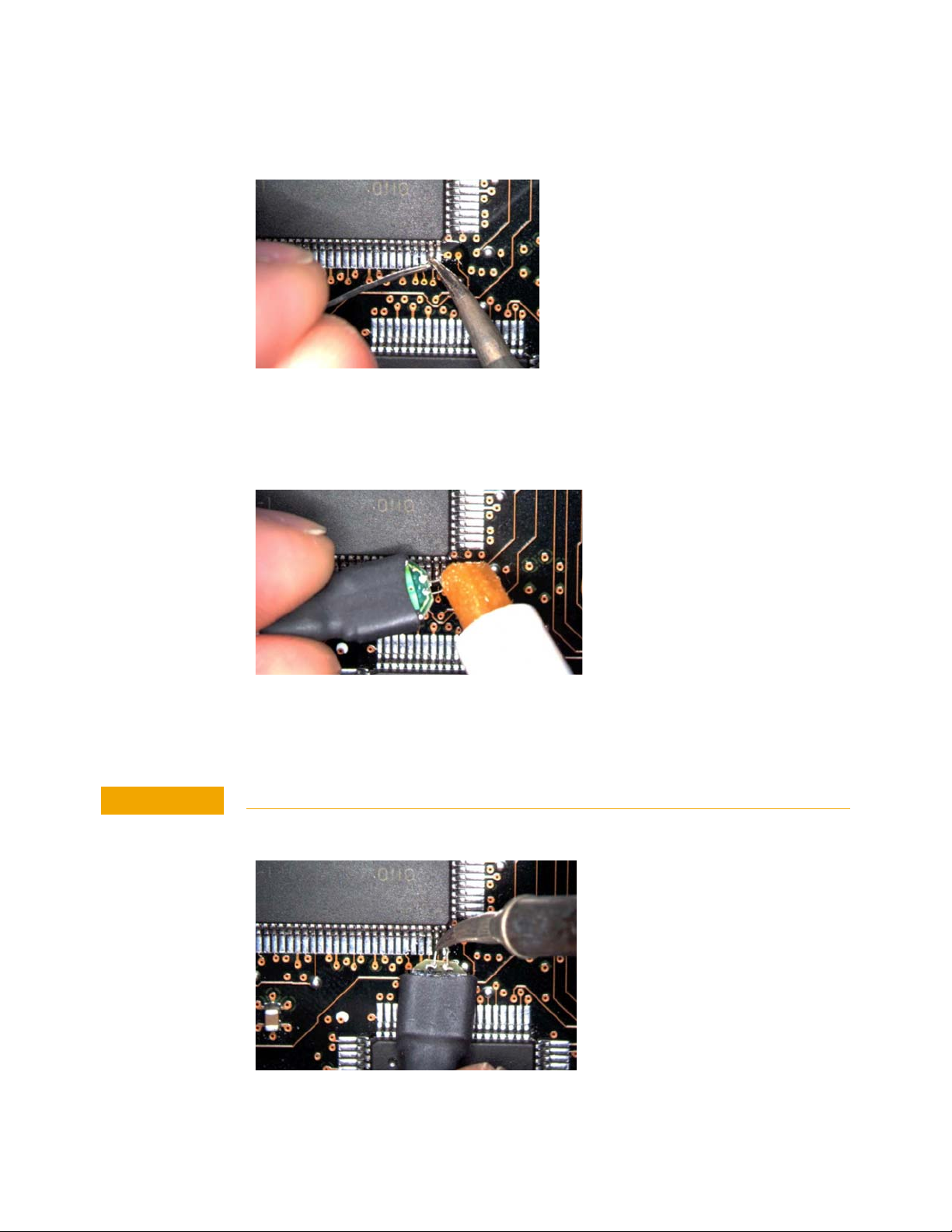
1 Apply flux to your target leads as shown in Figure 33.
Figure 33 Applying Flux
2 Tin the leads with a small amount of solder.
36 InfiniiMax III Series Probes User’s Guide
Page 37
InfiniiMax III Probe Heads 2
CAUTION
Figure 34 Tin the Leads
3 Use tweezers to form the probe head wires to fit your DUT’s geometry.
4 Flux the DUT leads and your probe head wires.
Figure 35 Applying Flux to Leads and Wires
5 Position the probe head wires on the DUT leads and quickly re-flow the solder as shown in
Figure 36.
Do not leave the iron in contact with the probe head for more than a few seconds at a time.
Figure 36 Positioning Wires
InfiniiMax III Series Probes User’s Guide 37
Page 38

2 InfiniiMax III Probe Heads
38 InfiniiMax III Series Probes User’s Guide
Page 39

N5441A InfiniiMax III Solder-in Probe Head
CAUTION
CAUTION
NOTE
The N5441A InfiniiMax III solder-in probe head is an economical semi-permanent
connection that provides up to 16 GHz of system bandwidth. The span of the leads can be
adjusted from 5 mil - 80 mil (0.127 mm - 2 mm).
The N5441A probe head can be used with the N5450B InfiniiMax extreme temperature
extension cable. This is the only InfiniiMax III probe head that can withstand the –55°C to
+150°C extreme temperature range (for up to 250 test cycles).
When using the N5450B extension cable, do not subject the InfiniiMax III probe amplifier or
probe head (other than the N5441A solder-in probe head) to extreme temperatures.
InfiniiMax III Probe Heads 2
Figure 37 N5441A InfiniiMax III solder-in probe head
The wires on the N5441A are fragile. They must be manufactured in this way in order to meet
the high-performance, high bandwidth applications they are intended for. Be careful when
handling.
For information on mechanically securing the probes to protect your equipment and
designs from damage, refer to “Strain Relieving the Probe Heads" on page 46.
To install or repair the tip wires on the N5441A, refer to “Replacing N5441A Probe
Head Wires" on page 53.
Soldering the Probe Head to the DUT
To solder the probe head to your DUT, complete the following steps. The procedure is very
similar to that for the ZIF probe tips used with the N5439A probe head.
1 Position the probe head near the location on the DUT where you want to solder the probe.
2 Add strain relieve for the probe head as described in “Strain Relieving the Probe
Heads" on page 46.
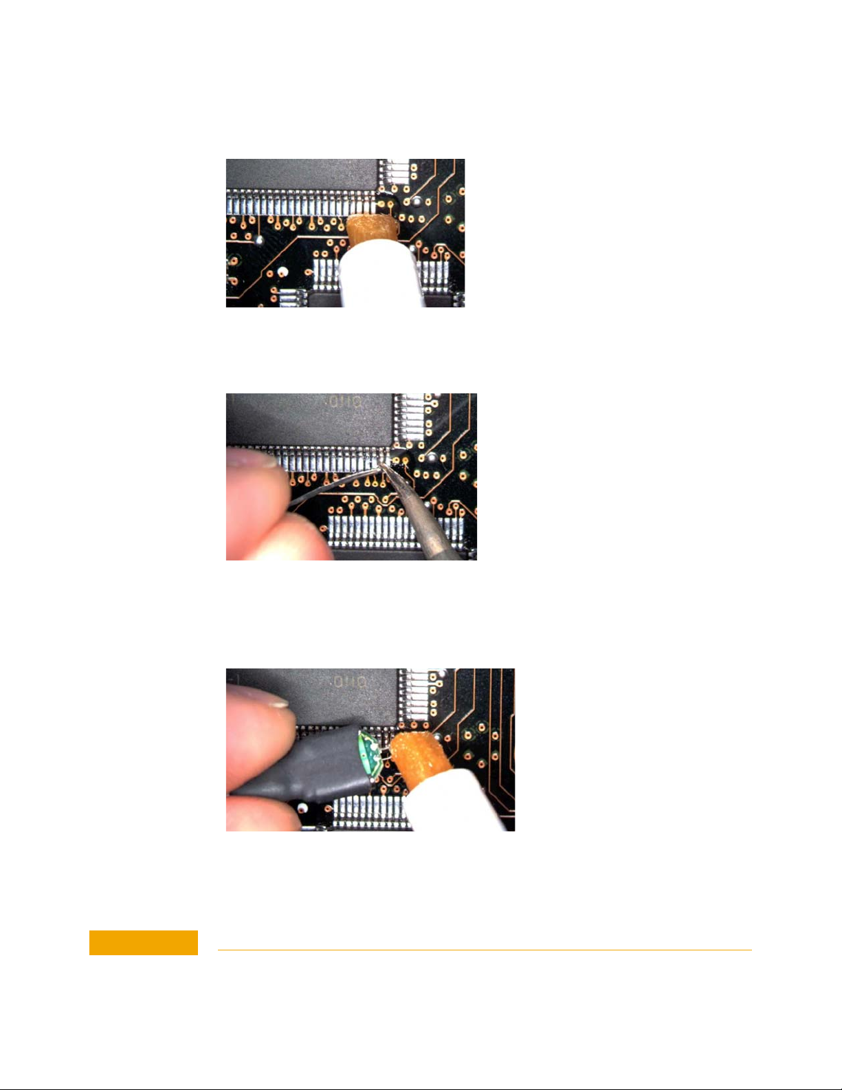
3 Apply flux to your target leads as shown in Figure 38.
InfiniiMax III Series Probes User’s Guide 39
Page 40
2 InfiniiMax III Probe Heads
CAUTION
Figure 38 Applying Flux
4 Tin the leads with a small amount of solder.
Figure 39 Tin the Leads
5 Use tweezers to form the probe head wires to fit your DUT’s geometry.
6 Flux the DUT leads and your probe head wires.
Figure 40 Applying Flux to Leads and Wires
7 Position the probe head wires on the DUT leads and quickly re-flow the solder as shown in
Figure 41.
Do not leave the iron in contact with the probe head for more than a few seconds at a time.
40 InfiniiMax III Series Probes User’s Guide
Page 41
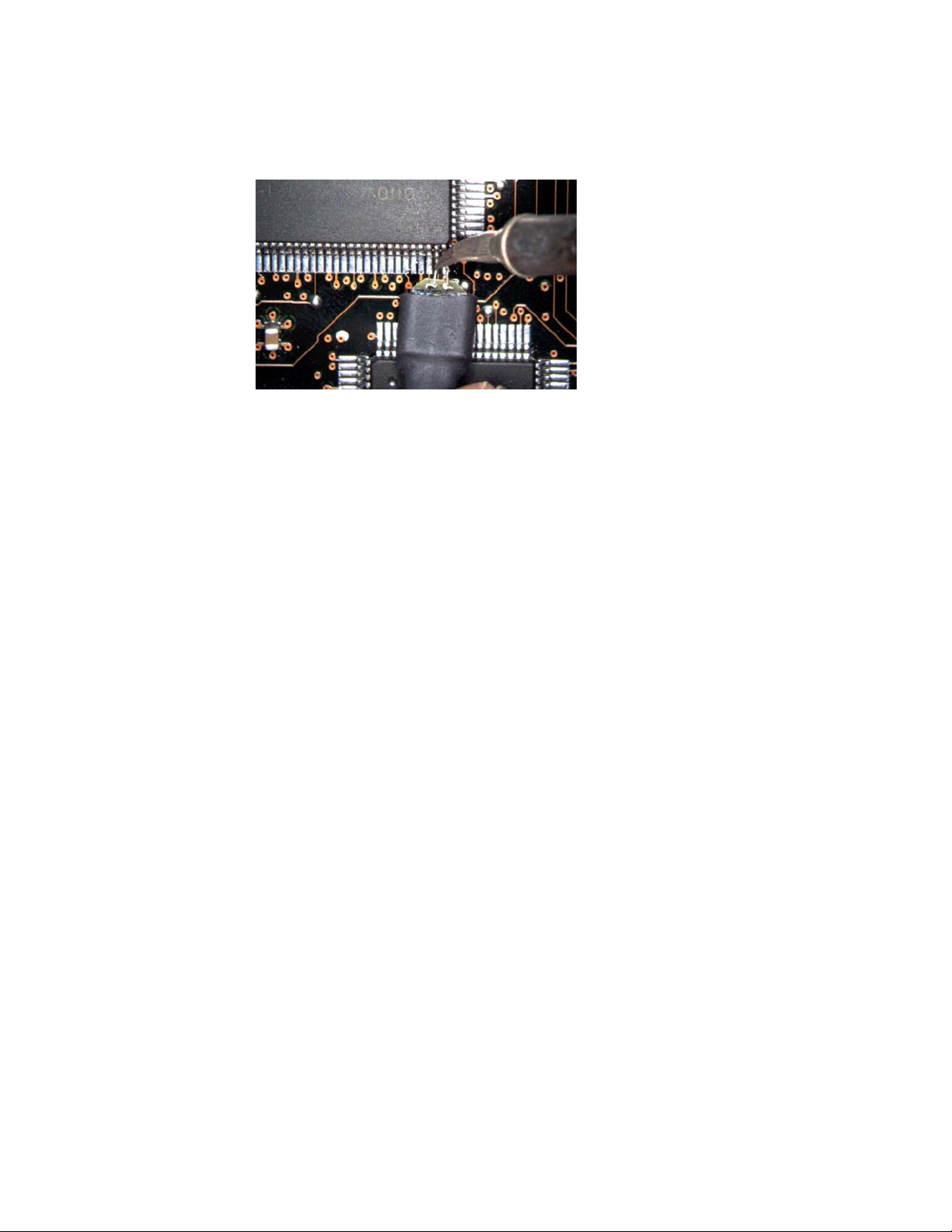
Figure 41 Positioning Wires
InfiniiMax III Probe Heads 2
InfiniiMax III Series Probes User’s Guide 41
Page 42
2 InfiniiMax III Probe Heads
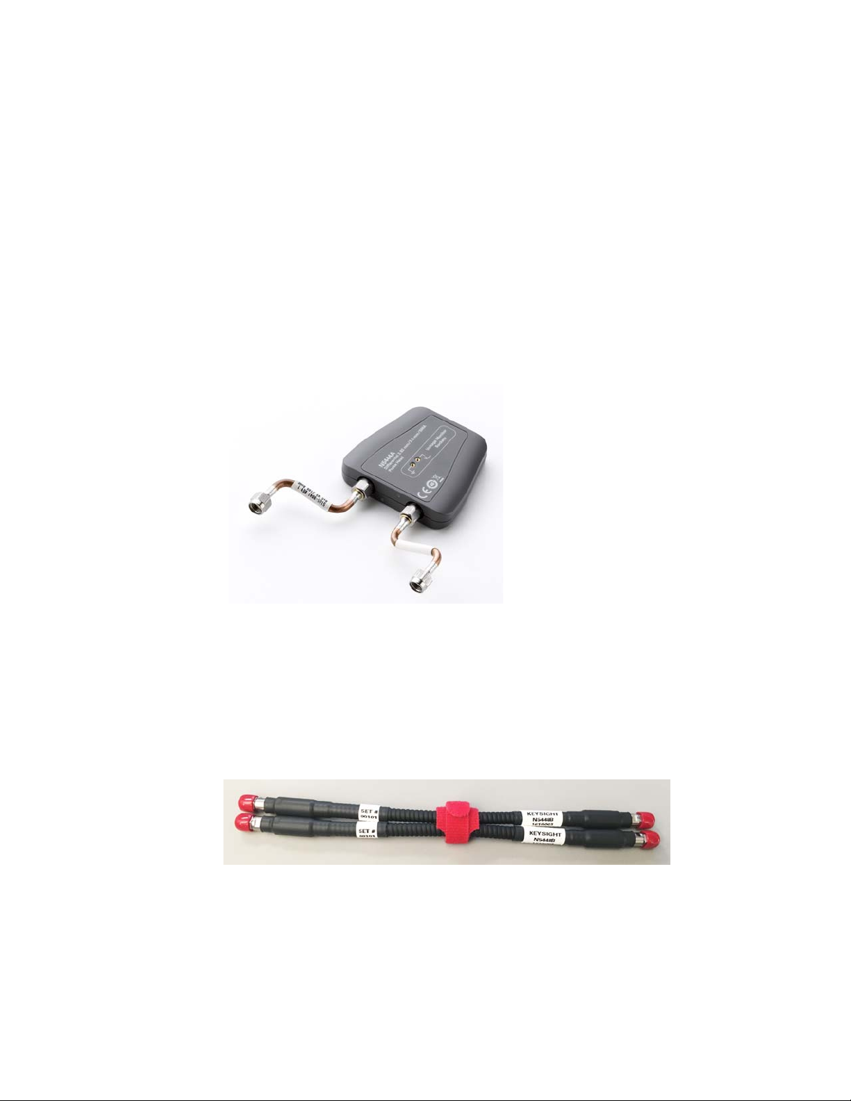
N5444A InfiniiMax III 2.92 mm / 3.5 mm / SMA Probe Head
The N5444A InfiniiMax III 2.92 mm/3.5 mm/SMA probe head provides 30 GHz bandwidth
and allows you to connect two 2.92 mm, 3.5 mm, or SMA cables to make a differential
measurement on a single oscilloscope channel.
The N5444A provides for a termination to a common DC voltage rather than to ground,
which is required for many signal standards. It is implemented such that from DC to
approximately 1 kHz, the termination is 55 Ohms to the termination voltage, and above
approximately 10 kHz, the termination is 50 Ohms to 0.9 times the termination voltage.
The termination voltage range is ±4V with a minimum step of 5 mV and a maximum
current of 80 mA. The termination voltage can be controlled internally by the oscilloscope
or applied externally using the supplied DC jack.
Figure 42 N5444A InfiniiMax III 2.92mm/3.5mm/SMA Probe Head
N5448B Coaxial Phase Matched Cable Pair
For extending the cable length of the N5444A InfiniiMax III probe head and add flexibility
and convenience to the probing setup, you can order N5448B 10 inches (25 cm) long
coaxial phase matched cable pair. This cable pair supports 2.92 mm male-to-2.92 mm
male connection.
Figure 43 N5448B Coaxial Phase Matched Cable Pair
Before connecting these cables to the N5444A probe head, you must first remove the
supplied rigid cables of the N5444A probe head. Figure 44 on page 43 shows the N5448B
cables attached to the N5444A probe head.
42 InfiniiMax III Series Probes User’s Guide
Page 43
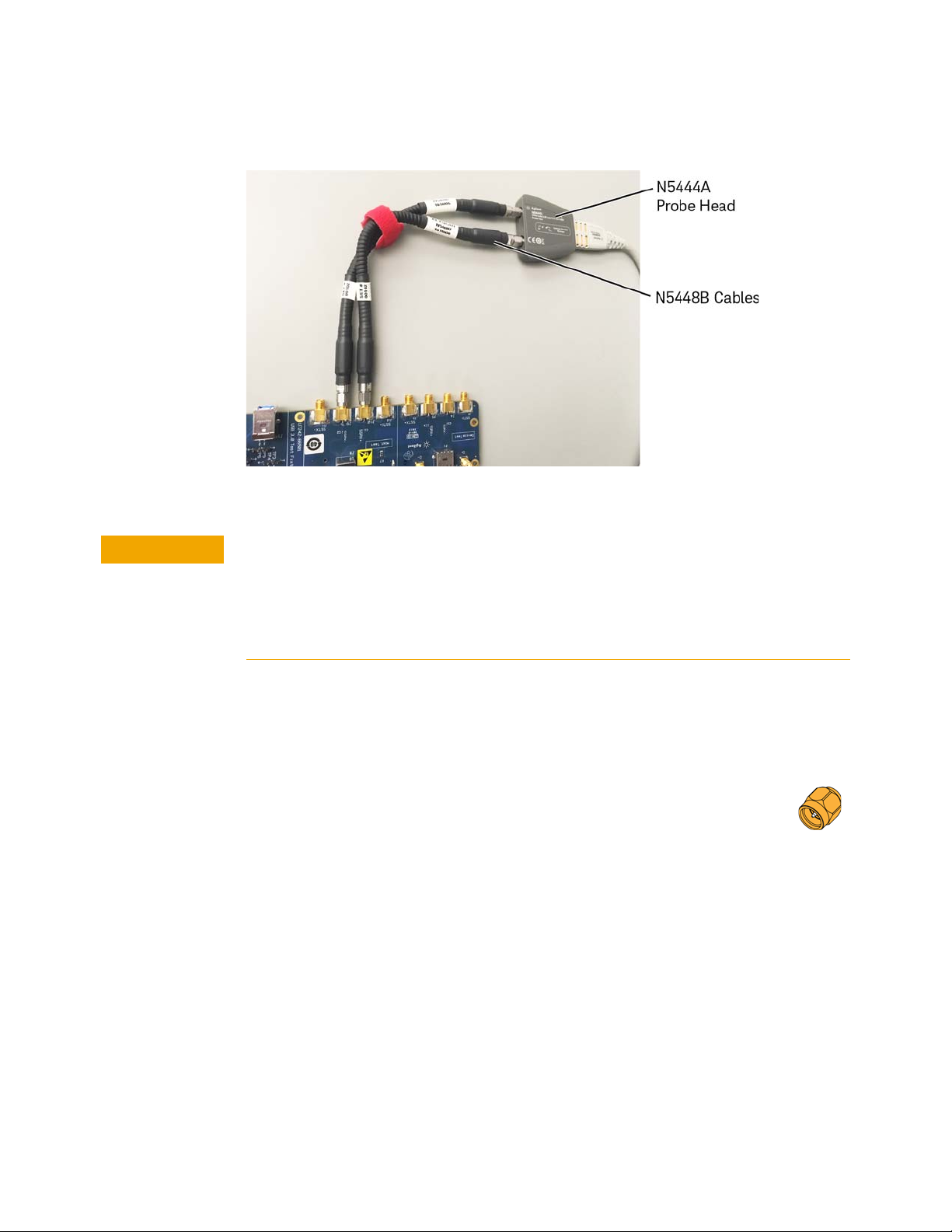
Figure 44 N5444A Probe Head With N5448B Cables Attached
CAUTION
InfiniiMax III Probe Heads 2
The maximum bend radius for the N5448B coaxial cable pair is 30 mm. Bending these
cables at too tight a radius or twisting the cables can cause damage, reduce
performance, and impact the precision of these cables.
Also, ensure that the plastic caps that are provided with these cables are installed
when the cables are not in use.
For details on the N5448B cable, refer to its guide available in the Document Library tab of
this product’s page on www.keysight.com.
Probe Offset Calibration with the N5444A
To achieve more accurate probe offset calibration with the N5444A, an SMA
shorting adapter (Keysight part number: 1250-3999) is required. This adapter is
provided with the N5444A (with unit serial number US50072545 or higher) and
should be connected to the N5444A's "—" input connector during the calibration.
The latest Infiniium firmware includes instructions on the Probe Calibration dialog box to
remind you to install the adapter. If the Infiniium oscilloscope's firmware is older than
version 5.50.33, you can still attach the adapter and the resulting calibration will be valid.
InfiniiMax III Series Probes User’s Guide 43
Page 44
2 InfiniiMax III Probe Heads
N2835A InfiniiMax III Differential Connectivity Kit and Accessories
In addition to the individual probe heads described in the previous topics, the
N2835A differential connectivity kit is also available for the InfiniiMax III probes.
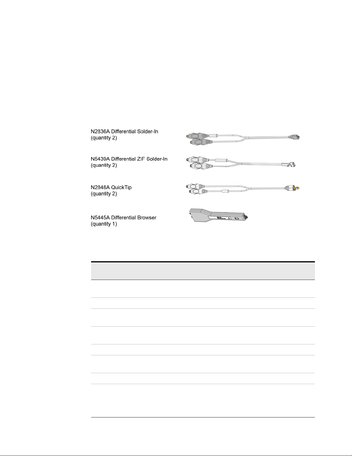
This kit provides multiple quantities of the four InfiniiMax III probe heads as shown
in Figure 45. You can order this kit either at the same time as InfiniiMax III probe
amplifiers or separately later.
Figure 45 Probe Heads Included in the N2835A Differential Connectivity Kit (not to scale)
Table 4 Supplied Accessories (Sheet 1 of 2)
Qty
Description
N2836A InfiniiMax III 26 GHz Differential Solder-In Probe
Head
Replacement Axial Resistors Kit 10 N2836-68701
N5439A InfiniiMax III 28 GHz Differential ZIF Solder-in Probe
Head
N2838A InfiniiMax III 25 GHz ZIF Tip Kit 2 kits (5 tips in
N2848A InfiniiMax III QuickTip Probe Head 2 N2848A
N2849A InfiniiMax QuickTip Tips Kit 2 kits (4 tips in
N5445A InfiniiMax III Browser Probe Head 1 N5445A
Replacement Tips
Tweezer for replacing tips
Screw Driver
Protective End Cap
Supplied
2 N2836A
2 N5439A
each kit)
each kit)
4
1
1
1
Part
Number
N2838A
N2849A
N5476A
N5445-23801
N5445-23802
N5445-44101
44 InfiniiMax III Series Probes User’s Guide
Page 45

Table 4 Supplied Accessories (Sheet 2 of 2)
InfiniiMax III Probe Heads 2
Description
Qty
Supplied
Ground Blades 4 N5445-68700
Part
Number
InfiniiMax III Series Probes User’s Guide 45
Page 46
2 InfiniiMax III Probe Heads
Strain Relieving the Probe Heads
High-performance probes have small physical geometries to ensure the lowest possible
loading and best electrical response. Because of their small size, probing accessories are
often delicate. It is important to mechanically secure your probes to protect both your
equipment and designs from damage. There are several methods that Keysight
recommends:
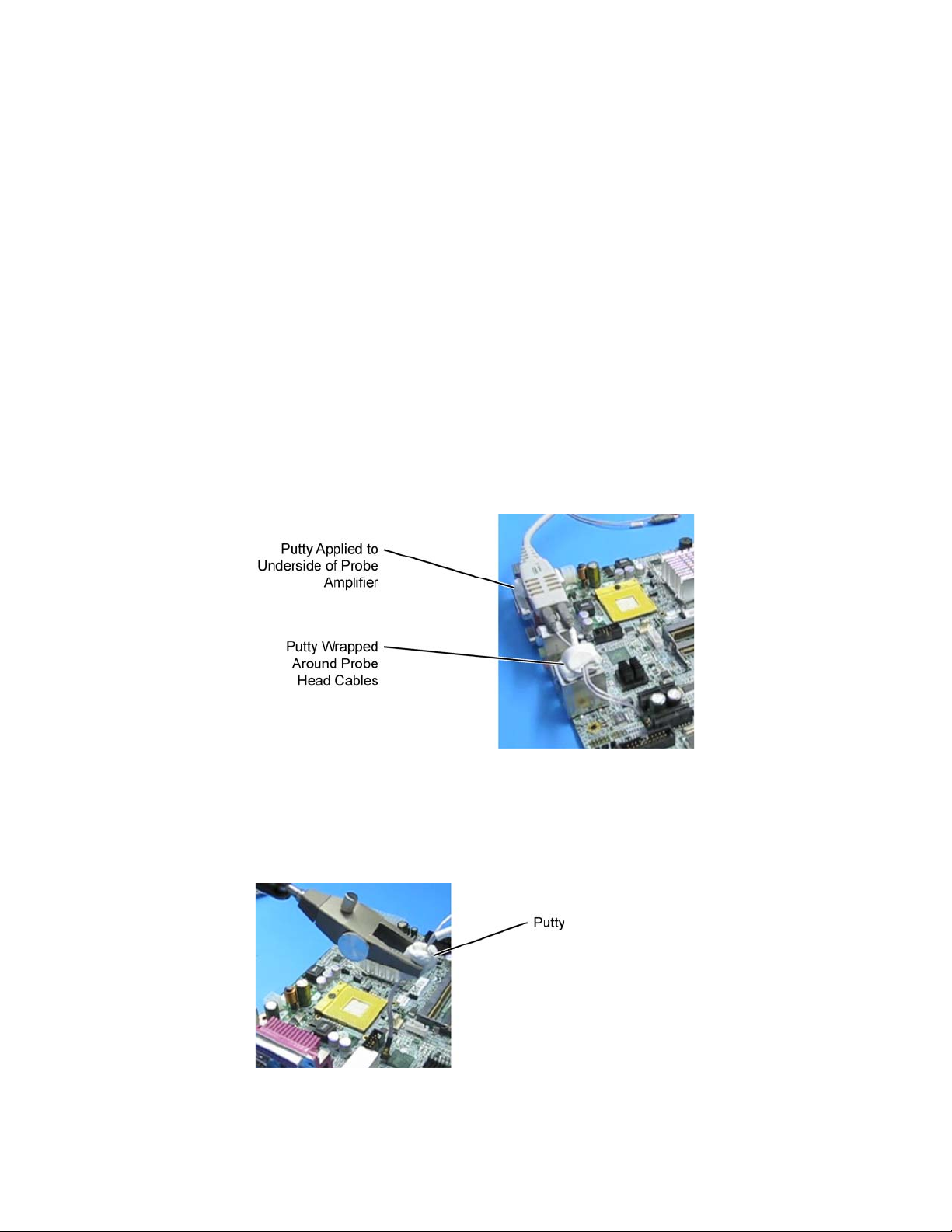
Tack-putty
Keysight recommends the use of tack-putty for securing both probe heads and amplifiers.
Wrap a small amount of tack-putty around your probe head cables, taking care to not
pinch them. The mass can then be secured to a rigid body neat your DUT.
A similar techniques can be used to secure probe amplifiers where you apply some
tack-putty to the underside of the probe amplifier body and attach it to a rigid body near
your DUT.
Figure 46 Using tack-putty to strain relieve a probe head and amplifier
You can also use putty with a positioner, such as the Keysight N2787A. The same
positioner can also be used to support your probe amplifier as shown in Figure 18 on
page 24.
Figure 47 Using putty with the N2787A 3D Probe Positioner
46 InfiniiMax III Series Probes User’s Guide
Page 47
Low-temperature Hot Glue
CAUTION
CAUTION
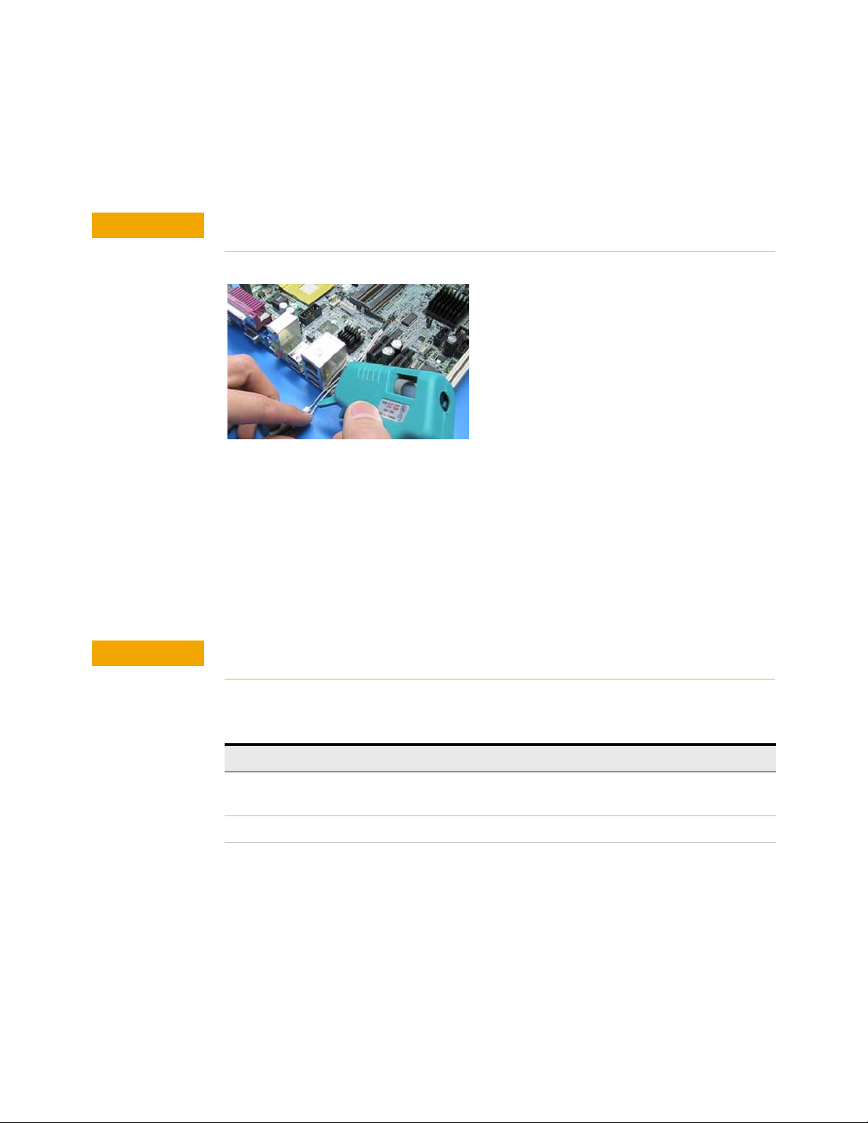
You can also use low-temperature hot glue to secure cables.
Only use LOW temperature hot glue. To remove the hot glue, warm it with a heat gun set on
low. Only heat the hot glue enough to remove it.
Figure 48 Using low-temperature hot glue to secure a probe head
InfiniiMax III Probe Heads 2
General Tips on Strain Relief
Keep in mind that different accessories have different cable stiffness. You should choose a
strain relief method appropriate for the cable stiffness. For instance, it is best to secure the
stiffer N5439A near the SMP connectors and form the cable to the optimal location.
Other strain-relief options like tape or hook-and-loop work fine as well, but keep the
following guidelines in mind to protect your probing investment.
Do not kink cables. Do not crush cables. Do not use aggressive adhesives or high
temperatures.
Table 5 Replaceable Parts
Part Part Number
Extra wire (for solder-in probe head only) 01169-81301 (7 mil)
Strain Relief Putty N5439-65201
01169-21306 (5 mil)
InfiniiMax III Series Probes User’s Guide 47
Page 48

2 InfiniiMax III Probe Heads
48 InfiniiMax III Series Probes User’s Guide
Page 49

Keysight InfiniiMax III Series Probes
CAUTION
User’s Guide
3 Maintaining Probe Heads
Replacing Axial Resistor Tips 50
Replacing N5441A Probe Head Wires 53
Many probe heads come equipped with replaceable resistor or wire tips which can
be replaced or repaired. Using the procedures in this chapter, you can extend the
life of the following items:
• N2836A probe heads
• N5441A probe heads
• N2838A ZIF tips
Do not replace or repair the N2849A QuickTip’s resistor or ground leads. Attempting to do so
will damage the ability of the tip to mate with the N2848A probe head.
49
Page 50

3 Maintaining Probe Heads
NOTE
CAUTION
CAUTION
Replacing Axial Resistor Tips
The procedure in this sections shows you how to replace the 130 ohm axial resistors that
are located at the tip of the
• N2836A solder-in probe head and
• N2838A ZIF tip.
• These resistors can become worn or damaged with use. Order the replacement axial
resistor kit (N2836-68701) which provides 10 resistors.
The pictures in the following procedure show the N2836A solder-in probe head, but the same
procedure applies to the N2838A ZIF tip.
Recommended Equipment
• Vise or clamp for holding tip.
• Metcal STTC-022 (600 °C) or STTC-122(700 °C) tip soldering iron or equivalent. The
600 °C tip will help limit burning of the FR4 tip PC board.
• 0.381 mm (0.015 in) diameter RMA flux standard tin/lead solder wire.
• Fine stainless steel tweezers.
• Rosin flux pencil, RMA type (Kester #186 or equivalent).
• Diagonal cutters.
• Magnifier or low power microscope.
•Ruler.
Procedure
1 As shown in Figure 49, clamp the probe head or ZIF tip in a vise. Tweezers can be used to
As the probe heads and tips are easily damaged, only experienced soldering technicians
should attempt this repair.
hold the probe head or ZIF tip away from the vise. When using tweezers, grip the tip either
on the sides or top and bottom.
When tightening the vise, use light force to avoid damaging the solder-in probe head.
50 InfiniiMax III Series Probes User’s Guide
Page 51
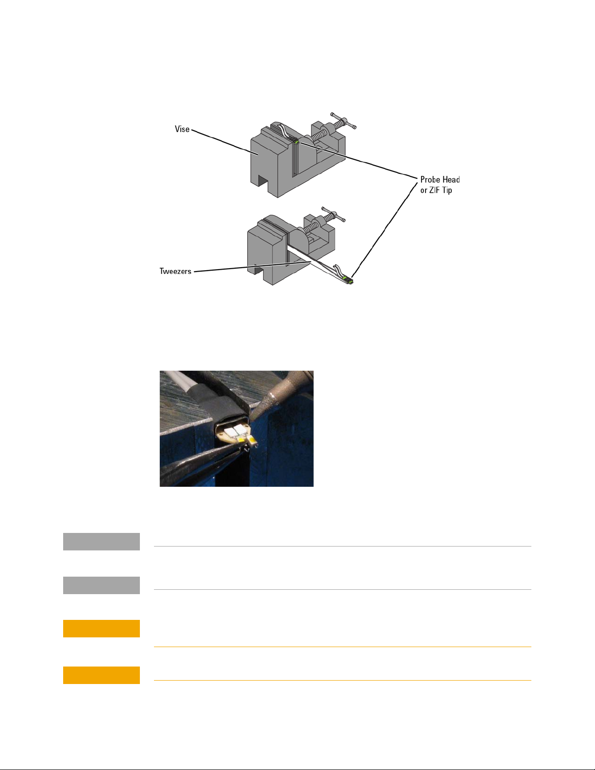
Figure 49 Clamping the Part
NOTE
NOTE
CAUTION
CAUTION
Maintaining Probe Heads 3
2 Grab each resistor lead or wire with tweezers and pull very gently up. Touch the soldering
iron to solder joint just long enough for the resistor to come free of the probe head tip.
Figure 50 Removing the Resistor
Clean the soldering iron tip of any excess solder before using.
The solder joint has very low thermal mass so the joint will quickly melt and release.
To limit burning and damage to the PC board, do not keep the soldering iron in contact with
the tip any longer than is necessary.
Excessive dwell time with the iron will permanently damage the flip-chip resistor.
InfiniiMax III Series Probes User’s Guide 51
Page 52
3 Maintaining Probe Heads
CAUTION
CAUTION
NOTE
3 Use the soldering iron and solder to fill the holes in preparation for mounting the new
resistors (or wires).
Do not leave the iron in contact with the tip any longer than necessary.
4 Use the flux pencil to coat the solder joint area with flux.
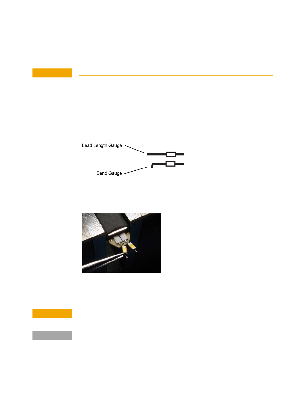
5 Locate the trim gauge which is supplied with the N2836-68701 replacement axial resistor
kit.
a
Place a resistor over the lead length gauge shown in Figure 51. Trim the
leads to match the drawing. The orientation of the lead is not important.
b Place a resistor over the bend gauge and bend the leads to match the
drawing. This bend fits in the hole in the tip’s PC board.
Figure 51 Trim Guage
6 Holding the resistor lead or wire in one hand and soldering iron in the other, position the
end of the resistor lead (after the 90 degree bend) over the solder filled hole.
Figure 52 Soldering in a new axial resistor
7 Touch the soldering iron to the side of the hole. When the solder in the hole melts, the
resistor lead will fall into the hole.
Remove the soldering iron as soon as the lead falls into the hole.
Because the thermal mass of the joint is very small, extra dwell time with the soldering iron is not
needed to ensure a good joint.
8 Using a digital volt meter, measure the resistance from the coax center conductor to the
resistor tip. The DC resistance should measure 450 ohms.
52 InfiniiMax III Series Probes User’s Guide
Page 53

Replacing N5441A Probe Head Wires
CAUTION
Use the following procedure to install or replace the wire leads on the N5441A solder-in
probe head. Depending on your probing application, you can order either 5 mil or 7 mil
wire as listed in the following table. For example, use the 5 mil wire for attaching to small
vias.
Table 6 Required Wire Type
Wire Diameter Part Number
0.007 inch (tin-plated nickel wires) 01169-81301
0.005 inch (tin-plated nickel wires) 01169-21306
Table 7 Recommended Equipment
Equipment
Maintaining Probe Heads 3
Vise or clamp for holding tip
Metcal STTC-022 (600 °C) or STTC-122 (700 °C) tip soldering iron or equivalent. The 600 °C tip will help limit burning of the
FR4 tip PC board.
0.381 mm (0.015 in) diameter RMA flux standard tin/lead solder wire
Fine stainless steel tweezers
Rosin flux pencil, RMA type (Kester #186 or equivalent)
Flush cutting wire cutters
Magnifier or low power microscope
Keysight supplied trim gauge (01169-23801)
Procedure
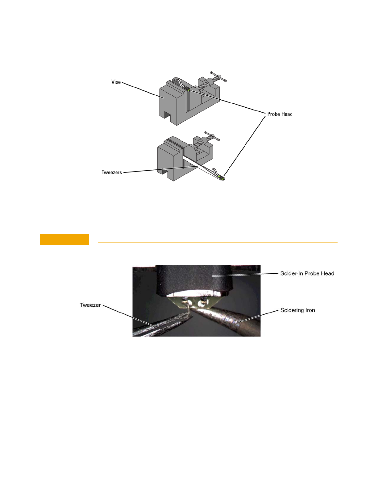
1 Use the vise or clamp to position the tip an inch or so off the work surface for easy access.
If using a vise, grip the tip on the sides with light force. When tightening the vise, use light
force to avoid damaging the solder-in probe head If using a tweezers clamp, grip the tip either
on the sides or at the top and bottom.
InfiniiMax III Series Probes User’s Guide 53
Page 54
3 Maintaining Probe Heads
CAUTION
Figure 53 Clamping the Probe Head
2 As shown in Figure 54, remove the old wires with tweezers while re-flowing the solder from
the underside of the probe.
Apply heat quickly to avoid damaging your probe.
Figure 54 Removing the Old Wire
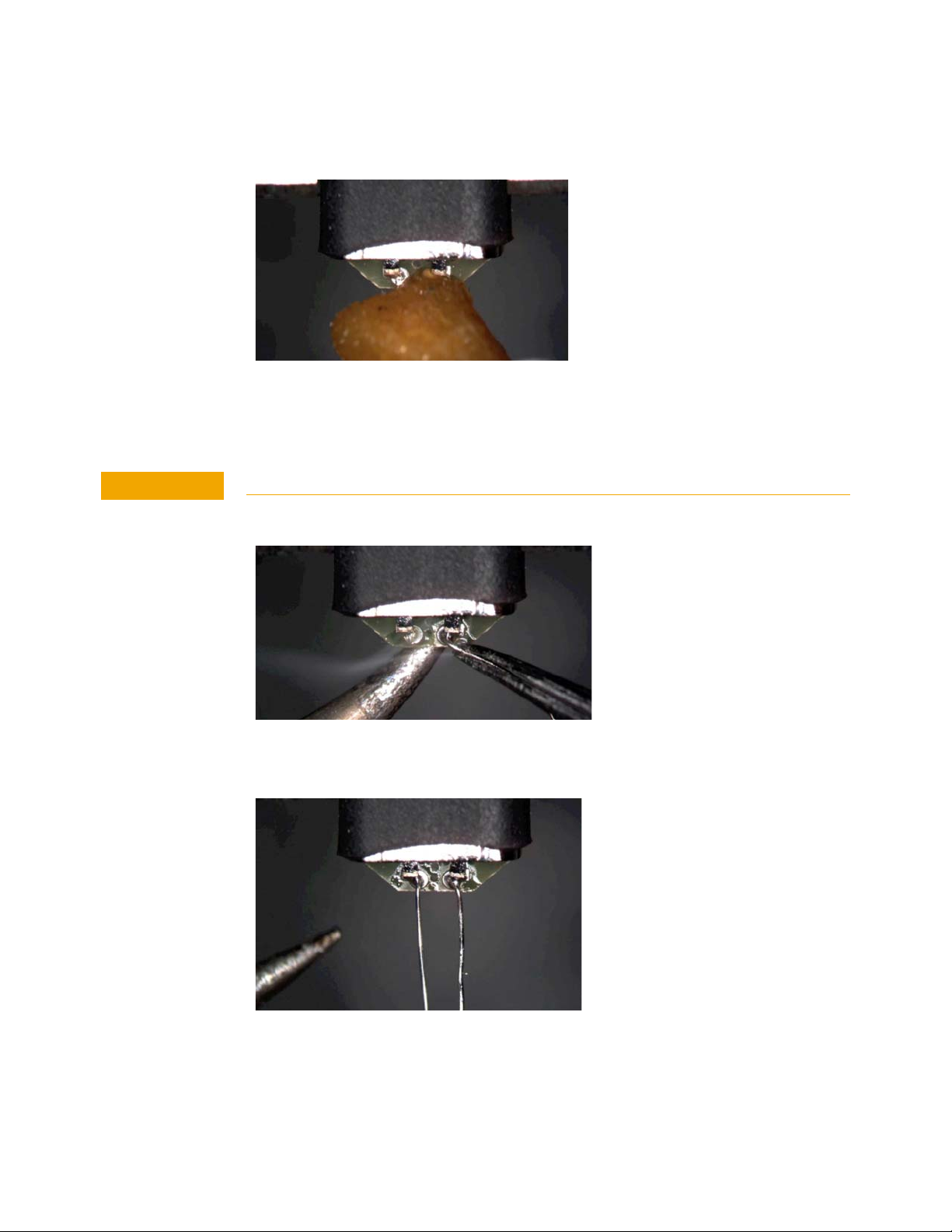
3 If necessary, add a small amount of solder to the holes and apply flux.
54 InfiniiMax III Series Probes User’s Guide
Page 55
Maintaining Probe Heads 3
CAUTION
Figure 55 Adding Solder and Flux
4 Re-flow the solder from the underside and insert a new piece of wire. It is best to shape the
wire into an “L” before attempting to insert.
Do not dwell with the iron in contact with the probe head.
Figure 56 Adding a New Wire
Figure 57 New Wires Properly Attached
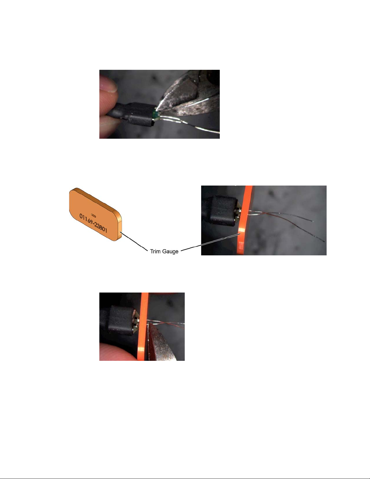
5 Trim any wire stubs on the probe head underside.
InfiniiMax III Series Probes User’s Guide 55
Page 56
3 Maintaining Probe Heads
Figure 58 Trim Wire Stubs
6 Use the included trim gauge to cut the wire lengths. Doing so ensures the best
performance from your probe head.
Figure 59 Trim Gauge Placed on Wires
Figure 60 Removing Excess Wire
7 Check the DC resistance of each probe leg when you have replaced the wires. The correct
resistance should be 450 ohms.
56 InfiniiMax III Series Probes User’s Guide
Page 57

Keysight InfiniiMax III Series Probes
User’s Guide
4 Performance Specifications /
Characteristics
The InfiniiMax III series probe amplifiers and probe heads are designed to be used within
the temperature range of the 90000-X series oscilloscope. The only exception is the
N5441A solder-in probe head. The N5441A solder-in probe head temperature range is
from –55°C to +150°C for up to 250 test cycles. The N5441A is compatible with the
N5450B InfiniiMax extreme temperature extension cable.
57
Page 58

4 Performance Specifications / Characteristics
Specifications and Characteristics
Table 8 Probe Amplifiers
Probe Amplifier BW tr
N2800A 16 GHz 27.1 ps
N2801A 20 GHz 21.7 ps
N2802A 25 GHz 17.4 ps
N2803A 30 GHz 14.3 ps
58 InfiniiMax III Series Probes User’s Guide
Page 59

Performance Specifications / Characteristics 4
Table 9 N2803A Amplifier with N2836A, N5441A, and N2848A Probe Heads (Sheet 1 of 2)
Specifications / Characteristics N2836A
Solder-In
Probe Bandwidth
(–3 dB), Probe Only
Rise and Fall Time, Probe Only
(Single-Ended)
Rise and Fall Time, Probe Only
(Differential Mode)
System Bandwidth
(–3 dB) with
DSO/DSAX93204A
Rise and fall time with
DSO/DSAX93204A
Input Capacitance Cdiff = 108 fF
DC Input Resistance* Rse = 50 kΩ ±2% each
27 GHz (typical) 17.2 GHz (typical) 16 GHz (typical)
21.1 ps (10-90%)
13.8 ps (20-80%)
16.1 ps (10-90%)
11.4 ps (20-80%)
26 GHz 16 GHz
16.5 ps (10-90%)
11.7 ps (20-80%)
Cse = 140 fF
input to ground
Rdiff = 100 kΩ ±2%
Rcm = 25 kΩ ±2%
N5441A
Solder-In)
34.8 ps (10-90%)
26.6 ps (20-80%)
17.2 ps (10-90%)
26.6 ps (20-80%)
27.1 ps (10-90%)
19.2 ps (20-80%)
Cdiff = 77 fF
Cse = 105 fF
Rse = 50 kΩ ±2% each
input to ground
Rdiff = 100 kΩ ±2%
Rcm = 25 kΩ ±2%
N2848A QuickTip Head
with N2849A Tip
—
27.1 ps (10-90%)
19.3 ps (20-80%)
Cdiff = 340 fF
Cse = 200 fF
Rse = 50 kΩ ±2% each
input to ground
Rdiff = 100 kΩ ±2%
Rcm = 25 kΩ ±2%
Input Resistance (> 10 kHz) Rse = 500Ω each input to
ground
Rdiff = 1 kΩ
Rcm = 250Ω
Input Voltage Range
(Differential or Single-Ended)
Input Common Mode Range ±12V DC to 250 Hz
DC attenuation Ratio 6:1 6:1 5:1 or 10:1
Offset Range (for probing a
single-ended signal)
Input Referred Noise Spectral
Density
Input Referred Noise Example 4 mVrms 4 mVrms
*Denotes warranted characteristic - all others are typical
**Harmonic distortion < –38 dB is standard; < –34 dB wider input range with slightly increased distortion
1.6Vpp, ±0.8V
(HD2&3< –38 dBc typ.),
2.5Vpp, ±1.25V
(HD2&3< –34 dBc typ.) **
±1.25V > 250 Hz
±16V ±16V ±16V
23.9 nV/rt (Hz) 23.9 nV/rt (Hz) 23.9 nV/rt (Hz)
Rse = 500Ω each input to
ground
Rdiff = 1 kΩ
Rcm = 250Ω
1.6Vpp, ±0.8V
(HD2&3< –38 dBc typ.),
2.5Vpp, ±1.25V
(HD2&3< –34 dBc typ.) **
±12V DC to 250 Hz
±1.25V > 250 Hz
Rse = 500Ω
ground
Rdiff = 1 kΩ
Rcm = 250Ω
1.6Vpp, ±0.8V
(HD2&3< –38 dBc typ.),
2.5Vpp, ±1.25V
(HD2&3< –34 dBc typ.)**
±12V DC to 250 Hz
±1.25V > 250 Hz
each input to
InfiniiMax III Series Probes User’s Guide 59
Page 60
4 Performance Specifications / Characteristics
Table 9 N2803A Amplifier with N2836A, N5441A, and N2848A Probe Heads (Sheet 2 of 2)
Specifications / Characteristics N2836A
Solder-In
Maximum Input Voltage 18V peak CAT I 18V peak CAT I 18V peak CAT I
*Denotes warranted characteristic - all others are typical
**Harmonic distortion < –38 dB is standard; < –34 dB wider input range with slightly increased distortion
N5441A
Solder-In)
N2848A QuickTip Head
with N2849A Tip
60 InfiniiMax III Series Probes User’s Guide
Page 61
Performance Specifications / Characteristics 4
Table 10 N2803A Amplifier with N2838A, N5447A, and N5440A ZIF Tips (Sheet 1 of 2)
Specifications / Characteristics N5439A ZIF Probe Head
N2838A
PC Board ZIF Tip
Probe Bandwidth
(–3 dB), Probe Only
Rise and Fall Time, Probe Only
(Single-Ended)
Rise and Fall Time, Probe Only
(Differential Mode)
System Bandwidth
(–3 dB) with DSO/DSAX93204A
Rise and fall time with
DSO/DSAX93204A
Input Capacitance Cdiff = 95 fF
DC Input Resistance* Rse = 50 kΩ ±2% each
Input Resistance (> 10 kHz) Rse = 500Ω each input to
25 GHz (typical) 28 GHz (typical),
23.1 ps (10-90%)
14.9 ps (20-80%)
17.4 ps (10-90%)
12.3 ps (20-80%)
25 GHz 28 GHz 28 GHz
17.6 ps (10-90%)
12.5 ps (20-80%)
Cse = 130 fF
input to ground
Rdiff = 100 kΩ ±2%
Rcm = 25 kΩ ±2%
ground
Rdiff = 1 kΩ
Rcm = 250Ω
N5440A
Ceramic ZIF Tip
26 GHz warranted
20.9 ps (10-90%)
13.8 ps (20-80%)
15.6 ps (10-90%)
11.0 ps (20-80%)
15.5 ps (10-90%)
11.0 ps (20-80%)
Cdiff = 32 fF
Cse = 44 fF
Rse = 50 kΩ ±2% each
input to ground
Rdiff = 100 kΩ ±2%
Rcm = 25 kΩ ±2%
Rse = 500Ω each input to
ground
Rdiff = 1 kΩ
Rcm = 250Ω
N5447A
High Sensitivity Ceramic
ZIF Tip
28 GHz (typical)
20.9 ps (10-90%)
13.8 ps (20-80%)
15.5 ps (10-90%)
11.0 ps (20-80%)
15.5 ps (10-90%)
11.0 ps (20-80%)
Cdiff = 32 fF
Cse = 44 fF
Rse = 25 kΩ ±2% each
input to ground
Rdiff = 50 kΩ ±2%
Rcm = 12.5 kΩ ±2%
Rse = 250Ω each input to
ground
Rdiff = 500Ω
Rcm = 125Ω
Input Voltage Range
(Differential or Single-Ended)
Input Common Mode Range ±12V DC to 250 Hz
DC attenuation Ratio 6:1 6:1 3:1
Offset Range (for probing a
single-ended signal)
Input Referred Noise Spectral
Density
Input Referred Noise Example 4 mVrms 4 mVrms 2 mVrms
*Denotes warranted characteristic - all others are typical
**Harmonic distortion < –38 dB is standard; < –34 dB wider input range with slightly increased distortion
InfiniiMax III Series Probes User’s Guide 61
1.6Vpp, ±0.8V
(HD2&3< –38 dBc typ.),
2.5Vpp, ±1.25V
(HD2&3< –34 dBc typ.) **
±1.25V > 250 Hz
±16V±16V±8V
23.9 nV/rt (Hz) 23.9 nV/rt (Hz) 12.0 nV/rt (Hz)
1.6Vpp, ±0.8V
(HD2&3< –38 dBc typ.),
2.5Vpp, ±1.25V
(HD2&3< –34 dBc typ.)**
±12V DC to 250 Hz
±1.25V > 250 Hz
0.8Vpp, ±0.4V
(HD2&3< –38 dBc typ.),
1.6Vpp ±0.8V
(HD2&3< –34 dBc typ.)**
±6V DC to 250 Hz
±0.65V > 250 Hz
Page 62
4 Performance Specifications / Characteristics
Table 10 N2803A Amplifier with N2838A, N5447A, and N5440A ZIF Tips (Sheet 2 of 2)
Specifications / Characteristics N5439A ZIF Probe Head
N2838A
PC Board ZIF Tip
Maximum Input Voltage 18V peak CAT I 18V peak CAT I 18V peak CAT I
*Denotes warranted characteristic - all others are typical
**Harmonic distortion < –38 dB is standard; < –34 dB wider input range with slightly increased distortion
N5440A
Ceramic ZIF Tip
N5447A
High Sensitivity Ceramic
ZIF Tip
62 InfiniiMax III Series Probes User’s Guide
Page 63
Performance Specifications / Characteristics 4
Table 11 N2803A Amplifier with N5444A and N5445A Probe Heads (Sheet 1 of 2)
Specifications / Characteristics N5444A
SMA, 3.5 mm, 2.92 mm Adapter
Probe Bandwidth
(–3 dB), Probe Only
Rise and Fall Time, Probe Only
(Single-Ended)
Rise and Fall Time, Probe Only
(Differential Mode)
System Bandwidth
(–3 dB) with DSO/DSAX93204A
Rise and fall time with DSO/DSAX93204A 15.5 ps (10-90%)
Input Capacitance N/A Cdiff = 35 fF
DC Input Resistance* 55Ω to Vterm Rse = 50 kΩ ±2% each input to gnd
Input Resistance (> 10 kHz) 50Ω to (0.909)(Vterm) Rse = 500Ω each input to ground
30 GHz (typical) 30 GHz (typical),
15.5 ps (10-90%)
11.0 ps (20-80%)
15.5 ps (10-90%)
11.0 ps (20-80%)
30 GHz 30 GHz
11.0 ps (20-80%)
N5445A
Browser
28 GHz warranted
16.2 ps (10-90%)
10.9 ps (20-80%)
14.5 ps (10-90%)
10.3 ps (20-80%)
14.3 ps (10-90%)
10.2 ps (20-80%)
Cse = 50 fF
Rdiff = 100 kΩ ±2%
Rcm = 25 kΩ ±2%
Rdiff = 1 kΩ
Rcm = 250Ω
Input Voltage Range
(Differential or Single-Ended)
Input Common Mode Range ±6V DC to 250 Hz
DC attenuation Ratio 6:1 6:1
Offset Range
(for probing a single-ended signal)
Input Referred Noise Spectral Density 23.9 nV/rt (Hz) 23.9 nV/rt (Hz)
Input Referred Noise Example 4 mVrms 4 mVrms
Maximum Input Voltage 8V peak without violating maximum
*Denotes warranted characteristic - all others are typical
**Harmonic distortion < –38 dB is standard; < –34 dB wider input range with slightly increased distortion
1.6Vpp, ±0.8V (HD2&3< –34 dBc),
2.5Vpp, ±1.25V (HD2&3< –38 dB)**
±1.25V > 250 Hz without violating
maximum input power
±6V without violating maximum
input power
input power
1.6Vpp, ±0.8V (HD2&3< –34 dBc),
2.5Vpp, ±1.25V (HD2&3< –38 dB)**
±12V DC to 250 Hz
±1.25V > 250 Hz
±16V
18V peak CAT I
InfiniiMax III Series Probes User’s Guide 63
Page 64
4 Performance Specifications / Characteristics
P
max
rms
VinV
term
–()
()
2
55
---------------------------------------
=
Table 11 N2803A Amplifier with N5444A and N5445A Probe Heads (Sheet 2 of 2)
Specifications / Characteristics N5444A
SMA, 3.5 mm, 2.92 mm Adapter
Maximum Input Power 125 mW calculated with the
N5445A
Browser
N/A
following equation for each input:
*Denotes warranted characteristic - all others are typical
**Harmonic distortion < –38 dB is standard; < –34 dB wider input range with slightly increased distortion
64 InfiniiMax III Series Probes User’s Guide
Page 65
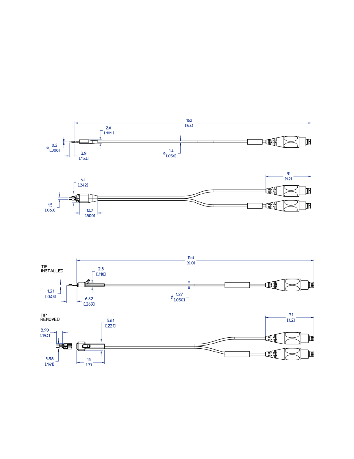
InfiniiMax III Probe Heads Dimensions
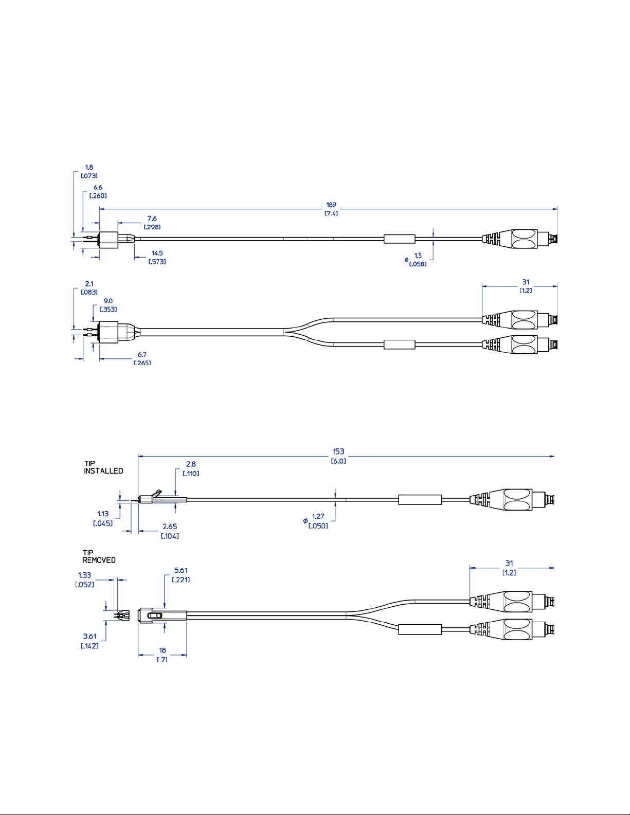
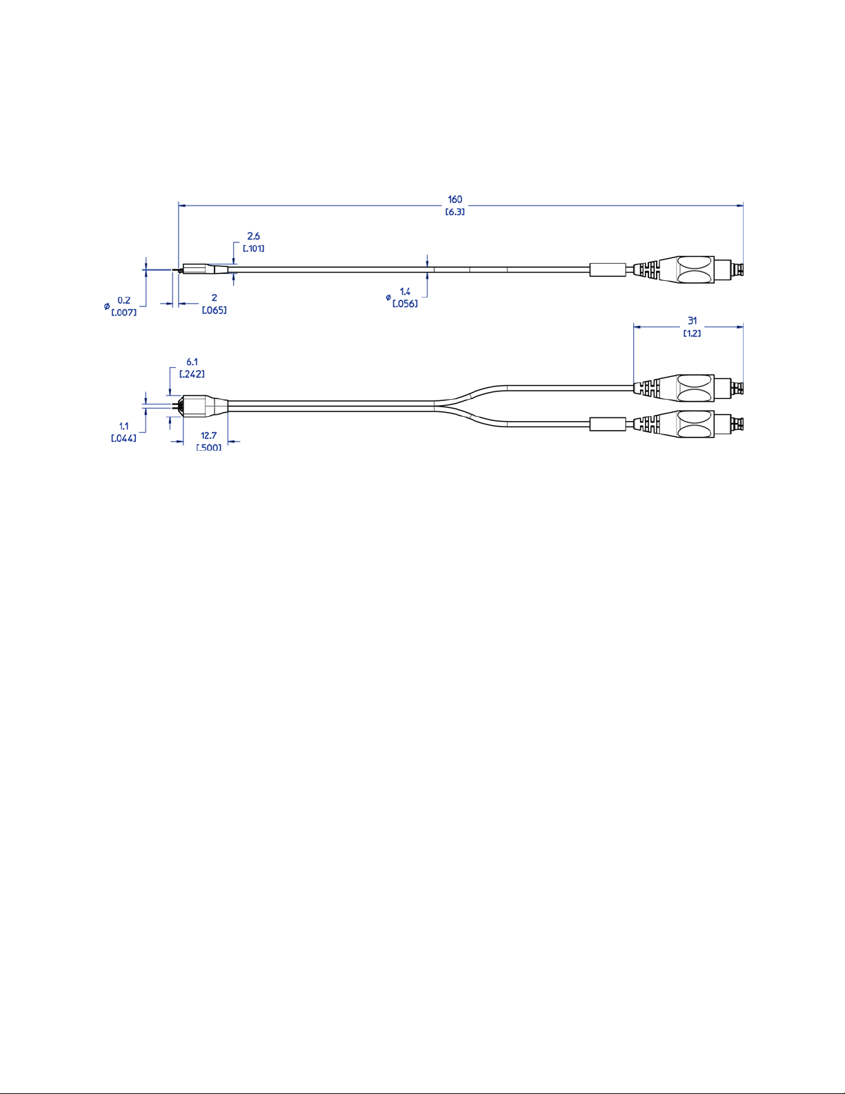
All dimensions included in this section are in millimeters [inches].
N2836A InfiniiMax III Solder-in Head Dimensions
Performance Specifications / Characteristics 4
N2838A InfiniiMax III PCB ZIF Tip with N5439A ZIF Head Dimensions
InfiniiMax III Series Probes User’s Guide 65
Page 66
4 Performance Specifications / Characteristics
N2848A InfiniiMax III QuickTIp Tip with N2849A QuickTip Head Dimensions
N5440A/N5447A InfiniiMax III Ceramic ZIF Tip with N5439A ZIF Head Dimensions
66 InfiniiMax III Series Probes User’s Guide
Page 67
Performance Specifications / Characteristics 4
N5441A InfiniiMax III Solder-in Head Dimensions
InfiniiMax III Series Probes User’s Guide 67
Page 68

4 Performance Specifications / Characteristics
68 InfiniiMax III Series Probes User’s Guide
Page 69
Keysight InfiniiMax III Series Probes
User’s Guide
5 Calibration / Deskew
Procedure
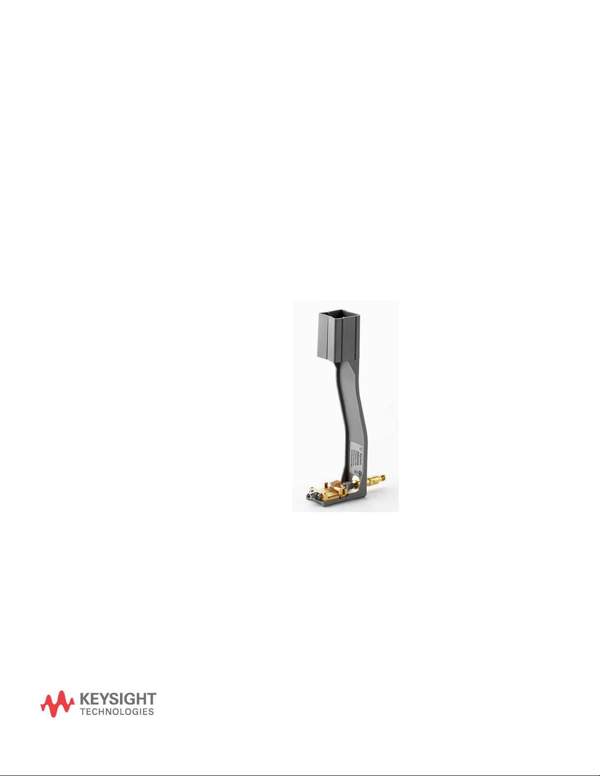
To perform a calibration/deskew for the InfiniiMax III Probing system, you will be using the
N5443A Calibration/Deskew Fixture.
This fixture enables you to not only calibrate / deskew your InfiniiMax III probe, but it also
ensures you properly position the probe amplifier during the procedure via the plastic
holder. You can remove the plastic holder from the fixture by removing the four screws on
the bottom side of the holder if you prefer.
69
Page 70
5 Calibration / Deskew Procedure
Procedure
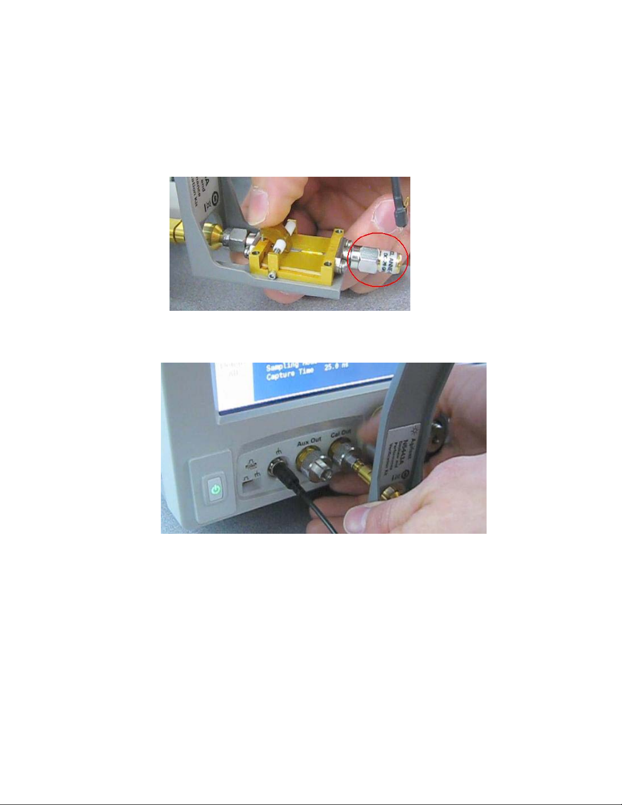
1 To perform a DC calibration / calibrated skew, make sure the 50 ohm terminator (included
with N5443A) is connected to the fixture as shown below.
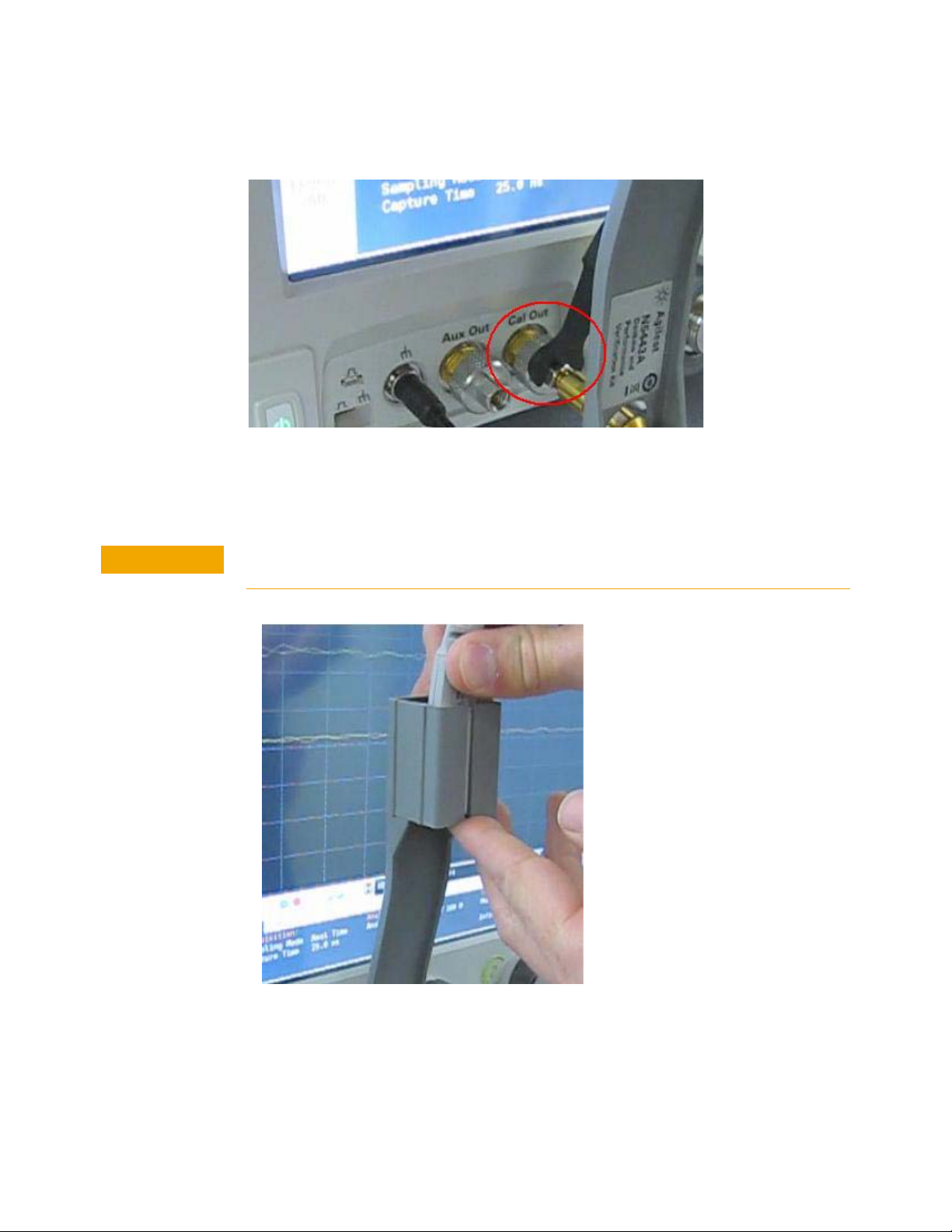
2 Hold the N5443A upright and connect the fixture to the Cal Out on the oscilloscope. Turn
the nut on the Cal Out counter-clockwise to tighten.
3 While holding the fixture upright with one hand, use an 8 in. lbs. torque wrench to fully
tighten the connector as shown on the next page.
70 InfiniiMax III Series Probes User’s Guide
Page 71
Calibration / Deskew Procedure 5
CAUTION
4 Connect the probe amplifier to one of the channel inputs on the oscilloscope.
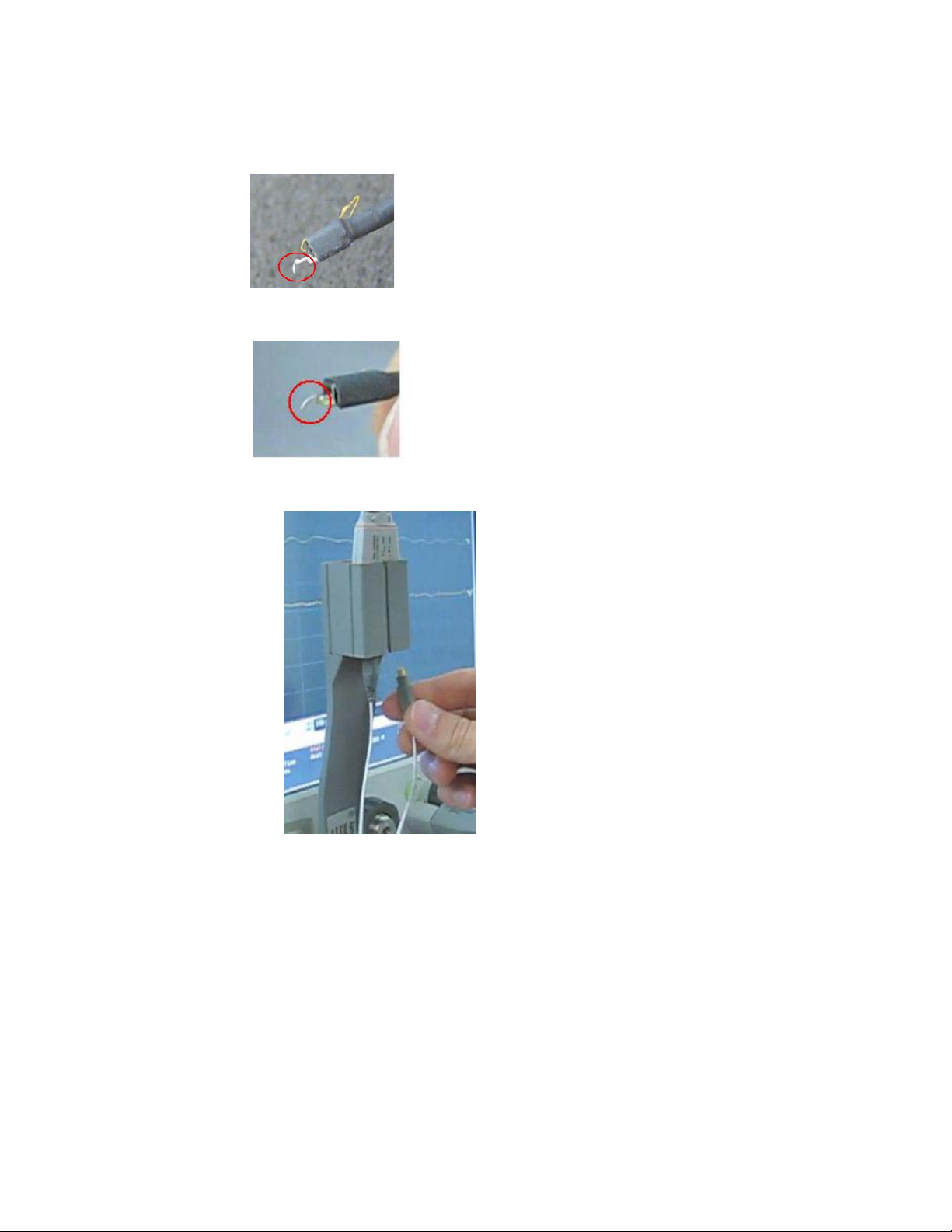
5 Insert the amplifier into the top of the fixture holder. The amplifier can slide up and down in
the holder to adjust the probe head position.
Always wear an ESD wrist strap when working with active probes. Not doing so can result in
the probe becoming permanently damaged.
6 Before connecting to the N5443A fixture, form the N5439A probe head ZIF tip wires as
shown below (if using the ZIF tip for the calibration / deskew). If you are using the browser
probe head then you do not need to adjust the shape of the tips.
InfiniiMax III Series Probes User’s Guide 71
Page 72
5 Calibration / Deskew Procedure
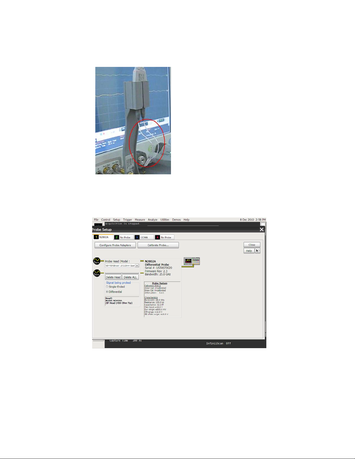
Form the wires as shown below if using the N5441A solder-in probe head.
7 Connect your probe head to the amplifier.
8 Position the probe head wires (if you are using the ZIF or Solder-in probe heads) so they
curl towards the scope as shown below.
72 InfiniiMax III Series Probes User’s Guide
Page 73
Calibration / Deskew Procedure 5
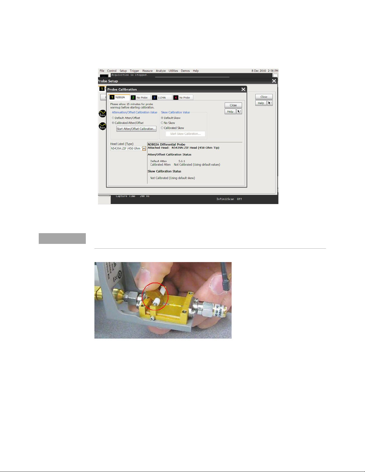
9 Press the Menu button on the probe amplifier to bring up the Probe Setup dialog box on
the oscilloscope.
10 In the Probe Setup dialog box, click on the Calibrate Probe ... button. This will open the
Probe Calibration dialog box.
11 In the Probe Calibration dialog box, select the probe head you are using in the Head Label
(Type) field, select the Calibrated Atten/Offset radio button, and press the Start
Atten/Offset Calibration... button.
InfiniiMax III Series Probes User’s Guide 73
Page 74
5 Calibration / Deskew Procedure
NOTE
12 A dialog box will then open that tells you how to connect the probe head to the
calibration/deskew fixture.
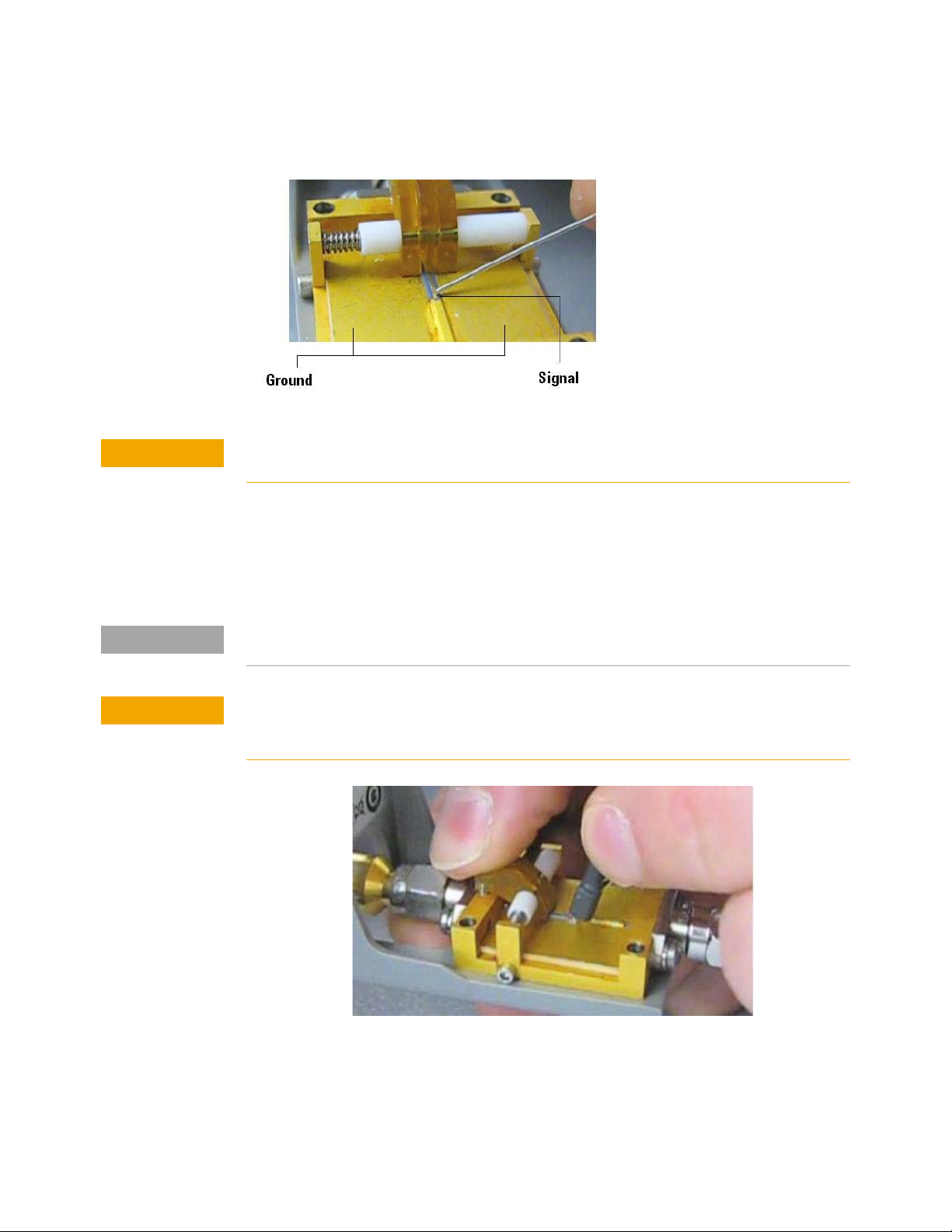
The fixture has three spring-loaded fingers (shown below) that clamp probe head wires to
the fixture if you are using the ZIF probe head or the Solder-in probe head.
13 On the fixture, the center gold trace is signal and the large plates on either side are both
ground as shown below.
74 InfiniiMax III Series Probes User’s Guide
Page 75
Calibration / Deskew Procedure 5
CAUTION
NOTE
CAUTION
Never solder a probe tip to the thickfilm gold. The gold will immediately dissolve into the
solder and disappear.
14 Follow the instructions on the oscilloscope to clamp the wires to either the signal or
ground. When connecting the probe wires to the fixture, press down on the spring-loaded
fingers described in Step 12 and insert the probe wires. You can check that the wires are
connected correctly by pressing the autoscale button on the front panel and checking that
you have a stable step on screen (note that pressing autoscale will close the Probe
Calibration dialog box).
People tend to have their own preference for this step in terms of the angle to view and insert the probe
wires under the spring-loaded fingers. Try different angles to determine your optimum method.
When connecting the probe head to the fixture, do not press down with much force or you
could snap off the fixture from the Cal Out connection. Light contact is all that is needed for
the calibration.
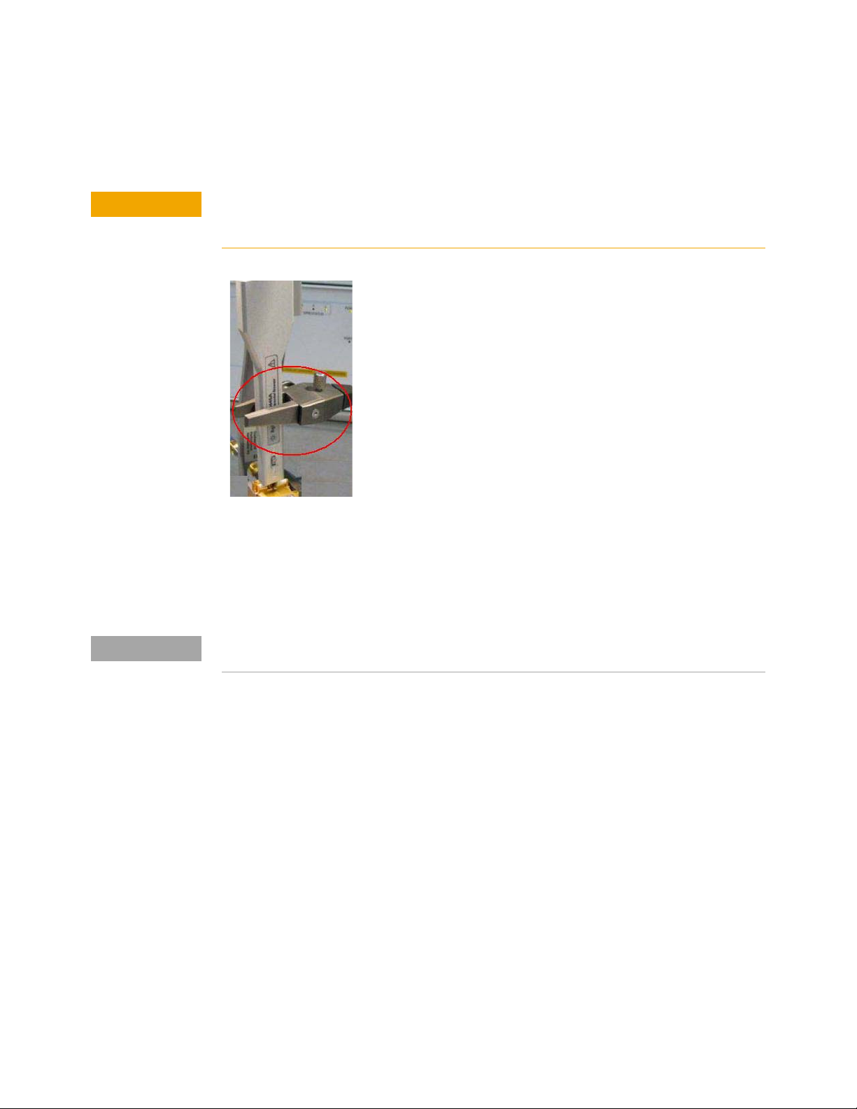
15 If you are using the browser probe head, it is recommended that you use the N2787A 3D
Probe Positioner to hold the browser in place (as shown below). The browser uses
spring-loaded tips so you do not need much force to get a solid contact. You can check
that the tips are connected correctly by pressing the autoscale button on the front panel
InfiniiMax III Series Probes User’s Guide 75
Page 76
5 Calibration / Deskew Procedure
CAUTION
NOTE
and checking that you have a stable step on screen (note that pressing autoscale will close
the Probe Calibration dialog box).
When connecting the probe head to the fixture, do not press down with much force or you
could snap off the fixture from the Cal Out connection. Light contact is all that is needed for
the calibration.
16 With the probe head correctly connected to the fixture, press OK in the dialog box on the
oscilloscope and wait for the calibration to finish. It will report whether the calibration was
successful or not.
17 Once the calibration has successfully completed, the DC Cal LED on the probe amplifier
will turn green indicating that the particular combination of probe amplifier, probe head,
and oscilloscope channel input has been calibrated.
Any time you use a new probe head type, a new probe amplifier, or a different channel on the
oscilloscope, the DC Cal LED will be amber, indicating that a DC calibration is required.
18 Once the DC vertical calibration has successfully completed, select the Calibrated Skew
radio button from the Probe Calibration dialog box on the oscilloscope. Then press the
Start Skew Calibration... button and follow the on-screen instructions for the skew
calibration.
76 InfiniiMax III Series Probes User’s Guide
Page 77

Keysight InfiniiMax III Series Probes
CAUTION
User’s Guide
6 Performance Verification
Bandwidth Performance Verification 78
DC Input Resistance Performance Verification 96
Performance Test Record 99
This chapter describes the equipment and procedures needed to verify the performance of
InfiniiMax III probes. Due to the very high frequency of the InfiniiMax III probing system, it is
important to carefully adhere to the techniques and procedures described in this chapter
to accurately measure the performance.
It is also important to note that the performance measured here is of the probe by itself.
Keysight high performance real-time scopes (and sampling scopes under certain
conditions) will apply probe correction that will further enhance the performance of the
probes.
Electrostatic discharge (ESD) can quickly and imperceptibly damage or destroy high
performance probes, resulting in costly repairs. Always wear a wrist strap when handling
probe components and insure that cables are discharged before being connected.
77
Page 78

6 Performance Verification
Bandwidth Performance Verification
This section documents the bandwidth performance of the N2803A InfiniiMax III Probe
Amplifier with the N5439A ZIF probe head and N5440A ceramic ZIF tip or with the N5445A
browser probe head.
Keysight recommends a test interval of one year or 2000 hours of operation.
Equipment Needed
• Keysight 2 port E8361A/C Vector Network Analyzer:
• Or equivalent VNA that covers at least a 50 MHz to 34 GHz range. This procedure is
written assuming the E8361A/C PNA. If a different VNA is used, references that are
specific to the PNA will need to be modified.
• Needs proper test port cables and/or adaptors to provide male 2.92 mm connectors
at reference planes. If test port cables are 2.4 mm or 1.85 mm cables, then Keysight
11904A and 11904D adaptors can be used to convert to 2.92 mm male connectors.
• Needs to be capable of using a Touchstone file to de-embed at a port.
• Needs to have bias port for port 1 of the VNA (i.e. has internal bias T’s and a BNC
port that allows bias to be applied to port 1)
• Keysight N5443A Performance Verification Fixture.
• Maury Microwave 8775B2 2.92 mm male broadband load, or other 2.92 mm male load
with similar or better return loss. A high quality 2.92 mm adaptor to a 2.4 mm or
1.85 mm VNA calibration load with required return loss could be used.
• Keysight N5477A Autoprobe II/3.5 mm Adaptor.
• Keysight 1143A Power supply.
• Keysight 5062-1247 outside thread 3.5 mm (male) to 3.5 mm (female) adaptor.
• Keysight N4692A-00F 2.92 mm (female/female) ECal module. Or, other 2.92 mm
calibration kit that can calibrate to the 2.92 mm male connectors at the test ports.
• BNC 50 ohm male terminator or equivalent; not a critical part. For example, Pomona
number 3840-50 or 4119-50.
• InfiniiMax III Probe Head. Either the N5439A ZIF probe head with the N5440A ceramic
ZIF probe tip or the N5445A browser probe head.
78 InfiniiMax III Series Probes User’s Guide
Page 79
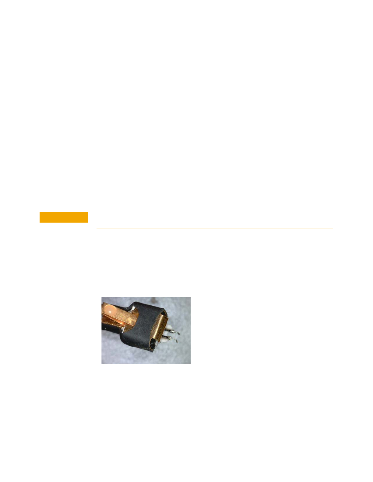
VNA Setup
CAUTION
•Power level: –6 dBm.
• Sweep: Log Frequency 50 MHz to 34 GHz, 284 points (100 pts/decade).
•IF BW: 1 kHz.
• Test port cables and adaptors (if needed) to provide male 2.92 mm connectors at
• Install the BNC 50 ohm terminator to the bias input for port 1 of the VNA (on the rear
• Clear all traces from display, then select S12 to display.
• Set scale for S12 to 3 dB/div, with reference level to 0 dB and reference position to 5
Procedure
1 Calibrate the PNA to the two male 2.92 mm connectors (connectors can be seen in
Figure 62) using the N4692A-00F ECal module (or equivalent 2.92 mm cal kit).
Performance Verification 6
measurement planes.
panel of E8361 PNA). This provides a DC 50 ohm termination for the probe amp output.
divisions.
As with all precision connector interfaces, make sure to torque all connections using the
proper torque wrench!
2 Prepare the N5439A ZIF probe head for connection to the PV fixture as shown in Figure 61.
a
Install a N5440A ceramic ZIF tip into the N5439A ZIF probe head. Make sure
it is fully inserted.
b Bend the tip wires down at their halfway point using fine tweezers.
c Slightly spread the tips wires to better match the spacing needed for the PV
fixture.
Figure 61 N5439A ZIF Probe Head
3 Connect the 1250-1749 adapter and N5443A PV fixture assembly to the calibrated ports of
the PNA as shown in Figure 62. A small bench vise is useful to hold PV fixture steady.
InfiniiMax III Series Probes User’s Guide 79
Page 80
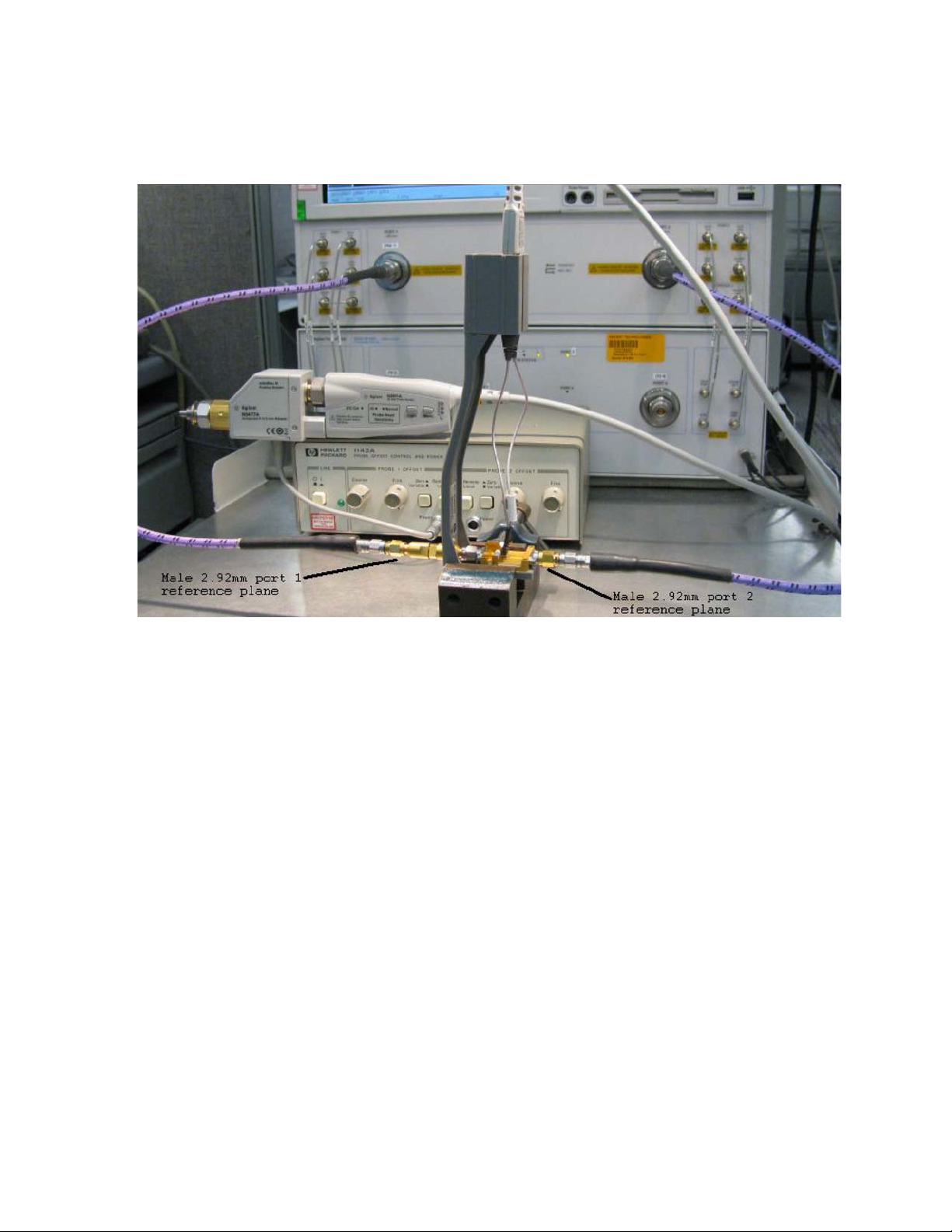
6 Performance Verification
Figure 62 Setup for measuring “Vin” of probe
4 Connect the N5477A AutoProbe II adaptor to the 1143A power supply and turn on the
power supply.
a
Make sure the probe offset control button on the 1143A is set to “Zero” so no
probe offset is applied.
b The 5062_1247 adapter should be attached to the N5477A and properly
torqued.
5 Connect the probe amp pod end to the N5477A and torque connector.
6 Connect the probe to the N5443A PV fixture:
a
Probe amp with ZIF probe head is inserted into the PV holder far enough
that the tip wires can easily reach the pinchers on the PV fixture.
b Form the coax cables so that the tip wires are close to the pincher points
before trying to connect the tip wires. The connectors between the probe
head and the probe amp can be rotated to align the probe tip properly to the
pinchers. Since the center trace of the PV fixture is above the ground plane,
the probe head should be tipped slightly so the tip wires touch the center
trace and ground plane at the same time.
c Depress the actuators on the pinchers and carefully insert one wire under
the center pincher and the other wire under one of the side pinchers. Either
polarity of the probe can be tested and will yield the same results (but
80 InfiniiMax III Series Probes User’s Guide
Page 81
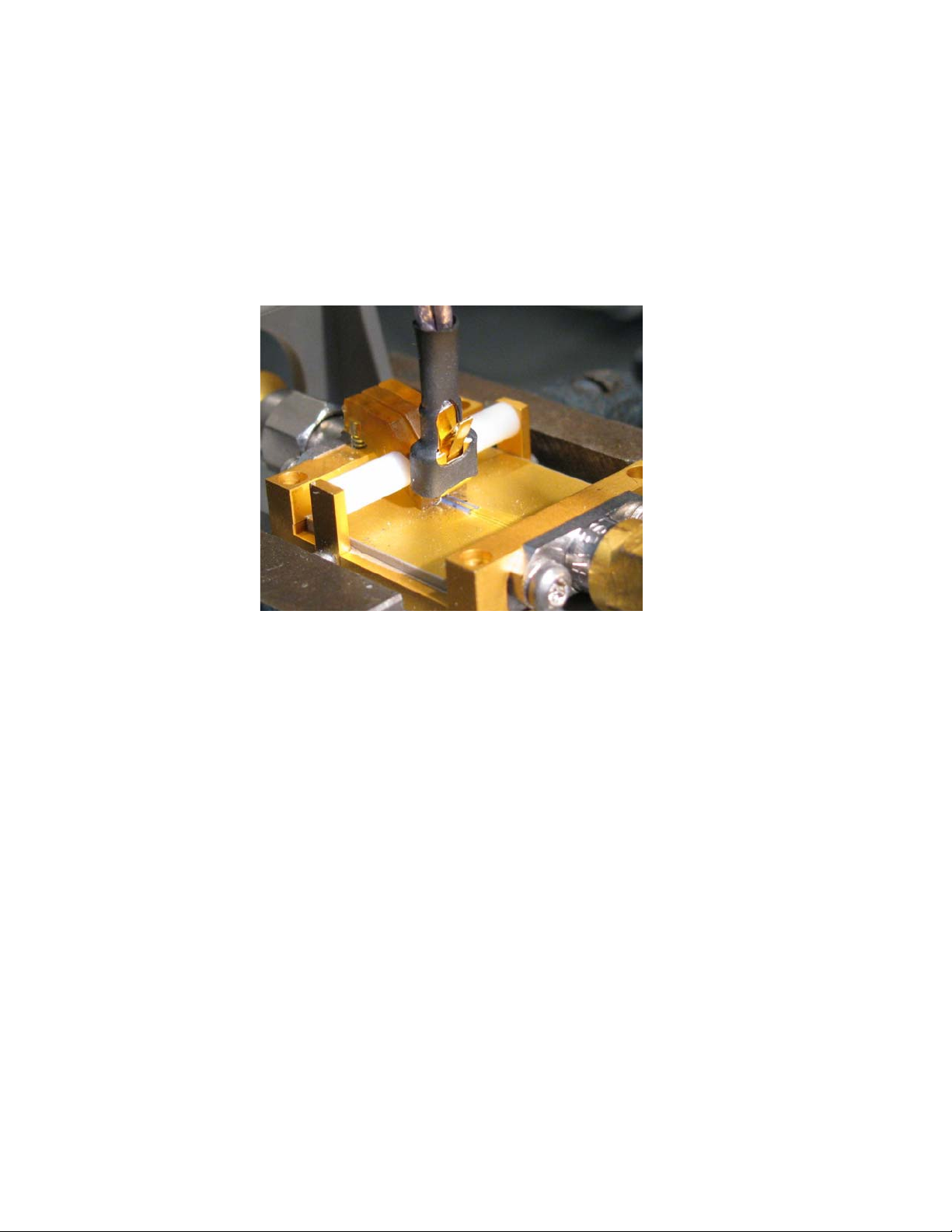
Performance Verification 6
opposite phase) if the probe is working properly. Figure 63 shows a close up
of the tip wires positioned under the pinchers.
d Ideally the probe head should not be angled toward the port 2 side of the PV
fixture, but a slight angle of 5 degrees is acceptable. If angled too much, the
measured BW of the probe will be degraded due to coupling from the trace
to the probe tip.
Figure 63 Close-up of tip wires positioned under pinchers
7 Install the proper file to de-embed the 1250-1749 adapter and the output side of the
N5443A (i.e. the path from the male 2.92 mm connector to the probe point of the N5443A)
from port 1 of the VNA.
a
Create a Touchstone file for the 1250-1749 and N5443A PV fixture by
cutting and pasting the text in “Touchstone File (1250-1749 & N5443A)" on
page 88. Name the file Adaptor_1250_1749___OutputSideOfFixture_N5443A.s2p.
b On the VNA, go to menu “Calibration/Fixturing Selections/2 Port
De-embedding” and select Port 1.
c Set S2P file selection to the file saved in step a.
d Check the “Enable De-embedding”.
e Under “Calibration” menu, select “Fixturing ON/off” to turn on
de-embedding.
8 Trigger VNA to perform a single sweep. a. Press “Trigger” under Channel Setup, and then
the green soft-key for “Single”. Display should look like Figure 64. If it looks noticeably
different, the probe tip wires may not be making contact under the pinchers.
9 Under “Trace/Math/Memory” select “Data->Memory”. This will save the de-embedded
input voltage trace into the memory.
InfiniiMax III Series Probes User’s Guide 81
Page 82
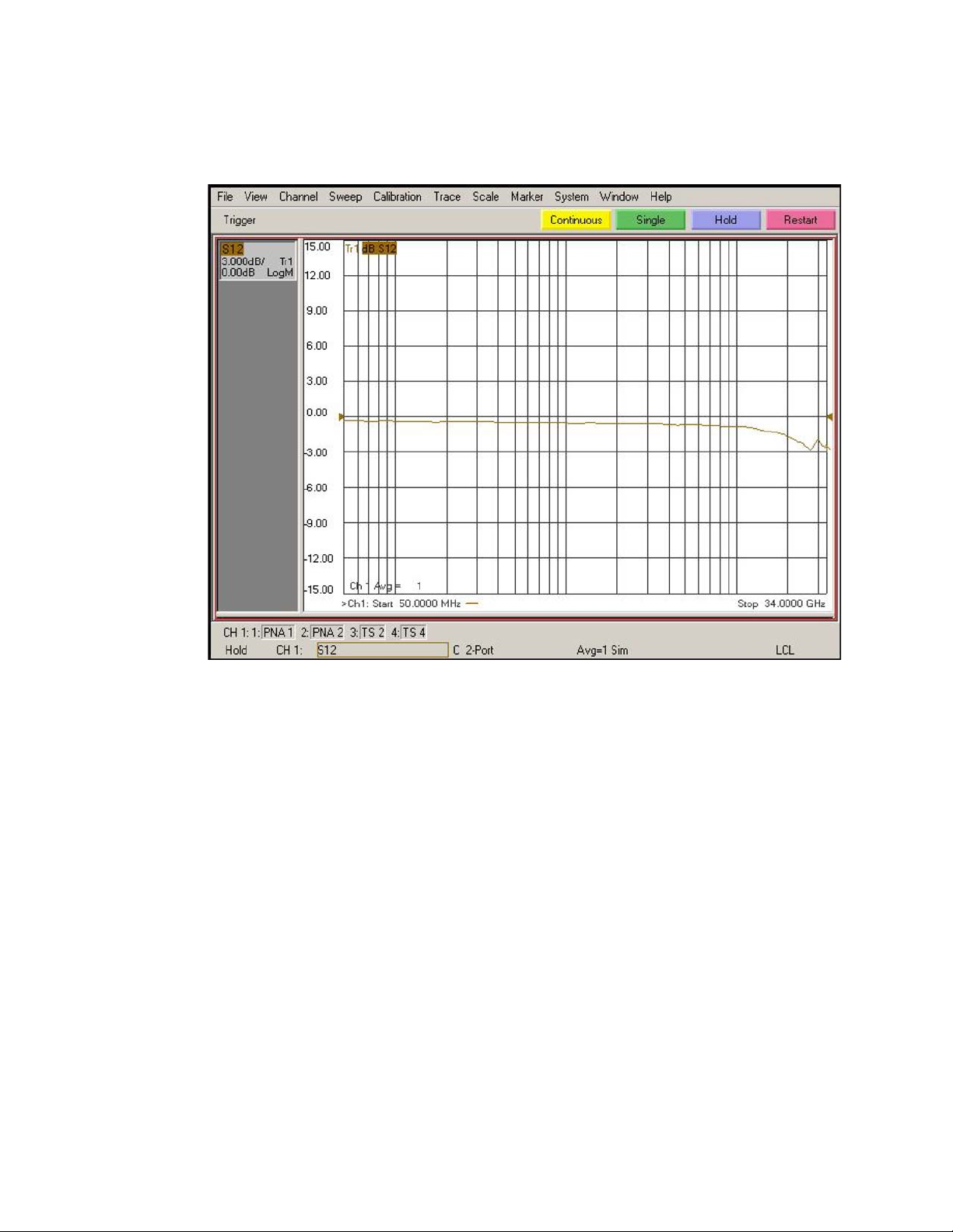
6 Performance Verification
Figure 64 De-embedded “Vin” trace
10 Now move the 2.92 mm male test port 1 connector to the 5062_1247 adapter and N5477A
Autoprobe II adapter assembly. Connect the Maury Microwave 8775B2 2.92 mm male
broadband load to the 1250_1749 adaptor and N5443A PV fixture assembly. This new
setup is shown in Figure 65. Torque all connections.
11 Install the proper file to de-embed the 5062_1247 adapter and N5477A adapter from port
1 of the VNA.
a
Create a Touchstone file for the 5062-1247 and N5477A by cutting and
pasting the text in “Touchstone File (5062-1247 & N5477A)" on page 92.
Name the file Adapter_5062_1247___Adapter_N5477A.s2p.
b Go to menu “Calibration/Fixturing Selections/2 Port De-embedding” and
select Port 1.
c Set S2P file selection to the file saved in step a.
d Make sure the “Enable De-embedding” box is still checked.
e Under “Calibration” menu, make sure “Fixturing ON/off” is still checked so
file is being used for de-embedding.
82 InfiniiMax III Series Probes User’s Guide
Page 83
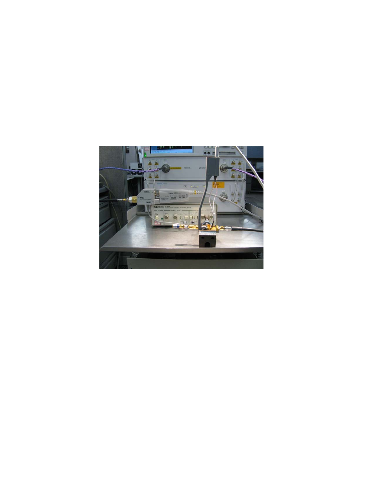
12 Trigger VNA to perform a single sweep.
a
Press “Trigger” under Channel Setup, and then the green soft-key for
“Single”.
b Under “Scale” menu, adjust the reference level until the 50 MHz point (left
side of the screen) is at center screen. Reference level should be
approximately -15.3 dB, but can vary a few tenths of a dB either way.
c Display should look like Figure 66. If it looks noticeably different, the probe
tip wires may not be making contact under the pinchers.
Performance Verification 6
Figure 65 Setup to measure “Vout” of probe
InfiniiMax III Series Probes User’s Guide 83
Page 84
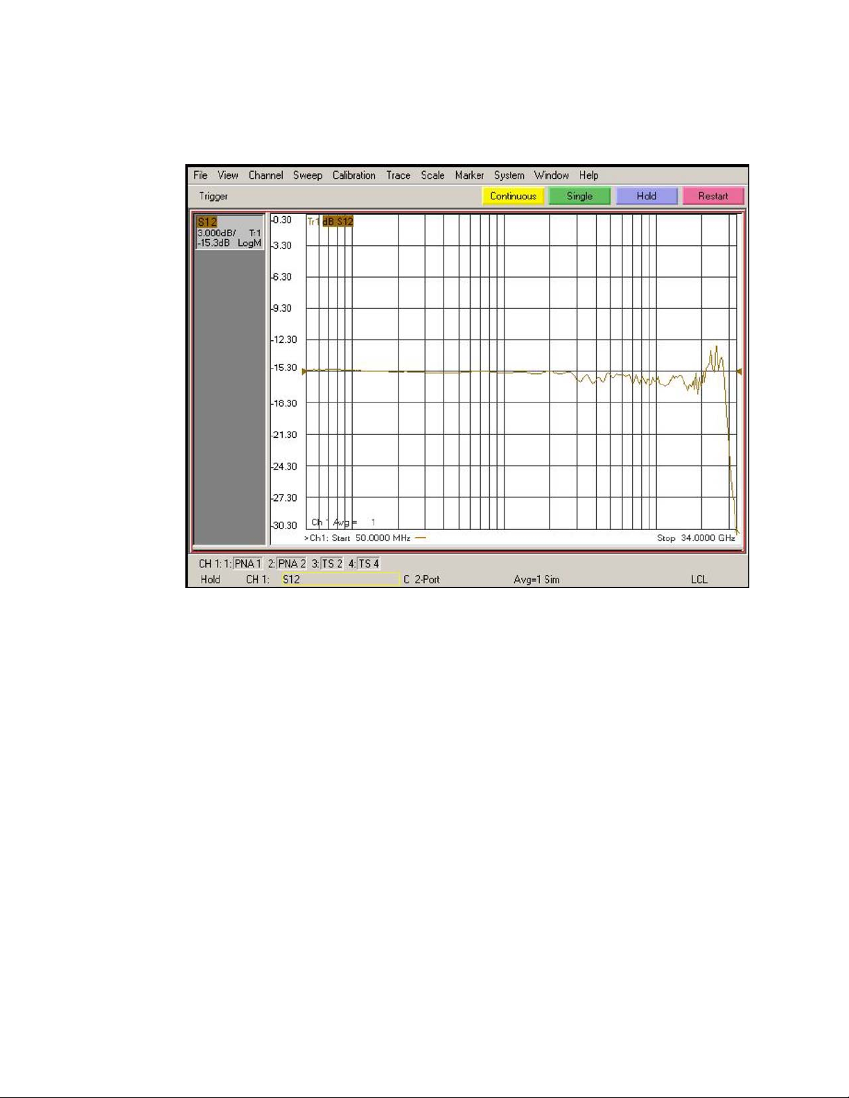
6 Performance Verification
Figure 66 De-embedded “Vout” trace
13 Under menu “Trace/Math/Memory” select “Data/Memory” in the “Data Math” box.
This will divide the current trace (de-embedded vout trace) by the memory
a
trace (de-embedded vin trace) and therefore show the voltage transfer
function of the probe or “vout/vin”.
b Again, adjust the “Reference Level” in the scale menu so the 50MHz point is
at center screen. The display should look like Figure 67.
c Turn on a marker and adjust it to where the trace crosses 3 dB below the
50 MHz point (which is 1 division below center screen since screen is set to
3 dB/div).
d Verify that the BW is ≥ 26 GHz for the N5440A ceramic ZIF tip, N5439A ZIF
probe head, and N2803A 30 GHz probe amp combination.
84 InfiniiMax III Series Probes User’s Guide
Page 85
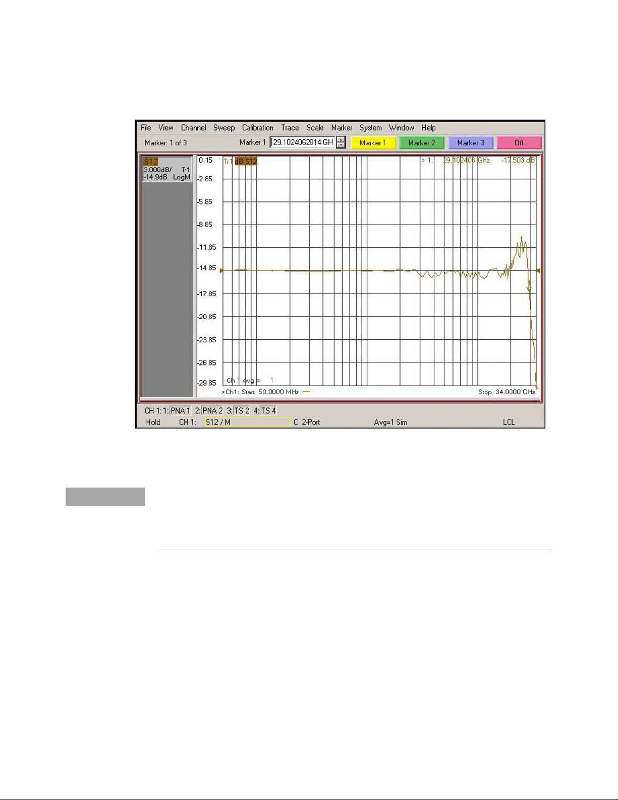
Performance Verification 6
NOTE
Figure 67 De-embedded “Vout/Vin” response of the probe
You only need to perform the Bandwidth Performance Verification test with the ZIF tip as described
above. If the probe passes with the ZIF probe head then it will pass with the browser probe head as well.
You are not required to test the bandwidth specification with both probe heads. If you have the choice
between using the ZIF probe head or the browser, Keysight suggests using the ZIF probe head because
measurements are more repeatable with it and it is easier to make a proper connection.
To measure the performance of the N5445A Browser with the N2803A probe amp, the
same procedure as described above is used except the browser is held in position with a
probe positioner. This setup is shown in Figure 69 and Figure 69 using the Keysight
N2787A 3D Probe Positioner.
1 Tilt the browser slightly so the two tips touch the center trace and the ground plane on the
PV fixture at about the same time.
2 Probe the halfway point between the where the pinchers are and where the microstrip
transitions into the rectangular coax line.
3 Set the span of the browser to the minimum possible as should in this picture:
InfiniiMax III Series Probes User’s Guide 85
Page 86
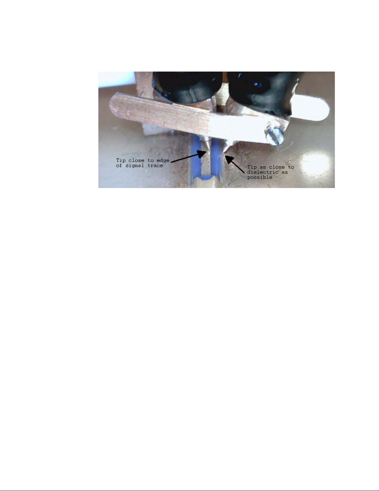
6 Performance Verification
Figure 68 Probe Tips on Microstrip
86 InfiniiMax III Series Probes User’s Guide
Page 87
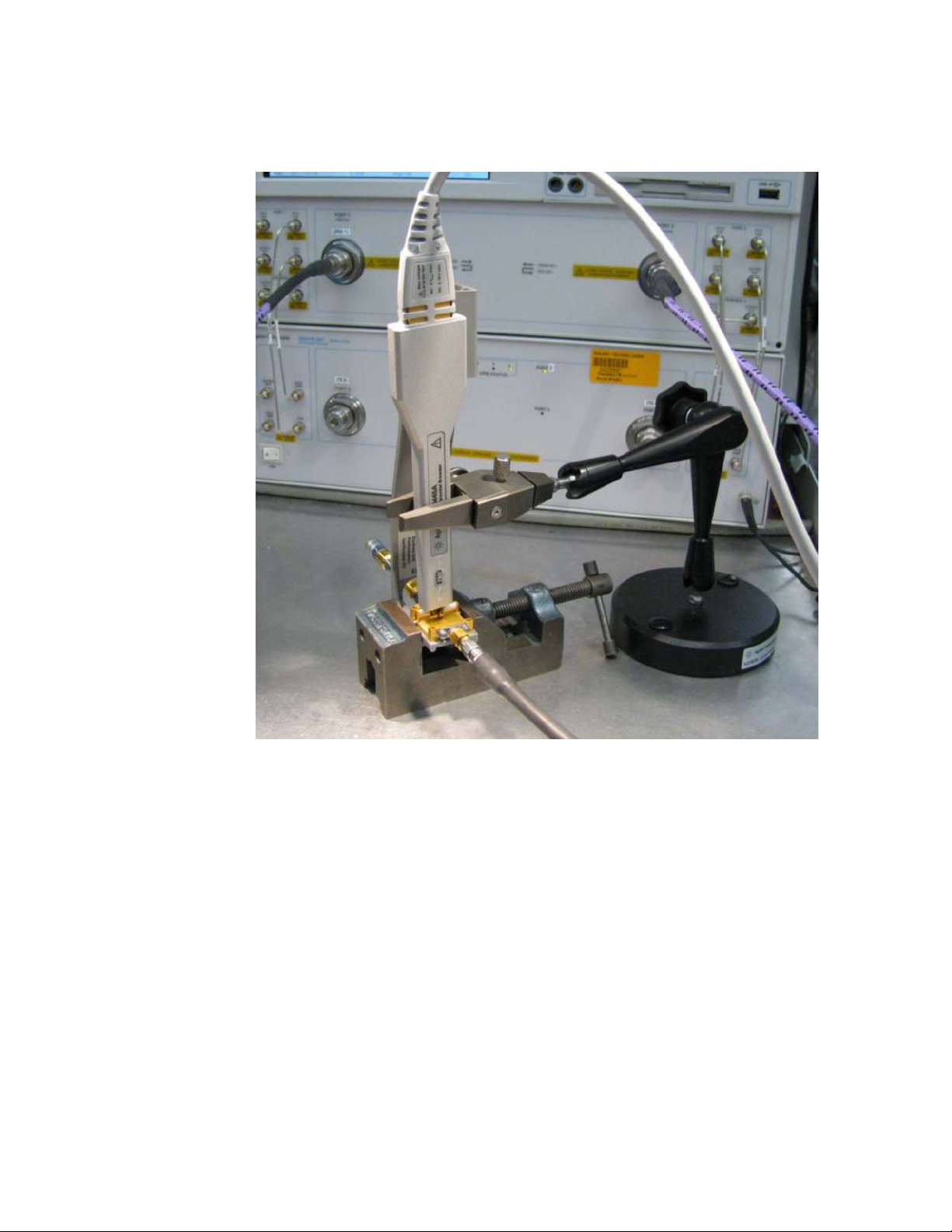
Performance Verification 6
Figure 69 N2787A 3D Probe Positioner used to measure the N5445A browser with the
N2803A amp
InfiniiMax III Series Probes User’s Guide 87
Page 88

6 Performance Verification
NOTE
Touchstone File (1250-1749 & N5443A)
Cut and paste the following text and save in a text file named
Adapter_1250_1749___OutputSideOfFixture_N5443A.s2p. This file is used in Step 7 on page 81.
You’ll also find the following data on the Adobe AIR version of the Probe Resource Center (PRC).
Copying this data from the PRC is the simplest most reliable method to get the data. To download the
PRC, visit http://www.Keysight.com/find/PRC.
! freq S11 S21 S12 S22
!Port 1=female 3.5mm connector of 1250-1749 adaptor, Port 2=probe point on N5443A fixture
# Hz S DB R 50
50000000.000000 -49.528411 110.869328 -0.026318 -4.180881 -0.025870 -4.223772 -67.754661 -176.153454
51165694.067857 -49.988587 91.181375 -0.025517 -4.280433 -0.024720 -4.324675 -68.880923 -164.662475
52358564.988911 -50.522661 71.165730 -0.024697 -4.382306 -0.023543 -4.427929 -70.190588 -152.193533
53579246.361093 -51.148132 50.755093 -0.023858 -4.486555 -0.022339 -4.533591 -71.710672 -138.296498
54828386.553961 -51.883012 29.852775 -0.023000 -4.593234 -0.021107 -4.641716 -73.455393 -122.229302
56106649.053084 -52.745137 8.328609 -0.022122 -4.702400 -0.019846 -4.752362 -75.383422 -102.800368
57414712.812455 -53.751090 -13.985221 -0.021223 -4.814111 -0.018557 -4.865588 -77.285484 -78.453735
58753272.615119 -54.914477 -37.296089 -0.020304 -4.928426 -0.017237 -4.981454 -78.641246 -48.710849
60123039.442212 -56.136285 -60.059373 -0.019410 -5.044783 -0.015920 -5.098670 -78.505514 -17.996645
61524740.850598 -56.339746 -65.253403 -0.018972 -5.157375 -0.014907 -5.204612 -74.600997 0.238726
62959121.359318 -56.549712 -70.614809 -0.018523 -5.272593 -0.013871 -5.313024 -71.786638 16.619539
64426942.845040 -56.765722 -76.151300 -0.018064 -5.390497 -0.012811 -5.423964 -69.665881 32.555062
65928984.946733 -56.987159 -81.870529 -0.017595 -5.511150 -0.011726 -5.537491 -68.056466 48.587163
67466045.479778 -57.213226 -87.779882 -0.017115 -5.634616 -0.010616 -5.653665 -66.866526 65.023732
69038940.859729 -57.442930 -93.886209 -0.016623 -5.760962 -0.009481 -5.772548 -66.050126 82.119449
70648506.535956 -57.624590 -110.396155 -0.016195 -5.894832 -0.009445 -5.897344 -64.822182 90.200098
72295597.435395 -57.551220 -142.499775 -0.015869 -6.038769 -0.011116 -6.029813 -62.891316 82.809542
73981088.416647 -57.272309 -174.184620 -0.015537 -6.186061 -0.012827 -6.165369 -61.314332 74.543748
75705874.734666 -56.913609 155.103108 -0.015196 -6.336786 -0.014577 -6.304085 -59.987656 65.638030
77470872.516269 -56.615036 125.361237 -0.014847 -6.491025 -0.016368 -6.446035 -58.847549 56.200571
79277019.246748 -56.489319 96.190629 -0.014491 -6.648860 -0.018202 -6.591294 -57.851655 46.281987
81125274.267814 -56.086810 77.082571 -0.015125 -6.803245 -0.019025 -6.749358 -57.369635 49.668006
83016619.287160 -55.464039 64.084902 -0.016432 -6.956544 -0.019176 -6.917300 -57.199270 61.953448
84952058.899892 -54.917900 50.564549 -0.017770 -7.113416 -0.019329 -7.089158 -57.075871 74.341353
86932621.122130 -54.439335 36.470021 -0.019138 -7.273947 -0.019487 -7.265023 -57.007441 86.897368
88959357.937037 -54.018288 21.746324 -0.020539 -7.438220 -0.019648 -7.444988 -57.001200 99.698955
91033345.853589 -54.097863 14.550734 -0.021520 -7.608109 -0.020285 -7.619545 -56.504223 102.747003
93155686.478363 -54.688270 15.600999 -0.022057 -7.783797 -0.021424 -7.788273 -55.536632 95.350174
95327507.100664 -55.335875 16.745463 -0.022606 -7.963581 -0.022589 -7.960934 -54.662417 87.625100
97549961.291281 -56.051127 18.007724 -0.023168 -8.147556 -0.023782 -8.137620 -53.867407 79.587653
99824229.515220 -56.847547 19.421327 -0.023744 -8.335819 -0.025002 -8.318424 -53.140655 71.244030
102151519.758706 -57.028409 32.229328 -0.024811 -8.518103 -0.025270 -8.526257 -53.229937 71.824660
104533068.170813 -57.203696 45.767193 -0.025943 -8.703769 -0.025461 -8.740842 -53.390484 73.175172
106970139.720046 -57.452641 59.100435 -0.027102 -8.893763 -0.025657 -8.960430 -53.558351 74.544470
109464028.866236 -57.799354 72.247228 -0.028288 -9.088187 -0.025857 -9.185138 -53.734081 75.931667
112016060.248099 -58.205431 76.407713 -0.028945 -9.298506 -0.026957 -9.388528 -53.893471 72.124731
114627589.386818 -58.637120 78.159701 -0.029466 -9.516820 -0.028326 -9.589435 -54.061522 66.848820
117300003.406038 -59.105065 79.877381 -0.029999 -9.740223 -0.029727 -9.795026 -54.247548 61.492888
120034721.768639 -59.584054 81.490201 -0.030537 -9.968856 -0.031146 -10.005562 -54.448452 56.117498
122833197.030691 -57.847096 78.713336 -0.030505 -10.204469 -0.031384 -10.233007 -54.242926 55.717121
125696915.612984 -56.373050 75.635986 -0.030472 -10.445575 -0.031627 -10.465755 -54.037670 55.307462
128627398.590544 -55.090007 72.338796 -0.030439 -10.692303 -0.031876 -10.703929 -53.832682 54.888298
131626202.500562 -54.306379 66.932129 -0.030205 -10.948451 -0.031570 -10.953764 -53.494817 54.988088
134694920.169152 -53.880297 59.647516 -0.029793 -11.213741 -0.030773 -11.214700 -53.052945 55.558900
137835181.557386 -53.486272 52.104536 -0.029372 -11.485216 -0.029957 -11.481720 -52.622790 56.157336
141048654.627056 -53.508282 45.730461 -0.030159 -11.752986 -0.030107 -11.751715 -52.284361 56.421252
144337046.226616 -54.420700 42.364200 -0.033536 -12.005802 -0.032342 -12.021139 -52.117964 55.931890
147702102.997784 -55.470568 39.211352 -0.036994 -12.264512 -0.034630 -12.296845 -51.951089 55.430858
151145612.303275 -55.576811 37.842963 -0.039670 -12.539287 -0.036049 -12.583748 -51.944456 54.446241
154669403.176167 -53.732676 40.105390 -0.040639 -12.841065 -0.035607 -12.887130 -52.278075 52.497820
158275347.291397 -52.178102 42.969822 -0.041630 -13.149878 -0.035156 -13.197584 -52.635093 50.550437
161965359.959910 -52.004259 45.986266 -0.041770 -13.470541 -0.034641 -13.513759 -52.766109 50.989381
165741401.145982 -53.013032 48.920340 -0.041128 -13.802856 -0.034066 -13.835944 -52.680124 53.568723
169605476.508267 -54.185614 51.938022 -0.040471 -14.142918 -0.033479 -14.165639 -52.594837 56.183902
173559638.465103 -53.353535 46.144495 -0.039591 -14.466058 -0.034106 -14.495652 -52.681223 53.054380
177605987.284668 -52.395549 39.070167 -0.038666 -14.793912 -0.034887 -14.832523 -52.797494 49.218907
181746672.200541 -52.169589 35.688968 -0.038595 -15.133923 -0.035919 -15.178503 -53.030384 48.315967
185983892.553281 -52.903697 37.808367 -0.039749 -15.488188 -0.037303 -15.534312 -53.432713 51.562899
190319898.958608 -53.671016 40.107673 -0.040862 -15.851057 -0.038670 -15.897833 -53.787995 54.424805
194756994.502833 -53.801795 43.465778 -0.041123 -16.226810 -0.039438 -16.262335 -53.156789 52.243875
199297535.966146 -53.943086 46.823120 -0.041390 -16.611323 -0.040225 -16.635334 -52.557852 50.013514
88 InfiniiMax III Series Probes User’s Guide
Page 89

203943935.074433 -53.374619 45.618787 -0.044122 -16.994561 -0.041601 -17.016611 -52.209576 52.395133
208698659.780268 -52.713418 43.564007 -0.047367 -17.384868 -0.043113 -17.406702 -51.910498 55.677837
213564235.573780 -53.477228 35.859633 -0.049667 -17.770211 -0.046242 -17.803783 -51.477695 53.799018
218543246.824077 -55.032566 26.702114 -0.051641 -18.159282 -0.050036 -18.209336 -51.013276 49.886314
223638338.151939 -53.869091 26.218432 -0.052370 -18.572260 -0.051093 -18.629032 -51.239963 47.730420
228852215.834522 -51.902344 30.275653 -0.052588 -19.000945 -0.051017 -19.060434 -51.778596 46.370604
234187649.242808 -51.933827 29.735652 -0.051672 -19.458329 -0.050622 -19.511235 -52.618817 43.686630
239647472.312564 -52.501771 27.821456 -0.050415 -19.931623 -0.050130 -19.975167 -53.656204 40.914797
245234585.049599 -51.831039 34.835393 -0.052075 -20.398897 -0.050775 -20.408282 -54.529939 34.582488
250951955.070115 -51.206936 39.614303 -0.053717 -20.877562 -0.050675 -20.855888 -54.904078 27.538703
256802619.176963 -50.965190 28.605202 -0.054066 -21.375945 -0.046274 -21.351120 -52.552449 17.284825
262789684.972659 -50.758459 28.217659 -0.053702 -21.875920 -0.045857 -21.868062 -51.711832 15.564753
268916332.509994 -50.587835 40.516894 -0.052486 -22.375796 -0.050221 -22.408982 -52.202077 23.079380
275185815.981130 -51.754800 32.581293 -0.054937 -22.906560 -0.050202 -22.929332 -52.401581 27.377763
281601465.446084 -52.426237 23.436322 -0.057360 -23.444084 -0.049220 -23.461590 -52.225369 30.372145
288166688.601492 -50.141722 22.093874 -0.057147 -23.964218 -0.048206 -24.027394 -51.161468 31.686174
294884972.590629 -49.853653 30.887087 -0.057999 -24.535771 -0.050035 -24.592002 -51.268626 22.265828
301759885.855612 -49.776989 38.708272 -0.059389 -25.124388 -0.052090 -25.164841 -51.422057 12.143268
308795080.032796 -48.347696 33.823620 -0.061131 -25.692961 -0.051459 -25.752786 -50.227178 13.737775
315994291.892351 -48.485936 29.549305 -0.059722 -26.288759 -0.054400 -26.334640 -49.610356 17.239374
323361345.323065 -48.665429 24.275657 -0.058597 -26.902100 -0.056825 -26.949053 -49.521928 23.486824
330900153.363414 -48.490653 18.844559 -0.058508 -27.532108 -0.057357 -27.600499 -49.949091 29.735275
338614720.279990 -48.115523 23.731233 -0.057500 -28.187494 -0.055355 -28.226210 -50.295079 15.284824
346509143.694381 -47.416900 25.416394 -0.058853 -28.843482 -0.058986 -28.876449 -49.620245 11.560046
354587616.759638 -47.838026 23.437700 -0.061373 -29.502109 -0.060345 -29.544775 -49.384503 7.983506
362854430.387485 -48.753096 20.588112 -0.064328 -30.185369 -0.060547 -30.226722 -49.304935 5.118950
371313975.527454 -48.438196 19.789363 -0.066839 -30.908078 -0.063211 -30.919712 -48.959273 7.111174
379970745.499151 -47.335734 18.341686 -0.067669 -31.598820 -0.062202 -31.629439 -50.947829 8.447970
388829338.378905 -47.288518 18.480970 -0.069668 -32.364173 -0.063655 -32.378360 -49.035406 3.520875
397894459.442048 -47.186291 13.294545 -0.075098 -33.096733 -0.066338 -33.140263 -47.851278 4.310910
407170923.662146 -46.940356 14.281384 -0.073798 -33.866977 -0.066345 -33.855087 -48.397382 2.145757
416663658.268484 -47.171461 14.761701 -0.075883 -34.639733 -0.070645 -34.639129 -48.716178 1.898130
426377705.363190 -46.365553 7.572152 -0.076247 -35.447314 -0.071046 -35.477949 -48.899175 2.468785
436318224.599360 -46.701580 7.151913 -0.076870 -36.265959 -0.071287 -36.319100 -49.620160 -4.118647
446490495.921630 -47.160978 13.689850 -0.075994 -37.111578 -0.072545 -37.175224 -50.397815 -8.680461
456899922.370640 -47.396507 5.107440 -0.077071 -37.989362 -0.073385 -38.033366 -49.671733 -15.929710
467552032.952879 -46.077313 2.865178 -0.082064 -38.861189 -0.075185 -38.898976 -49.133541 -14.551426
478452485.577434 -45.259095 -4.008123 -0.080006 -39.743034 -0.076419 -39.807567 -49.683609 -21.223063
489607070.061218 -45.485801 0.581757 -0.083491 -40.697038 -0.079818 -40.709941 -50.060529 -34.194193
501021711.204246 -46.603526 -10.039365 -0.083755 -41.665129 -0.077315 -41.682717 -48.792928 -16.944997
512702471.936616 -45.029650 -7.000027 -0.081662 -42.639573 -0.084559 -42.668191 -47.488874 -20.655839
524655556.538861 -44.514984 -6.354720 -0.079332 -43.615551 -0.083707 -43.641378 -48.492928 -32.031639
536887313.937376 -44.290770 -6.568840 -0.082138 -44.648013 -0.083945 -44.653837 -48.957638 -36.719941
549404241.076669 -43.504772 -8.685522 -0.083652 -45.691901 -0.084815 -45.691684 -49.515830 -29.325183
562212986.370243 -43.481121 -10.960529 -0.085501 -46.733135 -0.082668 -46.765101 -49.399910 -23.211836
575320353.231926 -43.193036 -11.045160 -0.084422 -47.837255 -0.085212 -47.869091 -48.549704 -24.186062
588733303.689526 -43.579719 -5.409896 -0.088905 -48.969584 -0.085630 -48.973225 -47.693589 -29.030108
602458962.082744 -43.188600 -6.651222 -0.088581 -50.106860 -0.090320 -50.094811 -47.786787 -31.167939
616504618.847291 -42.930989 -6.216016 -0.089156 -51.257875 -0.092166 -51.276355 -47.608082 -38.990988
630877734.387229 -43.378333 -4.283740 -0.093976 -52.437082 -0.089960 -52.477553 -47.686557 -37.227422
645585943.037598 -42.988551 -8.753781 -0.093823 -53.639519 -0.091066 -53.698415 -46.547666 -40.593444
660637057.119418 -42.596030 -12.785888 -0.103544 -54.904243 -0.095545 -54.940053 -47.106751 -48.137651
676039071.089234 -42.679026 -16.442780 -0.100600 -56.176567 -0.092255 -56.223911 -47.286734 -45.912639
691800165.785404 -43.248582 -16.783776 -0.101186 -57.495739 -0.095262 -57.497232 -48.306455 -50.044404
707928712.773379 -42.415380 -19.285387 -0.103842 -58.815086 -0.098396 -58.854555 -47.089721 -60.118742
724433278.792294 -41.987336 -27.097520 -0.102116 -60.184767 -0.100383 -60.223125 -47.381752 -64.403202
741322630.305226 -42.380172 -26.675550 -0.103107 -61.606922 -0.099178 -61.610960 -47.908203 -66.412340
758605738.155530 -42.072895 -29.384976 -0.104426 -63.042400 -0.101633 -63.063497 -47.780003 -67.506873
776291782.331738 -41.656096 -32.657305 -0.107282 -64.497662 -0.106240 -64.506014 -46.469069 -72.198347
794390156.843548 -41.748908 -30.061058 -0.109317 -66.001852 -0.105904 -66.011789 -47.270100 -73.483172
812910474.711483 -41.239790 -29.316570 -0.111042 -67.520247 -0.104695 -67.553979 -46.437563 -75.346862
831862573.072888 -40.820512 -28.868361 -0.110486 -69.092396 -0.106359 -69.109196 -46.689929 -71.382011
851256518.406959 -40.299703 -33.428087 -0.112605 -70.722280 -0.107949 -70.719090 -44.864237 -79.807143
871102611.881596 -40.581509 -33.326230 -0.117064 -72.357940 -0.111254 -72.364310 -45.374639 -83.129710
891411394.824904 -40.118229 -36.220425 -0.117204 -74.035916 -0.111664 -74.040042 -45.840643 -83.576746
912193654.324260 -39.532418 -35.546012 -0.117644 -75.756995 -0.111502 -75.761397 -45.992895 -89.364030
933460428.955917 -39.179015 -40.983687 -0.117874 -77.510221 -0.113750 -77.547756 -47.068488 -100.546539
955223014.648186 -39.364010 -46.292129 -0.118168 -79.321186 -0.116241 -79.345373 -46.697516 -107.536739
977492970.681309 -39.278675 -46.564818 -0.119686 -81.179525 -0.117531 -81.189173 -47.024828 -111.261956
1000282125.827218 -39.194967 -51.270372 -0.123784 -83.060780 -0.122650 -83.091199 -46.955841 -115.956987
1023602584.632427 -38.638711 -50.107386 -0.127481 -84.951909 -0.124243 -84.986961 -45.812369 -116.830342
1047466733.847416 -38.254716 -50.795831 -0.130664 -86.951714 -0.126013 -86.984689 -46.398595 -124.148154
1071887249.005892 -38.159836 -50.090886 -0.129842 -88.962105 -0.122894 -88.985826 -45.298698 -117.918878
1096877101.157453 -38.225707 -53.761634 -0.132812 -91.046094 -0.128113 -91.085312 -45.697061 -122.970507
1122449563.757208 -37.836836 -52.245928 -0.132701 -93.180867 -0.128419 -93.190744 -45.762256 -131.225754
1148618219.716024 -37.144353 -57.251248 -0.140371 -95.308530 -0.133202 -95.358212 -44.877794 -135.721493
1175396968.615140 -36.980899 -62.823348 -0.137923 -97.548113 -0.134986 -97.590029 -45.036304 -146.770725
1202800034.088982 -36.556652 -64.800739 -0.142085 -99.804380 -0.134988 -99.843209 -44.642492 -151.036760
Performance Verification 6
InfiniiMax III Series Probes User’s Guide 89
Page 90

6 Performance Verification
1230841971.380104 -36.368154 -66.008920 -0.139317 -102.172138 -0.135905 -102.176340 -45.350402 -159.255608
1259537675.070255 -36.484368 -70.298488 -0.140443 -104.535698 -0.138102 -104.561407 -45.199506 -167.298406
1288902386.991699 -36.100137 -71.663451 -0.143996 -106.965470 -0.140718 -106.990081 -44.237343 -167.377205
1318951704.322966 -35.647399 -70.676147 -0.143407 -109.444778 -0.141530 -109.473265 -44.479826 -166.526112
1349701587.873357 -35.473004 -76.169267 -0.144837 -111.996785 -0.140095 -112.024550 -44.898263 -168.705245
1381168370.560588 -35.397257 -76.199011 -0.151281 -114.619927 -0.143939 -114.641006 -44.459548 -179.894988
1413368766.086080 -34.861640 -79.603023 -0.149326 -117.283372 -0.147051 -117.307324 -44.548533 166.433716
1446319877.812507 -34.675802 -83.685975 -0.154729 -120.021826 -0.148112 -120.068082 -43.870957 156.340597
1480039207.848310 -34.403859 -87.183840 -0.154624 -122.809345 -0.149335 -122.837405 -43.122876 147.931664
1514544666.344010 -34.182262 -87.576024 -0.156786 -125.682377 -0.148638 -125.705803 -43.408595 145.144573
1549854581.005252 -33.860562 -89.317043 -0.159620 -128.583658 -0.151584 -128.632751 -42.575215 145.798996
1585987706.827638 -33.879884 -90.737689 -0.160755 -131.597325 -0.154725 -131.631979 -43.172777 140.875243
1622963236.058510 -33.429276 -94.739265 -0.163689 -134.669991 -0.157934 -134.692000 -43.227570 129.498215
1660800808.390988 -33.329643 -99.088811 -0.168803 -137.806336 -0.161831 -137.822013 -41.965972 120.296582
1699520521.395668 -33.017248 -104.260619 -0.168570 -141.018492 -0.160178 -141.044358 -40.920686 110.637802
1739142941.195521 -32.875921 -105.450952 -0.171025 -144.279383 -0.166273 -144.317413 -40.643020 104.699352
1779689113.389672 -32.708201 -107.063801 -0.172504 -147.660075 -0.162445 -147.682016 -40.660603 105.009991
1821180574.231843 -32.495401 -108.239493 -0.175914 -151.100173 -0.165749 -151.139895 -40.823790 97.679422
1863639362.069423 -32.536928 -113.587393 -0.175658 -154.611897 -0.171416 -154.640531 -39.630700 90.191237
1907088029.049217 -32.190830 -117.633228 -0.178971 -158.232186 -0.173995 -158.258872 -39.196315 79.035112
1951549653.096104 -31.667674 -122.733655 -0.181069 -161.898184 -0.177993 -161.940825 -38.680786 73.511229
1997047850.170966 -31.681756 -124.558337 -0.184890 -165.657486 -0.180560 -165.712594 -37.957528 67.017074
2043606786.814396 -31.524438 -126.951023 -0.176373 -169.592160 -0.173181 -169.599395 -37.812786 61.527222
2091251192.982845 -31.508596 -130.420301 -0.180521 -173.557368 -0.178375 -173.563860 -37.808832 56.560157
2140006375.184037 -31.352237 -136.421437 -0.182092 -177.562606 -0.175784 -177.610847 -36.745367 46.399887
2189898229.918614 -30.957173 -139.919378 -0.185269 178.278037 -0.182462 178.249234 -35.930516 41.270528
2240953257.435161 -30.915880 -143.280497 -0.187083 174.043814 -0.180237 174.012118 -35.847724 33.647802
2293198575.805914 -31.061429 -144.990888 -0.191682 169.730086 -0.184977 169.668447 -35.634129 29.520399
2346661935.330630 -30.824427 -150.030321 -0.192955 165.294346 -0.189879 165.273329 -35.125695 22.434121
2401371733.276259 -30.711442 -156.357424 -0.197804 160.749968 -0.192822 160.694478 -34.275816 15.555756
2457357028.960266 -30.566130 -160.978173 -0.201637 156.109425 -0.195571 156.089533 -34.044506 8.331749
2514647559.185594 -30.654376 -163.493462 -0.202645 151.350193 -0.195381 151.336136 -33.871825 2.995640
2573273754.035484 -30.868012 -167.269004 -0.201011 146.492195 -0.199719 146.482637 -33.560073 -3.085006
2633266753.036525 -30.504435 -174.012549 -0.208266 141.533091 -0.201261 141.478510 -32.905976 -9.045197
2694658421.698535 -30.565645 -179.635901 -0.213505 136.435012 -0.206057 136.409120 -32.473140 -17.052285
2757481368.440050 -30.888540 178.123883 -0.212627 131.244547 -0.206352 131.171938 -32.817005 -22.286160
2821768961.908402 -31.000935 173.076123 -0.216103 125.922630 -0.207124 125.858070 -32.522002 -29.243728
2887555348.703612 -30.820364 164.663900 -0.216900 120.465559 -0.214475 120.405217 -31.889321 -37.253951
2954875471.515481 -31.194821 157.495083 -0.222818 114.879439 -0.217917 114.825549 -31.703250 -42.176641
3023765087.683534 -31.613614 154.780887 -0.224451 109.162326 -0.218786 109.121034 -31.941295 -48.431775
3094260788.189668 -31.796838 146.311906 -0.226799 103.305582 -0.224308 103.266298 -31.457066 -56.483986
3166400017.093591 -31.937066 139.710902 -0.231513 97.343919 -0.225841 97.298244 -31.292167 -62.802144
3240221091.421377 -32.735810 136.690560 -0.229408 91.225431 -0.226339 91.187290 -31.803209 -68.565004
3315763221.517697 -32.788337 127.148230 -0.234935 84.975796 -0.232753 84.906730 -31.708453 -77.299513
3393066531.872549 -33.014330 119.823287 -0.242433 78.548909 -0.237244 78.516779 -31.108277 -85.015548
3472172082.433529 -34.005375 113.845028 -0.240921 71.997363 -0.237719 71.959359 -31.855179 -90.700221
3553121890.414979 -34.816189 103.990424 -0.244164 65.290197 -0.240996 65.246553 -32.001168 -98.192167
3635958952.615593 -35.105861 94.193941 -0.246572 58.422508 -0.242729 58.387463 -31.806572 -106.082540
3720727268.256326 -36.503975 88.649973 -0.249350 51.414339 -0.246198 51.364288 -32.772003 -112.053147
3807471862.350752 -37.228873 78.216506 -0.256868 44.217344 -0.244479 44.167759 -33.099110 -120.642460
3896238809.620269 -37.544174 66.083577 -0.253101 36.850849 -0.245735 36.806509 -33.192652 -128.417644
3987075258.966864 -40.090566 56.386585 -0.258835 29.348649 -0.254203 29.278340 -34.643781 -132.259926
4080029458.516430 -37.750793 -2.224422 -0.260607 21.663441 -0.261353 21.598986 -37.416299 -109.955732
4175150781.245943 -38.306256 -20.930305 -0.264999 13.749029 -0.262660 13.714183 -37.508574 -112.927722
4272489751.208107 -38.992465 -21.937013 -0.269200 5.686750 -0.263206 5.651466 -38.060422 -118.893984
4372098070.367394 -39.217001 -27.624172 -0.269100 -2.579554 -0.269574 -2.594578 -38.809091 -129.345686
4474028646.061748 -40.149979 -40.384312 -0.273686 -10.994380 -0.273280 -11.051676 -40.144064 -127.770439
4578335619.104504 -40.601274 -34.171278 -0.277064 -19.695293 -0.278657 -19.700671 -42.311538 -144.891342
4685074392.541502 -43.205765 -40.322856 -0.279730 -28.523810 -0.278856 -28.574421 -43.995810 -141.108417
4794301661.078618 -42.538447 -21.332713 -0.284355 -37.556946 -0.278354 -37.626859 -51.818605 -154.415610
4906075441.195374 -45.752896 -2.922590 -0.290174 -46.835316 -0.284636 -46.895577 -60.526640 -82.129460
5020455101.960610 -41.864321 12.489806 -0.290412 -56.328197 -0.285892 -56.386899 -50.065291 -0.805057
5137501396.566599 -39.862849 18.819510 -0.295713 -66.021077 -0.291194 -66.064093 -44.122777 -9.819186
5257276494.598325 -36.786600 13.268906 -0.296811 -75.969290 -0.297777 -76.011129 -39.151223 -15.068204
5379844015.055103 -34.743516 12.176967 -0.292950 -86.174406 -0.298485 -86.205499 -36.219599 -22.147158
5505269060.142051 -32.656780 3.531112 -0.301576 -96.552772 -0.296909 -96.605714 -34.165003 -30.703875
5633618249.849370 -31.050201 -3.309197 -0.305076 -107.205913 -0.303673 -107.259105 -32.325093 -43.053532
5764959757.337812 -29.294480 -15.083051 -0.308585 -118.102159 -0.307424 -118.139488 -30.668067 -52.998555
5899363345.149107 -28.523285 -24.310538 -0.316044 -129.264232 -0.313430 -129.288252 -29.410317 -63.439229
6036900402.260610 -27.187902 -35.419668 -0.317003 -140.655917 -0.317401 -140.693816 -28.259852 -74.373278
6177643982.003820 -26.649348 -47.200422 -0.324087 -152.310378 -0.323289 -152.322435 -27.505381 -85.086106
6321668840.866945 -25.835170 -58.476787 -0.330668 -164.240450 -0.327882 -164.265167 -26.752500 -97.664878
6469051478.202085 -25.391882 -72.229600 -0.332763 -176.461341 -0.334055 -176.477867 -26.292509 -107.946307
6619870176.858158 -25.364054 -84.427633 -0.338164 171.041972 -0.339505 171.032422 -26.232417 -120.500485
6774205044.761139 -24.948364 -98.914889 -0.341380 158.272547 -0.341366 158.242604 -26.023987 -132.326935
6932138057.463680 -25.182014 -113.673081 -0.344893 145.199786 -0.343842 145.162774 -26.269667 -142.490968
7093753101.686746 -25.596734 -128.228310 -0.346129 131.803051 -0.344261 131.778055 -26.961542 -154.648383
7259136019.876357 -26.041636 -146.702019 -0.345153 118.095800 -0.345595 118.076780 -27.842369 -164.628043
90 InfiniiMax III Series Probes User’s Guide
Page 91

Performance Verification 6
7428374655.799140 -27.017620 -164.842451 -0.348642 104.090333 -0.350091 104.061237 -28.919257 -172.662528
7601558901.200872 -28.551834 174.443449 -0.347845 89.718285 -0.349058 89.706641 -31.030126 -178.119157
7778780743.552826 -29.482132 148.355026 -0.349523 75.016467 -0.358008 74.972608 -32.590336 -177.895400
7960134314.911269 -30.871044 118.843742 -0.356179 59.960289 -0.356072 59.945644 -33.687188 -170.658171
8145715941.916058 -31.950742 79.399064 -0.362965 44.538332 -0.361544 44.536516 -33.634250 -156.266570
8335624196.954902 -31.102992 41.941266 -0.368766 28.807538 -0.367519 28.749027 -31.418216 -149.846807
8529959950.520464 -29.506952 12.987833 -0.380587 12.700933 -0.371898 12.632583 -29.617847 -154.917241
8728826424.788105 -28.037976 -11.924768 -0.387358 -3.772489 -0.377158 -3.828796 -28.033121 -165.368743
8932329248.442736 -27.178655 -33.429976 -0.393930 -20.622293 -0.387888 -20.700028 -27.140427 -179.247325
9140576512.783896 -26.590219 -54.325530 -0.400342 -37.878546 -0.397504 -37.929492 -26.794476 164.982238
9353678829.138855 -26.410378 -73.335178 -0.407440 -55.528809 -0.401149 -55.588250 -26.749329 147.729718
9571749387.614246 -26.714829 -88.237234 -0.410414 -73.575672 -0.405640 -73.594043 -27.471766 127.264105
9794904017.217421 -27.784409 -102.254518 -0.413424 -92.036107 -0.405178 -92.065913 -29.288726 106.168277
10023261247.379461 -29.946849 -113.393625 -0.415196 -110.952968 -0.410031 -111.004263 -32.941982 80.431768
10256942370.912546 -33.467963 -111.933273 -0.416094 -130.366719 -0.415555 -130.393886 -39.546464 35.419669
10496071508.435085 -35.844062 -83.069634 -0.425423 -150.213792 -0.418926 -150.256785 -39.552620 -88.456959
10740775674.298862 -31.594934 -55.582996 -0.430726 -170.525020 -0.427623 -170.564105 -31.250912 -133.959009
10991184844.053186 -27.345484 -58.704648 -0.440006 168.685369 -0.439718 168.630262 -26.639771 -161.126596
11247432023.481905 -24.270939 -69.126451 -0.456322 147.439024 -0.449060 147.371764 -23.920976 172.437459
11509653319.249928 -22.222011 -85.685044 -0.470606 125.714476 -0.464162 125.646750 -21.899028 147.100182
11777988011.196802 -20.892091 -104.819406 -0.485741 103.505487 -0.482557 103.398888 -20.621755 123.860148
12052578626.315733 -19.912105 -123.956104 -0.503675 80.788596 -0.495872 80.740772 -19.692077 98.664504
12333571014.457333 -19.497816 -147.212200 -0.508376 57.572177 -0.509731 57.482576 -19.471600 76.401941
12621114425.798326 -19.543071 -170.672396 -0.512781 33.789680 -0.504274 33.733344 -19.628177 53.134740
12915361590.116354 -19.992728 160.959326 -0.511246 9.447349 -0.501680 9.367454 -20.266146 34.221120
13216468797.912968 -20.711590 126.547146 -0.502591 -15.541526 -0.499251 -15.576244 -21.010230 19.709050
13524595983.427933 -21.426162 84.306572 -0.510405 -41.123231 -0.509740 -41.200330 -21.466613 12.415942
13839906809.588905 -20.960271 35.922011 -0.519346 -67.368700 -0.517751 -67.434663 -21.004955 7.109877
14162568754.941620 -19.386936 -9.482291 -0.546208 -94.193857 -0.538859 -94.244322 -19.279569 -1.526207
14492753202.606752 -17.607733 -48.883689 -0.578799 -121.606363 -0.569568 -121.658188 -17.509474 -16.111468
14830635531.310724 -16.058479 -85.299362 -0.618100 -149.484635 -0.618535 -149.541717 -16.084639 -35.440127
15176395208.538778 -15.236915 -119.431135 -0.647631 -177.960047 -0.644491 -178.030288 -15.352338 -57.340933
15530215885.859812 -15.065709 -154.592735 -0.660264 153.014482 -0.658133 153.003053 -15.173200 -80.159018
15892285496.473612 -15.566862 168.702105 -0.644811 123.213682 -0.635579 123.149684 -15.854211 -100.792741
16262796355.032291 -17.185189 128.943209 -0.612713 92.711057 -0.605704 92.642379 -17.351408 -121.539091
16641945259.788942 -19.517598 79.609952 -0.586104 61.195419 -0.579928 61.155659 -19.345649 -133.056375
17029933597.127781 -22.052969 14.417418 -0.567689 28.875945 -0.564626 28.806397 -21.149985 -133.824999
17426967448.531292 -21.630443 -59.992319 -0.583576 -4.158770 -0.574743 -4.255992 -20.911414 -131.946593
17833257700.041199 -19.673154 -120.894595 -0.601843 -37.884863 -0.593646 -37.981253 -19.659181 -138.614133
18249020154.271370 -18.806881 -174.276372 -0.618695 -72.289682 -0.609299 -72.420566 -18.994739 -153.494312
18674475645.032219 -19.178945 134.206183 -0.619021 -107.527664 -0.614326 -107.586015 -19.447309 -168.513987
19109850154.627415 -19.950051 73.371028 -0.618376 -143.565386 -0.611954 -143.651099 -20.065279 179.863710
19555374933.885239 -20.409308 7.727679 -0.619886 179.407608 -0.622828 179.396896 -20.470586 169.575271
20011286624.988346 -19.579681 -58.016432 -0.626351 141.642169 -0.628446 141.549209 -20.272460 158.551078
20477827387.167168 -19.235856 -115.281184 -0.639397 102.910502 -0.637766 102.864098 -20.495114 142.323830
20955245025.323700 -20.044807 -172.267159 -0.636528 63.319590 -0.622112 63.277382 -21.696936 125.790595
21443793121.654022 -21.683487 128.397837 -0.638893 22.760432 -0.630205 22.758924 -22.470371 115.132339
21943731170.339451 -23.474823 60.110496 -0.639381 -18.730062 -0.644866 -18.828618 -22.521536 100.916605
22455324715.377853 -25.165813 -9.497241 -0.659748 -61.201745 -0.649063 -61.248669 -22.485450 79.355738
22978845491.628361 -27.550912 -68.306165 -0.654315 -104.664654 -0.654273 -104.699819 -24.370615 45.962002
23514571569.144375 -38.154103 -108.867665 -0.659796 -149.285435 -0.654825 -149.301469 -32.362011 14.707828
24062787500.871529 -26.705129 3.489938 -0.664487 164.941804 -0.673097 164.975383 -29.551453 127.286232
24623784473.789066 -19.960691 -37.343281 -0.709519 118.324966 -0.711951 118.268423 -20.876395 83.706187
25197860463.574921 -17.075968 -82.581482 -0.762437 70.800631 -0.752851 70.658498 -17.644528 33.508342
25785320392.876629 -16.389933 -129.665074 -0.773976 22.251711 -0.785924 22.378393 -17.091366 -14.641963
26386476293.272152 -17.740325 170.336058 -0.751568 -27.464393 -0.745351 -27.641774 -19.396216 -54.587976
27001647471.006645 -20.441710 86.953452 -0.707798 -78.927817 -0.688728 -78.963080 -22.786124 -65.976014
27631160676.593178 -18.708938 -4.202202 -0.758800 -131.434860 -0.766884 -131.560447 -19.566558 -71.685007
28275350278.367512 -16.258572 -68.478347 -0.826408 175.068642 -0.822329 175.113490 -17.059431 -116.230704
28934558440.089119 -17.148103 -113.353816 -0.822544 120.550907 -0.825989 120.585659 -18.527425 177.493812
29609135302.682766 -19.586442 -134.578145 -0.785243 64.443280 -0.793101 64.316744 -22.070782 76.512077
30299439170.217197 -17.742592 -148.982049 -0.825947 6.809963 -0.812757 6.969945 -18.819692 -28.285789
31005836700.219704 -16.903313 155.292062 -0.824193 -51.457599 -0.858126 -51.738834 -17.800752 -87.794210
31728703098.427670 -18.748424 57.068278 -0.801196 -112.022259 -0.836282 -112.293270 -20.219688 -105.626698
32468422318.080524 -14.659329 -55.335061 -0.919360 -174.054710 -0.905470 -174.339069 -15.122997 -111.544467
33225387263.857967 -11.577429 -135.909942 -1.104865 123.781065 -1.105881 123.849957 -12.199337 -156.048844
34000000000.000000 -13.297830 149.794119 -1.023492 60.693197 -1.035722 60.797201 -13.786461 155.311288
InfiniiMax III Series Probes User’s Guide 91
Page 92

6 Performance Verification
NOTE
Touchstone File (5062-1247 & N5477A)
Cut and paste the following text and save in an text file named
Adapter_5062_1247___Adapter_N5477A.s2p. This file is used in Step 11 on page 82.
You’ll also find the following data on the Adobe AIR version of the Probe Resource Center (PRC).
Copying this data from the PRC is the simplest most reliable method to get the data. To download the
PRC, visit http://www.keysight.com/find/PRC.
! freq S11 S21 S12 S22
!Port 1=female side of 5062_1247 adaptor, Port 2=male side of N5477A
# Hz S DB R 50
50000000.000000 -41.543761 18.199382 -0.015231 -10.158056 -0.028545 -10.064176 -41.019132 74.184681
51165694.067857 -41.582558 18.207470 -0.015602 -10.384282 -0.028789 -10.293624 -41.089383 73.495272
52358564.988911 -41.622441 18.215746 -0.015982 -10.615782 -0.029040 -10.528422 -41.161865 72.789791
53579246.361093 -41.663443 18.224215 -0.016371 -10.852680 -0.029296 -10.768693 -41.236668 72.067861
54828386.553961 -41.705603 18.232881 -0.016769 -11.095100 -0.029558 -11.014566 -41.313888 71.329101
56106649.053084 -41.748959 18.241750 -0.017177 -11.343172 -0.029827 -11.266171 -41.393626 70.573118
57414712.812455 -41.793551 18.250825 -0.017593 -11.597028 -0.030101 -11.523642 -41.475987 69.799509
58753272.615119 -41.839421 18.260112 -0.018020 -11.856802 -0.030382 -11.787116 -41.561085 69.007865
60123039.442212 -41.886612 18.269615 -0.018457 -12.122633 -0.030670 -12.056732 -41.649039 68.197764
61524740.850598 -41.935170 18.279340 -0.018903 -12.394661 -0.030964 -12.332635 -41.739975 67.368777
62959121.359318 -41.985143 18.289291 -0.019360 -12.673031 -0.031266 -12.614969 -41.834027 66.520463
64426942.845040 -42.036581 18.299475 -0.019828 -12.957891 -0.031574 -12.903886 -41.931338 65.652372
65928984.946733 -42.089534 18.309896 -0.020307 -13.249392 -0.031889 -13.199539 -42.032060 64.764041
67466045.479778 -42.144059 18.320560 -0.020797 -13.547689 -0.032212 -13.502084 -42.136353 63.855001
69038940.859729 -42.200212 18.331472 -0.021298 -13.852941 -0.032543 -13.811683 -42.244390 62.924767
70648506.535956 -42.258052 18.342639 -0.021812 -14.165309 -0.032881 -14.128500 -42.356354 61.972846
72295597.435395 -42.317642 18.354067 -0.022337 -14.484960 -0.033227 -14.452703 -42.472443 60.998732
73981088.416647 -42.379047 18.365760 -0.022874 -14.812063 -0.033581 -14.784464 -42.592867 60.001907
75705874.734666 -42.442337 18.377727 -0.023424 -15.146792 -0.033943 -15.123961 -42.717851 58.981843
77470872.516269 -42.507583 18.389972 -0.023987 -15.489325 -0.034314 -15.471372 -42.847639 57.937997
79277019.246748 -42.574861 18.402503 -0.024563 -15.839843 -0.034693 -15.826882 -42.982492 56.869814
81125274.267814 -42.644252 18.415326 -0.025152 -16.198534 -0.035081 -16.190681 -43.122690 55.776729
83016619.287160 -42.715839 18.428448 -0.025756 -16.565587 -0.035479 -16.562962 -43.268539 54.658159
84952058.899892 -42.789711 18.441876 -0.026373 -16.941198 -0.035885 -16.943922 -43.420368 53.513511
86932621.122130 -42.865962 18.455617 -0.027005 -17.325565 -0.036302 -17.333763 -43.578533 52.342177
88959357.937037 -42.944689 18.469678 -0.027651 -17.718894 -0.036728 -17.732694 -43.743424 51.143535
91033345.853589 -43.025998 18.484067 -0.028313 -18.121392 -0.037163 -18.140925 -43.915463 49.916947
93155686.478363 -43.109997 18.498792 -0.028990 -18.533275 -0.037609 -18.558673 -44.095114 48.661763
95327507.100664 -43.196804 18.513859 -0.029683 -18.954760 -0.038066 -18.986161 -44.282882 47.377316
97549961.291281 -43.286543 18.529278 -0.030393 -19.386071 -0.038533 -19.423615 -44.479324 46.062923
99824229.515220 -43.379343 18.545057 -0.031118 -19.827438 -0.039011 -19.871267 -44.685054 44.717887
102151519.758706 -43.358365 17.974030 -0.031578 -20.282679 -0.039226 -20.325455 -44.681916 43.920698
104533068.170813 -43.327264 17.340603 -0.032024 -20.748832 -0.039422 -20.789906 -44.660665 43.153346
106970139.720046 -43.295554 16.692408 -0.032481 -21.225854 -0.039624 -21.265185 -44.638973 42.368103
109464028.866236 -43.263224 16.029101 -0.032948 -21.713996 -0.039830 -21.751544 -44.616830 41.564553
112016060.248099 -43.230264 15.350329 -0.033426 -22.213520 -0.040040 -22.249242 -44.594230 40.742270
114627589.386818 -43.196665 14.655733 -0.033916 -22.724689 -0.040256 -22.758544 -44.571163 39.900816
117300003.406038 -43.162416 13.944943 -0.034416 -23.247775 -0.040477 -23.279719 -44.547622 39.039744
120034721.768639 -43.127508 13.217582 -0.034929 -23.783057 -0.040703 -23.813045 -44.523598 38.158598
122833197.030691 -43.091931 12.473263 -0.035454 -24.330818 -0.040934 -24.358805 -44.499082 37.256908
125696915.612984 -43.055675 11.711592 -0.035990 -24.891349 -0.041170 -24.917289 -44.474067 36.334197
128627398.590544 -43.018729 10.932162 -0.036540 -25.464949 -0.041413 -25.488793 -44.448542 35.389973
131626202.500562 -42.981085 10.134562 -0.037102 -26.051921 -0.041660 -26.073621 -44.422500 34.423737
134694920.169152 -42.942730 9.318366 -0.037677 -26.652579 -0.041914 -26.672084 -44.395931 33.434973
137835181.557386 -42.903656 8.483141 -0.038266 -27.267239 -0.042173 -27.284499 -44.368827 32.423157
141048654.627056 -42.863852 7.628444 -0.038869 -27.896230 -0.042439 -27.911192 -44.341178 31.387752
144337046.226616 -42.823309 6.753821 -0.039486 -28.539885 -0.042711 -28.552495 -44.312975 30.328208
147702102.997784 -42.782014 5.858807 -0.040117 -29.198546 -0.042989 -29.208750 -44.284210 29.243962
151145612.303275 -42.761443 4.946541 -0.040680 -29.873082 -0.043283 -29.881319 -44.250154 28.088307
154669403.176167 -42.784598 4.020426 -0.041087 -30.564410 -0.043606 -30.571648 -44.205805 26.811021
158275347.291397 -42.808357 3.072719 -0.041503 -31.271854 -0.043936 -31.278072 -44.160655 25.503957
161965359.959910 -42.832738 2.102918 -0.041930 -31.995792 -0.044274 -32.000965 -44.114694 24.166420
165741401.145982 -42.857758 1.110506 -0.042366 -32.736608 -0.044619 -32.740712 -44.067912 22.797700
169605476.508267 -42.883436 0.094958 -0.042812 -33.494695 -0.044973 -33.497705 -44.020299 21.397070
173559638.465103 -42.909791 -0.944266 -0.043269 -34.270456 -0.045335 -34.272347 -43.971845 19.963785
177605987.284668 -42.936844 -2.007719 -0.043736 -35.064303 -0.045706 -35.065048 -43.922539 18.497086
181746672.200541 -42.964615 -3.095965 -0.044215 -35.876657 -0.046085 -35.876231 -43.872372 16.996191
185983892.553281 -42.993126 -4.209583 -0.044704 -36.707951 -0.046473 -36.706325 -43.821333 15.460305
190319898.958608 -43.022399 -5.349163 -0.045205 -37.558626 -0.046870 -37.555772 -43.769413 13.888612
194756994.502833 -43.052457 -6.515311 -0.045718 -38.429133 -0.047276 -38.425023 -43.716602 12.280276
199297535.966146 -43.083324 -7.708646 -0.046242 -39.319934 -0.047692 -39.314540 -43.662891 10.634444
92 InfiniiMax III Series Probes User’s Guide
Page 93

203943935.074433 -43.103278 -8.572691 -0.046521 -40.231587 -0.047866 -40.222535 -43.632839 9.181011
208698659.780268 -43.121602 -9.391791 -0.046759 -41.164509 -0.047999 -41.151288 -43.606664 7.735754
213564235.573780 -43.140393 -10.229988 -0.047002 -42.119181 -0.048134 -42.101693 -43.579961 6.256803
218543246.824077 -43.159664 -11.087726 -0.047251 -43.096110 -0.048273 -43.074256 -43.552719 4.743372
223638338.151939 -43.179428 -11.965461 -0.047506 -44.095815 -0.048415 -44.069494 -43.524931 3.194656
228852215.834522 -43.199700 -12.863660 -0.047767 -45.118827 -0.048560 -45.087934 -43.496586 1.609835
234187649.242808 -43.220494 -13.782799 -0.048034 -46.165690 -0.048709 -46.130118 -43.467676 -0.011936
239647472.312564 -43.241824 -14.723367 -0.048307 -47.236959 -0.048861 -47.196599 -43.438192 -1.671516
245234585.049599 -43.263706 -15.685864 -0.048586 -48.333203 -0.049017 -48.287944 -43.408123 -3.369787
250951955.070115 -43.298238 -16.681585 -0.048993 -49.454987 -0.049206 -49.405483 -43.377204 -5.024058
256802619.176963 -43.396132 -17.755774 -0.050025 -50.602831 -0.049547 -50.552919 -43.344372 -6.288675
262789684.972659 -43.497464 -18.855007 -0.051082 -51.777436 -0.049897 -51.727106 -43.310903 -7.582776
268916332.509994 -43.602397 -19.979867 -0.052164 -52.979426 -0.050255 -52.928669 -43.276786 -8.907047
275185815.981130 -43.711104 -21.130952 -0.053271 -54.209438 -0.050621 -54.158244 -43.242012 -10.262192
281601465.446084 -43.823773 -22.308872 -0.054404 -55.468127 -0.050995 -55.416485 -43.206570 -11.648931
288166688.601492 -43.940602 -23.514255 -0.055563 -56.756161 -0.051379 -56.704061 -43.170452 -13.068000
294884972.590629 -44.061804 -24.747740 -0.056750 -58.074224 -0.051771 -58.021656 -43.133646 -14.520153
301759885.855612 -44.185888 -26.135617 -0.057555 -59.421903 -0.052216 -59.369819 -43.118534 -16.493975
308795080.032796 -44.309538 -27.929515 -0.057159 -60.797690 -0.052799 -60.748967 -43.169916 -19.964677
315994291.892351 -44.437919 -29.765235 -0.056755 -62.205552 -0.053395 -62.160270 -43.222813 -23.516294
323361345.323065 -44.571288 -31.643752 -0.056341 -63.646238 -0.054006 -63.604475 -43.277279 -27.150714
330900153.363414 -44.709920 -33.566066 -0.055917 -65.120511 -0.054631 -65.082350 -43.333371 -30.869866
338614720.279990 -44.854113 -35.533196 -0.055484 -66.629155 -0.055271 -66.594680 -43.391147 -34.675726
346509143.694381 -45.004188 -37.546187 -0.055040 -68.172971 -0.055925 -68.142268 -43.450671 -38.570315
354587616.759638 -45.081293 -39.640674 -0.055604 -69.757085 -0.056555 -69.729596 -43.443565 -41.682121
362854430.387485 -45.099174 -41.810905 -0.056974 -71.381482 -0.057168 -71.356781 -43.383418 -44.186244
371313975.527454 -45.117511 -44.031733 -0.058376 -73.043750 -0.057795 -73.021901 -43.322297 -46.748747
379970745.499151 -45.136315 -46.304337 -0.059811 -74.744773 -0.058437 -74.725842 -43.260193 -49.370992
388829338.378905 -45.155600 -48.629924 -0.061279 -76.485452 -0.059094 -76.469508 -43.197098 -52.054371
397894459.442048 -45.175378 -51.009730 -0.062782 -78.266714 -0.059766 -78.253826 -43.133002 -54.800311
407170923.662146 -45.439394 -54.125157 -0.063410 -80.086549 -0.060112 -80.070659 -43.191536 -58.298819
416663658.268484 -45.795170 -57.517576 -0.063779 -81.947923 -0.060362 -81.927120 -43.289602 -62.085778
426377705.363190 -46.174984 -60.989085 -0.064156 -83.852693 -0.060617 -83.826862 -43.391114 -65.961025
436318224.599360 -46.581649 -64.541529 -0.064543 -85.801871 -0.060879 -85.770895 -43.496235 -69.926620
446490495.921630 -47.018494 -68.176794 -0.064938 -87.796491 -0.061147 -87.760251 -43.605141 -73.984668
456899922.370640 -47.449942 -71.123890 -0.065692 -89.836182 -0.062537 -89.798743 -43.791267 -78.341637
467552032.952879 -47.893175 -73.737398 -0.066647 -91.922680 -0.064540 -91.886196 -44.025196 -82.906526
478452485.577434 -48.371442 -76.411838 -0.067623 -94.057823 -0.066590 -94.022315 -44.271284 -87.577840
489607070.061218 -48.889746 -79.148628 -0.068623 -96.242744 -0.068688 -96.208235 -44.530542 -92.358060
501021711.204246 -49.429340 -82.184197 -0.069634 -98.479232 -0.070689 -98.445619 -44.777030 -97.275465
512702471.936616 -49.746024 -87.736429 -0.070542 -100.774396 -0.071209 -100.740382 -44.751497 -102.575433
524655556.538861 -50.082506 -93.418105 -0.071471 -103.123069 -0.071741 -103.088645 -44.725448 -107.998964
536887313.937376 -50.440881 -99.232242 -0.072422 -105.526499 -0.072285 -105.491656 -44.698871 -113.548938
549404241.076669 -50.823590 -105.181930 -0.073396 -107.985962 -0.072842 -107.950690 -44.671759 -119.228304
562212986.370243 -51.236245 -112.987719 -0.074730 -110.493168 -0.073954 -110.456120 -44.576441 -125.891185
575320353.231926 -51.679994 -121.061220 -0.076112 -113.058347 -0.075118 -113.019415 -44.476646 -132.751889
588733303.689526 -52.158849 -129.322945 -0.077527 -115.683331 -0.076310 -115.642471 -44.375697 -139.772542
602458962.082744 -52.577492 -139.013843 -0.078956 -118.369379 -0.077508 -118.328006 -44.288649 -147.115596
616504618.847291 -52.548698 -154.728547 -0.080325 -121.117420 -0.078632 -121.082361 -44.270677 -155.374044
630877734.387229 -52.519331 -170.809623 -0.081727 -123.929528 -0.079783 -123.900931 -44.252324 -163.825029
645585943.037598 -52.489382 172.734390 -0.083162 -126.807198 -0.080961 -126.785213 -44.233584 -172.473039
660637057.119418 -51.781446 161.510155 -0.083923 -129.753281 -0.081531 -129.727470 -44.043176 179.347615
676039071.089234 -50.859704 152.408790 -0.084403 -132.768611 -0.081843 -132.734386 -43.782386 171.262207
691800165.785404 -50.007957 143.095237 -0.084894 -135.854241 -0.082163 -135.811404 -43.523383 162.988298
707928712.773379 -48.766921 134.683084 -0.085645 -139.013922 -0.083172 -138.971241 -43.053869 155.444490
724433278.792294 -47.259915 127.258563 -0.086676 -142.249505 -0.084926 -142.216471 -42.390284 148.701623
741322630.305226 -45.948345 119.660947 -0.087732 -145.560522 -0.086720 -145.537361 -41.759953 141.801553
758605738.155530 -44.885494 112.469120 -0.088693 -148.944903 -0.087887 -148.931823 -41.324099 134.506312
776291782.331738 -44.012274 105.711097 -0.089553 -152.404239 -0.088389 -152.401450 -41.064924 126.799230
794390156.843548 -43.201219 98.795518 -0.090434 -155.944224 -0.088903 -155.951967 -40.807479 118.912465
812910474.711483 -42.732197 93.951637 -0.091013 -159.575197 -0.090377 -159.573400 -40.153097 111.436395
831862573.072888 -42.402116 89.987695 -0.091462 -163.294582 -0.092307 -163.273988 -39.371111 104.050402
851256518.406959 -42.045190 85.958163 -0.091960 -167.100407 -0.094131 -167.061891 -38.654851 96.647804
871102611.881596 -41.257433 82.230919 -0.093043 -170.990913 -0.093748 -170.953476 -38.216007 91.370876
891411394.824904 -40.519077 78.416778 -0.094151 -174.972122 -0.093356 -174.935789 -37.788771 85.970922
912193654.324260 -39.947796 74.635399 -0.095791 -179.045015 -0.093454 -179.005308 -37.311342 79.558279
933460428.955917 -39.484903 70.853568 -0.097834 176.787954 -0.093914 176.834359 -36.807110 72.356956
955223014.648186 -39.042248 66.913443 -0.099604 172.525625 -0.094593 172.573587 -36.334837 65.552112
977492970.681309 -38.632476 62.654221 -0.100376 168.169927 -0.095959 168.202315 -35.923312 60.417459
1000282125.827218 -38.230015 58.285954 -0.101180 163.712604 -0.097355 163.729255 -35.523038 55.150470
1023602584.632427 -37.663767 53.020225 -0.103075 159.145167 -0.098627 159.161967 -35.256252 48.729884
1047466733.847416 -37.120172 47.631732 -0.105015 154.471246 -0.099928 154.488197 -34.991473 42.159608
1071887249.005892 -36.904667 42.777190 -0.105853 149.692284 -0.100278 149.711962 -34.732623 35.894172
1096877101.157453 -36.725795 37.887590 -0.106574 144.802370 -0.100520 144.825144 -34.475950 29.536912
1122449563.757208 -36.466047 34.944479 -0.108067 139.791216 -0.102302 139.813052 -34.231961 23.929102
1148618219.716024 -36.196991 32.226064 -0.109702 134.662203 -0.104345 134.682493 -33.990713 18.318334
1175396968.615140 -35.744396 26.836257 -0.108458 129.416707 -0.104734 129.450221 -33.705583 11.790557
1202800034.088982 -35.313900 21.309312 -0.107557 124.050224 -0.105270 124.093967 -33.451837 5.206736
Performance Verification 6
InfiniiMax III Series Probes User’s Guide 93
Page 94

6 Performance Verification
1230841971.380104 -35.060434 16.855880 -0.111443 118.568821 -0.107905 118.585920 -33.475859 -0.272518
1259537675.070255 -34.828362 11.895752 -0.113822 112.954191 -0.109121 112.956285 -33.427845 -6.326649
1288902386.991699 -34.637028 5.991891 -0.112972 107.197490 -0.107321 107.209433 -33.232324 -13.441007
1318951704.322966 -34.516264 0.996999 -0.114511 101.309989 -0.109374 101.325896 -33.276860 -19.968521
1349701587.873357 -34.436482 -3.487187 -0.117529 95.287270 -0.113811 95.303572 -33.470614 -26.197174
1381168370.560588 -34.493597 -8.679569 -0.118776 89.117643 -0.113622 89.133122 -33.410081 -33.333905
1413368766.086080 -34.595375 -13.840873 -0.118970 82.803992 -0.114498 82.824258 -33.473961 -39.824003
1446319877.812507 -34.761786 -18.894689 -0.117636 76.342969 -0.117004 76.376265 -33.729027 -45.282698
1480039207.848310 -34.683449 -23.985368 -0.120012 69.750485 -0.117271 69.769958 -33.983310 -51.488161
1514544666.344010 -34.643457 -29.986157 -0.122249 63.000175 -0.116477 63.018015 -34.287376 -58.019144
1549854581.005252 -34.701874 -37.252563 -0.123607 56.083312 -0.114573 56.121837 -34.665369 -64.847296
1585987706.827638 -34.940988 -43.789507 -0.125267 49.005325 -0.120758 49.033538 -35.311198 -71.187679
1622963236.058510 -35.177903 -51.089352 -0.126841 41.765457 -0.122050 41.783984 -35.768420 -76.621331
1660800808.390988 -35.519415 -58.935770 -0.127939 34.360688 -0.122292 34.376234 -36.321763 -81.158578
1699520521.395668 -36.162343 -66.946802 -0.127949 26.788233 -0.127886 26.816887 -37.579532 -84.863400
1739142941.195521 -36.477155 -69.887985 -0.126770 19.003829 -0.125188 19.039695 -38.607203 -90.124304
1779689113.389672 -36.857593 -77.495968 -0.127426 11.067881 -0.126031 11.103125 -39.696117 -88.053778
1821180574.231843 -37.484598 -86.868733 -0.131161 2.947295 -0.127626 2.975836 -41.148115 -86.127153
1863639362.069423 -38.470701 -95.889722 -0.135089 -5.376359 -0.128066 -5.349385 -42.488012 -84.096415
1907088029.049217 -39.704615 -104.094238 -0.135075 -13.895484 -0.128468 -13.856227 -42.449078 -75.237556
1951549653.096104 -40.614369 -111.984792 -0.138917 -22.587718 -0.134543 -22.558186 -42.240779 -64.755905
1997047850.170966 -42.425712 -124.915668 -0.139728 -31.501746 -0.132845 -31.498284 -41.269177 -60.281875
2043606786.814396 -43.244812 -139.715927 -0.141505 -40.605372 -0.136022 -40.578073 -39.565667 -55.289600
2091251192.982845 -46.419985 -168.804094 -0.142820 -49.933922 -0.138861 -49.914555 -38.395278 -59.815346
2140006375.184037 -48.734550 167.249791 -0.140935 -59.471724 -0.136923 -59.481997 -37.011044 -67.311912
2189898229.918614 -48.019557 134.600117 -0.144310 -69.258552 -0.140995 -69.239377 -36.383132 -71.111065
2240953257.435161 -47.248780 102.425235 -0.145189 -79.250248 -0.144564 -79.241460 -35.480901 -81.284556
2293198575.805914 -45.916756 77.146501 -0.148777 -89.476920 -0.144941 -89.462778 -34.813532 -87.500030
2346661935.330630 -43.767921 61.261587 -0.150670 -99.974920 -0.145833 -99.944111 -34.501253 -99.729227
2401371733.276259 -42.463098 53.389823 -0.153049 -110.669793 -0.150102 -110.612547 -34.114911 -108.958317
2457357028.960266 -41.354489 38.467807 -0.155084 -121.637914 -0.151633 -121.612261 -34.137466 -121.379437
2514647559.185594 -40.436504 25.611295 -0.158069 -132.847241 -0.151828 -132.823699 -34.266445 -134.765994
2573273754.035484 -39.766828 18.832417 -0.158548 -144.322623 -0.155348 -144.309069 -34.749185 -149.222090
2633266753.036525 -39.585368 13.007383 -0.161523 -156.077438 -0.156830 -156.037211 -35.273691 -163.661704
2694658421.698535 -39.397286 4.998523 -0.159431 -168.064537 -0.156978 -168.048778 -36.249962 178.210754
2757481368.440050 -39.422884 2.583521 -0.164647 179.606122 -0.161087 179.631849 -37.343959 156.503655
2821768961.908402 -39.133671 -1.474377 -0.165444 167.036538 -0.164382 167.048923 -38.494994 130.057288
2887555348.703612 -38.388380 -4.523180 -0.168657 154.149644 -0.165126 154.164327 -39.096794 99.094444
2954875471.515481 -37.787643 -4.617903 -0.169225 140.976795 -0.165129 141.007201 -38.625927 64.598987
3023765087.683534 -36.875824 -8.969005 -0.171385 127.493385 -0.169053 127.511088 -37.890176 34.994037
3094260788.189668 -36.216647 -13.798505 -0.173015 113.691192 -0.174147 113.698220 -36.793209 7.064576
3166400017.093591 -35.651970 -21.835071 -0.176812 99.584048 -0.173930 99.596883 -35.578155 -16.335957
3240221091.421377 -34.924153 -29.739661 -0.178530 85.137293 -0.174794 85.135728 -34.636476 -39.192361
3315763221.517697 -34.371780 -39.111948 -0.178952 70.348390 -0.180558 70.365435 -34.150715 -59.522549
3393066531.872549 -34.244780 -48.607695 -0.178870 55.208829 -0.179892 55.230806 -33.826686 -80.323358
3472172082.433529 -34.476531 -59.453308 -0.183218 39.713665 -0.183211 39.733623 -34.138716 -99.007436
3553121890.414979 -35.069284 -70.260945 -0.184614 23.861752 -0.180719 23.909153 -34.828587 -117.828641
3635958952.615593 -36.283609 -81.812327 -0.184275 7.644632 -0.180090 7.685282 -36.257912 -139.370587
3720727268.256326 -38.162718 -87.585475 -0.184604 -8.946980 -0.185385 -8.925870 -38.684389 -166.652649
3807471862.350752 -40.807807 -83.624174 -0.186601 -25.932133 -0.187600 -25.905716 -42.455757 159.411784
3896238809.620269 -43.193297 -60.961268 -0.193428 -43.307675 -0.187482 -43.257933 -46.653312 90.599430
3987075258.966864 -41.010692 -45.870784 -0.192793 -61.094137 -0.188944 -61.067789 -44.235095 52.859891
4080029458.516430 -40.640132 -46.745109 -0.195417 -79.294262 -0.192825 -79.239295 -41.447195 24.466944
4175150781.245943 -38.862843 -45.743393 -0.196459 -97.911409 -0.196690 -97.879002 -40.217427 -8.187401
4272489751.208107 -36.901436 -57.021625 -0.197539 -116.965239 -0.195362 -116.930236 -39.646265 -34.990548
4372098070.367394 -35.754995 -70.526291 -0.199881 -136.476532 -0.195821 -136.437388 -39.888195 -54.415059
4474028646.061748 -34.768135 -88.344260 -0.202932 -156.426049 -0.201514 -156.396163 -40.126155 -68.932475
4578335619.104504 -34.589201 -113.863738 -0.205685 -176.847719 -0.202715 -176.810316 -41.227346 -83.843172
4685074392.541502 -34.676254 -139.241331 -0.211360 162.242319 -0.208298 162.288449 -42.127595 -77.657016
4794301661.078618 -35.009711 -167.056395 -0.208190 140.882701 -0.211724 140.909739 -40.683233 -70.276328
4906075441.195374 -35.241565 161.502337 -0.212061 118.955675 -0.212176 119.028308 -37.580008 -76.725099
5020455101.960610 -35.513550 128.004279 -0.216533 96.594504 -0.215281 96.645052 -35.185725 -95.538795
5137501396.566599 -35.393085 94.566784 -0.214484 73.696066 -0.216346 73.726641 -33.437199 -116.996864
5257276494.598325 -34.759185 66.761912 -0.223346 50.235591 -0.218980 50.273219 -32.207469 -144.391698
5379844015.055103 -34.104308 41.999152 -0.225775 26.257286 -0.222288 26.280343 -31.325470 -175.202148
5505269060.142051 -33.821033 20.752159 -0.226444 1.696124 -0.225462 1.744810 -31.006498 153.013134
5633618249.849370 -32.907214 4.908341 -0.228139 -23.446243 -0.227634 -23.400351 -30.489983 118.327948
5764959757.337812 -32.412124 -14.640849 -0.233975 -49.138791 -0.228578 -49.112934 -30.493602 81.228288
5899363345.149107 -31.213151 -32.479317 -0.237805 -75.464072 -0.233467 -75.411570 -30.281297 45.729291
6036900402.260610 -30.599298 -55.519768 -0.240676 -102.379635 -0.235149 -102.335755 -30.177145 12.665458
6177643982.003820 -30.221873 -79.064439 -0.240071 -129.916937 -0.241158 -129.891246 -30.674387 -17.821421
6321668840.866945 -30.158087 -105.894970 -0.242774 -158.110579 -0.240547 -158.085414 -31.502689 -42.731734
6469051478.202085 -30.450458 -134.916128 -0.241951 173.049026 -0.242164 173.068568 -32.526933 -62.970419
6619870176.858158 -31.320042 -167.491708 -0.245335 143.495903 -0.244212 143.553909 -33.370066 -75.705119
6774205044.761139 -32.297218 155.620110 -0.249495 113.283076 -0.249397 113.324001 -32.979023 -87.930712
6932138057.463680 -33.984328 116.489962 -0.257361 82.365393 -0.251266 82.415968 -32.117657 -107.800948
7093753101.686746 -34.938882 77.018794 -0.256225 50.738206 -0.258156 50.771589 -31.608079 -134.719679
7259136019.876357 -36.441402 42.392469 -0.258712 18.366898 -0.257551 18.402423 -31.746710 -170.514601
94 InfiniiMax III Series Probes User’s Guide
Page 95

Performance Verification 6
7428374655.799140 -37.293649 14.340553 -0.263882 -14.759133 -0.258908 -14.695756 -32.761639 143.058679
7601558901.200872 -36.907940 3.855324 -0.267100 -48.660334 -0.266499 -48.613209 -33.766269 86.068082
7778780743.552826 -35.828061 -13.657090 -0.271380 -83.387048 -0.266894 -83.289164 -33.270815 21.805711
7960134314.911269 -33.493068 -37.569054 -0.271134 -118.872118 -0.273741 -118.805162 -31.780351 -32.970164
8145715941.916058 -32.118290 -70.028402 -0.275567 -155.198803 -0.273571 -155.161065 -30.962180 -79.289275
8335624196.954902 -31.894002 -107.235305 -0.277590 167.618358 -0.275756 167.679923 -31.479945 -118.300978
8529959950.520464 -32.709673 -149.757670 -0.279359 129.577007 -0.279958 129.627666 -33.271908 -152.082983
8728826424.788105 -34.055029 170.816461 -0.278450 90.627878 -0.278118 90.672620 -35.491196 -170.796459
8932329248.442736 -36.258756 128.748237 -0.282665 50.786153 -0.283395 50.827135 -35.932918 176.041429
9140576512.783896 -36.732617 92.598448 -0.285237 9.972934 -0.285945 10.039086 -34.847845 146.764188
9353678829.138855 -36.232488 61.014514 -0.289335 -31.720162 -0.289564 -31.670633 -34.307010 92.427431
9571749387.614246 -35.087275 25.123510 -0.293625 -74.424410 -0.293981 -74.329573 -34.448660 29.777906
9794904017.217421 -35.866841 -16.830593 -0.297243 -118.070354 -0.295732 -118.017380 -34.561003 -43.260195
10023261247.379461 -40.371336 -58.565056 -0.299652 -162.808725 -0.298000 -162.714229 -35.356462 -128.009378
10256942370.912546 -47.858119 8.883051 -0.301757 151.432559 -0.301873 151.505185 -34.497053 135.597672
10496071508.435085 -36.622941 4.554259 -0.307021 104.591699 -0.306216 104.665149 -31.849678 54.509330
10740775674.298862 -32.971346 -43.725031 -0.310831 56.700025 -0.310562 56.745140 -31.110504 -17.560468
10991184844.053186 -34.021301 -98.567108 -0.311071 7.658483 -0.313540 7.726542 -33.136970 -86.070846
11247432023.481905 -39.993838 -168.509597 -0.310230 -42.516342 -0.312171 -42.442511 -41.798286 171.688717
11509653319.249928 -50.076241 -3.651648 -0.317472 -93.894268 -0.319884 -93.812161 -36.457406 31.607998
11777988011.196802 -39.760612 -111.165462 -0.320336 -146.478896 -0.319876 -146.401224 -34.479967 -29.533247
12052578626.315733 -34.421795 142.154319 -0.322845 159.728999 -0.321560 159.765128 -39.573202 -22.198166
12333571014.457333 -28.527502 57.480125 -0.331446 104.628713 -0.331240 104.726450 -29.076002 -13.943374
12621114425.798326 -25.458389 -15.363700 -0.345952 48.348568 -0.344764 48.406678 -24.185101 -64.550120
12915361590.116354 -25.537326 -84.720027 -0.350982 -9.171222 -0.350894 -9.126921 -23.914883 -122.687993
13216468797.912968 -29.497841 -161.321749 -0.341054 -68.157091 -0.337756 -68.086689 -28.496513 175.818802
13524595983.427933 -37.523983 86.570049 -0.335982 -128.574086 -0.340256 -128.512309 -48.380436 -166.259847
13839906809.588905 -38.684722 -47.834989 -0.346287 169.594823 -0.339239 169.687215 -32.352399 -154.247275
14162568754.941620 -45.875328 -112.341572 -0.344358 106.400526 -0.343395 106.422508 -31.414879 112.460071
14492753202.606752 -38.541178 -66.509388 -0.351636 41.632441 -0.348299 41.699006 -31.751305 -6.751484
14830635531.310724 -34.024503 -135.325388 -0.356319 -24.549915 -0.359061 -24.467266 -31.213945 -112.794665
15176395208.538778 -34.741710 147.020941 -0.355504 -92.320829 -0.355349 -92.263858 -34.766455 150.931616
15530215885.859812 -35.300395 87.230844 -0.357092 -161.686627 -0.354720 -161.661329 -41.363027 107.616521
15892285496.473612 -30.792606 28.600758 -0.365286 127.262506 -0.357217 127.348334 -30.829188 78.555766
16262796355.032291 -27.166721 -58.757340 -0.374921 54.662998 -0.370241 54.704425 -24.529908 6.247539
16641945259.788942 -26.763536 -160.007113 -0.384264 -19.616642 -0.380796 -19.558669 -25.302166 -67.497161
17029933597.127781 -28.644756 87.146320 -0.372689 -95.667199 -0.369029 -95.638847 -36.512177 -114.107070
17426967448.531292 -47.848604 -54.576713 -0.375307 -173.611851 -0.371314 -173.536994 -32.117741 -37.192426
17833257700.041199 -25.373848 77.107861 -0.381565 106.681389 -0.381826 106.752623 -26.695748 -57.166454
18249020154.271370 -21.671814 -12.233474 -0.399919 25.179522 -0.406146 25.266365 -22.459690 -107.844721
18674475645.032219 -26.742937 -85.593837 -0.395158 -58.204220 -0.395133 -58.095952 -24.909696 162.854364
19109850154.627415 -28.414119 -65.676430 -0.397429 -143.696471 -0.389362 -143.605337 -27.890896 -19.577772
19555374933.885239 -24.586218 -144.108105 -0.414361 128.893776 -0.407288 129.005005 -22.618008 -141.317301
20011286624.988346 -26.045948 105.213101 -0.402389 39.501393 -0.389836 39.614344 -25.938526 122.482384
20477827387.167168 -25.898538 12.536934 -0.388736 -52.130474 -0.375999 -52.034114 -30.307011 51.901194
20955245025.323700 -25.863619 -61.341207 -0.403561 -145.804189 -0.393551 -145.786077 -26.672025 -32.965204
21443793121.654022 -31.243910 -92.221920 -0.402312 118.118322 -0.396327 118.261313 -31.028754 -177.176860
21943731170.339451 -23.158869 -142.365828 -0.443013 19.867220 -0.432500 19.917340 -22.801909 8.354422
22455324715.377853 -20.480757 91.146321 -0.465176 -80.436626 -0.462656 -80.272536 -20.450127 -78.156390
22978845491.628361 -23.350751 -42.524375 -0.439231 176.888332 -0.437659 176.972824 -24.720232 -132.556294
23514571569.144375 -29.096385 25.034429 -0.434284 71.509130 -0.415904 71.569311 -29.744440 -88.823584
24062787500.871529 -20.867025 -106.511416 -0.473044 -36.135123 -0.451251 -36.183006 -20.573606 -144.546395
24623784473.789066 -26.684148 130.707972 -0.463478 -146.321169 -0.428301 -146.096394 -24.004558 127.818009
25197860463.574921 -31.160196 61.734789 -0.446323 100.735661 -0.410981 100.913010 -39.408221 -29.991332
25785320392.876629 -25.533397 -17.272853 -0.440480 -14.729362 -0.438068 -14.647444 -26.709420 161.061882
26386476293.272152 -22.711245 -101.871135 -0.471170 -133.063592 -0.457863 -133.066616 -23.104139 19.695494
27001647471.006645 -27.253283 112.297230 -0.461232 106.068363 -0.457380 106.198584 -26.510214 -77.900230
27631160676.593178 -30.361881 -168.178401 -0.455009 -17.907822 -0.473248 -17.742401 -33.304329 -45.653780
28275350278.367512 -17.914343 -10.269666 -0.535415 -144.847239 -0.495666 -144.767531 -18.500405 -94.926037
28934558440.089119 -25.403265 -145.855952 -0.458652 85.819950 -0.471521 86.027882 -25.033409 132.887622
29609135302.682766 -21.411602 -123.245956 -0.500273 -47.265432 -0.509761 -47.235075 -21.254847 -153.392821
30299439170.217197 -27.014691 72.673095 -0.489298 176.678655 -0.474972 177.031191 -25.338474 101.072054
31005836700.219704 -26.316760 -92.472631 -0.452905 37.601195 -0.500821 37.724078 -24.884493 -3.740226
31728703098.427670 -24.576379 -122.274522 -0.482050 -105.277061 -0.496607 -105.184253 -22.985629 83.341478
32468422318.080524 -18.473439 97.257414 -0.522336 109.131590 -0.552294 109.178004 -17.832689 -62.528240
33225387263.857967 -35.956091 36.668777 -0.453368 -40.549604 -0.433040 -40.351388 -38.607656 -59.673550
34000000000.000000 -18.584633 -83.525655 -0.518071 166.056015 -0.538472 166.289380 -18.908405 -121.618048
InfiniiMax III Series Probes User’s Guide 95
Page 96

6 Performance Verification
DC Input Resistance Performance Verification
Keysight recommends a test interval of one year or 2000 hours of operation.
Table 12 Required Equipment
Typ e Requirement
Performance Verification Fixture Keysight N5443A (no substitute)
BNC(m) to SMA(m) Adapter Pomona 4288 or equivalent
Banana Plug to BNC(f) Pomona 1269 or equivalent
Digital Multimeter Keysight 33401A or equivalent
Critical specification: 2 wire resistance accuracy
Power Supply for Probe DSO/DSA 90000 X-series oscilloscope or 1134A power supply with N5477A
Autoprobe adapter (see the procedure “Bandwidth Performance
Verification" on page 78.)
No substitute
Probe Positioner Keysight N2787A 3D Probe Positioner
Critical specification: stable/accurate positioning
Small Bench Vise —
InfiniiMax III Probe Head Either the N5439A ZIF probe head with the N5440A ceramic ZIF tip, the N5441A
solder-in probe head, or the N5445A browser probe head. (You only need to perform
the Performance Verification test on one of these probe heads, not all of them. If it
passes for one of them, then it will pass for all of them.)
96 InfiniiMax III Series Probes User’s Guide
Page 97
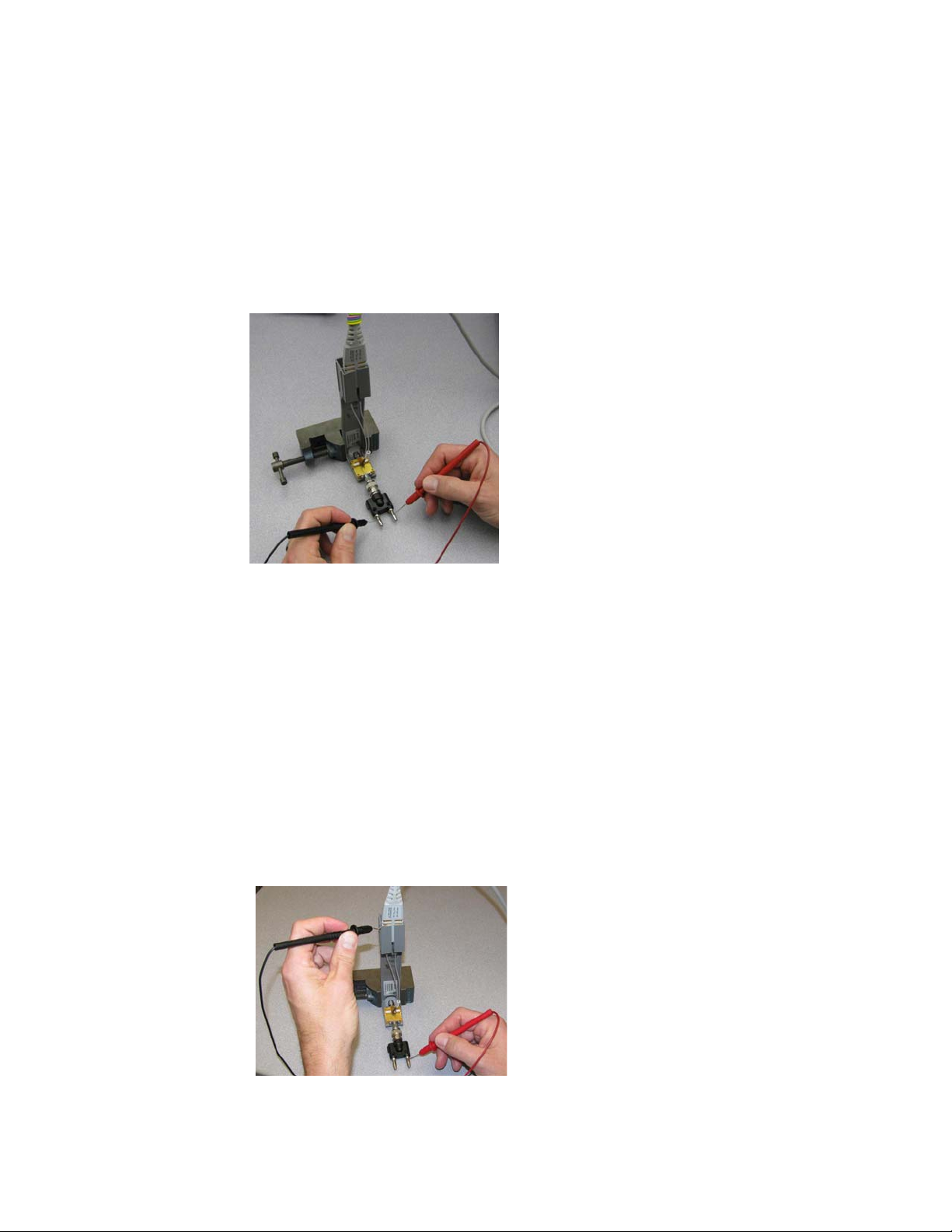
Performance Verification 6
Measuring Input Resistance for ZIF Probe Heads or Solder-in Probe Heads
1 Connect the BNC to SMA adapter and BNC to Banana Plug adapters as shown in
Figure 70.
2 Position the PV fixture on a table top and clamp it with a small bench vise to steady it.
Ensure that the PV fixture is flush with the table top so that when the banana plugs are
probed, it does not rock the PV fixture.
Figure 70 Measuring the differential input resistance of a ZIF or solder-in probe head
3 Connect the probe amplifier to the oscilloscope or power supply so it is powered.
4 Connect the ZIF or solder-in probe head to the probe amp and insert it into the PV fixture
as shown Figure 70.
5 Depress the pincher fingers on the PV fixture so they open and carefully insert the tip wires
under the pinchers. Release the pichers once the tips are inserted.
6 As shown in Figure 70, measure the DC input resistance between the banana plugs. Since
one tip wire is connected to the signal line and the other tip is connected to the PV fixture
ground, this is a measurement of the differential input resistance. It should be 100 kOhms
+/- 2% (98 to 102 kOhms).
7 To measure the single-ended input resistance, measure the resistance between the signal
plug of the banana adapter and the probe amplifier ground, which can be accessed as
shown in Figure 71 (through the vent window of the probe amplifier).
Figure 71 Measuring the single-ended input resistance of a ZIF or solder-in probe head
InfiniiMax III Series Probes User’s Guide 97
Page 98
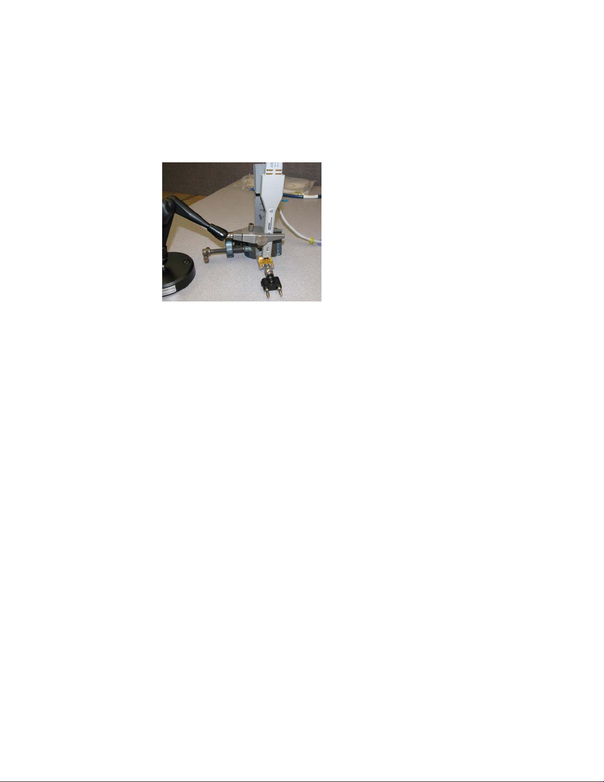
6 Performance Verification
Measuring Input Resistance for the Browser Probe Head
The following image shows the correct setup for measuring the differential input resistance
of the N5445A Browser probe head (Figure 72).
Figure 72 Setup for Measuring Input Resistance for Browser Probe Head
1 Set the browser for a fairly wide span (span does not impact this DC measurement).
2 Plug the probe amplifier into the browser.
3 Clamp the browser with the N2787A probe positioner.
4 Hold the browser with one hand and loosen the arm locking knob on the probe positioner
with the other hand.
5 Carefully position one tip over the signal trace on the PV fixture and the other over the
ground plane. Then let the weight of the browser slightly compress the tips so good
contact is made.
6 Now the differential and single-ended input resistance can be measured in the same
manner as for the ZIF and solder-in probe head procedure above.
98 InfiniiMax III Series Probes User’s Guide
Page 99
Performance Test Record
NOTE
The recommended test interval is 1 Year/2000 hours.
Keysight Technologies Keysight InfiniiMax III Series Probe
Model Number: Tested by:
Serial Number: Work Order Number:
Recommended next test date: Date:
Performance Verification 6
Probe Head
(only required to test one)
Bandwidth Performance Test
N5439A with N5440A ≥ 26 GHz
N5445A ≥ 28 GHz
DC Input Resistance Performance Test
N5439A with N5440A 98 to 102 kΩ (differential mode)
N5445A 98 to 102 kΩ (differential mode)
N5441A 98 to 102 kΩ (differential mode)
Test Limits Result Pass/Fail
49 to 51 kΩ (single-ended mode)
49 to 51 kΩ (single-ended mode)
49 to 51 kΩ (single-ended mode)
InfiniiMax III Series Probes User’s Guide 99
Page 100

6 Performance Verification
100 InfiniiMax III Series Probes User’s Guide
 Loading...