

Page 1
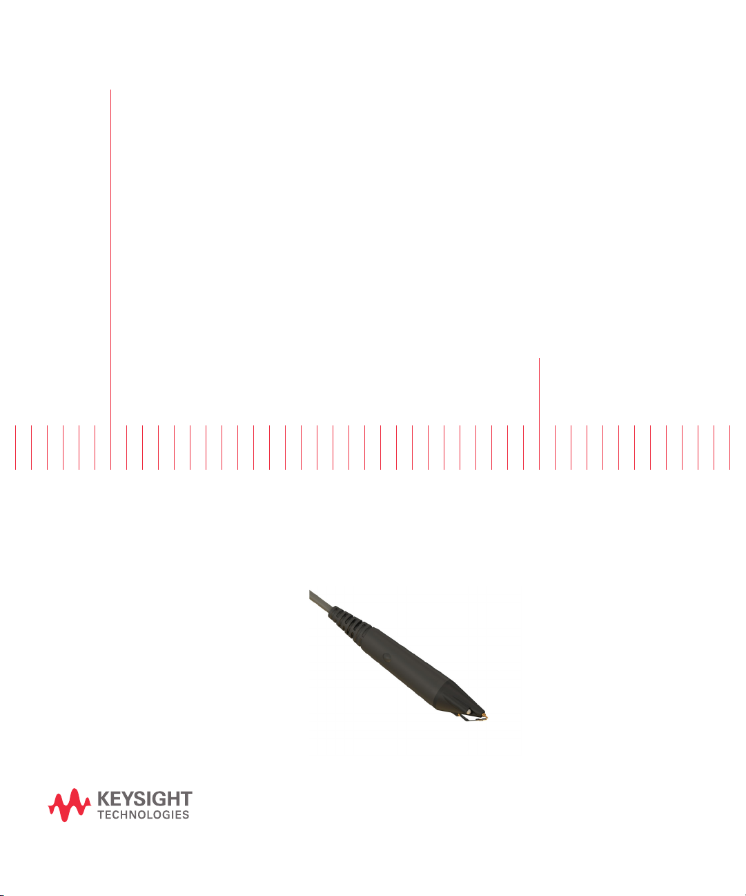
Keysight N2795/6A
Single-Ended Probes
User’s Guide
Page 2

Notices
© Keysight Technologies, Inc. 2010 - 2013,
2018
No part of this manual may be reproduced in
any form or by any means (including electronic storage and retrieval or translation into
a foreign language) without prior agreement
and written consent from Keysight Technologies, Inc. as governed by United States and
international copyright laws.
Manual Part Number
N2795–97004
Edition
October 2018
Published by:
Keysight Technologies, Inc.
1900 Garden of the Gods Road
Colorado Springs, CO 80907 USA
Warranty
The material contained in this document is
provided “as is,” and is subject to being
changed, without notice, in future editions.
Further, to the maximum extent permitted by
applicable law, Keysight disclaims all warranties, either express or implied, with regard
to this manual and any information contained
herein, including but not limited to the
implied warranties of merchantability and fitness for a particular purpose. Keysight shall
not be liable for errors or for incidental or
consequential damages in connection with
the furnishing, use, or performance of this
document or of any information contained
herein. Should Keysight and the user have a
separate written agreement with warranty
terms covering the material in this document
that conflict with these terms, the warranty
terms in the separate agreement shall control.
Technology Licenses
The hardware and/or software described in
this document are furnished under a license
and may be used or copied only in accordance with the terms of such license.
U.S. Government Rights
The Software is "commercial computer software," as defined by Federal Acquisition Regulation ("FAR") 2.101. Pursuant to FAR
12.212 and 27.405-3 and Department of
Defense FAR Supplement ("DFARS")
227.7202, the U.S. government acquires
commercial computer software under the
same terms by which the software is customarily provided to the public. Accordingly,
Keysight provides the Software to U.S. government customers under its standard commercial license, which is embodied in its End
User License Agreement (EULA), a copy of
which can be found at
http://www.keysight.com/find/sweula. The
license set forth in the EULA represents the
exclusive authority by which the U.S. government may use, modify, distribute, or disclose
the Software. The EULA and the license set
forth therein, does not require or permit,
among other things, that Keysight:
(1) Furnish technical information related to
commercial computer software or commercial computer software documentation that is
not customarily provided to the public; or (2)
Relinquish to, or otherwise provide, the government rights in excess of these rights customarily provided to the public to use,
modify, reproduce, release, perform, display,
or disclose commercial computer software or
commercial computer software documentation. No additional government requirements beyond those set forth in the EULA
shall apply, except to the extent that those
terms, rights, or licenses are explicitly
required from all providers of commercial
computer software pursuant to the FAR and
the DFARS and are set forth specifically in
writing elsewhere in the EULA. Keysight shall
be under no obligation to update, revise or
otherwise modify the Software. With respect
to any technical data as defined by FAR
2.101, pursuant to FAR 12.211 and 27.404.2
and DFARS 227.7102, the U.S. government
acquires no greater than Limited Rights as
defined in FAR 27.401 or DFAR 227.7103-5
(c), as applicable in any technical data.
52.227-14 (June 1987) or DFAR
252.227-7015 (b)(2) (November 1995), as
applicable in any technical data.
CAUTION. A CAUTION notice
denotes a hazard. It calls attention to an
operating procedure, practice, or the
like that, if not correctly performed or
adhered to, could result in damage to
the product or loss of important data.
Do not proceed beyond a CAUTION
notice until the indicated conditions are
fully understood and met.
WA R N I N G . A WARNING notice
denotes a hazard. It calls attention to
an operating procedure, practice, or the
like that, if not correctly performed or
adhered to, could result in personal
injury or death. Do not proceed beyond
a WARNING notice until the indicated
conditions are fully understood and
met.
2 N2795/6A User’s Guide
Page 3

Contents
Contents
1Using the Probes
Oscilloscope Compatibility / 7
Supplied Accessories / 8
Probe Headlight / 11
Using the Accessory Tips and Grounds / 12
Dynamic Range and Offset Voltage Limitations / 19
Functional Test / 20
Inspecting the Probe / 21
Returning the Probe for Service / 22
Safety Information / 23
2 Characteristics and Specifications
3Performance Data Plots
4 Performance Verification
N2795/6A User’s Guide
Dimensions / 27
Test 1. DC Input Resistance / 35
Test 2. Bandwidth / 36
Performance Test Record / 45
Page 4

Contents
4 N2795/6A User’s Guide
Page 5
Keysight N2795/6A Single-Ended Probes
User’s Guide
1 Using the Probes
Oscilloscope Compatibility 7
Supplied Accessories 8
Probe Headlight 11
Using the Accessory Tips and Grounds 12
Dynamic Range and Offset Voltage Limitations 19
Functional Test 20
Inspecting the Probe 21
Returning the Probe for Service 22
Safety Information 23
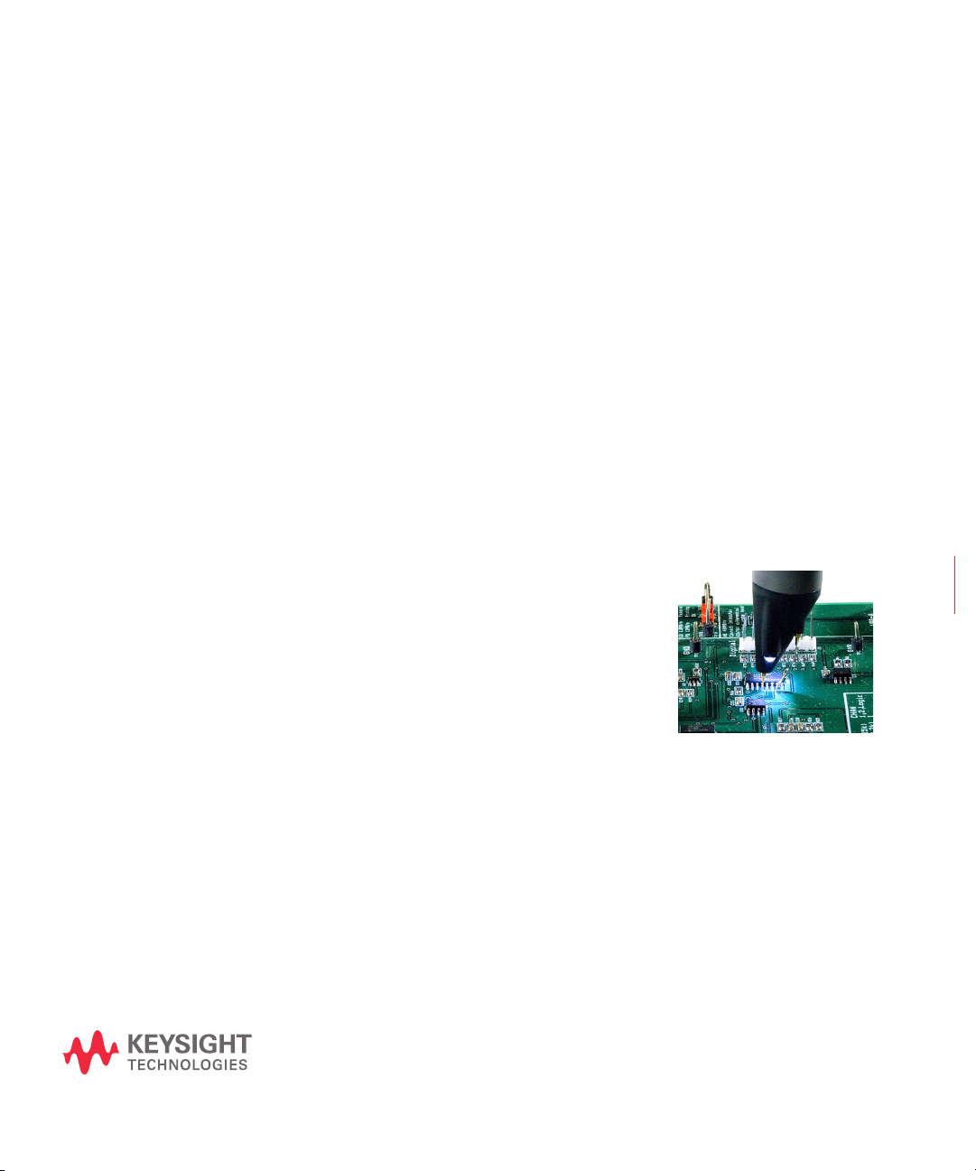
The N2795/6A are 1 and 2 GHz
single-ended active probes with the
AutoProbe interface (compatible with
Keysight’s InfiniVision and Infiniium
family of oscilloscopes). These probes
integrate many of the characteristics
needed for today’s general-purpose,
high-speed probing, component
design/characterization, and
educational research applications. Its 1MW input resistance and
extremely low input capacitance (1 pF) provide ultra low loading of
the DUT. This, accompanied with superior signal fidelity, makes
these probes useful for most of today’s digital logic voltages. And
with their wide dynamic range (±8V) and offset range (±12V for
N2796A, ±8V for N2795A), these probes can be used in a wide
variety of applications.
For high signal integrity probing, the N2795A 1 GHz and N2796A 2
GHz active probes are perfect complements to Keysight’s 500 MHz
– 600 MHz and 1 GHz bandwidth oscilloscopes, respectively. The
5
Page 6

1 Using the Probes
N2796A 2 GHz probe can also be used with Keysight’s 2.5 GHz or
higher bandwidth Infiniium scope as a low cost alternative to the
InfiniiMax probes.
The N2795/6A probes are powered directly by the InfiniiVision and
Infiniium AutoProbe interface, eliminating the need for an
additional power supply. The probes also come with a number of
accessories that allow for easy connections to the circuit under
test. Refer to “Supplied Accessories” on page 8.
WARNING Handle the probe with care to avoid injury, especially when it is fitted with
the sharp spring or rigid tip.
CAUTION This probe is an ESD sensitive devices, particularly at the probe tips. Follow
standard ESD precautions when handling. Remove tip accessories when
storing the probe.
CAUTION Before using the probe, refer to “Safety Information” on page 23.
CAUTION Handle the probe cable carefully to avoid damaging it through excessive
bending or pulling. Avoid any mechanical shocks to the probe in order to
guarantee accurate performance and protection.
Cleaning the Probe
Disconnect the probe from the oscilloscope and clean the probe
with a soft cloth dampened with a mild soap and water solution.
Make sure the probe is completely dry before reconnecting it to an
oscilloscope.
6 N2795/6A User’s Guide
Page 7
Oscilloscope Compatibility
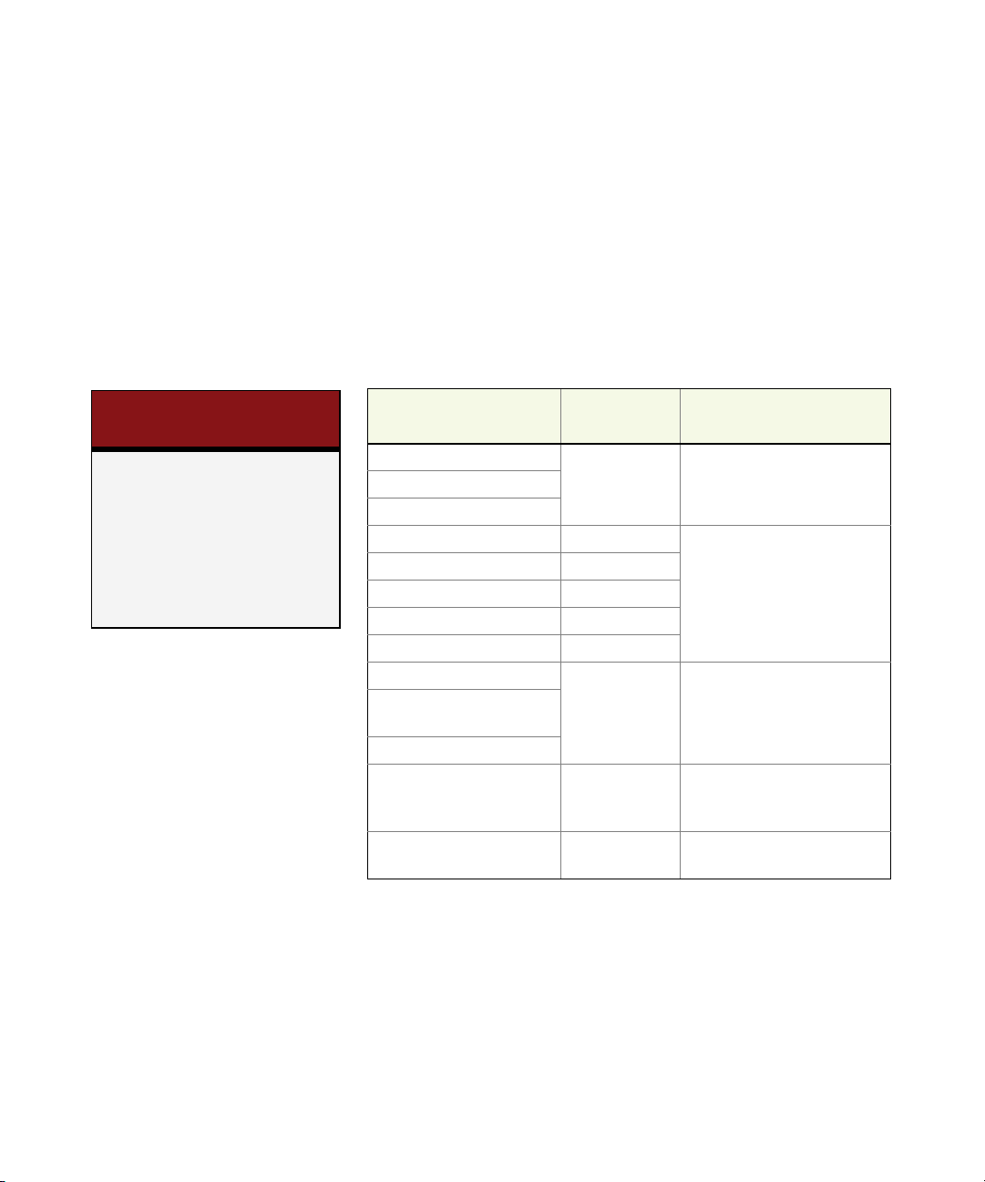
The N2795/6A probes are compatible with the Keysight
oscilloscopes shown in Tab l e 1 (those with the Keysight AutoProbe
Interface). The table also lists the minimum required firmware
version for the oscilloscope.
Table 1 Compatible Oscilloscopes and Probe Support
Using the Probes 1
Is Your Oscilloscope Software
Up-to-Date?
Keysight periodically releases
software updates to support your
probe, fix known defects, and
incorporate product enhancements.
To download the latest firmware, go to
www.keysight.com and search for
your oscilloscope’s topic. Click on the
“Drivers, Firmware & Software” tab.
Software
Oscilloscope
Infiniium Z-Series
Infiniium V-Series
Infiniium S-Series
Infiniium 90000 X-Series
Infiniium 90000 Q-Series
Infiniium 90000 Series >=2.50
Infiniium 9000 H-Series All
Infiniium 90000A-Series >=2.50
InfiniiVision 7000 Series >= 6.10 Two probes on 2 or 4-channel
InfiniiVision 6000 Series
(except 100 MHz model)
InfiniiVision 5000 Series
InfiniiVision 4000 X-Series All Four probes on 4-channel
InfiniiVision 3000 X-Series All Two probes on 2 or 4-channel
a Requires N5442A adapter.
a
a
Version
>=5.0 Four probes per scope
a
All Four probes on 4-channel
a
All
Maximum Number of Probes
Supported
scope.
scopes.
scope. Two probes on 2-channel
scope.
scopes.
N2795/6A User’s Guide 7
Page 8
1 Using the Probes
Supplied Accessories
Attaching Probe Accessories
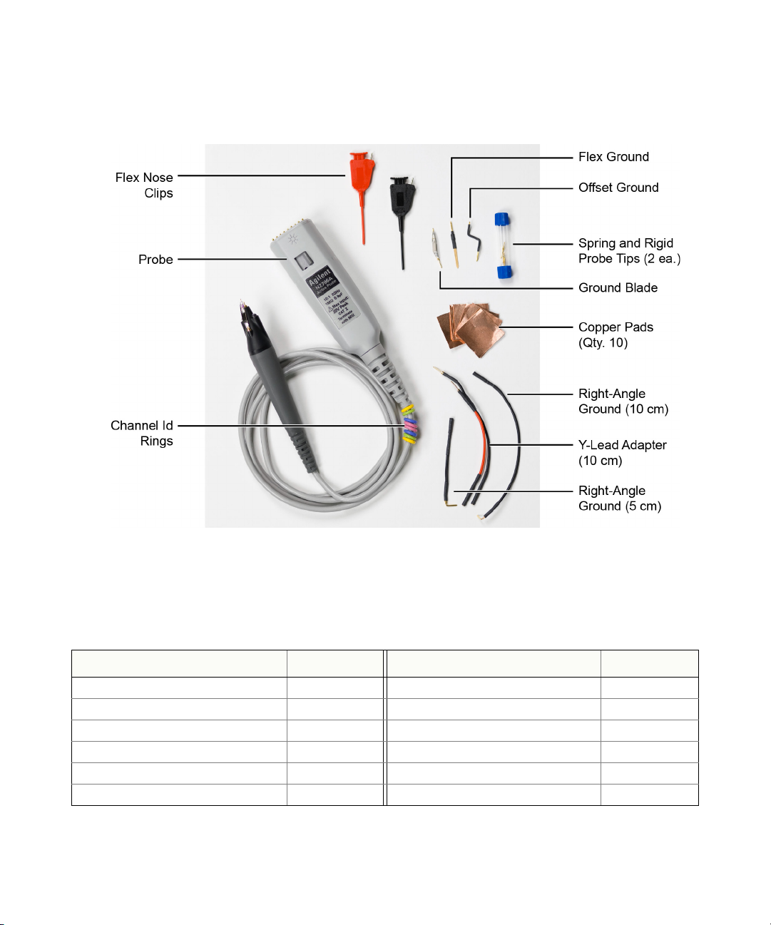
The probes come with the accessories shown in Figure 2 on page 9
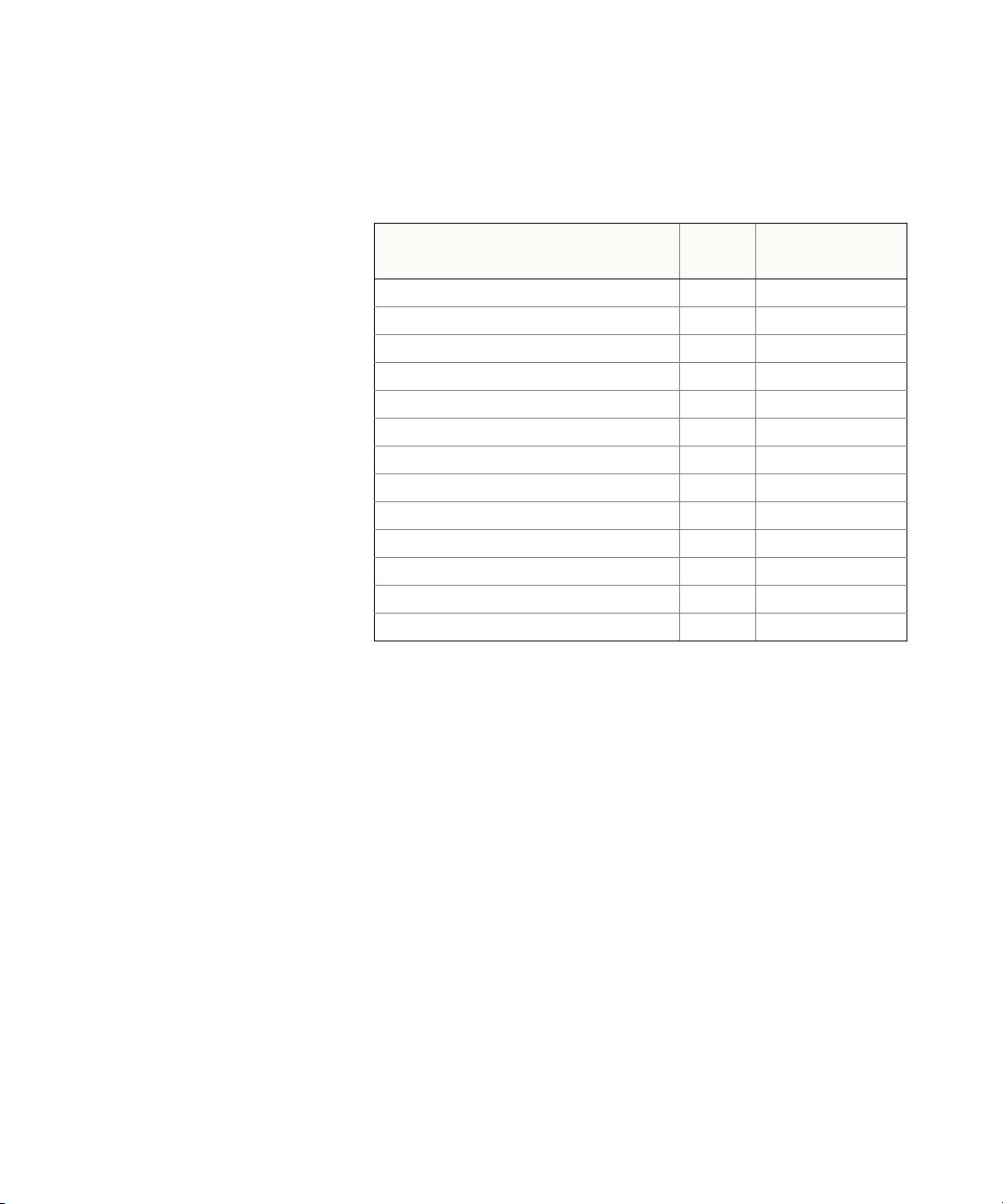
and listed in Tab le 2 on page 9. Ta ble 3 on page 10 shows the
replacement accessories available in the replacement accessory
kit.
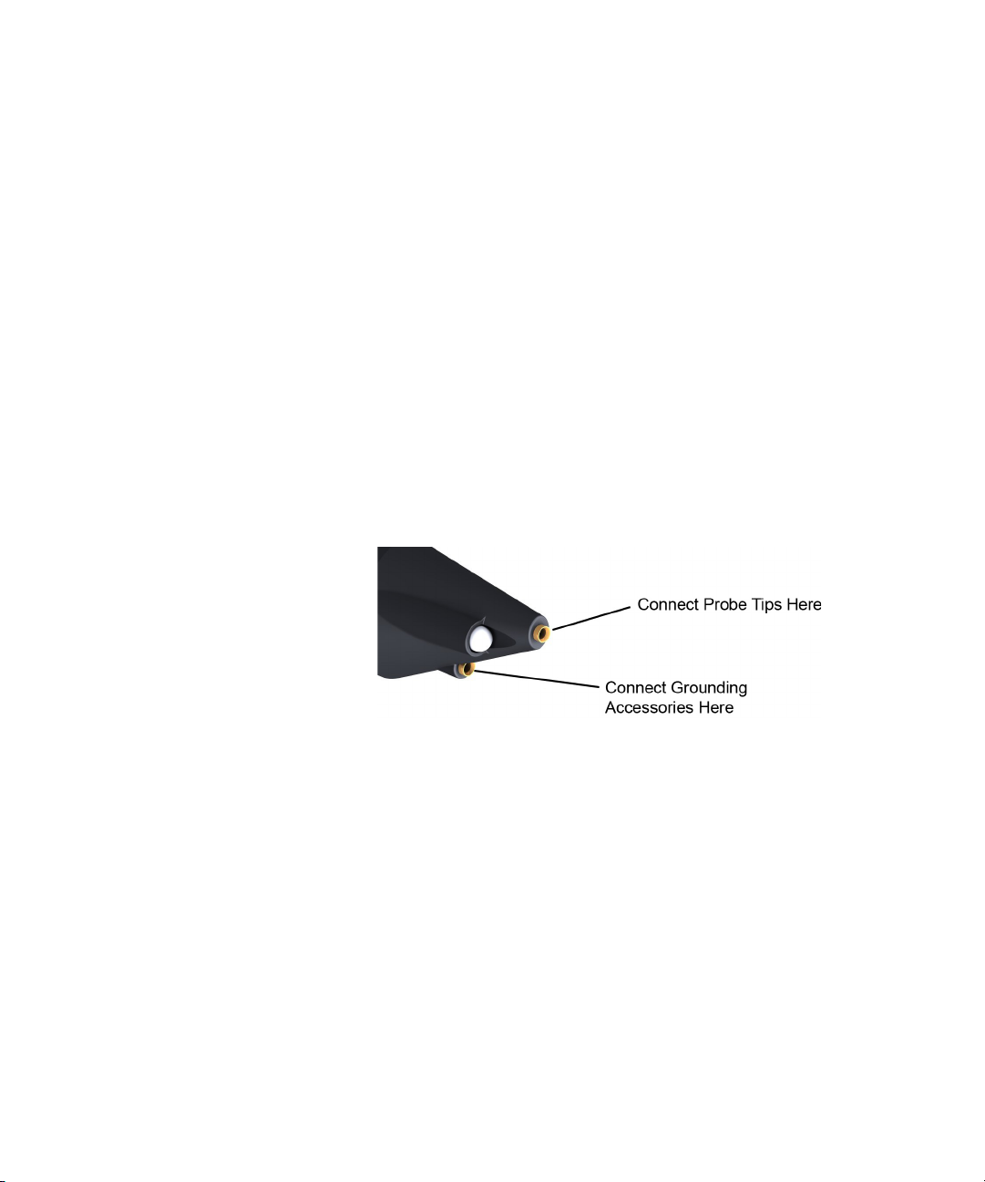
It’s easy to change the probe tip and ground accessories. Figure 1
shows locations for inserting the tip and the ground accessory. To
change an accessory, gently pull it straight out of its contact
socket along the axis of the probe. Once the accessory is removed,
insert the new accessory until it is seated in the contact socket. In
order to insert the probe tip completely into the housing, carefully
press the probe tip against a hard surface.
Figure 1 Tip and Grounding Connections
8 N2795/6A User’s Guide
Page 9
Using the Probes 1
Figure 2 Probe with Supplied Accessories
Table 2 Supplied Accessories
Accessory Quantity Accessory Quantity
Flex Nose Clip (red) 1 Right-Angle Ground (10 cm) 1
Flex Nose Clip (black) 1 Ground Blade 2
Rigid Probe Tip 2 Offset Ground 1
Spring Probe Tip 2 Flex Ground 1
Y-Lead Adapter (10 cm) 1 Copper Pads 10
Right-Angle Ground (5 cm) 1 Channel-Identification Rings 4 of each color
N2795/6A User’s Guide 9
Page 10
1 Using the Probes
Table 3 Replacement Accessory Kit
Part
Accessory Qty
Flex Nose Clip (red) 1 5061-7390
Flex Nose Clip (black) 1 5061-7391
Rigid Probe Tip 2 5061-7389
Spring Probe Tip 2 5061-7388
Y-Lead Adapter (10 cm) 1 5061-7392
Right-Angle Ground (5 cm) 2 5061-7399
Right-Angle Ground (10 cm) 2 5061-7400
Ground Blade 2 5061-7393
Offset Ground 2 5061-7394
Flex Ground 2 5061-7397
Ground Lead (6 cm) 2 5061-7395
Ground Lead (12 cm) 2 5061-7396
Copper Pads 10 0960-2908
Number
Channel-Identification Rings
When multiple probes are connected to the oscilloscope, the
channel identification rings allow you to quickly determine which
channel input is associated with each probe. On the probe, place
one colored ring near the probe’s channel connector and place an
identical color ring near the probe head.
10 N2795/6A User’s Guide
Page 11
Probe Headlight
Using the Probes 1
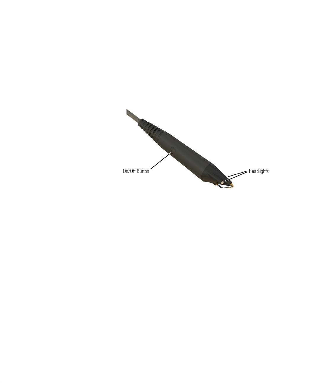
The probe is equipped with a white LED headlight to illuminate the
area around the probe tip. This headlight has a fixed intensity and is
turned on and off by pressing the button that is located on the
probe’s body.
Figure 3 Headlight and Button
N2795/6A User’s Guide 11
Page 12
1 Using the Probes
Using the Accessory Tips and Grounds
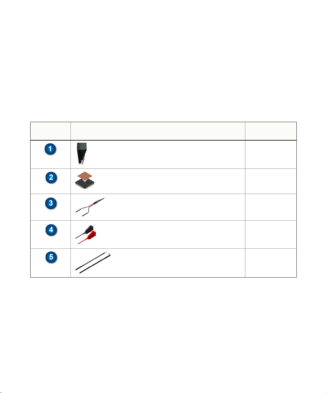
This section presents the various probe accessory configurations
listed in order of available bandwidth for your measurements.
Select the configuration to match your measurement needs,
including ease of use.
Table 4 Probe Configurations in Order of Decreasing Bandwidth
Recommended
Order of Use
Probe Configuration Topic
“Rigid or Spring Tips with Offset Ground or Ground Blade” on
page 13
“Copper Pads with Flex Ground” on page 15 900 MHz (N2795A)
“Y-Leads Adapter with 0.1” Headers” on page 16 750 MHz (N2795A)
“Flexible Nose Clips” on page 17 500 MHz (N2795A)
“Ground Leads and Right-Angle Ground Leads” on
page 18
Typical
Bandwidth
1 GHz (N2795A)
2 GHz (N2796A)
1.8 GHz (N2796A)
1 GHz (N2796A)
500 MHz (N2796A)
Unspecified
12 N2795/6A User’s Guide
Page 13
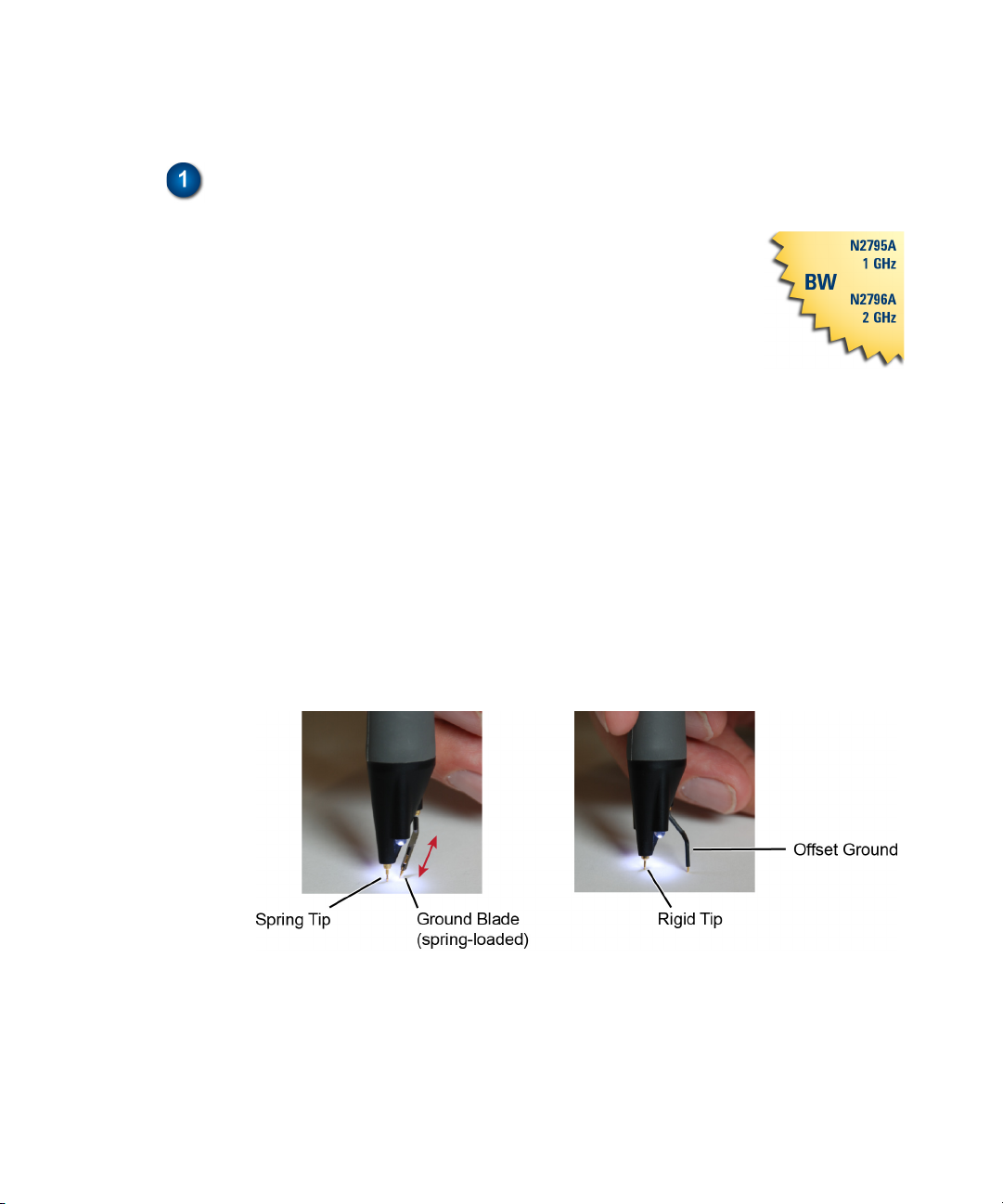
Rigid or Spring Tips with Offset Ground or Ground Blade
These rigid and spring-loaded tips are
replaceable. To change the probe tip, pull it
straight out of its contact socket along the axis
of the probe. Once the probe tip is removed,
the new tip can be inserted into the contact
socket along the axis of the probe. In order to
insert the probe tip completely into the
housing, carefully press the probe tip against a hard surface.
It is recommended that the spring tips be used with the ground
blade as both the tips and ground blade are spring-loaded and will
maintain contact with the device under test even when your hand
moves slightly.
The rigid/spring tips and grounds can be mixed with no effect on
performance. It is simply a matter of personal preference. Spring
loaded probe tips offer a method of probing signals that is less
susceptible to vibration or movement than traditional rigid tips.
Many users find it easier to use this type of tip. The spring loaded
tips work when they are either partially or fully compressed and are
protected against over compression damage. The recommended
grounding accessory for the rigid probe tip is the offset ground.
Using the Probes 1
Figure 4 Sprint and Rigid Tips with Offset and Blade Ground
N2795/6A User’s Guide 13
Page 14
1 Using the Probes
WARNING Handle the probe with care to avoid injury, especially when it is fitted with
the sharp rigid or spring tip.
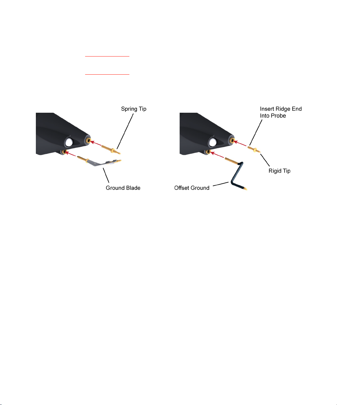
When inserting the tip, insert the end with the ridge into the probe
head as shown in Figure 5.
Figure 5 Inserting the Tips and Grounds
14 N2795/6A User’s Guide
Page 15
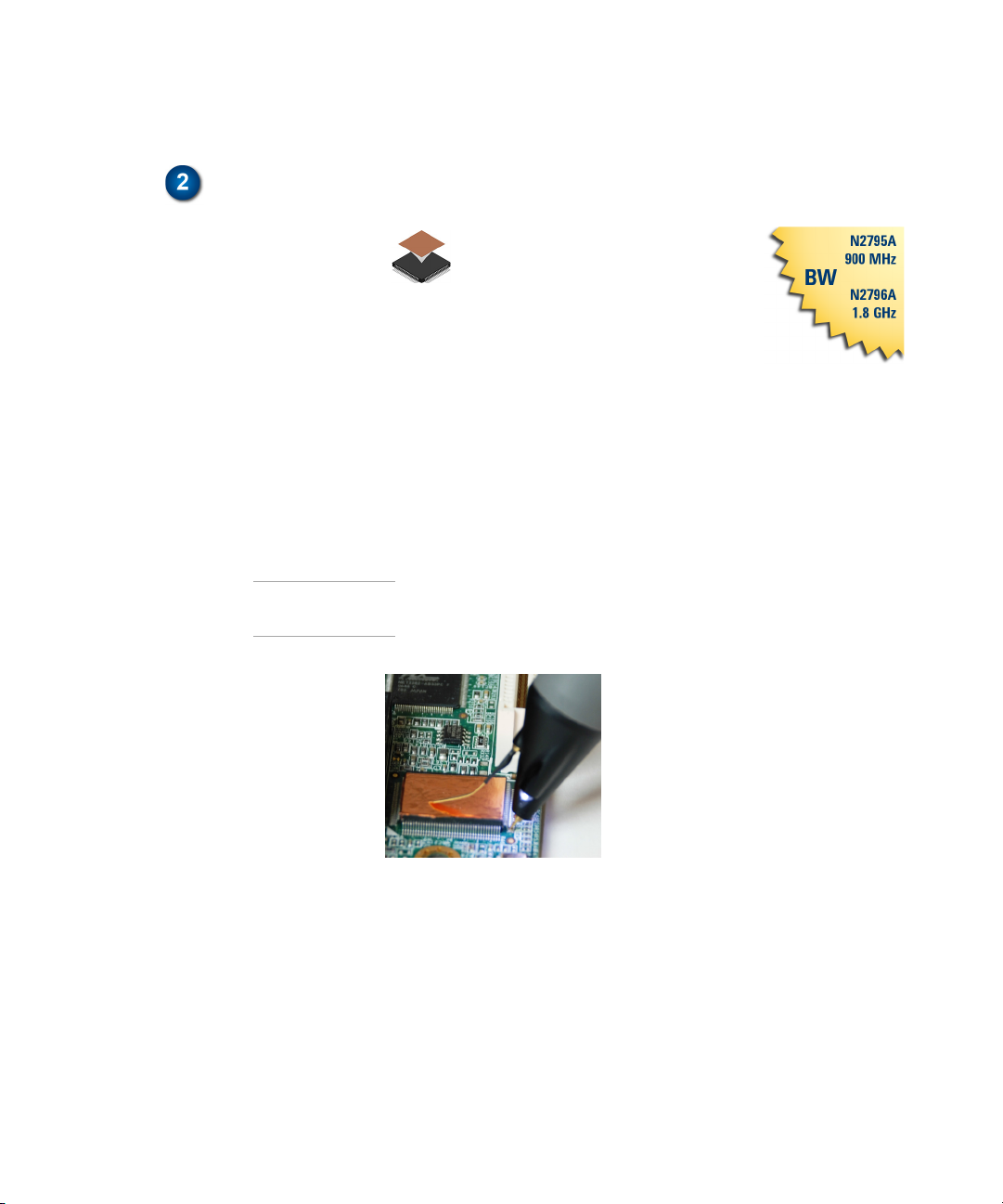
Copper Pads with Flex Ground
These self adhesive copper pads
can be attached on top of an IC
and connected to its ground pins
to create a convenient ground
plane for the probe to connect to.
When used with the flex ground, this method
provides an ideal ground connection for
probing signals with high frequency content. However, to maximize
the performance of this setup, you need to solder as many jumper
wires as is practical from the ground pins of the package to the
copper pad. The more ground connections, the less inductance in
the ground path and the higher the bandwidth capability of the
measurement. Insert the Flex Ground and bend it into a shape that
makes it easy to contact the copper ground pad on top of the
package.
NOTE The bandwidth is highly dependent on the number of ground connections
between the copper pad and the device under test.
Using the Probes 1
Figure 6 Copper Pad on IC
N2795/6A User’s Guide 15
Page 16
1 Using the Probes
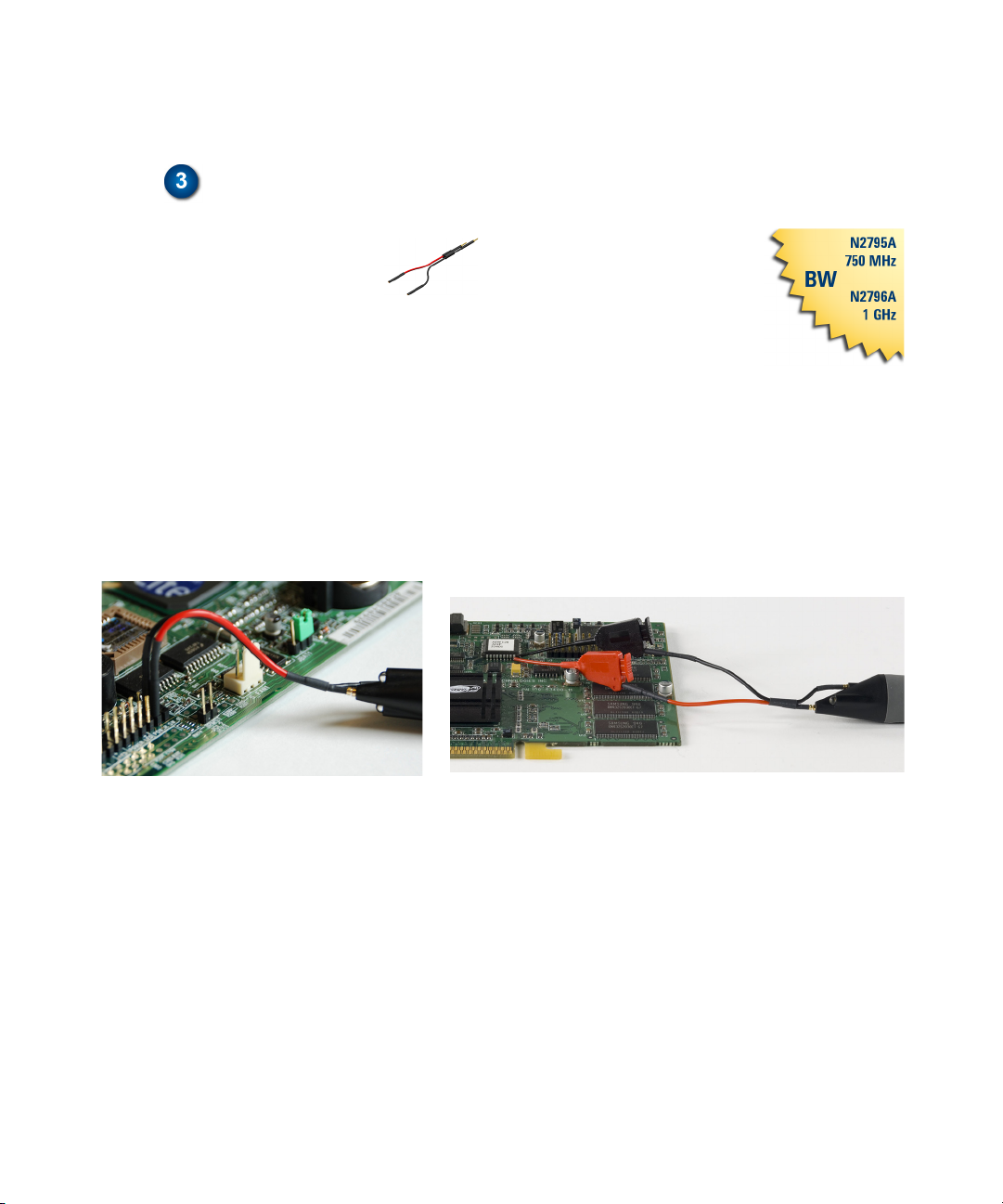
Y-Leads Adapter with 0.1” Headers
The Y-lead adapter offers a
convenient and reliable method
to connect both the probe
signal and ground to probe
points on the board or other probe
accessories. For example, this can used to
connect to connector headers or other
accessories like the Flex Nose Clip Adapter as seen in the following
pictures.
The sockets accept 0.56-0.86 mm round and 0.64 mm square
(0.022 - 0.034 inch round and 0.025 inch square) diameter pins.
The maximum insertion depth is 7.5 mm (0.295 inch) and the outer
insulation of the socket is less than 2.54 mm. You can use it for
2.54 mm pitch (0.1 inch) terminals.
Figure 7 Probe with Y-Leads Attached
16 N2795/6A User’s Guide
Page 17
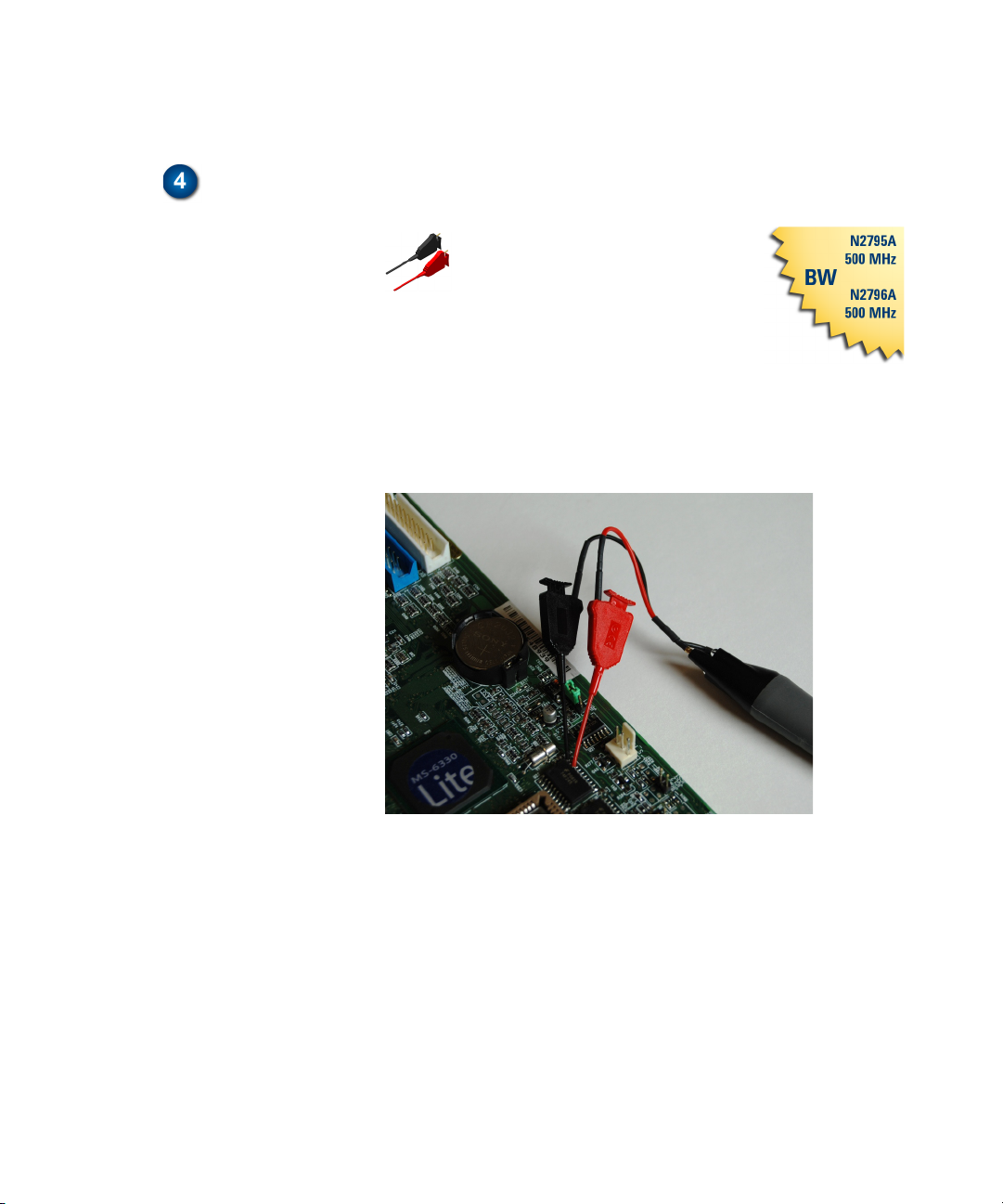
Flexible Nose Clips
smaller. With today’s miniature IC- and
component-packaging techniques, these clips
can make probing challenging devices much
easier. Most users prefer to attach the clips to the probe via the
Y-lead adapter as shown in the picture below. Press the back of the
flex nose clip to extend the grasping hook and then release to
tighten the hook around the component you are testing.
Using the Probes 1
You can use flexible nose clips to
make connections to components
or wires with leads that are 1.01
mm (0.04 inches) in diameter or
Figure 8 Probe with Flexible Nose Clips Attached
N2795/6A User’s Guide 17
Page 18
1 Using the Probes
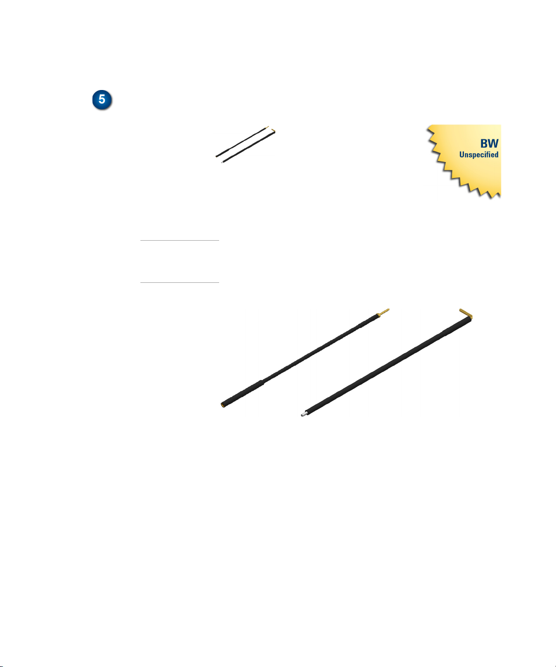
Ground Leads and Right-Angle Ground Leads
These ground leads can be
used to reach grounding
locations that are farther
away from the probing
location than can be reached by either the
ground blade or offset ground. However, the
longer leads means they have a larger
inductance in the ground return path which corresponds to a lower
performance than the ground blade and offset ground.
NOTE The straight leads are not included with the probe. They must be ordered as
a replacement kit. For more information about the replacement kits, refer to
Table 3 on page 10.
Figure 9 Straight and Right-Angle Ground Leads
18 N2795/6A User’s Guide
Page 19
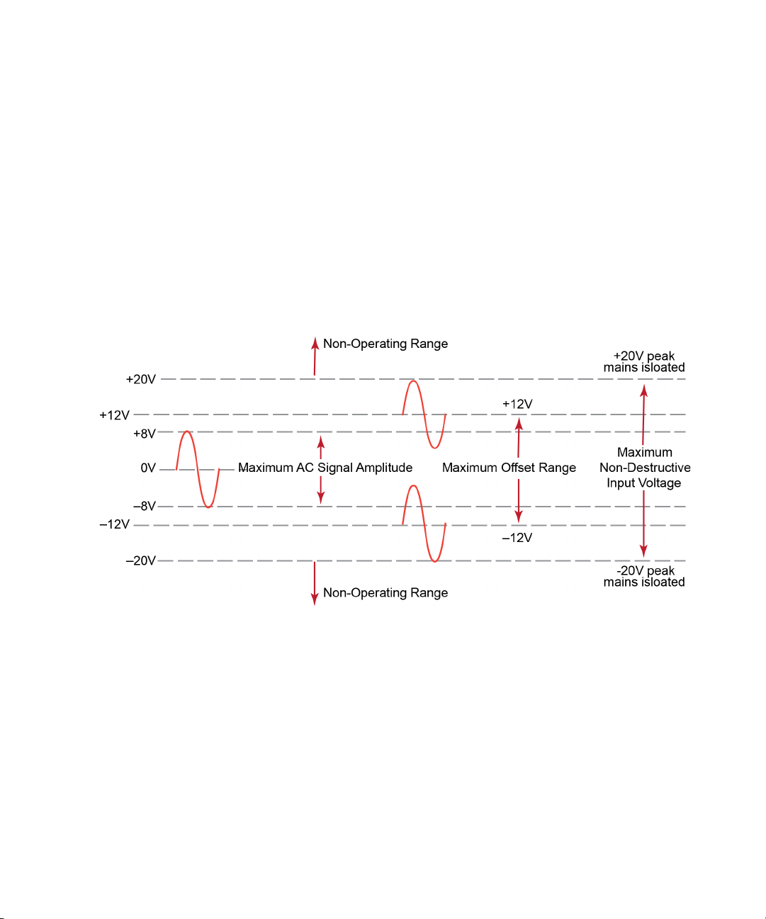
Dynamic Range and Offset Voltage Limitations
With 16Vpp (±8V) of dynamic range and ±8V (N2795A) or ±12V
(N2796A) of offset range, the probes have a wide measuring range
of ±20V, which allows them to be used for a wide variety of
applications. For example, if you wanted to measure small AC noise
riding on top of a +10V DC signal, you could use DC offset to
position the signal at the center of the screen to keep the probe
within its dynamic range. You could then zoom in to see the detail
at a higher resolution. Trying to measure a signal out of the
dynamic range may result in a clipped or distorted waveform.
Using the Probes 1
Figure 10 Dynamic Range and Offset Limits
N2795/6A User’s Guide 19
Page 20

1 Using the Probes
Functional Test
Use the following generic measurement procedure to ensure that
your probe is functioning properly.
1 Connect the probe to an oscilloscope channel input and ensure
the input impedance of the oscilloscope matches the output
impedance of the probe (50W).
2 Connect a grounding accessory to the probe and connect the
ground to the ground terminal on the oscilloscope.
3 Connect the probe tip to the oscilloscope’s probe compensation
output.
4 Enable autoscale on the oscilloscope.
5 A square wave should now be displayed on the oscilloscope, if
the probe is functioning properly.
20 N2795/6A User’s Guide
Page 21

Inspecting the Probe
Using the Probes 1
• Inspect the shipping container for damage.
Keep the damaged shipping container or cushioning material
until the contents of the shipment have been checked for
completeness and the probe has been checked mechanically
and electrically.
• Check the accessories.
• If the contents are incomplete or damaged, notify your Keysight
Technologies Sales Office.
• Inspect the probe.
If there is mechanical damage or defect, or if the probe does not
operate properly or pass calibration tests, notify your Keysight
Technologies Sales Office.
If the shipping container is damaged, or the cushioning
materials show signs of stress, notify the carrier as well as your
Keysight Technologies Sales Office. Keep the shipping materials
for the carrier’s inspection. The Keysight Technologies office will
arrange for repair or replacement at Keysight Technologies’
option without waiting for claim settlement.
N2795/6A User’s Guide 21
Page 22

1 Using the Probes
Returning the Probe for Service
If the probe is found to be defective we recommend sending it to an
authorized service center for all repair and calibration needs.
Perform the following steps before shipping the probe back to
Keysight Technologies for service.
1 Contact your nearest Keysight sales office for information on
obtaining an RMA number and return address.
2 Write the following information on a tag and attach it to the
malfunctioning equipment.
• Name and address of owner
• Product model number (for example, N2795A)
• Product Serial Number (for example, MYXXXXXXXX)
• Description of failure or service required
NOTE Include probing and browsing tips if you feel the probe is not meeting
performance specifications or a yearly calibration is requested.
3 Protect the probe by wrapping in plastic or heavy paper.
4 Pack the probe in the original carrying case or if not available
use bubble wrap or packing peanuts.
5 Place securely in sealed shipping container and mark container
as "FRAGILE".
NOTE If any correspondence is required, refer to the product by serial number and
model number.
Contacting Keysight Technologies
For technical assistance, contact your local Keysight Call Center.
• In the Americas, call 1 (800) 829-4444
• In other regions, visit http://www.keysight.com/find/assist
Before returning an instrument for service, you must first call the
Call Center at 1 (800) 829-4444.
22 N2795/6A User’s Guide
Page 23

Safety Information
WARNING To avoid personal injury and to prevent fire or damage to this product or
WARNING Handle the probe with care to avoid injury, especially when it is fitted with
WARNING Handle Probe Tips and Accessories Carefully.
Using the Probes 1
This apparatus has been designed and tested in accordance with
IEC 61010-031, Safety requirements for hand-held probe
assemblies for electrical measurement and test. Before applying
power, verify that the correct safety precautions are taken as
described in the following warnings.
products connected to it, review and comply with the following safety
precautions. Be aware that if you use this probe assembly in a manner not
specified, the protection this product provides may be impaired.
the sharp spring or rigid tip.
Some of the probe tips and accessories are very sharp (the browser tips, for
example). You should handle these with care to avoid personal injury.
WARNING Use Only Grounded Instruments.
Do not connect the probe’s ground lead to a potential other than earth
ground. Always make sure the probe and the oscilloscope are grounded
properly.
WARNING Connect and Disconnect Properly.
Connect the probe to the oscilloscope and connect the ground lead to earth
ground before connecting the probe to the circuit under test. Disconnect
the probe input and the probe ground lead from the circuit under test
before disconnecting the probe from the oscilloscope.
WARNING Observe Probe Ratings.
Do not apply any electrical potential to the probe input which exceeds the
maximum rating of the probe. Make sure to comply with the voltage versus
frequency derating curve found in this manual.
N2795/6A User’s Guide 23
Page 24

1 Using the Probes
WARNING These probes are for use only on circuits that are NOT directly connected to
mains. These are NOT intended for measurements on CAT II, CAT III, or CAT
IV circuits.
WARNING Keep Away From Live Circuits.
Avoid open circuitry. Do not touch connections or components when power
is present.
WARNING Indoor Use Only.
Do not operate in wet/damp environments. Keep product surfaces dry and
clean.
WARNING Periodically inspect the probe and probe wires. Do not use a probe which is
cracked, damaged, or has defective leads. If a failure is suspected, do not
use the probe. Contact Keysight Technologies for technical assistance.
CAUTION The probe cable is a sensitive part of the probe and, therefore, you should be
careful not to damage it through excessive bending or pulling. Avoid any
mechanical shocks to this product in order to guarantee accurate
performance and protection.
WARNING Whenever it is likely that the ground protection is impaired, you must make
the instrument inoperative and secure it against any unintended operation.
WARNING To avoid dangerous electric shock, do not attempt to perform any service
to the probe. Service should be carried out by a Keysight Technologies
authorized service personnel. For any service needs, contact Keysight
Technologies. Refer to the topic “Returning the Probe for Service” on
page 22 to know more.
WARNING Do not install substitute parts or perform any unauthorized modification to
the instrument.
WARNING Capacitors inside the instrument may retain a charge even if the instrument
is disconnected from its source of supply.
24 N2795/6A User’s Guide
Page 25
Using the Probes 1
WARNING Do not operate the instrument in the presence of flammable gasses or
fumes. Operation of any electrical instrument in such an environment
constitutes a definite safety hazard.
WARNING Do not use the instrument in a manner not specified by the manufacturer.
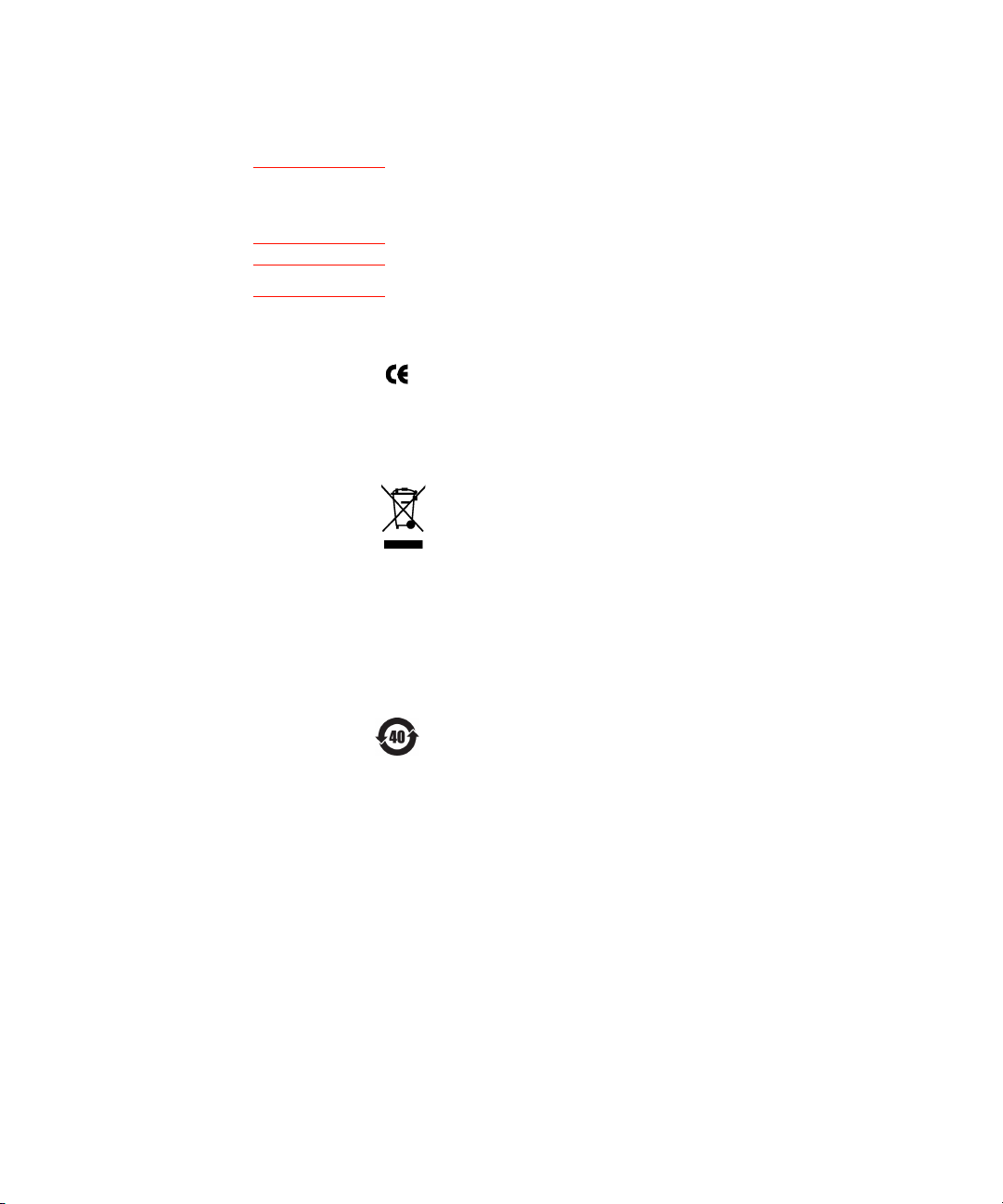
Instrument Markings The CE mark is a registered trademark of the European
Community. ISM GRP 1-A denotes the instrument is an
Industrial Scientific and Medical Group 1 Class A product.
ICES/NMB-001 indicates product compliance with the
Canadian Interference-Causing Equipment Standard.
This product complies with the WEEE Directive
(2002/96/EC) marking requirements. The affixed label
indicates that you must not discard this
electrical/electronic product in domestic household
waste. Product Category: With reference to the equipment
types in the WEEE Directive Annex I, this product is
classed as a “Monitoring and Control instrumentation”
product. Do not dispose in domestic household. To return
unwanted products, contact your local Keysight office, or
refer to www.keysight.com for more information.
This symbol indicates the Environmental Protection Use
Period (EPUP) for the product’s toxic substances for the
China RoHS requirements.
N2795/6A User’s Guide 25
Page 26
1 Using the Probes
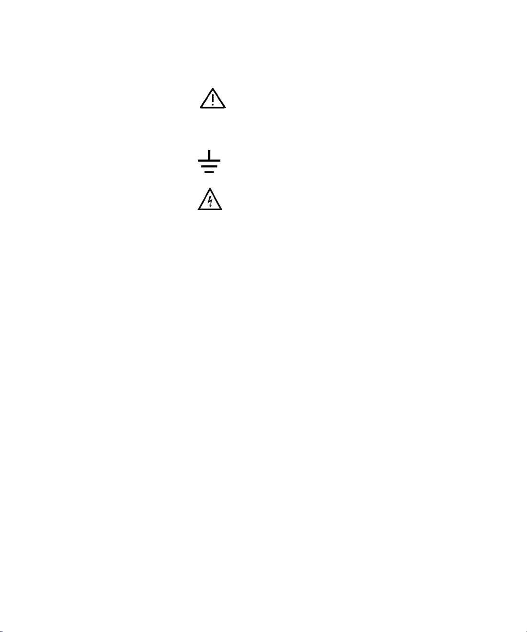
Safety Notices Instruction manual symbol: The product is marked with
this symbol when it is necessary for you to refer to the
instruction manual in order to protect against damage to
the product or personal injury.
Earth terminal symbol: Used to indicate a circuit common
connected to grounded chassis.
Hazardous voltage symbol.
26 N2795/6A User’s Guide
Page 27
Keysight N2795/6A Single-Ended Probes
User’s Guide
2 Characteristics and
Specifications
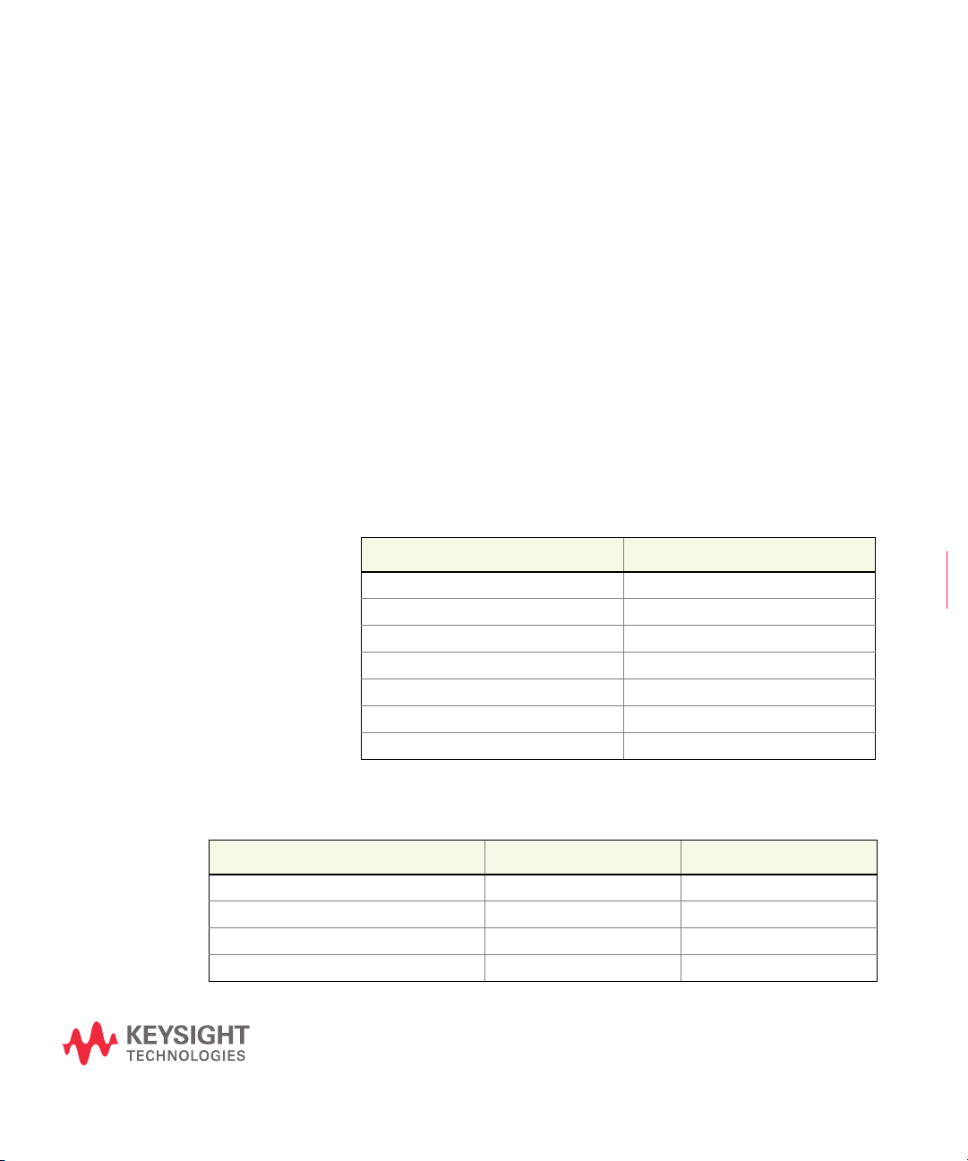
This chapter provides the characteristics and specifications for the
N2795/6A probes. The probe and oscilloscope should be warmed
up for at least 20 minutes before any testing and the environmental
conditions should not exceed the probe’s specified limits.
Table 5 Environmental Specifications
Parameter Characteristic
Operating Temperature 0°C to +50°C
Non-Operating Temperature –40°C to +70°C (–40°F to +158°F)
Altitude Operating; 4,000m (13,000 ft)
Operating Humidity 95% room humidity at +40°C
Non-Operating Humidity 90% room humidity at +65°C
ESD 8 kV HBM
Use indoor
Table 6 Electrical Characteristics and Specifications (Sheet 1 of 2)
Item N2795A N2796A
Attenuation Ratio (at DC) 10:1 ± 0.5% 10:1 ± 0.5%
Bandwidth (–3 dB)
Probe Risetime (calculated, 10% – 90%) 350 ps 175 ps
Input Dynamic Range –8V to +8V (DC or Peak AC) –8V to +8V (DC or Peak AC)
a
1 GHz 2 GHz
27
Page 28
2 Characteristics and Specifications
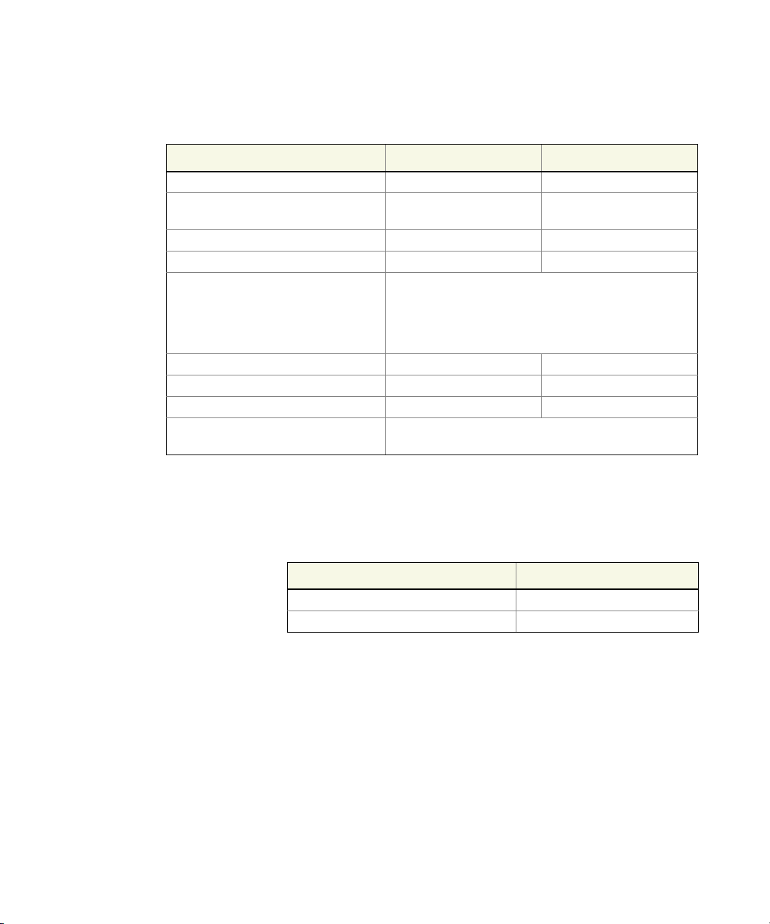
Table 6 Electrical Characteristics and Specifications (Sheet 2 of 2)
Item N2795A N2796A
Input Resistance
Non-Destructive Maximum Input Voltage –20V to +20V peak input,
Offset Range ±8V ±12V
DC Offset Error (Output Zero) < ±1 mV < ±1 mV
Flatness (both models) Typical 0.4 dB (100 kHz – 100 MHz)
Input Capacitance 1 pF 1 pF
Probe Noise (Referred to Input) < 2.5 mV
Output Impedance 50Ω 50Ω
Internal Power Keysight AutoProbe Interface from scope (InfiniiVision and
a Denotes warranted electrical specification after 20 minute warm-up. All others are typical.
b N2796A only
a
1 MΩ +0%, –2.5% 1 MΩ +0%, –2.5%
mains isolated
rms
–20V to +20V peak input,
mains isolated
Typical 0.6 dB (100 MHz – 500 MHz)
Typical 0.8 dB (500 MHz – 1 GHz)
Typical 1.3 dB (1 GHz – 2 GHz)
< 2.5 mV
b
rms
Infiniium models)
Table 7 Mechanical Characteristics
Parameter Characteristic
Approximate Weight (probe only) 100g
Cable Length 1.3m
28 N2795/6A User’s Guide
Page 29
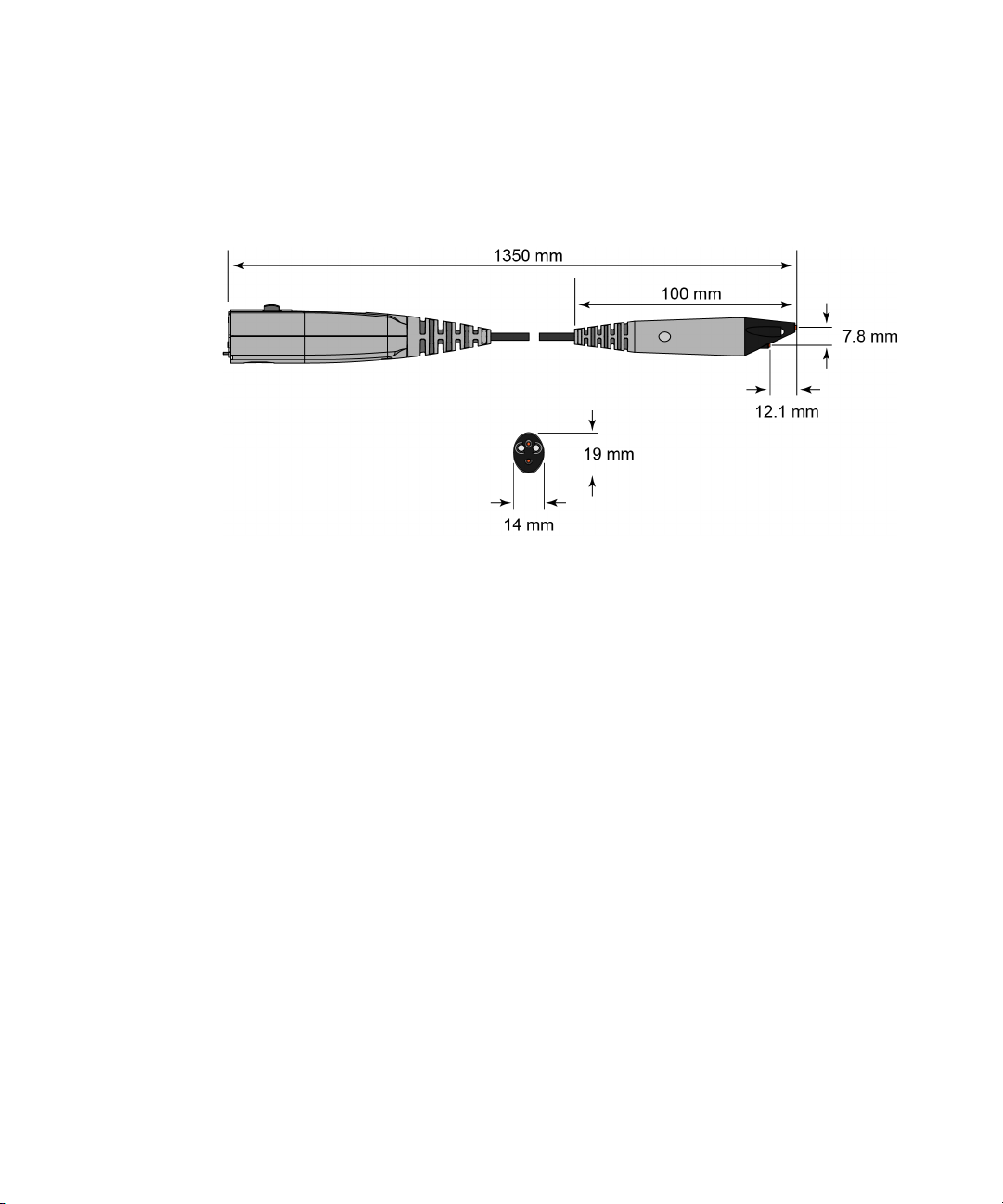
Dimensions
Characteristics and Specifications 2
N2795/6A User’s Guide 29
Page 30

2 Characteristics and Specifications
30 N2795/6A User’s Guide
Page 31
Keysight N2795/6A Single-Ended Probes
User’s Guide
3 Performance Data
Plots
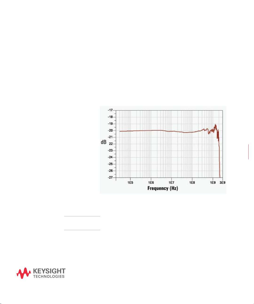
Figure 11 Frequency Response of N2796A (Vout/Vin)
NOTE Figure 11 is for the spring/rigid probe tip and an offset ground or ground
blade.
31
Page 32
3 Performance Data Plots
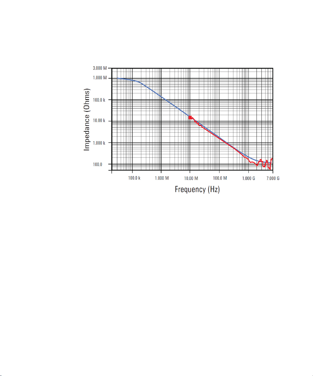
Figure 12 Input Impedance Over Frequency
(Red = measured, Blue = model)
32 N2795/6A User’s Guide
Page 33
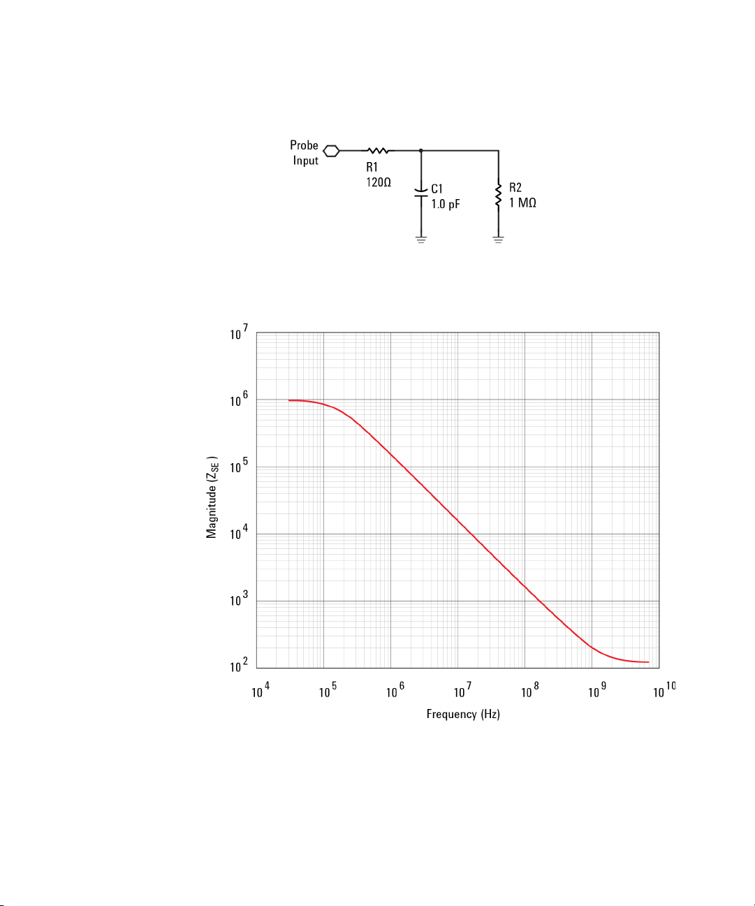
Figure 13 Input Impedance Equivalent Model
Performance Data Plots 3
Figure 14 Typical Input Impedance Plot
N2795/6A User’s Guide 33
Page 34

3 Performance Data Plots
34 N2795/6A User’s Guide
Page 35

Keysight N2795/6A Single-Ended Probes
User’s Guide
4 Performance
Verification
Test 1. DC Input Resistance 37
Test 2. Bandwidth 38
Performance Test Record 47
These procedures are used to test the warranted specifications for
the N2795/6A single-ended active probes. The recommended
calibration test interval is once a year or as required. Use the
equipment listed in.
CAUTION Electrostatic discharge (ESD) can quickly and imperceptibly damage or
destroy high performance probes, resulting in costly repairs. Always wear a
wrist strap when handling probe components and insure that cables are
discharged before being connected.
35
Page 36
4 Performance Verification
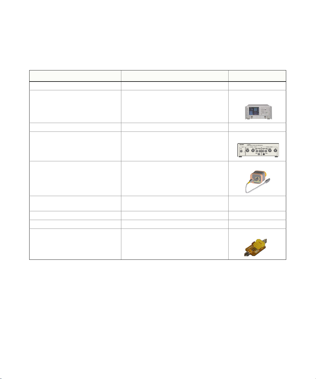
Table 8 Required Test Equipment
Test Equipment Critical Specification Model Number
Digital Multimeter (DMM) Resistance ±1% Keysight 34401A
Vector Network Analyzer (VNA) 13 GHz sweep range full 2 port cal Option 1D5 Keysight 8720ES
Calibration Standards No Substitute Keysight 85052D
External Power Supply No Substitute Keysight 1143A
AutoProbe Interface Adapter No Substitute Keysight N1022A/B
Outside thread 3.5 mm (male) to 3.5 mm
(female) adapter
Cable (2) 3.5 mil; SMA; High Quality Keysight 8120-4948
Cable 1.5 mil Probe Power Extension No Substitute Keysight 01143-61602
PV/DS Test Board No Substitute (In E2655B Kit) Keysight E2655-66503
No Substitute Keysight 5062-1247
36 N2795/6A User’s Guide
Page 37

Test 1. DC Input Resistance
Procedure
1 Connect the DMM probes between the probe tip and ground at
the tip of the probe.
2 Set up the DMM to measure resistance. The resistance should
read 1 MW + 0%, –2.5%.
3 Record the resistance in Tab le 9 on page 47.
Performance Verification 4
N2795/6A User’s Guide 37
Page 38

4 Performance Verification
Test 2. Bandwidth
Using the 8720ES VNA successfully
This test ensures that the Probe meets its specified bandwidth.
N2795A bandwidth:. . . . . . . . . . . . . . . . . . . . . . . . . . . . . . . . . . . . . . . . 1 GHz
N2796A bandwidth:. . . . . . . . . . . . . . . . . . . . . . . . . . . . . . . . . . . . . . . . 2 GHz
NOTE Allow the probe to warm up for at least 20 minutes.
Remember these simple guidelines when working with the 8720ES
VNA during this procedure.
• Sometimes it may take a few seconds for the waveforms to
settle completely. Allow time for waveforms to settle before
continuing.
• Make sure all connections are tight and secure. If needed, use a
vise to hold the cables and test board stable while making
measurements.
• Be careful not to cross thread or force any connectors. This
could be a very costly error to correct.
Procedure
Initial Setup
1 Turn on the 8720ES VNA and let warm up for 20 minutes.
2 Press the green [Preset] key on the 8720ES VNA.
3 On the VNA, press the [Power] key and set the power to 0 dBm.
4 On the VNA, press the [AVG] key and then select the Averaging
Factor screen key. Set averaging to 4.
5 On the VNA, press the [Sweep Setup] key and then press the
sweep type menu screen key. Select the log freq screen key.
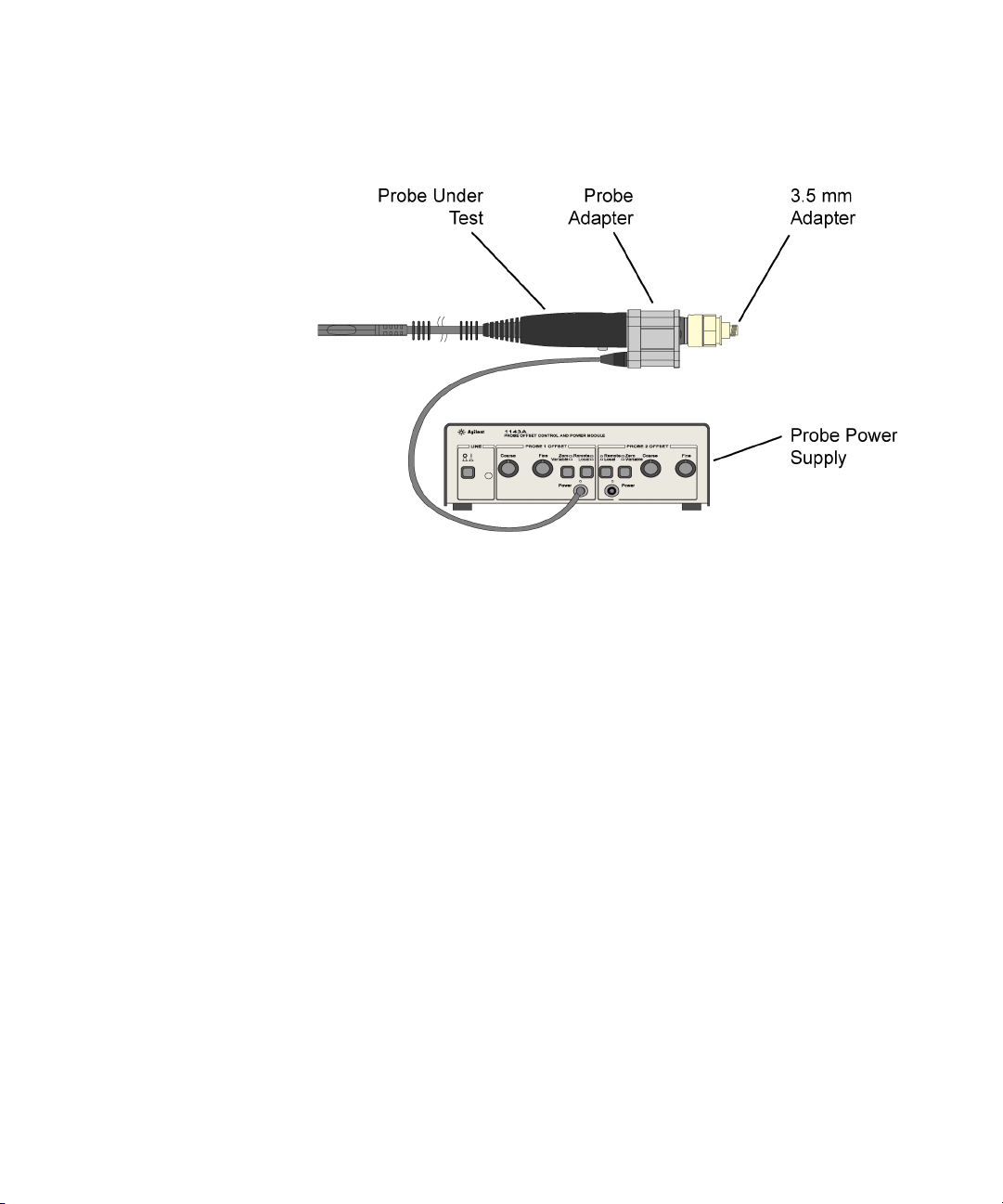
6 Connect the probe under test to the Auto Probe Adapter and
power the probe using the 1143A power supply. Install the
outside thread adapter to the Auto Probe Adapter.
38 N2795/6A User’s Guide
Page 39
Performance Verification 4
Figure 15 Probe Connected to Probe Adapter (not to scale)
Calibrating a Reference Plane
To get a reliable measurement from the VNA you must calibrate a
reference plane so that the VNA knows where the probe under test
is located along the transmission line.
7 On the VNA, press the [Cal] key.
N2795/6A User’s Guide 39
Page 40
4 Performance Verification
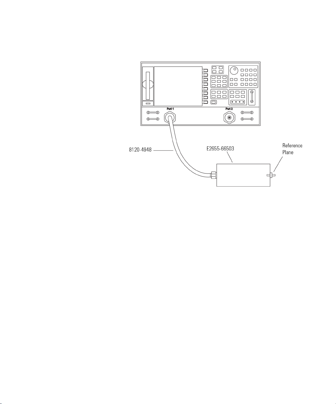
Figure 16 PV/DS Test Board Connected to VNA
8 Press the cal menu screen key.
9 Press the full 2 port screen key.
10 Connect one of the high quality SMA cables to port one and to
the pincher side of PV/DS test board.
11 The calibration reference plane is at the other end of PV/DS test
board.
40 N2795/6A User’s Guide
Page 41

Performance Verification 4
12 Perform a Calibration for the PORT 1 side of the Reference plane.
a Press the reflection screen key.
b Connect the open end of 85052D Calibration Standard
to the
non-pincher side of the PV/DS test board.
c Select the open screen key under the Forward group.
d Wait until the VNA beeps indicating that it has completed the
task.
e Connect short end of Calibration Standard to the
non-pincher side of the PV/DS test board.
f Select short screen key under the Forward group.
g Wait until the VNA beeps indicating that it has completed the
task.
h Connect load end of Calibration Standard to the non-pincher
side of the PV/DS test board.
i Select the loads screen key under the Forward group.
j Press broadband screen key selection.
k Wait until the VNA beeps indicating that it has completed the
task.
l Press the done loads screen key.
m You have just calibrated one side of the reference plane.
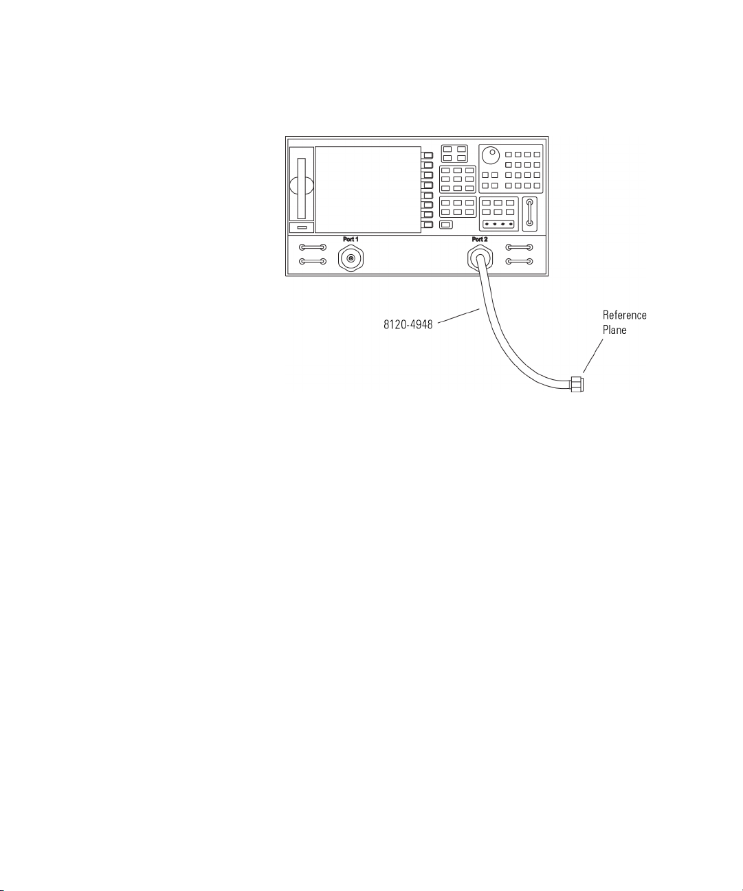
13 Connect the other high quality SMA cable to the VNA’s PORT 2.
N2795/6A User’s Guide 41
Page 42
4 Performance Verification
Figure 17 SMA Cable Connected to Port 2
14 Get the opposite sex of the Calibration Standards for the next
step.
42 N2795/6A User’s Guide
Page 43

Performance Verification 4
15 Perform Calibration for the PORT 2 side of the Reference plane.
a Press the reflection screen key.
b Connect the open end of Calibration Standard to the
available end of the PORT 2 SMA cable.
c Select the open screen key under the Reverse group.
d Wait until the VNA beeps indicating that it has completed the
task.
e Connect short end of Calibration Standard to the available
end of the PORT 2 SMA cable.
f Select short screen key the Reverse group.
g Wait until the VNA beeps indicating that it has completed the
task.
h Connect load end of Calibration Standard to the available
end of the PORT 2 SMA cable.
i Select the loads screen key the Reverse group.
j Press broadband screen key selection.
k Wait until the VNA beeps indicating that it has completed the
task.
l Press the done loads screen key.
m You have just calibrated the other side of the reference plane.
16 Press standards done key.
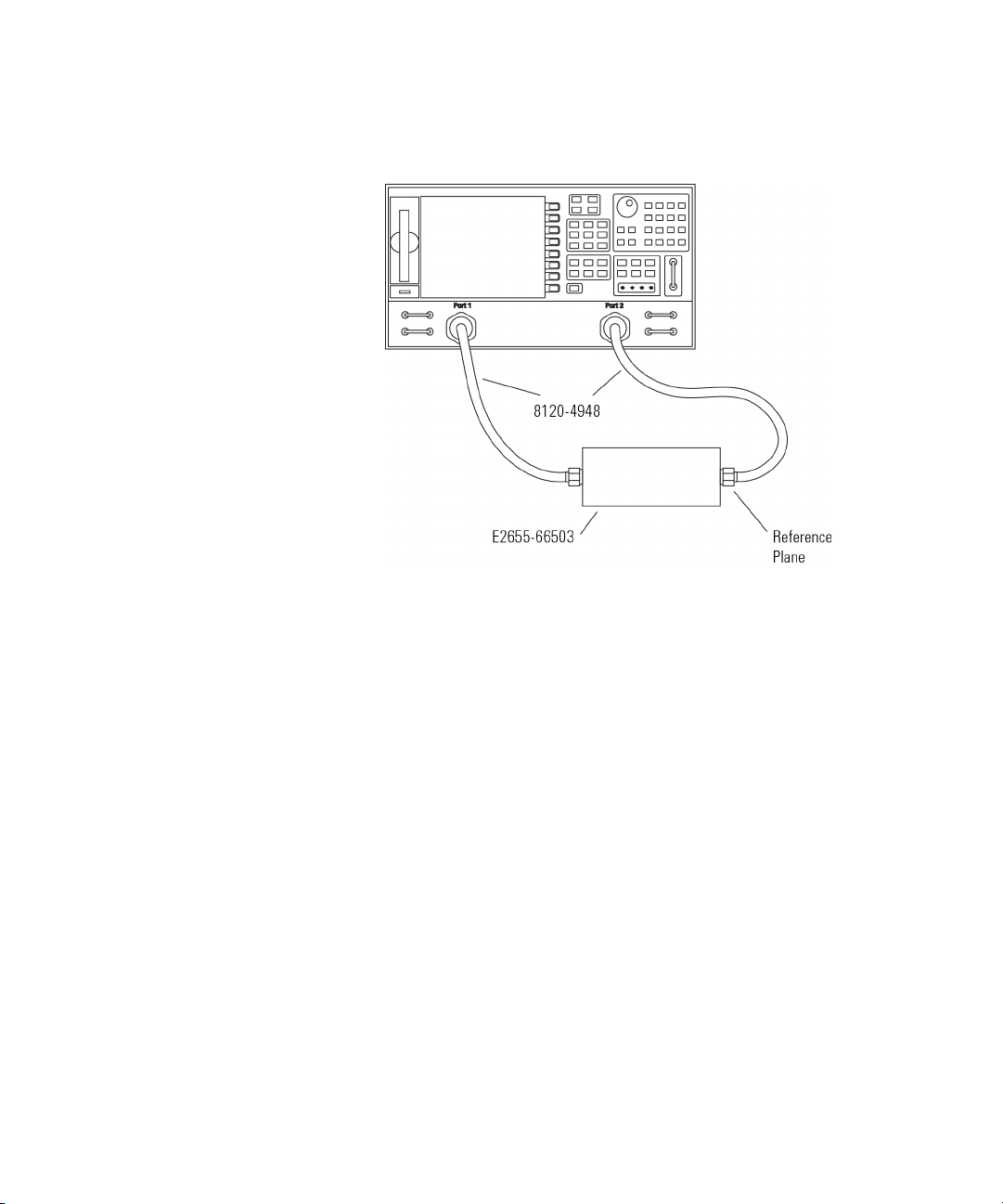
17 Connect port two SMA cable to the non-pincher side of PV/DS
test board.
N2795/6A User’s Guide 43
Page 44
4 Performance Verification
Figure 18 Forward and Reverse Setup
18 Press the transmission screen key.
19 Press the do both fwd and reverse screen key.
20 Wait until the VNA beeps four times indicating that it has
completed the task.
21 Press the isolation screen key.
22 Press the omit isolation screen key.
23 Press done 2 port cal screen key.
24 Set the VNA's averaging to off.
25 Save the reference plane cal by pressing the [save recall] key then
the [save state] key.
26 You may change name if you wish.
27 Press the [scale reference] key. Then set the scale to 1 dB per
division and the reference position for 7 divisions.
28 Set reference value for 0 dB.
29 Press the [measure] key.
30 Press the s21 screen key.
44 N2795/6A User’s Guide
Page 45

Performance Verification 4
31 Ensure s21 response on screen is flat out to 1 GHz (N2795A) or
2 GHz (N2796A).
Measuring Vin Response
32 Position the probe conveniently to allow the probe tip to be
normal to the PV/DS board.
33 Hold the probe in position, or use a positioner, so that the signal
and ground are making contact and are perpendicular to the
fixture.
34 Press the [Sweep Setup] key on the VNA. Then press the trigger
menu screen key. Select the continuous screen key.
35 You should now have the V
waveform on screen.
in
36 Select [display] key then data->memory screen key.
37 You have now saved Vin waveform into the VNA's memory for
future use.
Measuring Vout Response
38 Disconnect the PORT 2 cable from PV/DS test board and attach
to probe output on the AutoProbe Adapter.
39 Connect the Calibration Standard load to PV/DS test board
(non-pincher side).
40 Press [scale reference] key on the VNA.
41 Set reference value to –20 dB.
42 Hold probe in place as described previously.
43 The display on screen is V
out
.
Displaying Vout/Vin Response on the VNA
44 Press the [Display] key.
45 Then select the Data/Memory screen key. You may need to adjust
the Reference Value, located under the Scale Ref key, slightly to
position the waveform at center screen.
46 Press marker key and position the marker to the first point that
the signal is –3 dB below center screen.
N2795/6A User’s Guide 45
Page 46

4 Performance Verification
47 Read marker frequency measurement and record it in the test
record located later in this chapter.
48 The bandwidth test passes if the frequency measurement is
greater that the probe's bandwidth limit.
N2795A bandwidth:. . . . . . . . . . . . . . . . . . . . . . . . . . . . . . . . . . . . . . . . 1 GHz
N2796A bandwidth:. . . . . . . . . . . . . . . . . . . . . . . . . . . . . . . . . . . . . . . . 2 GHz
46 N2795/6A User’s Guide
Page 47
Performance Verification 4
Performance Test Record
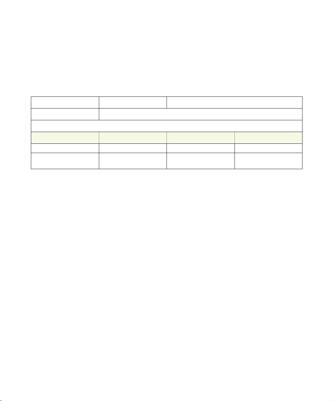
Table 9 Performance Test Record
Model #: Date: Tested by:
Serial #: Recommended next test date:
Recommended Test Interval: 1 year / 2000 hours
Probe Amplifier Test Limits Result Pass/Fail
Test 1. DC Input Resistance 1 MΩ + 0%, –2.5%
Test 2. Bandwidth ≥ 1 GHz (N2795A)
≥ 2 GHz (N2796A)
N2795/6A User’s Guide 47
Page 48

4 Performance Verification
48 N2795/6A User’s Guide
Page 49

Index
Index
A
accessories
attaching, 8
supplied, 8
accessory kit, 10
altitude, 27
attenuation ratio, 27
B
bandwidth, 12, 27
C
cable, 6
CE mark, 25
channel identification rings, 10
cleaning, 6
compatibility, 7
compatible oscilloscopes, 7
copper pads, 9, 15
D
dimensions, 29
dynamic range, 19, 27
E
environmental specifications, 27
ESD, 6
F
flex ground, 9
flex nose clip, 9, 10
flexible nose clips, 17
frequency response, 31
functional test, 20
G
ground blade, 9, 13
ground leads, 18
H
headlight, 11
humidity, 27
I
Infiniium, 7
input capacitance, 28
input impedance over frequency, 33
input resistance, 28
inspecting, 21
ISM1-A, 25
K
Keysight Technologies, contacting, 22
N
N5442A adapter, 7
O
offset ground, 9, 13
offset range, 19
operating temperature
probe, 27
oscilloscope
compatible, 7
software version, 7
oscilloscope compatibility, 7
output impedance, 28
P
performance test record, 47
performance verification, 35
probe
cleaning, 6
configurations, 12
dimensions, 29
handling, 23
inspecting, 21
service, 22
probe accessories, 12
probe, inspecting, 21
R
returning for service, 22
right angle ground, 9, 10
right-angle ground, 13, 18
rigid probe tip, 9, 10
rigid tips, 13
S
safety information, 23
service, 22
solderable tip, 18
specifications, 27
spring probe tip, 9, 10
spring tips, 13
supplied accessories, 8
T
temperature, 27
W
weight, 28
Y
Y-lead adapter, 9, 10, 16
Y-lead with clips, 17
Y-leads, 15, 16
N2795/6A User’s Guide 49
Page 50

Index
50 N2795/6A User’s Guide
 Loading...