

Page 1
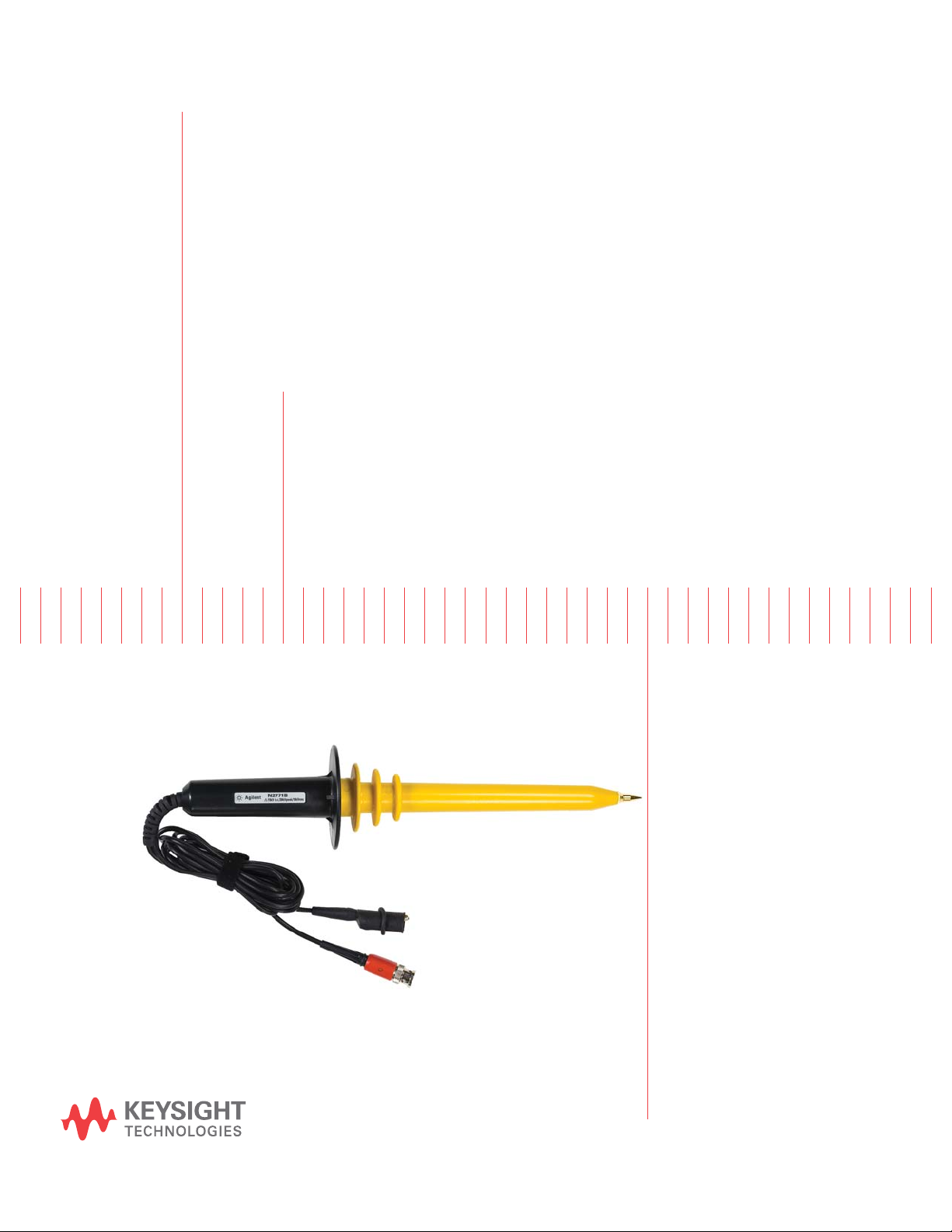
Keysight N2771B
15 kV High Voltage Probe
User’s Guide
Page 2
Notices
CAUTION
WARNING
© Keysight Technologies, Inc. 2012-2016
No part of this manual may be reproduced in
any form or by any means (including
electronic storage and retrieval or
translation into a foreign language) without
prior agreement and written consent from
Keysight Technologies, Inc. as governed by
United States and international copyright
laws.
Manual Part Number
N2771-92013
Edition
Sixth edition, 2016
Published in USA
Keysight Technologies, Inc.
1400 Fountaingrove Parkway
Santa Rosa, CA 95403 USA
Warranty
The material contained in this document
is provided “as is,” and is subject to
being changed, without notice, in future
editions. Further, to the maximum
extent permitted by applicable law,
Keysight disclaims all warranties, either
express or implied, with regard to this
manual and any information contained
herein, including but not limited to the
implied warranties of merchantability
and fitness for a particular purpose.
Keysight shall not be liable for errors or
for incidental or consequential damages
in connection with the furnishing, use,
or performance of this document or of
any information contained herein.
Should Keysight and the user have a
separate written agreement with
warranty terms covering the material in
this document that conflict with these
terms, the warranty terms in the
separate agreement shall control.
Technology Licenses
The hardware and/or software described in
this document are furnished under a license
and may be used or copied only in
accordance with the terms of such license.
U.S. Government Rights
The Software is "commercial computer
software," as defined by Federal Acquisition
Regulation ("FAR") 2.101. Pursuant to FAR
12.212 and 27.405-3 and Department of
Defense FAR Supplement ("DFARS")
227.7202, the U.S. government acquires
commercial computer software under the
same terms by which the software is
customarily provided to the public.
Accordingly, Keysight provides the Software
to U.S. government customers under its
standard commercial license, which is
embodied in its End User License Agreement
(EULA), a copy of which can be found at
www.keysight.com/find/sweula. The
license set forth in the EULA represents the
exclusive authority by which the U.S.
government may use, modify, distribute, or
disclose the Software. The EULA and the
license set forth therein, does not require or
permit, among other things, that Keysight:
(1) Furnish technical information related to
commercial computer software or
commercial computer software
documentation that is not customarily
provided to the public; or (2) Relinquish to,
or otherwise provide, the government rights
in excess of these rights customarily
provided to the public to use, modify,
reproduce, release, perform, display, or
disclose commercial computer software or
commercial computer software
documentation. No additional government
requirements beyond those set forth in the
EULA shall apply, except to the extent that
those terms, rights, or licenses are explicitly
required from all providers of commercial
computer software pursuant to the FAR and
the DFARS and are set forth specifically in
writing elsewhere in the EULA. Keysight
shall be under no obligation to update,
revise or otherwise modify the Software.
With respect to any technical data as
defined by FAR 2.101, pursuant to FAR
12.211 and 27.404.2 and DFARS 227.7102,
the U.S. government acquires no greater
than Limited Rights as defined in FAR 27.401
or DFAR 227.7103-5 (c), as applicable in any
technical data.
Safety Notices
A CAUTION notice denotes a hazard.
It calls attention to an operating
procedure, practice, or the like that,
if not correctly performed or
adhered to, could result in damage
to the product or loss of important
data. Do not proceed beyond a CAU-
TION notice until the indicated conditions are fully understood and
met.
A WARNING notice denotes a hazard. It calls attention to an operating procedure, practice, or the like
that, if not correctly performed or
adhered to, could result in personal
injury or death. Do not proceed
beyond a WARNING notice until the
indicated conditions are fully
understood and met.
WEEE Compliance
This product complies with
the WEEE Directive
2012/19/EU marking
requirements. The affixed
label indicates that you
must not discard this
electrical/electronic product
in domestic household waste.
Product Category: With reference to the
equipment types in the WEEE Directive
Annex I, this product is classed as a
"Monitoring and Control Instrumentation"
product.
Do not dispose in domestic household
waste.
To return unwanted products, contact your
local Keysight office, or see
www.keysight.com for more information.
Page 3

Introduction
Introduction
The Keysight N2771B High Voltage Divider Probe is an accessory
to be used with analog or digital oscilloscopes having input
resistance of 1 MΩ (±1%) and nominal input capacitance between
6 and 20 pF. The N2771B is a 1000:1 divider which extends the
voltage measurement capability to maximum 15 kV (DC + AC
Contents
peak), 10 kV
Safety Precautions 4
IEC Measurement Category Definitions 6
Operation 7
Frequency Compensation Adjustment 9
Cleaning 9
Characteristics 10
Contacting Keysight 12
AC, or 30 kV
rms
(< 20 ns pulse width).
peak
3
Page 4
Safety Precautions
WARNING
WARNING
WARNING
WARNING
WARNING
Safety Precautions
This high voltage probe is designed to prevent accidental shock to
the operator when properly used. This user guide must be read and
understood prior to using the probe. Improper procedures or
incorrect analysis of the measurement situation can result in serious
shock.
If the probe is subjected to voltages over 15kV (DC + AC peak) or
10 kV rms then DO NOT USE. The probe could potentially be
damaged. Return the probe immediately to a Keysight service
center for performance validation.
This high voltage probe is designed for use within Measurement
Category I (CAT I) only. Do not use the probe for measurements
performed on circuits defined by any other measurement category or
transient overvoltages of more than 1500V. Refer to “IEC
Measurement Category Definitions" on page 6 for a definition of
measurement categories.
Do not exceed 60 seconds of contact between the probe and
circuit-under-test when measuring voltages ≥ 8 kV (DC) or ≥ 5kV
(AC, rms). Keysight recommends that an interval of 5 minutes be
taken between measurements.
This high voltage probe must only be used by personnel who are
trained, experienced, or otherwise qualified to recognize hazardous
situations and who are trained in the safety precautions that are
necessary to avoid possible injury when using such a device.
Do not work alone when working with high voltage circuits.
4
Page 5
Safety Precautions
WARNING
WARNING
WARNING
WARNING
WARNING
WARNING
For your own safety, inspect the probes for cracks and frayed or
broken leads before each use. If defects are noted, DO NOT use the
probe.
Hands, shoes, floor and work bench must be dry. Avoid making
measurements under humid, damp or other environmental
conditions that might effect the safety of the measurement situation.
It is advisable to turn the high voltage source off before connecting
or disconnecting the probe.
The probe body should be kept clean and free of any conductive
contamination. Refer to the section on cleaning.
The ground lead is critical to the safe operation of the probe. Failure
to make this connection when making high voltage measurements
may result in personal injury or damage to the probe or oscilloscope.
This connection must always be made BEFORE the probe tip comes
in contact with the high voltage and must not be removed until the
probe tip has been removed from the high voltage source.
Do not attempt to take measurements from sources where the
chassis or return lead is not grounded.
5
Page 6

IEC Measurement Category Definitions
IEC Measurement Category Definitions
Definitions and Examples (Clause 6.5.2).
Measurement Category I (CAT I)
Measurement category I is for measurements performed on circuits
not directly connected to a mains supply.
Example Measurements in circuits not derived from a mains
supply and specially protected (internal) circuits derived from a
mains supply. In the latter case, transient stresses are variable. For
that reason, it is required that the transient withstand capability of
the equipment is made known to the user.
Measurement Category II (CAT II)
Measurement category II is for measurements performed on
circuits directly connected to the low voltage installation.
Example Household appliances, portable tools, and similar
equipment.
Measurement Category III (CAT III)
Measurement category III is for measurements performed in the
building installation.
Example Measurements on distribution boards, circuit breakers,
wiring including cables, bus-bars, junction boxes, switches,
socket-outlets in the fixed installation and equipment for industrial
use like, for example, stationary motors with permanent
connections to the fixed installation.
Measurement Category IV (CAT IV)
Measurement category IV is for measurements performed at the
source of the low-voltage installation.
Example Electricity meters and measurements on primary
over-current protection devices and ripple control units.
6
Page 7
Operation
WARNING
WARNING
WARNING
WARNING
Operation
1 Connect the probe to the BNC input of the oscilloscope.
2 Select the desired volts/division range. (If you can set probe
attenuation on the oscilloscope, set it to 1000:1)
3 Whenever possible, turn the high voltage source off before
making any connections.
4 Connect the divider probe ground lead (alligator clip) to a good
earth ground or reliable chassis ground.
5 Connect the probe to the voltage source.
6 Before turning on the high voltage source, make sure that no
part of the person holding the probe is touching the device
under test. Once this is certain, turn on the high voltage source.
7 Measure the voltage under test and observe the waveform on
the oscilloscope. Remember the actual voltage is 1000 times
greater than the oscilloscope waveform if the probe attenuation
on the oscilloscope has been set to 1:1.
8 Turn off the high voltage source.
9 Disconnect the Keysight N2771B High Voltage Probe from the
high voltage source BEFORE disconnecting the ground clip
lead.
Do not attempt to take measurements from sources where the
chassis or return lead is not grounded.
The ground lead is critical to the safe operation of the probe. Failure
to make this connection when making high voltage measurements
may result in personal injury or damage to the probe or oscilloscope.
This connection must always be made BEFORE the probe tip comes
in contact with the high voltage and must not be removed until the
probe tip has been removed from the high voltage source.
Do not connect the ground clip lead to the high voltage source for
any reason.
Do not make any floating measurements with the Keysight N2771B
High Voltage probe.
7
Page 8

Operation
WARNING
WARNING
Do not exceed 60 seconds of contact between the probe and
circuit-under-test when measuring voltages
≥ 8 kV (DC) or ≥ 5kV
(AC, rms). Keysight recommends that an interval of 5 minutes be
taken between measurements.
This high voltage probe is designed for use within Measurement
Category I (CAT I) only. Do not use the probe for measurements
within the other measurement categories or transient overvoltages
of more than 1500V.
8
Page 9
Frequency Compensation Adjustment
WARNING
CAUTION
Frequency Compensation Adjustment
The N2771B High Voltage Probe has a Frequency Compensation
adjustment that compensates for the input capacitance of the
oscilloscope being used with the probe. Use a square-wave
generator set for approximately 100 Hz output. Proceed with the
following steps for frequency compensation.
1 Connect the probe to the oscilloscope.
2 Connect probe tip to square-wave generator.
3 Adjust the square wave generator for approximately 10 volts
amplitude.
4 Adjust the oscilloscope time base for 20 μs/div.
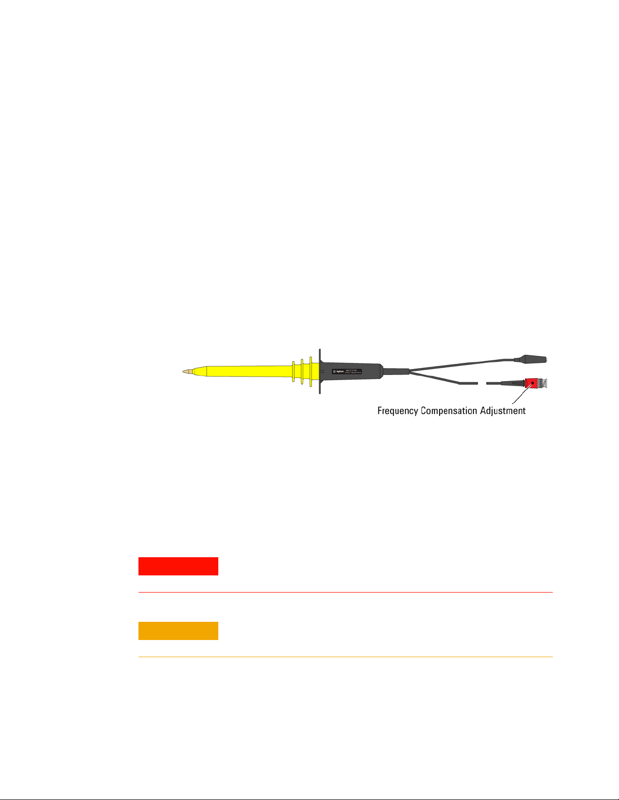
5 Use a trimmer tool to adjust the compensation capacitor for the
flattest pulse top. See the figure below for the location of the
adjustment.
Cleaning
Figure 1 Location of Frequency Compensation Adjustment
Clean only the exterior probe body and cables. Use a soft cotton
cloth lightly moistened with a mild solution of detergent and water.
Do not allow any portion of the probe to be submerged at any time.
Dry the probe thoroughly before attempting to make voltage
measurements.
Do not subject the probe to solvents or solvent fumes as these can cause
deterioration of the probe body and cables.
9
Page 10
Characteristics
Characteristics
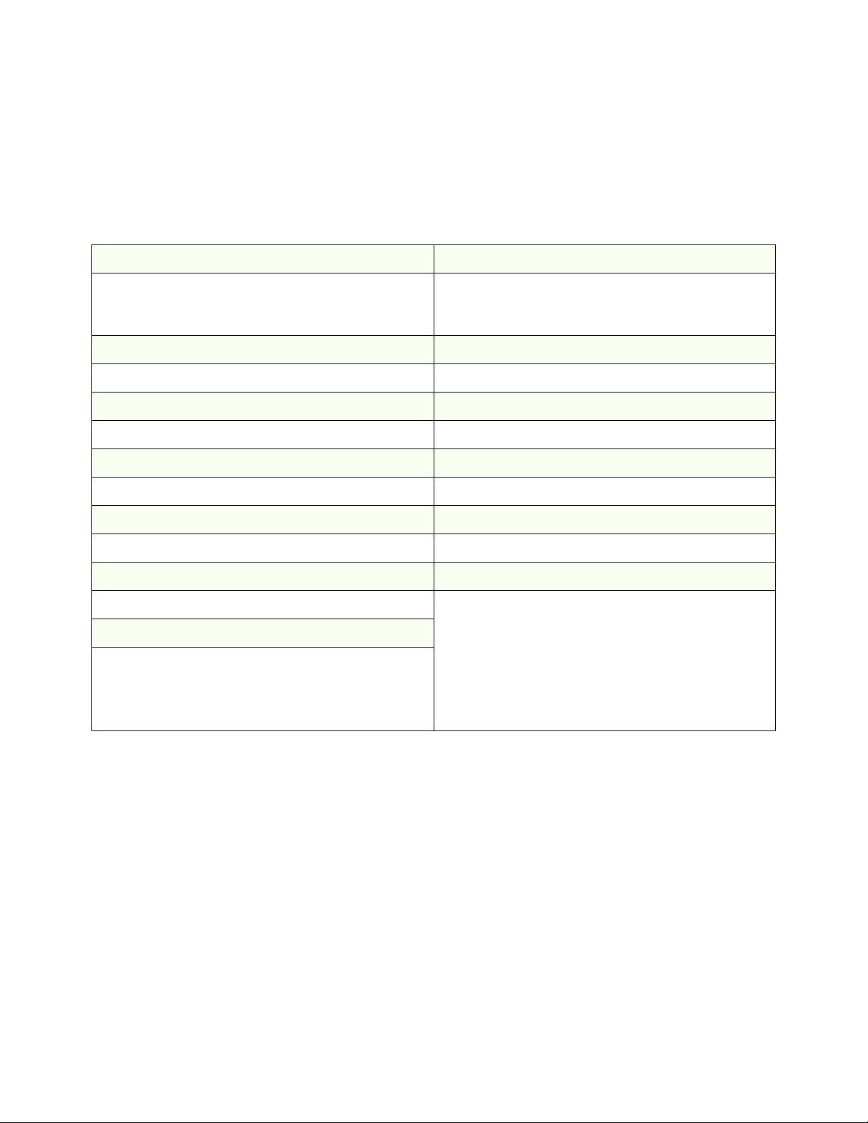
Table 1 Characteristics (Not Warranted)
Maximum Input Voltage (CAT I) Temperature Coefficient
DC Voltage: 15 kV
AC Voltage: 10 kV
Peak Voltage: 30 kV
Compensation Range Division Ratio
For input capacitance of 6 pF to 20 pF 1000:1
Bandwidth Designed For Use In
50 MHz (–3 dB) POLLUTION DEGREE 2
Input Resistance Operating Temperature
100 MΩ, when terminated by 1 MΩ0 °C to +50 °C
Cable Length: Storage Temperature:
2 meter −20 °C to +70 °C
Altitude: Humidity
Up to 2,000 meters (6,561 ft) Up to 80% relative humidity at +40 °C
Accuracy:
DC Volts: ±2, 5% (below 10 kV)
DC Volts: ±4% (between 10 kV and 15 kV)
AC Volts: ±5% at 1 kHz
AC Volts: ±3 dB between 1 kHz and 50 MHz
rms
(< 20 ns pulse width)
peak
Less than 200 ppm/ °C
10
Page 11
Voltage Derating
Voltage Derating
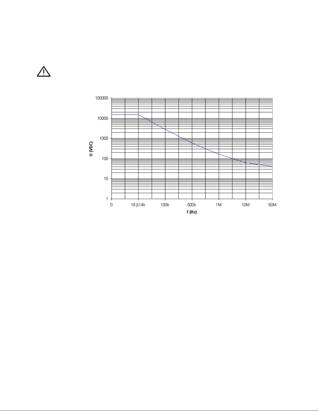
The following graph shows the voltage versus frequency derating
curve for the Keysight N2771B High Voltage Probe.
Figure 2 Voltage Versus Frequency Derating Curve
11
Page 12

Contacting Keysight
Contacting Keysight
Information on contacting Keysight Technologies can be found at:
www.keysight.com/find/contactus
12
 Loading...